


CARVIN ENGINEERING DATA |
XC3000 STEREO 2/3-WAY ELECTRONIC CROSSOVER |
OPERATING MANUAL |
|
|
|
|
|
CHANNEL ONE |
|
|
|
|
|
|
|
|
|
|
CHANNEL TWO |
|
|
|
|
|
|
|
|
|
||
|
|
|
|
|
|
|
|
FREQUENCY |
|
|
|
|
|
|
|
|
|
FREQUENCY |
|
|
|
|
ON |
||||
XC3000 |
0dB |
|
0dB |
0dB |
0dB |
200 |
300 |
450 |
|
2. |
3.0 |
|
.0 |
0dB |
0dB |
0dB |
0dB |
200 |
300 |
450 |
|
|
2. |
3.0 |
.0 |
|
|
|
OFF |
|
|
|
90 |
|
600 |
x1 |
0.8 |
|
|
7.0 |
|
OFF |
|
|
90 |
|
600 |
x1 |
0.8 |
|
7.0 |
|
|
||
|
40Hz |
|
|
|
|
x10 |
|
|
|
40Hz |
|
|
|
x10 |
|
|
PWR |
||||||||||
24dB/OCTAVE |
+6 |
|
+6 |
+6 |
+6 |
50 |
|
1k |
|
0.6 |
|
10 |
+6 |
+6 |
+6 |
+6 |
50 |
|
1k |
|
|
0.6 |
|
10 |
|
||
|
|
Hz |
|
kHz |
Hz |
|
|
kHz |
|
|
|||||||||||||||||
PEAK |
|
|
|
|
|
|
|
|
|
|
|
|
|
PEAK |
|
|
|
|
|
|
|
|
|
|
|
|
|
GAIN |
SUB SONIC LOW LEVEL |
MID LEVEL |
HIGH LEVEL |
LOW / MID |
|
MID / HIGH |
3 WAY |
GAIN |
SUB SONIC LOW LEVEL |
MID LEVEL |
HIGH LEVEL |
LOW / MID |
|
|
MID / HIGH |
3 WAY |
OFF |
||||||||||
|
|
|
|
||||||||||||||||||||||||
Stereo 2/3Way Crossover |
LOW LEVEL |
|
HIGH LEVEL |
LOW/HIGH |
|
|
|
|
2 WAY |
|
LOW LEVEL |
|
HIGH LEVEL |
LOW/HIGH |
|
|
|
|
|
2 WAY |
|
||||||
Congratulations on your purchase of the CARVIN XC3000 Stereo 2 / 3 - way Electronic Crossover. The XC3000 was designed with the professional in mind. Your unit has been engineered and assembled in the U.S.A., using only high quality electronic components and uncompromising workmanship. The XC3000 provides the best available crossover networks consisting of a forth-order statevariable implementation of Linkwitz-Riley crossover alignments. This provides a 24 dB/octave slope while maintaining optimal phase integrity. The XC3000 contains a host of valuable features found in only the best of professional audio equipment. These include a switchable 40Hz Sub Sonic filter, a 10x frequency multiplier, switchable Tri-Amp and Bi-Amp modes, balanced input and output connectors, and phase inversion switches. The XC3000 is designed for maximum signal quality and control, and should give you years of trouble free service.
BI-AMP & TRI-AMP THEORY
Bi-Amplification and Tri-Amplification involve higher protection to sound systems as well as increased performance. Bi-Amping involves dividing a full range signals into two distinct low pass and high pass (low frequency and high frequency) signals and then amplifying these signals with separate amplifiers for later connection to their proper woofer and horn speakers.
Tri-Amplification involves the same principle as Bi-Amping except that separate high-pass, mid band, and low pass signals are fed to (3) separate amplifiers for subsequent connection to woofer, midrange, and high frequency speakers.
These frequency divisions are done actively with an efficient 24dB/octave roll off prior to the power amplifiers. This allows the amplifiers to power a defined frequency range (low, mid or high) instead of a full range frequency signal. Due to increased efficiency of the amplifier (amplifying a distinct frequency range), a cleaner, and more powerful output is afforded. Bi/Tri-Amplifying is especially useful in selecting any number of various crossover points and adjusting individual frequency level gain., thus enabling you to better control the overall response of your sound system. Bi/Tri-Amplification is useful as a means of offering greater protection, more power with less distortion and better overall control of your sound system.
RECEIVING INSPECTION
INSPECT YOUR XC3000 FOR ANY DAMAGE which may have occurred during shipping. If any damage is found, notify the shipping company and call CARVIN immediately.
SAVE THE CARTON & ALL PACKING MATERIALS. In the event you have to reship your mixer, always use the original carton and packing material. This will provide the best possible protection for your unit during shipment. CARVIN and the shipping company are not liable for any damage caused by improper packing.
SAVE YOUR INVOICE. It will be required for warranty servicing of your unit. Always check your invoice against the items you have received.
SHIPMENT SHORTAGE. If you find items missing, it may be that they were shipped separately. Please allow several days for the rest of your order to arrive before inquiring. If you determine (after allowing an appropriate amount of time) you have not received all the items you ordered, please call CARVIN
TROUBEL SHOOTING
SAVE YOUR INVOICE. It will be required for warranty servicing of your unit. Always check your invoice against the items you have received.
SHIPMENT SHORTAGE. If you find items missing, it may be that they were shipped separately. Please allow several days for the rest of your order to arrive before inquiring. If you determine (after allowing an appropriate amount of time) you have not received all the items you ordered, please call CARVIN
SAVE YOUR INVOICE. It will be required for warranty servicing of your unit.
Always check your invoice against the items you have received.
SHIPMENT SHORTAGE. If you find items missing, it may be that they were shipped separately. Please allow several days for the rest of your order to arrive before inquiring. If you determine (after allowing an appropriate amount of time) you have not received all the items you ordered, please call CARVIN
If you determine (after allowing an appropriate amount of time) you have not received all the items you ordered, please call CARVIN
XC3000 SPECIFICATIONS:
FREQUENCY RESPONSE: |
20 Hz to 20k Hz ± 1 dB |
|
THD: |
Less than .01% 20 to 20k Hz |
|
OUTPUT (BALANCED): |
+26 dBm |
|
DYNAMIC RANGE: |
112 dB |
|
CHANNELS: |
Two Stereo 2 or 3 Way |
|
INPUT GAIN CONTROL: |
One per channel |
|
MAX. GAIN ABOVE INPUT SOURCE: |
12dB |
|
PEAK LED DETECTOR: |
Input detection at +16 dBm |
|
SUB SONIC FILTER: |
18 dB / Octave -3dB at 40Hz |
|
CROSSOVER FILTER DESIGN.: |
24 dB / Octave Linkwitz Riley |
|
LOW / MID CROSSOVER FREQ.: |
One 50 to 10 Hz sweep per channel |
|
MID / HIGH CROSSOVER FREQ.: |
One 600 to 10 k Hz sweep per channel |
|
FREQ. MULTIPLIER: |
One x1 / x10 push button switch per channel |
|
MULTIPLIER RANGE: |
x1 (95 to 1.6k Hz) and x10 (950 to 16k Hz) |
|
INPUT IMPEDANCE: |
22k Ω |
|
INPUT CONNECTORS: |
Balanced XLR and balanced (stereo) |
|
|
1 / 4” phone jacks |
|
OUTPUT CONTROL: |
Three per channel (Low, Mid, HIgh Freq.) |
|
OUTPUT IMPEDANCE: |
Less than 150 Ω |
|
OUTPUT CONNECTORS: |
Balanced XLR |
|
PHASE INVERSION: |
3 Phase inverting switches per channel |
|
MODE SWITCH: |
Bi-Amp or Tri-Amp position per channel |
|
POWER REQUIREMENTS: |
90 / 250 VAC 50-60 Hz auto switching |
|
FUSE: |
3 Amp 250v fast blow |
|
DIMENSIONS: |
19”W x 5” D x 1.7”H |
|
SHIPPING WT: |
8 lbs |
|
For you records, record the following information.
Serial No._________________ Invoice Date________________
12340 World Trade Drive San Diego, CA 92128 858.487.1600 800. 854.2235
carvin.com
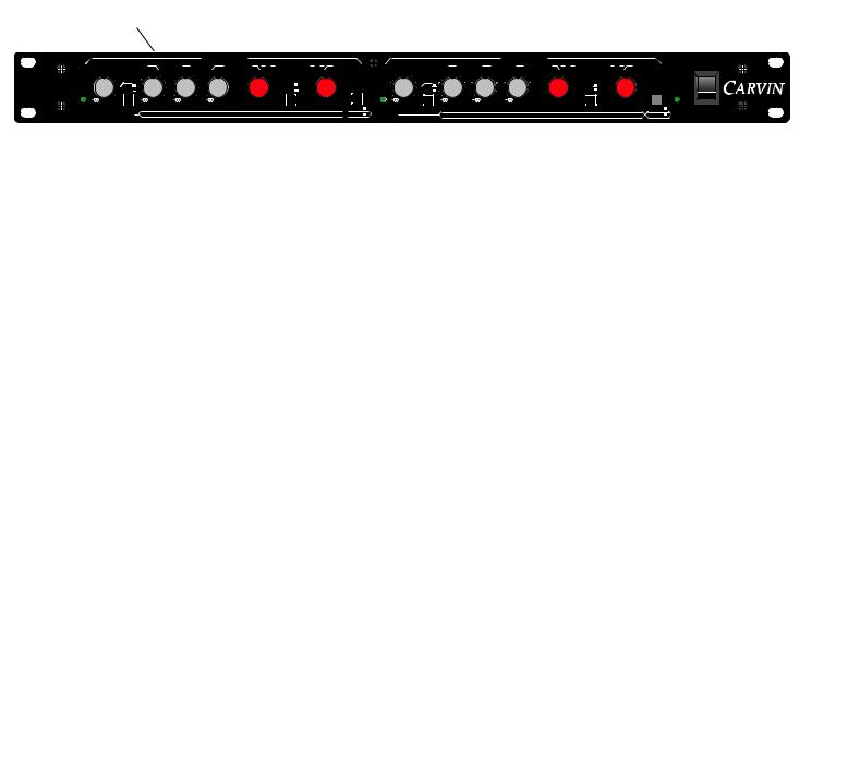
FRONT PANEL FEATURES
1 |
2 |
3 |
4 |
5 |
6 |
7 |
9 |
10 |
|
11 |
12 |
|
|
8 |
|
|
|
||||||
|
|
|
|
|
|
CHANNEL ONE |
|
CHANNEL TWO |
|
|
|
|
|
|
|
|
|
|
FREQUENCY |
FREQUENCY |
|
ON |
|
XC3000 |
0dB |
|
0dB |
0dB |
0dB |
|
300 |
450 |
|
|
3.0 |
.0 |
|
0dB |
0dB |
0dB |
0dB |
200 |
300 |
450 |
|
2 |
|
|
|
OFF |
|
|
90 |
|
|
600 |
x1 |
0.8 |
|
7.0 |
|
|
OFF |
|
|
90 |
|
600 |
x1 |
0.8 |
.0 |
|
|
|
40Hz |
|
|
|
|
x10 |
|
|
|
40Hz |
|
|
|
x10 |
PWR |
|||||||||
24dB/OCTAVE |
+6 |
|
+6 |
+6 |
+6 |
50 |
|
1k |
|
0.6 |
|
10 |
|
+6 |
+6 |
+6 |
+6 |
50 |
|
1k |
|
|
|
|
|
|
Hz |
|
kHz |
|
Hz |
|
|
|
|
||||||||||||||
PEAK |
|
|
|
|
|
|
|
|
|
|
|
|
|
PEAK |
|
|
|
|
|
|
|
|
|
|
GAIN |
SUB SONIC LOW LEVEL |
MID LEVEL |
HIGH LEVEL |
LOW / MID |
|
MID / HIGH |
3 WAY |
GAIN |
SUB SONIC LOW LEVEL |
MID LEVEL |
HIGH LEVEL |
LOW / MID |
|
|
3 WAY |
OFF |
||||||||
|
|
|
|
|||||||||||||||||||||
Stereo 2/3Way Crossover |
LOW LEVEL |
|
HIGH LEVEL |
LOW/HIGH |
|
|
|
|
2 WAY |
|
LOW LEVEL |
|
HIGH LEVEL |
LOW/HIGH |
|
|
2 WAY |
|
||||||
1. |
PEAK INDICATOR |
7. LOW / MID FREQUENCY SELECTOR |
|
|
The peak indication LED light is used to monitor both input and output distortion. THis indicator will flash whenever any of these |
This control sets the desired upper frequency crossover |
the LOW OUT and lower frequency crossover point for the MID |
||
two conditions or a combination of these condition exist. Should the peak indicator ever flash, you can compensate this condition by |
OUT. The frequency indicated by the knob pointer of this |
the LOW/MID crossover point for the channel. |
||
adjusting the gain control down (lower) accordingly. |
8. 1X / 10X BUTTON |
|
||
2. |
GAIN |
|
||
This button multiplies the selected frequency for the LOW |
network, by 1X or 10X as needed to establish a full |
|||
This control establishes the amount of input gain for the crossover. This control will also affect the output drive of the crossover |
range frequency spectrum from 50Hz to 10kHz. With the |
in the “out” position the crossover will sweep from 50Hz to |
||
thereby adjusting the overall gain of the crossover as well. Note: This control is best used in conjunction with the “peak” level |
1kHz. With the 10X button pushed “in” the crossover has |
from 500Hz to 10kHz. |
||
indicator as a means of monitoring the amount of input gain and output distortion as it relates to any overload conditions. |
9. MID / HIGH FREQUENCY SELECTOR |
|
||
3. |
SUB SONIC FILTER |
|
||
This control sets the desired upper frequency crossover |
the MID OUT and lower frequency crossover point for the HIGH |
|||
This button provides a third-order high pass filter set at 40Hz. This allows you to reduce sub sonic noise, allowing your power |
OUT. The frequency indicated by the knob pointer of this |
the MID / HIGH crossover point for the channel. |
||
amps and speakers to operate safely and more efficiently. |
10. 2 WAY / 3 WAY BUTTON |
|
||
4. |
LOW LEVEL |
|
||
This switch sets the XC3000 into either Bi-Amp or Tri- |
. In the out position the unit is set for Tri-Amp mode. When the |
|||
The LOW LEVEL control sets the output level for the channels LOW OUT jack. Which frequencies will be cut or boosted at this con- |
button is depressed the unit will operate in Bi-Amp mode, |
MID LEVEL control and output jack is not used. |
||
trol is dictated by the position of the LOW/MID frequency selector. For example, if the LOW/MID frequency control is set at |
11. |
POWER INDICATOR |
|
|
300Hz, the frequencies at and below 300Hz will be volumetrically boosted or cut by adjustment of the LOW LEVEL control. |
|
|||
5. |
MID LEVEL |
This LED illuminates when power is applied to the unit. |
|
|
12. |
POWER SWITCH |
|
||
The MID LEVEL control sets the output level for the channels MID OUT jack. Which frequencies will be cut or boosted at this con- |
|
|||
trol is determined by the positions of the LOW/MID and MID/HIGH frequency selectors. |
Push this switch vertically to the “on” position to apply |
the unit. The power indicator LED will light to show that the |
||
6. |
HIGH LEVEL |
XC3000 is on. |
|
|
CHANNEL TWO |
|
|||
The HIGH LEVEL control sets the output level for the channels HIGH OUT jack. Which frequencies will be cut or boosted at this con- |
|
|||
trol is determined by the position of the MID/HIGH frequency selector. |
The controls of Channel “TWO” are identical to the controls |
“ONE”. |
||
REAR PANEL FEATURES
5
|
|
2 |
|
|
|
|
1 |
|
|
|
|
|
|
|
|
|
|
|
||
|
|
|
|
|
|
|
|
|
|
|
|
|
|
1-800-854-2235 www.carvin.com
INTERNAL FUSE
90-250 VAC
10 VA  50-60Hz
XC3000
Electronic Crossover
SERIAL |
INPUT |
MADE IN THE |
GND |
CHANNEL ONE |
|
USA |
|||
LIFT |
|
HIGH |
PHASE |
MID |
PHASE |
|
[ LOW 1+2 ] |
|
INPUT |
LOW |
CHANNEL TWO |
PHASE |
|
HIGH |
PHASE |
MID |
PHASE |
SWITCHABLE
TO MONO
[ LOW 1+2 ]
LOW |
PHASE |
1. LINE CORD
All Carvin equipment is supplied with 3 conductor line cords for maximum safety, greatly reducing the chance of electrical shock. If the XC3000 unit is to be plugged into a (2) prong outlet, use a quality 3 to 2 prong grounded adapter. Do not defeat the grounding pin of your AC line cord as this is for your protection.
2. GROUND LIFT SWITCH
Useful in getting rid of ground loop buzzing. This switch lifts the grounds on the nputs and outputs.
3. BALANCED XLR INPUT
Offers the best connection to the XC3000. The XLR connector wiring is as follows: Pin #1 ground, Pin #2 Positive Balance, Pin #3 Negative Balance.
4. BALANCED 1 / 4” PHONE INPUT
The balanced 1 / 4” phone input jack will accept either balanced or non-balanced connections. For best results use balanced (Tip, Ring, Sleeve) connections to reduce cable hum.
5. PHASE INVERTER SWITCH
The PHASE inverter switch gives you the option of inverting the phase
of each of the main output to correct any phase inversion problem at your speakers or power amps.
6. LOW OUT XLR
The LOW OUT 1 / 4” phone jack provides a balanced output for the low pass filter of the channel. This is where you connect the power amp that will be driving your bass cabinets.
7. MID OUT XLR
The MID OUT 1 / 4” phone jack provides a balanced output for the band pass filter of the channel. This is where you connect the power amp that will be driving your mid range cabinets.
8. HIGH OUT XLR
The HIGH OUT 1 / 4” phone jack provides a balanced output for the high pass filter of the channel. This is where you connect the power amp that will be driving your high frequency horns or tweeters.
9. MONO (LOW 1+2) SWITCH
Combines both signals from each channel’s low pass filters. Either or both LOW outputs may be used. This is where you would connect a power amp to drive a mono subwoofer sustem.
 Loading...