


CARVIN ENGINEERING DATA CG200 Optical Compressor/Gate INSTRUCTIONS
Congratulations on your purchase of the CARVIN CG200 two channel Optical Compressor/Gate. The CG200 was designed with the professional in mind. Your unit has been engineered and assembled in the U.S.A., using only high quality electronic components and uncompromising workmanship. The CG200 was designed around hand matched analog optoisolators. Unlike many compressor/gates which use higher noise VCA’s, the CG200 is based on classic optical compressors from the 60’s that had that warmth and softness that cannot be recreated with VCA’s. Optoisolators are also known for their extremely low distortion.
RECEIVING INSPECTION
INSPECT YOUR ITEM FOR ANY DAMAGE which may have occurred during shipping. If any damage is found, please notify the shipping company & CARVIN.
SAVE THE CARTON & ALL PACKING MATERIALS. In the event you have to re-ship your unit, always use the original carton and packing material. This will provide the best possible protection during shipment. CARVIN and the shipping company are not liable for any damage caused by improper packing.
SAVE YOUR INVOICE. It will be required for warranty service if needed in the future. SHIPMENT SHORTAGE. If you find items missing, they may have been shipped separately. Please allow several days for the rest of your order to arrive before
inquiring.
RECORD THE SERIAL NUMBER on the enclosed warranty card or below on this manual for your records. Keep your portion of the card and return the portion with your name and comments to us.
For your records, you may wish to record the following information.
Serial No._____________________ Invoice Date_______________
CG200 SPECIFICATIONS
FREQUENCY RESPONSE: |
20Hz TO 20kHz +/- 1dB |
DYNAMIC RANGE: |
115dB |
MAX INPUT LEVEL: |
+20dBu |
THD+N: |
LESS THAN 0.002% 20Hz TO 20kHz, |
|
NO COMPRESSION/GATING, 0dB INPUT |
|
LESS THAN 0.05%, ANY AMOUNT OF |
|
COMPRESSION, 0dB INPUT |
|
ATTACK AND RELEASE TIMES NOMINAL |
INPUT IMPEDANCE: |
20K BALANCED XLR |
CROSSTALK: |
<-90dB 20Hz TO 20kHz |
OUTPUT GAIN: |
-∞ TO +12dB |
COMPRESSOR |
|
THRESHOLD RANGE: |
-30bB to +20dB |
RATIO: |
2:1 TO 20:1 |
ATTACK TIME: |
4mS TO 400mS |
RELEASE TIME: |
10mS TO 2 SEC |
GATE |
|
THRESHOLD RANGE: |
OFF(OPEN GATE) TO +10dB |
RATIO: |
1:1(OFF) TO 30:1 |
RELEASE TIME: |
1mS TO 2 SEC |
INPUTS AND OUTPUTS: |
XLR BALANCED AND 1/4” UNBALANCED |
SIDECHAIN INPUT: |
1/4” UNBALANCED |
INPUT LEVEL SELECTION: |
0dBu or +6dBu |
POWER REQUIREMENTS: |
4VA 90-250VAC, 50/60Hz SWITCHING SUPPLY |
FUSE: |
INTERNAL 1.5A FAST BLOW |
DIMENSIONS: |
1 3/4”H x 19”W x 6”D |
SHIPPING WEIGHT: |
7 LBS |
CONNECTING UP
The CG200 can be used in various applications that require different configuration within a sound system. Fig. 1 shows the CG200 connected between the stereo output of a mixer and the inputs of a power amp. This is best for compressing or gating an entire main mix of program material. Fig. 2 depicts a channel insert connection. This is done with a TRS (tip send, ring return) Y-cable. The signal is sent out of the channel, compressed/gated and returned into the channel. This is a typical set-up on most vocal or drum microphone channels. Fig. 3 depicts a mic channel direct out to the SIDE CHAIN INPUT. The mic signal triggers the
compressor/gate .
POWER AMP
DCM1000
∞ |
∞ |
∞ |
∞ |
FIG. 1
|
|
CG200 |
INPUTS |
1-800-854-2235 |
OPTICAL COMPRESSOR/GATE |
UNBAL |
|
www.carvin.com |
|
|
|
INTERNAL FUSE |
SERIAL NUMBER |
|
|
|
GND |
|
|
90-250 VAC |
USA |
|
|
10 VA 50-60Hz |
LIFT |
|
|
L-R OUTPUT
 0 dBu
0 dBu  +6 dBu
CH1 |
|
|
SIDE CHAIN |
OUTPUTS |
INPUTS |
|
|
|
INPUT |
UNBAL |
UNBAL |
|
|
STEREO |
|
|
LINK |
UNBAL |
|
|
Enable the STEREO LINK switch so both channels are controlled by the settings on Channel 1.
CH2
OUTPUTS
SIDE CHAIN
INPUT  UNBAL
UNBAL
 0 dBu
0 dBu 
 +6 dBu
FIG. 2
|
|
CG200 |
|
CH1 |
|
|
CH2 |
|
|
|
INPUTS |
|
OUTPUTS |
INPUTS |
|
OUTPUTS |
|
1-800-854-2235 |
OPTICAL COMPRESSOR/GATE |
|
SIDE CHAIN |
|
|
SIDE CHAIN |
|
|
www.carvin.com |
|
|
UNBAL |
INPUT |
UNBAL |
UNBAL |
INPUT |
UNBAL |
INTERNAL FUSE |
SERIAL NUMBER |
|
|
|
STEREO |
|
|
|
|
GND |
0 dBu |
|
|
LINK |
0 dBu |
|
|
90-250 VAC |
USA |
UNBAL |
|
|
|
|||
10 VA 50-60Hz |
LIFT |
+6 dBu |
|
|
|
+6 dBu |
|
|
L-R OUTPUT
POWER AMP
DCM1000
∞ |
∞ |
FIG. 3
|
|
CG200 |
INPUTS |
1-800-854-2235 |
OPTICAL COMPRESSOR/GATE |
UNBAL |
|
www.carvin.com |
|
|
|
INTERNAL FUSE |
SERIAL NUMBER |
|
|
|
GND |
|
|
90-250 VAC |
USA |
|
|
10 VA 50-60Hz |
LIFT |
|
|
Connect the CG200 between the CD player and the mixer. Use a standard unbalanced 1/4” cable and “half insert” into the INSERT jack on the mixer and connect the other end to the SIDE CHAIN INPUT on the CG200. Connect a vocal mic to the same channel as the insert cable on the mixer. The CG200 will compress the CD audio whenever someone speaks into the mic.
CH1 |
|
|
CH2 |
|
|
OUTPUTS |
INPUTS |
SIDE CHAIN |
OUTPUTS |
SIDE CHAIN |
|
|
||
INPUT |
UNBAL |
UNBAL |
INPUT |
UNBAL |
|
STEREO |
|
|
|
|
LINK |
|
|
|
0 dBu |
UNBAL |
|
0 dBu |
|
+6 dBu |
|
+6 dBu |
|
|
|
|
|
Enable |
the STEREO |
|
|
|
LINK switch so both |
|
|
CD Player |
|
channels are controlled |
|
|
|
by the |
settings on |
|
Channel 1.
c
76-00120 0403 |
12340 World Trade Drive, San Diego, CA 92128 |
|
(800) 854-2235 www.carvin.com |
||
|
|
|
2 |
|
|
|
6 |
|
|
|
|
|
|
|
10 |
11 |
12 |
13 |
14 |
15 |
7 |
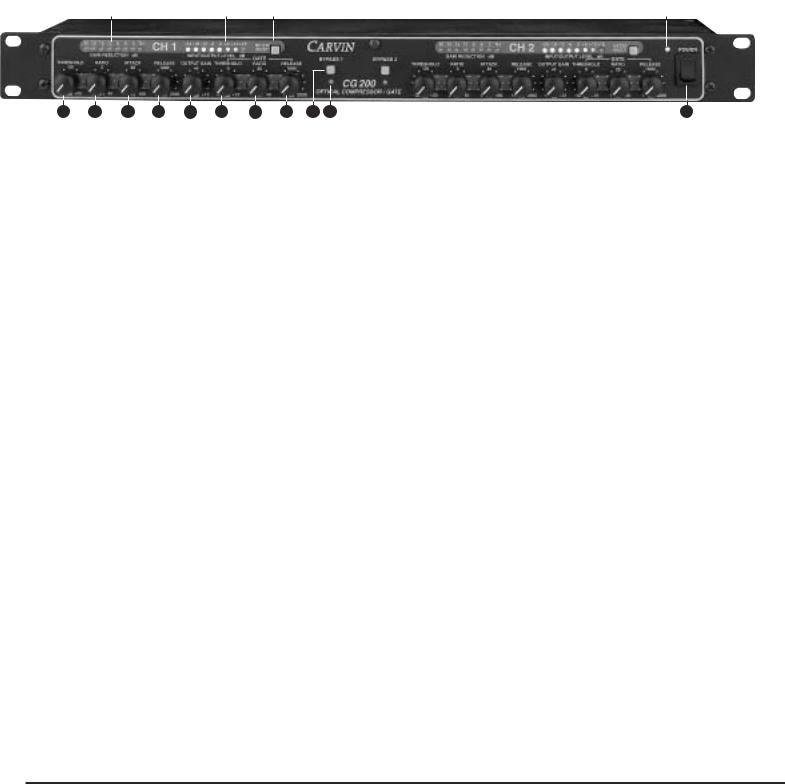
FRONT PANEL:
1. GAIN REDUCTION LED METER
Shows how much gain reduction (in dB) that is taking place whether compression, gating or both.
2. INPUT/OUTPUT LED METER
Shows the incoming signal or output signal level (in dB) depending
on the position |
meter in/out switch. |
3. METER IN/OUT |
|
When this switch |
“IN”, the input/output meter shows the input |
signal level. When |
the meter shows output level. |
4. BYPASS SWITCH |
|
With this switch |
the signal passes with no processing. Note: |
The OUTPUT GAIN knob will still control the output level even when the CG200 is set bypass.
5. BYPASS INDICATOR
This LED illuminates when the unit is bypassed.
6. POWER INDICATOR
This LED illuminates when power to the unit is on.
7. POWER SWITCH
Push this switch the "ON" position to apply power to the unit. The power indicator LED will light to show the CG200 is on.
8. THRESHOLD
The THRESHOLD the signal level where compression begins. All incoming signals above this threshold will be compressed
according to the |
control. If no compression is desired, and |
use of the gate |
desired by itself, turn the THRESHOLD control |
clockwise to "OFF" |
|
9. RATIO: |
|
The RATIO is the |
of compression applied to the signal above |
the threshold setting. The numbers 2 through 20 are the dB of input signal required a 1 dB output increase. 2:1 is the most
subtle. 20:1 is the most extreme and will produce a more "squashed" sound. High ratio settings can be used for limiting.
10. ATTACK:
Delay (in milliseconds) is “before compression takes place.” A short attack time will respond much faster to signal dynamics than a longer setting. Increase this setting if you want the initial hit from a snare or punch from a bass to get through before compressing the signal.
11. RELEASE:
Time (in milliseconds) in which compression is held after the initial attack. The shorter the release time, the closer the compressor follows the signal dynamics. Longer release times will tend to make the sound more "squashed".
12. OUTPUT GAIN:
Output signal level. Use this after setting the compressor to make up the over all signal level lost due to compression.
13. GATE THRESHOLD:
Signal level where “gating begins.” All incoming signals below this threshold will be attenuated according to the GATE RATIO control. Any signals above this threshold will be passed unaffected (unless compression is on). If no gating is desired, turn this control fully counter clockwise to the "OFF" position.
14. GATE RATIO:
Amount of attenuation applied to the signal below the gate threshold level. Setting the GATE RATIO to 1:1 will effectively turn gating off. A setting of 30:1 will attenuate all incoming signals below the gate threshold by 30dB.
15. GATE RELEASE:
Amount of time after signal reaches the Gate Threshold before gating turns on. The shorter the setting, the more "choppy" and tighter the effect. The longer the time, the smoother the effect but the more un-wanted noise will pass.
Compressor/Gate Applications
COMPRESS A STEREO MIX
CONNECTION METHOD: STEREO L-R MIX (see fig. 1)
To compress a stereo mix, depress the STEREO LINK button. Start with a low RATIO setting. Set the THRESHOLD for a bit of Gain Reduction and set the ATTACK on a slow setting. Raise the RATIO for more compression if needed.
EVEN OUT VARIOUS VOCAL MICS
CONNECTION METHOD: CHANNEL INSERT (see fig. 2)
In a situation where there are various vocalists with different dynamics, it is best to compress each mic channel before adding each mic to the mix. Start with a medium ATTACK setting on each mic. Set the RELEASE time
to a slow setting. Set the compression RATIO to 4:1. Set the THRESHOLD so the GAIN REDUCTION meters show 9dB of gain reduction. Increase the compression RATIO as needed. Soft vocal signals may require a higher RATIO setting.
BASS GUITAR, ELECTRIC GUITAR COMPRESSION CONNECTION METHOD: CHANNEL INSERT (see fig. 2)
To increase Bass sustain and reduce transient spikes, set the compression RATIO around 4:1, set the THRESHOLD at 9dB of gain reduction. Use a higher RATIO setting (5:1 or higher) to add sustain to Guitar signals. Set the THRESHOLD as needed.
 Loading...