


CARVIN ENGINEERING DATA |
XP1000L POWERED MIXER |
OPERATING MANUAL |
MADE IN THE USA
The XP1000L mixer is Carvin’s new design to eliminate the plastic case and to offer more efficient power amps with greater tonal quality. The 3 Class D power amps are 95% efficient conserving power so they are more environmentally friendly allowing the use of small portable generators.
SUPERB SOUND is derived from the extremely low distortion, “high headroom” design. State-of-the art, low noise, balanced XLR preamps from our Concert Series mixers provide common mode rejection better than 78 dB, which means that any noise that may come over your cables is virtually eliminated. Distortion is nearly non-existent with THD below 0.1% from input to output, guaranteeing the purity of your sound. Hear the difference.
LIGHTWEIGHT and EASY TO USE Controls are logically laid out making the XP Series simple to use reducing errors during setup and performance. Its compact size and weight of only 15 lbs. makes it the lightest, most powerful mixer in its class.
3 HIGH CURRENT “GREEN” CLASS-D AMPLIFIERS produce total of 1200w RMS, 1600w peak. Class D amps not only run cooler, but their power capabilities are outstanding. The main L and R delivers 800w RMS (400w/400w) and the Monitor output delivers another 400w RMS - this kind of power maintains sonic purity while eliminating outboard power amps. Speaker outputs accept either standard 1/4” or Speakon™ connectors for secure connections with maximum power transfer to your speakers. Output meters and clip LED’s give you a visual indicator for each amp.
HIGH CURRENT “GREEN” SWITCHMODE POWER SUPPLY conserves power by operating at higher efficiency. The DC voltage supply is recharged 100,000 times per second, delivering continuous high current to the power amps.
2 INDEPENDENT 24-Bit STEREO DSP EFFECTS allow you to assign each channel to your choice of effects. You can dedicate chorus/reverb to the acoustic guitar channel and a lush reverb to the vocals, etc. Both effects are adjustable to your stage monitors so you can hear yourself with full effects. The effects processors with 256 effects each include reverbs, choruses, flanging and echoes with fully adjustable parameters for damping, decay, depth, speed, regeneration and time.
ACTIVE 3 BAND CHANNEL EQ provides easy adjustment for the tone you want. The 80Hz LO frequency control delivers a solid non-flabby bass. A simple adjustment with the MID band control brings out the best sound for vocals or guitar by affecting the very important 750Hz frequency range. The 11.5k Hz HI treble control adds sparkle to your top-end without adding harshness. Both the LO and HI controls are "shelving", which means they are effective from 20Hz to 20kHz.
THREE 7-BAND EQUALIZERS provide precise adjustments to fine tune your overall sound and to help control feedback. A stereo (dual) graphic equalizer controls the main L and R outputs and a mono equalizer controls the monitor output.
ENGINEERED TO LAST Every XP Series mixer incorporates a rugged steel chassis with protective side panels. Continuous full power is assured from high-grade 6063-T5-aluminum heat sinks cooled by a variable speed fan. Sealed controls and switches guard against the outside elements while heavy-duty connectors provide a positive connection to your cables. Hidden deep in the heart of these mixers is the “SMT” Surface Mount Technology that utilizes surface mounted components to prevent parts from shaking or vibrating loose. Precision 1% tolerances guarantee your settings will be accurate every time. Fire retardant FR-4 military spec circuit cards feature double-sided copper to guard against noise and radio frequencies (RF). The XP Series is made in the USA for years of dependable service!
RECEIVING INSPECTION—read before getting started
INSPECT YOUR MIXER FOR DAMAGE which may have occurred during shipping. If damage is found, please notify the shipping company and CARVIN immediately. SAVE THE CARTON & ALL PACKING MATERIALS. In the event you have to re-ship your unit, always use the original carton and packing material. This will provide the best possible protection during shipment. CARVIN and the shipping company are not liable for any damage caused by improper packing.
SAVE YOUR INVOICE. It will be required for warranty service if needed in the future. SHIPMENT SHORTAGE. If you find items missing, they may have been shipped separately. Please allow several days for the rest of your order to arrive before inquiring. RECORD THE SERIAL NUMBER on the enclosed warranty card or below on this manual for your records. Keep your portion of the card and return the portion with your
name and comments to us.
USA customers register online at: www.carvin.com/registration
All other countries register online at: www.carvinworld.com/registration
For your records, you may wish to record the following information.
Serial No._____________________ Invoice Date_______________
XP1000L BLOCK DIAGRAM
|
|
LEFT |
RIGHT MON EFF1 EFF2 |
|
MIC |
LEVEL |
PAN |
|
|
MIC |
THREE BAND |
|
|
|
PRE |
TONE |
|
|
|
|
CONTROLS |
|
|
|
PAD |
|
|
|
|
LINE |
|
|
TAPE OUT |
L |
GAIN |
|
EFF |
TAPE OUT |
|
|
|
LEVEL |
||
|
HI MID LOW |
1/2 |
|
R |
CHANNELS 1-6 |
MONITOR |
|
|
|
MIC |
MIC |
|
LEVEL |
|
|
|
|
PRE |
|
|
|
|
|
|
|
|
|
LEFT |
|
|
|
|
STEREO |
|
SUMMING AMP |
|
MAIN L |
L |
|
THREE BAND |
|
|
|
BALANCED OUT |
LINE |
|
TONE |
PAN |
|
|
|
|
CONTROLS |
|
|
|
|
|
INPUTS |
|
|
|
|
|
|
R |
|
|
|
MAIN |
STEREO |
|
|
|
|
|
LEVEL |
GRAPHIC |
TO INTERNAL |
|
|
|
EFF |
MUSIC |
EQUALIZER |
POWER AMPS |
|
|
|
1/2 |
|
|
|
|
|
HI MID LOW |
|
BREAK |
|
|
|
|
|
SWITCH |
|
|
|
|
|
|
|
RIGHT |
|
MAIN R |
|
|
|
|
SUMMING AMP |
|
BALANCED OUT |
|
CHANNEL 7/8 |
|
MON |
|
|
MONITOR |
|
|
|
|
|
|
BALANCED OUT |
|
|
|
|
|
GRAPHIC |
|
|
|
|
|
MONITOR |
EQUALIZER |
|
MIC |
PRE |
|
|
|
|
|
|
|
LEVEL and |
|
|
||
|
MIC |
|
LEVEL |
|
|
|
|
|
|
SUMMING AMP |
|
TO INTERNAL |
|
|
|
|
|
|
|
POWER AMP |
L |
|
STEREO |
|
|
|
|
|
THREE BAND |
|
|
|
|
|
LINE |
|
TONE |
PAN |
|
|
|
|
CONTROLS |
|
|
|
|
|
INPUTS |
|
|
|
|
|
|
R |
|
|
|
|
|
|
|
|
|
EFF |
|
|
|
|
|
|
1/2 |
|
|
|
TAPE IN |
HI MID LOW |
|
CHANNEL 9/10 |
MON |
|
RETURNS FROM |
INTERNAL |
|
INTERNAL DSP |
||
|
|
DSP INPUTS |
|
STEREO |
|
|
EFFECTS |
EFFECTS |
|
TO MAIN |
SUMMING AMP x 2 |
|
|
EXTERNAL |
|
|
SEND |
|
|
EFF 2 ONLY |
|
EFFECTS TO |
|
|
MONITOR |
|
MODEL XP1000L SPECIFICATIONS:
Frequency Response: |
Mic or Line Inputs: 20Hz-20kHz ±1dB |
Total Harmonic Distortion: |
Less than .1% at nominal levels |
Equivalent Input Noise: |
150 ohm source: -117dBu |
Output Noise: -90dBu Master Line Out
(All Levels Minimum) +20dB
Mic in to Master Line Out: 70dB Adjacent ch’s: -60db at 1KHz -78db at 1KHz
48 volt @ XLR Mic channels
5 volt, 200mA for LED lighting or MP3 charging LOW: 80Hz ±12dB
MID: 750Hz ±12dB HI: 11.5KHz ±12dB
1200w (3x400w@4ohms) 100-140VAC or 200-250VAC, 50-60Hz 10.3”H x 17”W x 10”D, 15 lbs
Optional FS22 footswitch for effects on/off CV1000
|
USB 5v Power |
12340 World Trade Drive, San Diego, CA 92128 |
|
|
|
76-88010 1009 |
|
www.carvin.com |
|
|
XP1000L CONTROLS
Quick Start Up
If you’re like most new owners, you’re probably in a hurry to plug your mixer in and use it. Here are some brief instructions to get you going quickly. With the mixer unplugged and the unit turned off, complete the following procedures:
A. CONNECTING AC POWER TO YOUR MIXER
•Start by plugging in your mixer. It will automatically select 120V-60Hz or 240V-50Hz.
•Use only a grounded (3 prong) power outlet to prevent a shock hazard (do not bypass). This gives the quietest grounding for your mixer.
B. CONNECTING INPUTS TO YOUR MIXER
•For microphones, use a XLR shielded cable and plug into the XLR MIC inputs.
•For high output devices like instruments & keyboards, plug into the LINE input jacks using a shielded cable. Adjust the channel GAIN control for mic or for instrument.
C. TURNING YOUR MIXER ON
•Set all Channel and Master LEVEL controls to their OFF positions.
•Set all HI, MID, and LOW controls and the GRAPHIC EQUALIZERS to the center “flat - no boost or cut” position.
•Adjust all “BAL” controls to their center position.
•Connect your speakers and monitors at the rear panel.
•Turn the mixer on by the rear POWER SWITCH and watch for the front POWER LED to come on. Your mixer is now
ready to operate by gradually turning up the levels.
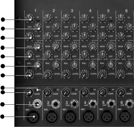
MIC CHANNEL FEATURES
1. XLR MICROPHONE INPUT
The XLR MIC input is designed for balanced low impedance microphones. The high performance, low noise preamps do a superb job of noise reduction. The XLR connector is wired as per the industry standard, pin 1 is ground, pin 2 is noninverting (positive), and pin 3 is inverting (negative). Note: Make sure the +48v phantom power is switched off before connecting or disconnecting microphones to the mixer.
2. LINE INPUT JACKS
The LINE input is a 1/4” phone jack designed for balanced or unbalanced line or instruments. Examples of these inputs would be guitar, keyboard or effect returns. The line input can be used at the same time the mic input is being used. Channels 7/8 and 9/10 feature stereo LINE INPUTS for stereo (use the top jack for mono input).
3. GAIN CONTROL (CHANNELS 1-6)
The GAIN control adjusts the input sensitivity on both the LINE and MIC input jacks over a range of 40dB. For quietest operation, set the GAIN control just below the point where the PK LED flashes. If the PK LED lights or if distortion is heard, reduce the GAIN slightly until the PK LED is off.
post-channel level, which automatically tracks the channel’s LEVEL & TONE controls. Turning this control to the left will send to the internal effects processor EFF1. Turning to the right will send to the internal effects processor EFF2 (and the external EFF 2 SND jack). Center “0” is off. Reduce these levels if the PK LEDs are flashing on the effects processors.
8. CHANNEL MONITOR CONTROL
The MON control adjusts the volume of the channel going to the master MONITOR control. The MON control is a pre-LEVEL control. This means it is unaffected by the channel LEVEL.
9-11. CHANNEL TONE CONTROLS
Each channel features active 3-band EQ tone controls LOW, MID, and HI. All three function as boost (clockwise) & cut (counter-clockwise) controls. The center 0 is the “flat” or no effect position. The LOW and HI controls are shelving type with corner frequencies at 80Hz and 11.5k Hz respectively. The MID control is a band pass type centered at 750Hz. Your settings will vary with the type of voice or instrument. Try reducing the MID to add clarity and turn up the LOW and
11
10
9
8
7
6
5
4
3
2
1
15. TAPE OUT LEVEL
The TAPE OUT LEVEL sends the MAIN signal mix to the TAPE OUT jacks for recording. The TAPE OUT level is unaffected by the MAIN level control so a recording level can be set independently of the MAIN speaker volume.
16. TAPE OUT JACKS
Use the TAPE OUT L/R jacks for recording or to send to external power amps. If the TAPE OUT is being used to record, make sure the TAPE IN jacks are not connected to the recorder output or turn the channel 9/10 LEVEL to “0” or feedback will result.
17. EFF 2 SEND JACK
The EFF 2 SEND jack can send a signal to an external processor. This is the same signal sent to the internal EFF 2 processor. Effect returns can be connected to any input channel. Make sure the EFF control for the return channel is set to “OFF” or “EFF1” or feedback will occur.
18. MAIN L-R OUTPUTS
The MAIN L/R outputs are the same signals that feed the
4. CHANNEL “PK” LED
The PK LED indicates when the channel is nearing its clipping level, causing distortion. Reduce the GAIN slightly to prevent distortion. On channels 7/8 and 9/10, reduce the level from your external souce. To get more volume, increase the master MAIN control and re-adjust your main mix.
5. CHANNEL LEVEL CONTROL
The LEVEL control adjusts the volume of the channel before going to the BALANCE control. Here is where the individual channel volumes are adjusted to make up the desired mix at the main outputs.
6. CHANNEL BALANCE CONTROL
The BAL control places the channel between Left and Right in the main stereo outputs. At the “0” center setting, the channel will be heard equally from the Left and Right outputs.
When both 1/4” jacks are used on channels 7/8 or 9/10, the BAL adjusts the L-R levels, sending signals from LINE 7/9 to the LEFT, and signals from LINE 8/10 to the RIGHT.
7. CHANNEL EFFECTS 1&2 LEVEL
The EFF 1&2 adjusts the level sent to the dual effects processor and to the front EFF SND 2 jack. The effects control is
HI for a fuller sound. Channels 7/8 and 9/10 feature stereo TONE controls.
12. TAPE IN JACKS (CHANNEL 9/10)
The L-R TAPE IN inputs on CHANNEL 9/10 are for connecting an iPod/MP3 or CD. These TAPE IN jacks can be used for returning another stereo effects processor or instrument (keyboard). Channel 9/10 inputs are NOT muted by the MUSIC BREAK switch allowing you to have background music while everything else is turned off.
MASTER SECTION FEATURES
13. MAIN LEVEL (L & R AMPS)
The MAIN control is the master volume control for all channels. The MAIN signal is sent through the MAIN L-R GRAPHIC EQ to the L and R amps and the front L/R output jacks which can be used for additional power amps, etc.
14. MONITOR LEVEL (MONITOR AMP)
The MONITOR master level is sent through the MONITOR GRAPHIC EQ to the MONITOR amp and front output jack.
internal LEFT and RIGHT amps. Use these balanced 1/4” outputs to feed additional power amps, etc..
19. MONITOR OUTPUT
The MONITOR output is the same signal that feeds the internal MONITOR amp. Use this balanced output to feed additional power amps, etc..
20. DUAL EFFECT PROCESSORS
Two 24-BIT processors provide a host of great sounding effects including Flange, Reverb, Echo, & Chorus.
The channel EFF 1 & 2 send control delivers the signals to the processors. Note: Reduce these levels if the red PEAK LEDs are flashing at the processors.
Turn up the MAIN EFFECTS control to add your effects to the L-R outputs. Adjust the SELECT and the PARAMETER to get the desired effect. Note: An audible noise will be heard while adjusting the effects.
A) ECHO: Turn SELECT for the amount of regeneration (repeats). Now turn the PARAMETER control for a shorter or longer delay time between the original signal and the echo.
 Loading...