


30GX125
Carrier 30GX125, 30GX080, 30GX115, 30GX150, 30GX136 Controls, Start-up, Operation, Service, And Troubleshooting
...
ECOLOGIC™ Air-Cooled and Fluid Cooled Chillers
Controls Start-Up, Operation,
Service, and Troubleshooting
SAFETY CONSIDERATIONS
Installing, starting up, and servicing this equipment can be
hazardous due to system pressures, electrical components, and
equipment location (roof, elevated structures, etc.). Only
trained, qualified installers and service mechanics should install, start up, and service this equipment.
When working on this equipment, observe precautions in
the literature, and on tags, stickers, and labels attached to the
equipment, and any other safety precautions that apply. Follow
all safety codes. W ear safety glasses and work gloves. Use care
in handling, rigging, and setting this equipment, and in handling all electrical components.
Electrical shock can cause personal injury and death. Shut
off all power to this equipment during installation and service. There may be more than one disconnect switch. Tag
all disconnect locations to alert others not to restore power
until work is completed.
This unit uses a microprocessor-based electronic control
system. Do not use jumpers or other tools to short out components, or to bypass or otherwise depart from recommended procedures. Any short-to-ground of the control
board or accompanying wiring may destroy the electronic
modules or electrical components.
To prevent potential damage to heat exchanger tubes
always run fluid through heat exchangers when adding or
removing refrigerant charge. Use appropriate brine solutions in cooler and condenser fluid loops to prevent the
freezing of heat exchangers when the equipment is exposed
to temperatures below 32 F (0° C).
DO NOT VENT refrigerant relief valves within a building. Outlet from relief valves must be vented outdoors in
accordance with the latest edition of ANSI/ASHRAE
(American National Standards Institute/Ame rican Society
of Heating, Refrigeration and Air Conditioning Engineers)
15 (Safety Code for Mechanical Refrigeration). The accumulation of refrigerant in an enclosed space can displace
oxygen and cause asphyxiation. Provide adequate ventilation in enclosed or low overhead areas. Inhalation of high
concentrations of vapor is harmful and may cause heart irregularities, unconsciousness or death. Misuse can be fatal.
Vapor is heavier than air and reduces the amount of oxygen
available for breathing. Product causes eye and skin irritation. Decomposition products are hazardous.
30GX080-350
30HXA,HXC076-271
50/60 Hz
Series 3
DO NOT attempt to unbraze factory joints when servicing
this equipment. Compressor oil is flammable and there is
no way to detect how much oil may be in any of the refrigerant lines. Cut lines with a tubing cutter as required when
performing service. Use a pan to catch any oil that may
come out of the lines and as a gage for how much oil to add
to system. DO NOT re-use compressor oil.
CONTENTS
SAFETY CONSIDERATIONS
GENERAL
MAJOR SYSTEM COMPONENTS
Processor Module (PSIO-1)
DSIO-HV Relay Module
Electronic Expansion Device Module
Compressor Protection Module (CPM)
PSIO-2 (8052) Module
Keypad and Display Module
(Also Called HSIO-II)
Control (LOR) Switch
OPERATION D ATA
Electronic Expansion Device (EXD)
• EXV OPERATION
• ECONOMIZER OPERATION
Oil Pumps
Motor Cooling
Back Pressure Valve (30GX and 30HXA only)
Sensors
Compressor Protection Module (CPM)
• OUTPUTS
• INPUTS
Wye-Delta vs Across-the-Line (XL)
Starting Option
Capacity Control
• MINUTES LEFT FOR START
• MINUTES OFF TIME
• LOADING SEQUENCE
• CLOSE CONTROL
• LEAD/LAG DETERMINATION
• CAPACITY SEQUENCE DETERMINATION
• MINIMUM LOAD VALVE
• CAPACITY CONTROL OVERRIDES
Head Pressure Control
• GENERAL
• AIR-COOLED UNITS (30GX)
• WATER-COOLED UNITS (30HXC)
• CONDENSERLESS UNITS (30HXA)
• 09DK CONDENSING UNITS
• ADJUSTING PID ROUTINES
. . . . . . . . . . . . . . . . . . . . . . . . . . . . . . . . . . . . . . .2,3
. . . . . . . . . . . . . . . . . . . . . . . . . . . . . 3
. . . . . . . . . . . . . . . . . . . . . . . . . . . . . 3-44
. . . . . . . . . . . . . . . . . . . . . . . . . . . . . . . . . . . . . . . . 4
. . . . . . . . . . . . . . . . . . . . . . . . . . . . . . . . . . . . 4
. . . . . . . . . . . . . . . . . . . . . . . . . . . . . . . . . . . . . . . . . . 4
. . . . . . . . . . . . . . . . . . . . . . . . . . . . . . . . 7
. . . . . . . . . . . . . . . . . . . . . . . . . . . . . . . . . 7
. . . . . . . . . . . . . . . . . . . . . . 1
. . . . . . . . . . . . . . . . . 3
. . . . . . . . . . . . . . . . . . . . . . 3
. . . . . . . . . . . . . . . . . . . . . . . . . . . 3
. . . . . . . . . . . . . 3
. . . . . . . . . . . 3
. . . . . . . . . . . . . . . . . . . . . . . . . . . . 3
. . . . . . . . . . . . . . . . . . . . . . . . . . . 3
. . . . . . . . . . . . . . 3
. . . . . 4
. . . . . . . . . . . 4
. . . . . . . . . . . . . . . . . . . . . . . . . . 10
Page
Manufacturer reserves the right to discontinue, or change at any time, specifications or designs without notice and without incurring obligations.
Book 2
Ta b 5 c
PC 903 Catalog No. 533-095 Printed in U.S.A. Form 30G,H-5T Pg 1 8-99 Replaces: 30G,H-4T

CONTENTS (cont)
Page
Cooler and Condenser (30HXC)
Pump Control
• COOLER PUMP CONTROL
• CONDENSER PUMP CONTROL
Cooler Heater Control
Oil Heater Control
Keypad and Display Module
(Also Called HSIO-II)
• ACCESSING FUNCTIONS
AND SUBFUNCTIONS . . . . . . . . . . . . . . . . . . . . . . . . 15
• AUTOMATIC DEFAULT DISPLAY . . . . . . . . . . . . . . 15
• STATUS FUNCTION . . . . . . . . . . . . . . . . . . . . . . . . . . 19
• TEST FUNCTION . . . . . . . . . . . . . . . . . . . . . . . . . . . . 27
• HISTORY FUNCTION. . . . . . . . . . . . . . . . . . . . . . . . . 27
• SET POINT FUNCTION . . . . . . . . . . . . . . . . . . . . . . . 27
• SERVICE FUNCTION . . . . . . . . . . . . . . . . . . . . . . . . . 32
• SCHEDULE FUNCTION. . . . . . . . . . . . . . . . . . . . . . . 39
Temperature Reset
• EXTERNAL TEMPERATURE RESET
• EXTERNALLY POWERED RESET
• RETURN FLUID TEMPERATURE RESET
Demand Limit
• DEMAND LIMIT (Switch Controlled, 30GX Only)
• EXTERNALLY POWERED DEMAND LIMIT
• DEMAND LIMIT (CCN Loadshed Controlled)
TROUBLESHOOTING
Checking Display Codes
Unit Shutoff
Complete Unit Stoppage
Single Circuit Stoppage
Restart Procedure
• POWER FAILURE EXTERNAL TO THE UNIT
Alarms and Alerts
Compressor Alarm/Alert Circuit
EXD Troubleshooting Procedure
• INSPECTING/OPENING ELECTRONIC
EXPANSION VALVES
• INSPECTING/OPENING ECONOMIZERS
SERVICE
Servicing Coolers and Condensers
• TUBE PLUGGING
• RETUBING
• TIGHTENING COOLER/CONDENSER
HEAD BOLTS
Inspecting/Cleaning Heat Exchangers
•COOLERS
• CONDENSERS (30HX Only)
Water Treatment
Condenser Coils (30GX Only)
• COIL CLEANING
Condenser Fans (30GX Only)
Refrigerant Charging/Adding Charge
Oil Charging/Low Oil Recharging
Oil Filter Maintenance
• REPLACING THE EXTERNAL OIL FILTER
• REPLACING THE INTERNAL OIL FILTER
Compressor Changeout Sequence
• BURNOUT CLEAN-UP PROCEDURE
Moisture-Liquid Indicator
Filter Drier
Liquid Line Service Valve
Thermistors
•LOCATION
• THERMISTOR REPLACEMENT
Pressure Transducers
• PRESSURE TRANSDUCER CALIBRATION
• TROUBLESHOOTING
Safety Devices
. . . . . . . . . . . . . . . . . . . . . . . . . . . . . . . . . . . 14
. . . . . . . . . . . . . . . . . . . . . . . . . . . 15
. . . . . . . . . . . . . . . . . . . . . . . . . . . . . . . 15
. . . . . . . . . . . . . . . . . . . . . . . . . . 15
. . . . . . . . . . . . . . . . . . . . . . . . . . . . . . 41
. . . . . . . . . . . . . . . . . . . . . . . . . . . . . . . . . . . 41
. . . . . . . . . . . . . . . . . . . . . . . . . 45-54
. . . . . . . . . . . . . . . . . . . . . . . . 45
. . . . . . . . . . . . . . . . . . . . . . . . . . . . . . . . . . . . . 45
. . . . . . . . . . . . . . . . . . . . . . . . 45
. . . . . . . . . . . . . . . . . . . . . . . . . 45
. . . . . . . . . . . . . . . . . . . . . . . . . . . . . . . 45
. . . . . . . . . . . . . . . . . . . . . . . . . . . . . . . 45
. . . . . . . . . . . . . . . . . 46
. . . . . . . . . . . . . . . . 52
. . . . . . . . . . . . . . . . . . . . . . . . . . . . . . . . . . . . . 54-68
. . . . . . . . . . . . . . 54
. . . . . . . . . . . 55
. . . . . . . . . . . . . . . . . . . . . . . . . . . . . . . . . 55
. . . . . . . . . . . . . . . . . . . 55
. . . . . . . . . . . . . . . . . . . . 56
. . . . . . . . . . . . 56
. . . . . . . . . . . . . . . . 57
. . . . . . . . . . . . . . . . . . . . . . . . . . . 58
. . . . . . . . . . . . . . 58
. . . . . . . . . . . . . . . . . . . . . . . . 60
. . . . . . . . . . . . . . . . . . . . . . . . . . . . . . . . . . . . . . . 60
. . . . . . . . . . . . . . . . . . . . . . . . 60
. . . . . . . . . . . . . . . . . . . . . . . . . . . . . . . . . . . . . 61
. . . . . . . . . . . . . . . . . . . . . . . . . . . 61
. . . . . . . . . . . . . . . . . . . . . . . . . . . . . . . . . . 64
• COMPRESSOR PROTECTION
• OIL SEPARATOR HEATERS (30GX)
• COOLER PROTECTION
Relief Devices
. . . . . . . . . . . . . . . . . . . . . . . . . . . . . . . . . . . 64
• PRESSURE RELIEF VALVES
Control Modules
. . . . . . . . . . . . . . . . . . . . . . . . . . . . . . . . . 65
• PROCESSOR MODULE (PSIO-1), COMPRESSOR
PROTECTION MODULE (CPM), HIGH VOLTAGE
RELAY MODULE (DSIO-HV), AND EXV DRIVER
MODULE (DSIO-EXV), 12/6 MODULE (PSIO-2)
• RED LED
• GREEN LED
• CONTROL MODULE BATTERY REPLACEMENT
Carrier Comfort Network (CCN) Interface
. . . . . . . . 66
• PROCESSOR MODULE (PSIO-1)
• HIGH VOLTAGE RELAY MODULE (DSIO-HV)
Replacing Defective Processor Module
Winter Shutdown Preparation
PRE-START-UP PROCEDURE
System Check
. . . . . . . . . . . . . . . . . . . . . . . . . . . . . . . . . . . 69
START-UP AND OPERATION
Actual Start-up
Operating Sequence
FIELD WIRING
. . . . . . . . . . . . . . . . . . . . . . . . . . . . . . . . . . 69
. . . . . . . . . . . . . . . . . . . . . . . . . . . . . 69
. . . . . . . . . . . . . . . . . . . . . . . . . . . . . . . . 70-75
. . . . . . . . . . . . . . . . . . . 68
. . . . . . . . . . . . . . . . . . . . 69
. . . . . . . . . . . . . . . . . . . . . 69
. . . . . . . . . . 68
APPENDIX A
(Compressor Must Trip Amps)
. . . . . . . . . . . . . 76-80
APPENDIX B
(Capacity Loading Sequence)
APPENDIX C (Available Accessories)
APPENDIX D (Building Interface)
. . . . . . . . . . . . . . 81-85
. . . . . . . . . 86,87
. . . . . . . . . . . . . 88-92
APPENDIX E (Cooler and
Condenser Pressure Drop)
. . . . . . . . . . . . . . . . . 93-96
APPENDIX F
(Typical System Components)
INDEX
START-UP CHECKLIST
. . . . . . . . . . . . . . . . . . . . . . . . . . . . . . . . . . . . . . . . . . . 99
. . . . . . . . . . . . . . . . .CL-1 to CL-8
. . . . . . . . . . . . . 97,98
GENERAL
IMPORTANT: The 30GX,HX units use refrigerant
R-134a. Compressor oil used with R-134a is Polyolester
oil.
This publication contains Start-Up, Service, Controls, Operation and Troubleshooting data for the 30GX080-350 and
30HXA,C076-271 screw chillers.
Circuits are identified as circuits A and B, and compressors
are identified as A1 or A2 in circuit A, and B1 or B2 in
circuit B.
The 30GX,HX Series chillers feature microprocessor-based
electronic controls and electronic expansion devices (EXD) in
each refrigeration circuit.
The control system cycles compressor loaders and/or compressors to mai ntain the se lected lea ving fluid te mperature s et
point. The system automatically positions the EXD to maintain
the specified refrigerant level in the cooler. The system also has
capabilities to control a condenser water valve to maintain suitable leaving-water temperature for the 30HXC unit. Safeties
are continuously monitored to prevent the unit from operating
under unsafe conditions. A scheduling function can be programmed by the user to control the unit’s occupied and unoccupied schedules. The control also operates a test function and
a manual control function that allows the operator to check output signals and ensure components are operable.
The control system consists of a processor module
(PSIO-1), an EXD driver module (DSIO-EXV), a high voltage
relay module on 30GX units (DSIO-HV), 2 six-pack relay
boards, a keypad and display module (also called HSIO-II),
2 electronic expansion devices (EXDs), 1 compressor protection module (CPM) per pair of compressors, a PSIO-2 module,
2
6 thermistors, and up to 10 transducers. A remote enhanced
display is available as an accessory.
MAJOR SYSTEM COMPONENTS
Processor Module (PSIO-1) —
upgrade to the original PSIO (8088) module, with superior
electrical noise immunity capability. It contains the operating
software and controls the operation of the machine. It has 12
input channels and 6 output channels.
The PSIO-1 continuously monitors input/output channel information received from all the modules and controls all output
signals for all output channels. It also controls the relays on the
six-pack relay board. The processor module also controls the
EXD driver module, commanding it to open or close each
EXD in order to maintain the proper cooler level. Information
is transmitted between the processor module, CPM modules,
the EXD driver module, and the HSIO-II standard display
module through a 3-wire communications bus called COMM3.
The remote enhanced display (accessory) is connected to the
PSIO-1 module through a 3-wire communications bus, but
uses a different communication bus called COMM1. The
COMM1 bus is also used to communicate to other CCN
(Carrier Comfort Network) devices when the unit is installed in
a network application.
DSIO-HV Relay Module —
4 inputs and 8 outputs and is installed on 30GX units only. The
module communicates the status of the inputs with the PSIO-1
module and operates the oil heater, outdoor fan, and minimum
load control outputs.
Electronic Expansion Device Module —
electronic expansion device module has 4 inputs and 2 outputs.
It receives signals from the PSIO-1 module and operates the
electronic expansion devices. The electronic expansion device
module also sends the PSIO-1 module the status of its 4 input
channels.
Compressor Protection Module (CPM) —
compressor protection module monitors the high pressure
switch status, running current, and motor temperature for each
compressor. Each CPM controls up to 2 compressors. The
CPM also controls the motor cooling solenoid, oil solenoid,
and contactor outputs. A pre-punched configuration header for
each compressor determines the must trip amps setting. Each
CPM sends the PSIO-1 each compressor’s motor temperature,
relay status, and running current as a percentage of the must
trip amps value. The CPM als o communic ates any al arm conditions as the feedback value.
PSIO-2 (8052) Module —
put/output module only, as there is no unit software loaded in
the module. This module has 12 input channels and 6 output
channels.
This module is an
The DSIO-HV module has
The
The
This module is used as an in-
Keypad and Display Module (Also Called
HSIO-II) —
keys, 4 operative keys, 12 numeric keys, and a 2-line
24-character alphanumeric LCD (liquid crystal display). Key
usage is explained in the Accessing Functions and Subfunctions section on page 15.
Control (LOR) Switch —
fined by the position of the LOCAL/OFF/REMOTE (LOR)
switch. This is a 3-positi on manual swit ch th at allow s th e chiller to be put under the control of its own controls (LOCAL ),
manually stopped (OFF), or controlled through a set of remote
contacts (REMOTE). This switch i s different than the switch
This device consists of a keypad with 8 function
Control of the chiller is de-
that is used in the Flotronic™ II controls configuration. The
CCN control is enabled through the H SIO-II. The switch allows unit operation as shown in T able 1.
In the LOCAL position, the c hiller i s allowed to ope rate and
respond to the scheduling configuration, CCN configuration,
and set point data. In the remote position, the unit operates similarly to the LOCAL position, except the remote contacts must
be closed for the unit to operate.
Table 1 — Unit Mode from LOR Switch
and CCN State
SWITCH
POSITION
LOCAL
OFF
REMOTE
CCN —
NR —
NOTE: If the unit is configured for a clock, then the unit is under clock control if it is in an
ON mode.
REMOTE
CONTACTS
NR
NR NR NR LOCAL OFF
OPEN NR NR LOCAL OFF
CLOSED
LEGEND
Carrier Comfort Network
Input Not Read by Processor
CCN
CONFIGURATION
DISABLE NR LOCAL ON
ENABLE
DISABLE NR LOCAL ON
ENABLE
CCN
STATE
RUN CCN ON
STOP CCN OFF
RUN CCN ON
STOP CCN OFF
UNIT
MODE
OPERATION DATA
Electronic Expansion Devi ce (EXD) —
processor controls the EXD through the EXD driver module .
The EXD will either be an EXV (electronic expansion valve) or
an economizer. Inside both these devices is a linear actuator stepper motor.
EXV OPERATION — High-pressure liquid refrigerant enters the valve through the bottom. A series of calibrated slots
are located inside t he orifice assembly. As refrigerant passes
through the orifice, the pressure drops and the refrigerant
changes to a 2-phase condition (liquid and vapor). To control
refrigerant flow for different operating conditions, the sleeve
moves up and down over the orifice, thereby changing orifice
size. The sleeve is moved by a linear stepper motor. The stepper motor moves in increments and is controlled directly by the
processor module. As the stepper motor rotates, motion is
transferred into linear movement by the lead screw. Through
the stepper motor and lead screw, 1500 discrete steps of motion
are obtained. The large number of steps and long stroke result
in very accurate control of refrigerant flow.
Each circuit has a liquid level sensor mounted vertically in
the top of the cooler shell. The level sensor consists of a small
electric resistance heater and 3 thermi stors wire d in s eries , positioned at different heights inside the body of the well. The
heater is designed so that the thermistors read approximately
200 F (93.3 C) in dry air . As the refrigerant level ris es (falls) in
the cooler, the resistance of the closes t thermistor(s) will increase (decrease) as it is cooled by the rising liquid refrigerant
(heated by the heater). This large resistance difference allows
the control to accurate ly maint ain a spe cified le vel.
The level sensor monitors the refrigerant liquid level in the
cooler and sends this infor mation to the PSIO-1. At initia l startup, the EXV position is at zero. After that, the microprocessor
keeps accurate track of the valve position in order to use this information as input for the other control functions. The processor does this by initializing the EXVs at start-up. The processor
sends out enough closing pulses to the valve to move it from
fully open to fully closed, then resets the position counter to zero. From this point on, until the next initialization, the processor counts the total number of open and closed steps it has sent
to each valve.
The micro-
3

ECONOMIZER OPERATION — Economizers are factory
installed on 30GX105-350 units and 30HXA,C161-271 units.
All other sizes use standard EXVs. The economizer improves
both the chiller capacity and efficiency as well as providing
compressor motor cooling. Inside the economizer are both a
linear stepper motor (same as standard EXV motor) and a float
valve. The stepper motor is controlled by the processor to
maintain the desired liquid level in the cooler (as is done for
chillers without economizers). The float valve maintains a liquid level in the bottom of the economizer.
Liquid refrigerant is supplied from the condenser through
the end to the bottom of the economizer. A bubbler tube supplies a small amount of discharge gas to ensure that the float
will be able to work properly. As the refrigerant passes through
the EXD, its pr essure is reduced to an inter mediate level of
about 75 psig (517 kPag). This pressure is maintained inside
the economizer shell. Next, the refrigerant flows through the
float valve where its pressure is further reduced to slightly
above the pressure in the cooler.
The increase in performance is achieved when some of the
refrigerant passing through the EXD flashes to vapor, further
subcooling the liquid that is maintained at the bottom of the
economizer. This increase in subcooling provides additional
capacity. Also, since the additional power required to accomplish this is minimal, the efficiency of the m achine improves.
The vapor that flashes rises to the top of the economizer where
it passes to the compressor and is used to provide motor cooling. After passing over the motor windings, the refrigerant
reenters the cycle at an intermediate port i n the compression
cycle.
Oil Pumps —
nally mounted prelubricating oil pump per circuit. This pump
is operated as part of the start-up sequence. On 30GX units, the
pumps are mounted to the base rails on the oil separator side of
the unit. The pumps are mounted to a bracket on the condensers of 30HXC units and to the oil separator on 30HXA units.
When a circuit is required to start, the controls energize the
oil pump first and read the oil pressure transducer reading. The
pump is operated for a period of 20 seconds, after which the oil
solenoid is energized to open the oil inlet valve at the compressor. The control again reads the pressure from the oil pressure
transducer. If the pump has built up sufficient oil pressure, the
compressor is allowed to start.
Once the compressor has started, the oil pump is turned off
within 10 seconds. If the pump is not able to build up enough
oil pressure, the pump is turned off. Within 3 seconds, the
pump is re-energized and makes one additio nal attempt to build
oil pressure. The control generates an alarm if the second attempt fails.
The oil pump is also used to supplement system pressure
under certain operating conditions. The oil flow requirements
of the compressor vary based on pressure differential across the
compressor. The oi l pump is designed to provi de differential oil
pressure during low pressure differential conditions. It is not
designed to overcome high pressure drop across filters during
high pressure differential conditions.
If the differential oil pressure (oil pressure – economizer
pressure) for a compressor is less than 13 psi then the oil pump
will be started. Just before the oil pump is started the control
measures the pressure differential between the discharge pressure and oil pressure (oil system pressure drop). The oil system
pressure drop is saved and used to determine when the oil
pump should be shut off.
When the oil pump is operating, it is capable of increasing
oil pressure from 0 psi to 50 psi depending on the oil flow
The 30GX,HX screw chillers use one exter-
requirements of the compressor. For example, if the compressor needs 2 gpm (high pressure differential condition) and the
oil pump is capable of 1.2 gpm, there is no pressure rise and the
oil flow will bypass the check valve and supply the 2 gpm to
the compressor. If the compressor requires .75 gpm, the oil
pump will increase pressure to satisfy the oil pressure requirement.
The pump will continue to operate until the discharge pressure minus economizer pressure is greater then 17 psi plus the
oil system pressure drop.
Example:
Discharge pressure 80 psi
Oil pressure 65 psi
Oil system pressure drop80 –65 = 15 psi
Economizer pressure 55 psi
Suction pressure 42 psi
Based on the above conditions the oil pump will be started
because differential oil pressure equals 10 psi.
The oil pump will continue to operate until the discharge
pressure minus economizer pressure (which equals 25) is
greater than 17 plus 15 (oil system loss before pump was started). The only way this can be satisfied is if the discharge pressure increases or the compressor unloads at which point the oil
pump will be shut off.
Motor Cooling —
tures are controlled to a set point of 200 F (93.3 C). The control
accomplishes this by cycling the motor cooling solenoid valve
to allow liquid refrigerant to flow across the motor windings as
needed. On units equipped with economizers, flash gas leaves
the top of the economizer and continually flows to the motor
windings. All refrigerant used for motor cooling re-enters the
rotors through a port located midway along the compression
cycle and is compressed to discharge pressure.
Compressor motor winding tempera-
Back Pressure Valve (30GX and 30HXA
only) —
30GX units and mounted on the oil separator shell of 30HXA
units. The valve’s function is to ensure that there is sufficient
system differential pressure to allow for oil to be driven back to
the compressor. A small copper line (economizer pressure) is
connected to the top of the valve, which contains an internal
spring that closes a piston if the pressure in the oil separator is
not at least 15 psig greater than the economizer pressure.
Sensors —
Flotronic™ II chiller control system) gathers information from
sensors to control the operation of the chiller. The units use up
to 10 standard pressure transducers, up to 8 standard thermistors (including 4 motor temperature thermistors), and 2 liquid level thermistors to monitor and control system operation.
The sensors are listed in Table 2.
Compressor Protection Module (CPM) —
CPM controls up to 2 compressors. The CPM provides the following functions:
• compressor main contactor control|
• Wye-Delta contactor transition
• compressor ground current protection
• motor temperature reading
• high-pressure protection
• reverse rotation protection
• current imbalance protection
• compressor oil solenoid control
• motor cooling solenoid contro l
• sensor bus communications
• starting and running overcurrent protection
This valve is located on the oil separator outlet on
The 30GX,HX control system (based on the
One
4
The CPM has the following 4 output relays and 4 inputs:
OUTPUTS:
• compressor contactor
• compressor oil solenoid
• compressor motor cooling soleno id
• Wye-Delta transition relay
INPUTS:
• motor temperature
• three-phase current
• high-pressure switch
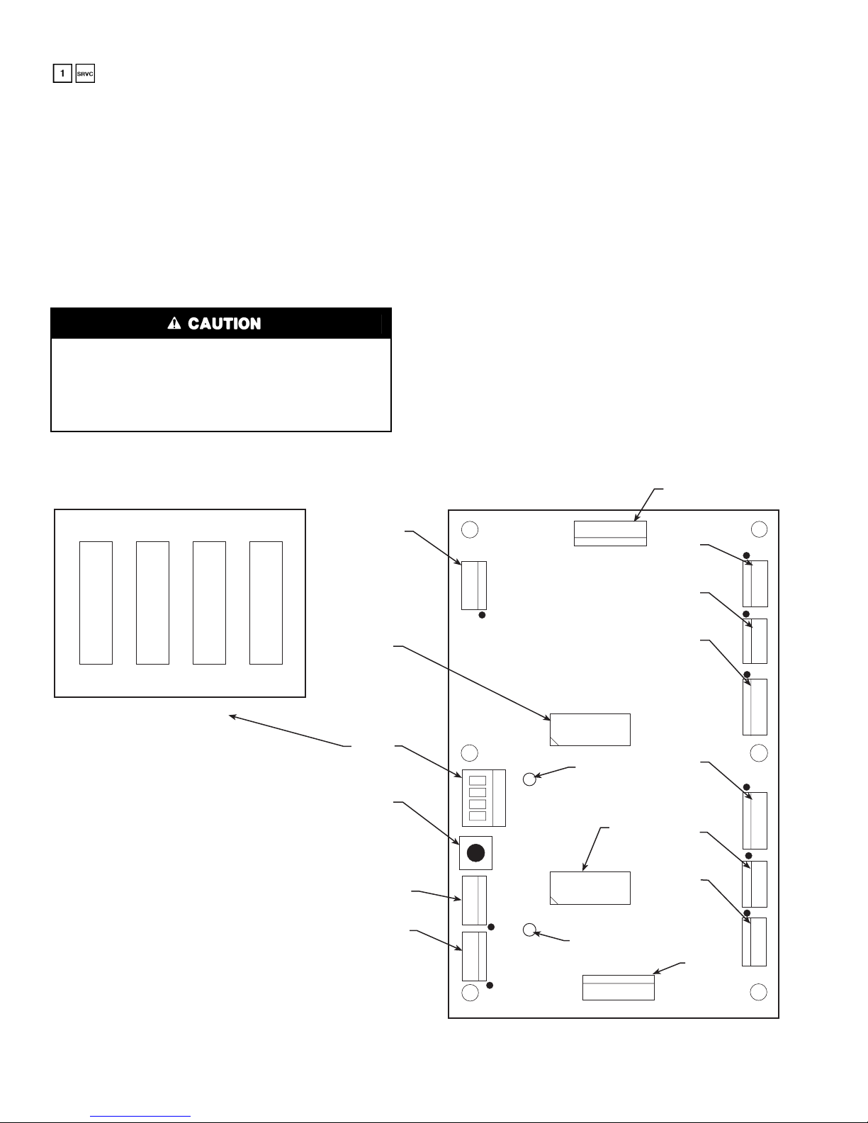
A diagram of the CPM board is (HN67LM101) shown in
Fig. 1. One CPM board is installed on 30GX080-176 and
30HXA,C076-186 units, and 2 CPM boards are installed on
30GX205-350 and 30HXA,C206-271 units. The address for
switches 3 and 4. For CPM1 (compressors A1 and B1), both
DIP switches should be set to 0. For CPM2 (compressor A2,
for 30GX205-265 and 30HXA,C206-271 units only and compressors A2 and B2 for 30GX281-350 only), both switches
should be set to 1. See Table 3 for CPM board connections.
The CPM has a reset button located between the DIP switch
and the J10 connector. Pressing the reset button on the CPM
will clear any current CPM alarms, but will not turn off any
outputs from the CPM. Pressing the reset button on the CPM
will NOT cause the board to go through initialization. Initialization period only occurs during power-up and lasts for approximately 2 minutes. Each compressor’s MTA (must trip
amps) setting is communicated to the PSIO-1 during the initialization period. Switches 1 and 2 should be set to 0. See Table 4
for DIP switch settings.
each CPM board is set using DIP (dual in-line package)
Table 2 — Thermistor and Transducer Locations
Sensor Description Location Connection Terminals
T1
T2
Motor Temp A1
Motor Temp A2*
Motor Temp B1
Motor Temp B2†
T5
T6
LL-A (T3)
LL-B (T4)
T7 (optiona l)* *
STP (optional)**
T8 (optiona l)* *
T9 (optiona l)* *
Sensor Description Location Connection Terminals
DPT-A
SPT-A
EPT-A
OPT-A1
OPT-A2*
DPT-B
SPT-B
EPT-B
OPT-B1
OPT-B2†
*30HX206-271 and 30GX205-265 only.
†Sensors are available as accessories for field installation.
Cooler Leaving Fluid Temp Cooler Head Leaving Fluid Side PSIO-2, J7 pins 2,3
Cooler Entering Fluid Temp Cooler Head Entering Fluid Side PSIO-2, J7 pins 5,6
Motor Temperature A1 Compressor A1 Junction Box CPM1, plug J5
Motor Temperature A2 Compressor A2 Junction Box CPM2, plug J5
Motor Temperature B1 Compressor B1 Junction Box CPM1, plug J9
Motor Temperature B2 Compressor B2 Junction Box CPM1, plug J9
Discharge Gas Temp A Top of Oil Separator Circuit A PSIO-2, J7 pins 8,9
Discharge Gas Temp B Top of Oil Separator Circuit B PSIO-2, J7 pins 11,12
Liquid Level Circuit A Top of Cooler Circuit A PSIO-1, J7 pins 5,6
Liquid Level Circuit B Top of Cooler Circuit B PSIO-1, J7 pins 8,9
Outdoor Air Thermistor Outside Air Stream PSIO-2, J7 pins 20,21
Space Temperature Conditioned Space PSIO-2, J7 pins 23,24
Condenser Entering Water Thermistor Condenser Entering Fluid Line PSIO-2, J7 pins 14,15
Condenser Leaving Water Thermistor Condenser Leaving Fluid Line PSIO-2, J7 pins 17,18
Discharge Pressure Circuit A Top of Condenser Separator Circuit A PSIO-1, J7 pin 22
Suction Pressure Circuit A Top of Cooler Circuit A PSIO-1, J7 pin 19
Economizer Pressure Circuit A Economizer Line Entering Comp A PSIO-1, J7 pin 10
Oil Pressure Compressor A1 Compres sor A1 Oil Connection PS IO-1, J7 pin 25
Oil Pressure Compressor A2 Compres sor A2 Oil Connection PS IO-1, J7 pin 1
Discharge Pressure Circuit B Top of Oil Separator Circuit B PSIO-1, J7 pin 16
Suction Pressure Circuit B Top of Cooler Circuit B PSIO-1, J7 pin 31
Economizer Pressure Circuit B Economizer Line Entering Comp B PSIO-1, J7 pin 13
Oil Pressure Compressor B1 Compres sor B1 Oil Connection PS IO-1, J7 pin 28
Oil Pressure Compressor B2 Compres sor B1 Oil Connection PS IO-1, J7 pin 16
THERMISTORS
PRESSURE TRANSDUCERS
Table 3 — Compressor Protection Module
(CPM) Plug Connections
CPM PLUG DESCRIPTION
J1
J2, J6
J3, J7
J4, J8
J5, J9
J10, J11
NOTE: Plugs J2-J5 are for compressors A1 (CPM1) or A2 (CPM2).
Plugs J6-J9 are for compressor B1 (CPM1) or B2 (CPM2).
24-vac Power Input
Compressor Contactor(s)
High Pressure Switch, Oil and Motor Cooling
Solenoids
Current Sensor Input
Compressor Motor Temperature Input
Communication Connections
30GX080-176
30HXA076-186
30HXC076-186
30GX205-350
30HXA206-271
30HXC206-271
5
Table 4 — CPM Address DIP Switch Settings:
UNIT
CPM1 CPM2
1234 1 2 3 4
0000————
0000 0 0 1 1
To verify proper must trip amps header configuration, press
and use the up arrow key on the HSIO to locate the
must trip amp values. Press the reset button on the control panel to update these values. See Appendix A. If the values do not
match those in Appendix A, verify that the configuration headers have been properly punched out.
The CPM communicates on the COMM3 communic ation
bus to the PSIO-1 module. Proper operation of the CPM board
can be verified by observing the 2 LEDs (light-emitting diodes)
located on the board. The red LED blinks at a rate of once every 1 to 2 seconds. This indicates that the module is powered
and operating correctly. The green LED blinks when the module is satisfactorily communicating with the PSIO-1 module.
The CPM communicates the status of its inputs and outputs,
and reports 15 different alarm conditions to the PSIO-1. The
alarms are listed in Table 5.
The CPM module has many features that are specifically
designed to protect the compressor, including reverse rotation protection. Do not attempt to bypass or alter any of the
factory wiring. Any compressor operation in the reverse
direction will result in a compressor failure that will require
compressor replacement.
The PSIO-1 will generate an alert when it receives an alarm
input from the CPM. The alert will be generated in a y.xx format, where “y” refers to the compre ssor and “xx” to the alarm
value in Table 5 (decimal point removed). For example, the
HSIO might display Alarm 1.75 for a contactor failure occurring on compressor A1. Similarly, the display would read 5.85
for a motor overtemperature condition on compressor B1.
Alerts for compressors A2 and B2 (if present) would be generated as “2.xx” and “6.xx,” respectively. Alarm codes 3 and 4
would not be used. Ending zeros are not displayed.
The high-pressure switch is wired in series with the relay
coils of the 8 relays on the CPM. If this switch opens during
operation, all relays on the CPM are deenergized and the compressor is stopped. The failure is reported to the PSIO-1 and the
processor module locks off the compressor from restarting until the alarm is manually reset.
1
0
SW1
LEGEND
LED —
MTA —
NOTES:
1. The red LED blinks continuously when the module
is operating properly.
2. The green LED blinks continuously when communicating properly with PSIO-1.
3. On all plugs, pin 1 is identified by a “●.’’
1
0
SW2
Light-Emitting Diode
Must Trip Amps
1
00
SW3 SW4
1
COMP 2
MTA
HEADER
DIP
SWITCH
RESET
BUTTON
J1
J10
J11
3
2
1
3
2
1
3
2
1
1
2
3
4
8
8
GREEN LED
12
3
RED LED
5
4
5
4
1
COMP 1
MTA
HEADER
1
2
3
1
J7
J6
1
J9
J8
J4
J5
J2
J3
2
3
1
2
3
1
2
3
4
1
2
3
4
1
2
3
1
2
3
Fig. 1 — Compressor Protection Module (HN67LM101)
6
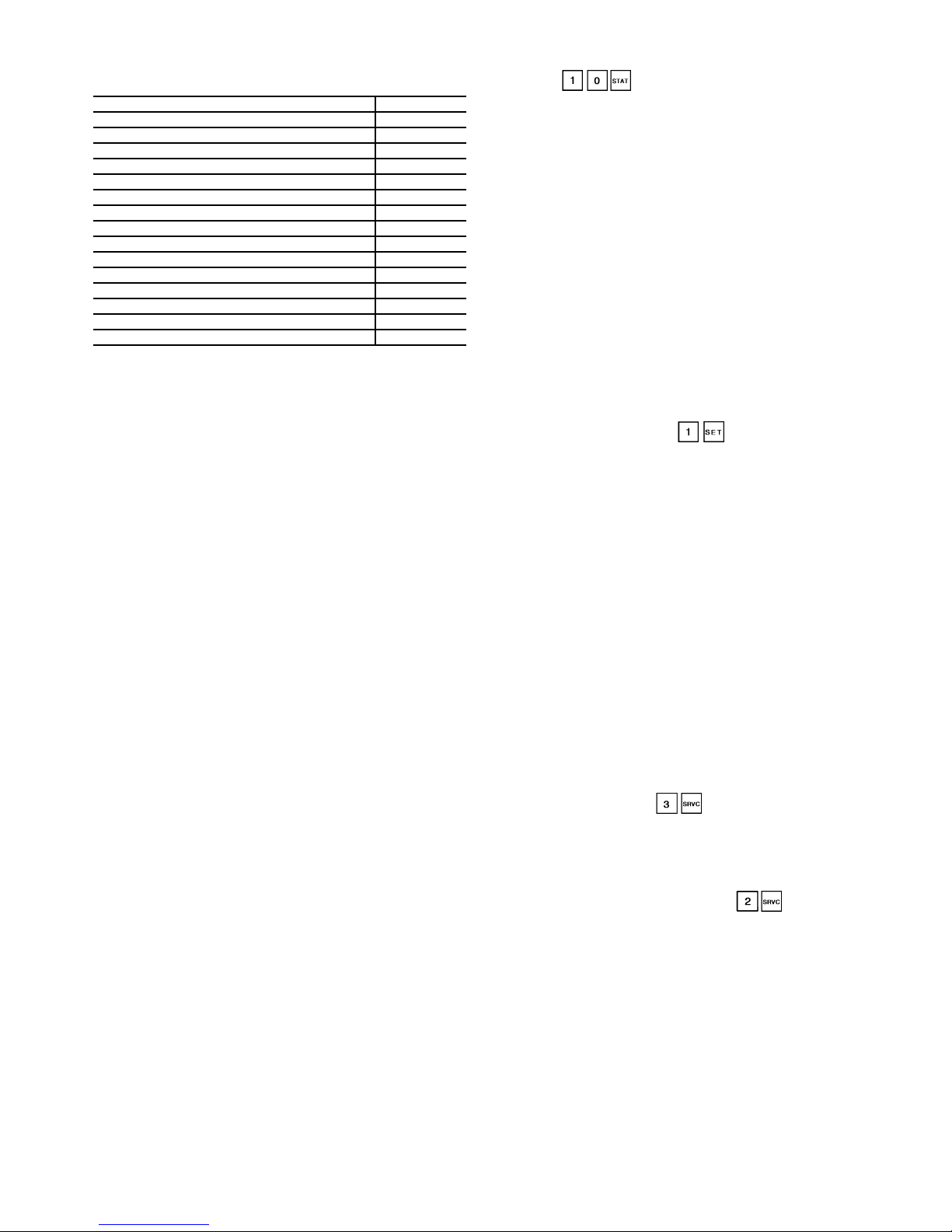
Table 5 — Compressor Protection Module
Feedback Codes
High Pressure Switch Trip 1.0
No Motor Current 2.0
Current Imbalance Alarm 10% 2.5
Current Imbalance Warning 10% 2.7
Current Imbalance 25% 3.0
Single Phase Current Loss 3.5
High Motor Current 4.0
Ground Fault 5.0
Contactor Failure 7.5
Current Phase Reversal 8.0
Motor Overtemperature 8.5
Open Thermistor 9.0
Configuration Header Fault 9.5
Shorted Thermistor 10.0
No Error 0
ALARM CONDITION VALUE
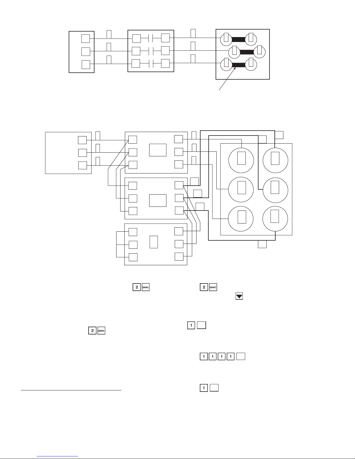
Wye-Delta vs Across-the-Line (XL) Starting
Option —
208/230-3-60 or 230-3-50 (5 or 8 at Position 12 in model number) are supplied with factory installed Wye-Delta starters. All
other voltage options can be ordered with either Wye-Delta or
XL starting options. The XL starting method is the most cost
effective and simply starts the compressor motor in a Delta
configuration (the motors are designed for continuous operation in this configuration) using a single contactor. See Fig. 2.
This is the simplest starting method to use and is ideal where
starting current does not require limiting.
Where current limitations exist, the Wye-Delta option may
be used. See Fig. 3. This option uses a factory-installed starter
assembly for each compressor, which consists of 3 contactors
labelled 1M, 2M, and S. As the compressor is started, the CPM
module energizes contactors 1M and S, which connects and
energizes the motor windings in a Wye configuration. The
starting current required will be approximately 60% less than
that required for an XL start due to the higher impedance of the
motor windings when W ye connected. The compressor will attain about 100% of its normal operating speed (approximately
3 to 5 seconds) before the CPM module deenergizes the S contactor and energizes the 2M contactor, switching the compressor windings to a Delta wiring configuration. The S and 2M
contactors in the starter assembly are both mechanic ally and
electrically interlocked so that they will not both be energized
at the same time.
Do not alter the factory-installed power wiring from the
control box terminal block to the compressor junction block.
Doing so will cause permanent damage t o the compress or and
will require that the compressor be replaced.
Capacity Control —
pressors, loaders, and minimum load control valves to maintain
the user-configured leaving chilled fluid temperature set point.
Entering fluid temperature is used by the microprocessor to determine the temperature drop across the cooler and is used in
determining the optimum time to add or subtract capacity stages. The chilled fluid temperature set point can be automatically
reset by the return temperature reset or space and outdoor-air
temperature reset features. It can also be reset from an ext ernal
4 to 20 mA signal (requires field-supplied 500-ohm,
sistor), or from a network signal.
The capacity control algorithm runs every 30 seconds. The
algorithm attempts to maint a in the Control Point at the desired
set point. Each time it runs, the control reads the e ntering and
leaving fluid temperatures. The control determines the rate at
which conditions are changing and calculates 2 variables based
All 30GX,HX chillers operating at voltages of
The control system cycles com-
1
/2 watt re-
on these conditions. Next, a capacity ratio (Load/Unload Factor
under ) is calculated using the 2 variables to determine whether or not to make any changes to the current stages
of capacity. This ratio value ranges from –100 to + 100%. If the
next stage of capacity is a compressor, the control start s (stops)
a compressor when the ratio reaches + 100% (–100%). If the
next stage of capacity is a loader, the control energizes (deenergizes) a loader when the ratio reaches + 60% (–60%). Loaders
are allowed to cycle faster than com pressors, to minimize the
number of starts and stops on each compressor. A delay of
90 seconds occurs after each capacity step change.
MINUTES LEFT FOR START — This value is displayed in
the Status subfunction and represents the amount of time to
elapse before the unit is started. This value can be zero without
the machine running in many situations. This can include
being unoccupied, LOR switch in the OFF position, CCN not
allowing unit to start, Demand Limit in effect, no call for cooling due to no load, and alarm or alert conditions present. If the
machine should be running and none of the above are true, a
minimum off time may be in effect. The machine should start
normally once the time limit has expired.
MINUTES OFF TIME ( ) — This user configurable
time period is used by the control to determine how long unit
operation is delayed after power is applied/restored to the unit.
It is also used to delay compressor restarts after the unit has
shut off its lowest stage of capacity. Typically, this time period
is configured when multiple machines are located on a single
site. For example, this gives the user the ability t o prevent all
the units from restarting at once afte r a power fa ilure. A val ue
of zero for this variable does not mean that the unit should be
running.
LOADING SEQUENCE — The 30GX,HX compressor efficiency is greatest at full load. Therefore, the following
sequence list applies to capacity control.
1. The next compressor is not started until all others are running at 100%.
2. The second unloading stage is only used during initial
capacity staging of the unit at start-up.
3. Whenever a compressor is started i n a c ircuit , th e loaders in
the circuit are deenergized for 15 seconds before the compressor is started. The loaders are energized 90 seconds after
the compressor is started.
CLOSE CONTROL ( ) — When configured for Close
Control, the control is allowed to use any loading/capacity control devices required to maintain better leaving fluid temperature regulation. All stages of unloading are available. See
Appendix B for an example.
LEAD/LAG DETERMINATION ( ) — This is a configurable choice and is factory set to be automatic. The value
can be changed to Circuit A or Circuit B leading, as desired.
Set at automatic, the control will sum the current number of
logged circuit starts and one-quarter of the current operating
hours for each circuit. The circuit with the lowest sum is
started first. Changes to which circuit is the lead circuit and
which is the lag are made when shutting off compressors.
On 30HX206-271 and 30GX205-350 units set for staged
loading, the control fully loads the lead circuit before starting
the lag circuit and unloads the lag circuit first. When these units
are set for equal loading, the control maintains nearly equal
capacities in each circuit when the chiller is loading and
unloading.
7
TERMINAL BLOCK
21
22
23
COMPRESSOR CONTACTOR
1
2
3
L1
L2
L3
T1
1
2
T1
3
T3
JUMPER BARS
COMPRESSOR JUNCTION BOX
1
2
3
Fig. 2 — Across-the Line (XL) Compressor Wiring
6
4
5
TERMINAL BLOCK
21
22
23
1
2
3
COMPRESSOR STARTER ASSEMBLY
L1
L2
L3
L1
L2
L3
L1
L2
L3
1M
2M
S
Fig. 3 — Wye-Delta Compressor Wiring
CAPACITY SEQUENCE DETERMINATION ( ) —
This is configurable as equal circuit loading or staged circuit
loading with the default set at staged. The control determines
the order in which the steps of capacity for each circuit are
changed. This control choice does NOT have any impact on
machines with only 2 compressors.
MINIMUM LOAD VALVE ( ) — When this option is
installed and configured, the first stage of capacity is altered by
energizing the Minimum Load valve relay. Once the control
requires more capacity, the minimum load valve is deenergized
and normal capacity staging resumes with loaders and compressors. Similarly, the Minimum Load valve relay will be
energized for the last stage of capacity to be used before t he
circuit is shut down.
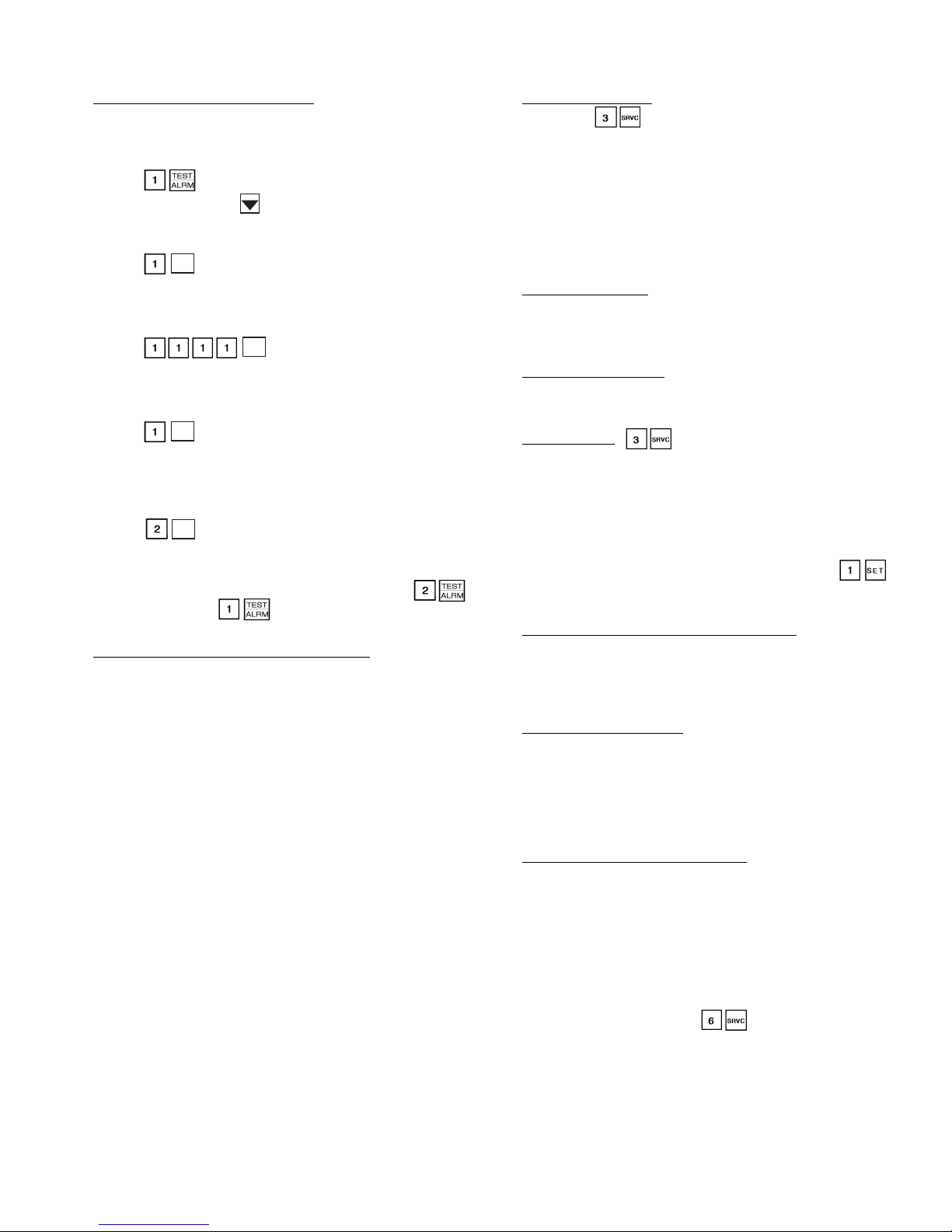
Configure Unit for Minimum Load Control
— The chiller
must be configured for minimum load control operation. This
may be done using the unit keypad (HSIO-2). Set the LOCAL/
OFF/REMOTE (LOR) switch in the OFF position.
COMPRESSOR JUNCTION BOX
T2
T3
T1
T3
T1
T1
T2
T3
T2
1
2
3
21
1
2
22
23
3
6
4
6
4
5
5
1. Press on the keypad.
2. Press the down arrow until the display reads:
MIN. LOAD V AL V E SELECT
DISABLE
3. T o enable the minimum load valve feature, press
ENTER
.
4. The display may read as follows. (If not, skip to Step 7.)
P ASSWORD PROTECTED FUNCTION
ENTER P ASSWORD
5. Press .
ENTER
6. The HSIO-2 again displays the following:
MIN. LOAD V AL V E SELECT
DISABLE
7. Press . The display changes to:
ENTER
MIN. LOAD V AL V E SELECT
ENABLE
8
The chiller is now configured for minimum load valve
control.
Test Minimum Load Relay Outputs
— After the unit is reconfigured, test the operation of the relay and solenoid valve
using the Quick Test software function. Test Circuit A as follows (the LOCAL/OFF/REMOTE (LOR) switch must be in
the OFF position):
1. Press on the HSIO-2 keypad.
2. Press the down arrow until the display reads:
MIN. LOAD V AL VE A
RELA Y IS OFF
3. Press .
ENTER
4. The display may read as follows. (If not, skip to Step 7.)
P ASSWORD PROTECTED FUNCTION
ENTER P ASSWORD
5. Press .
ENTER
6. The HSIO-2 again displays the following:
MIN. LOAD V AL VE A
RELA Y IS OFF
7. Press to energize the relay. The display reads:
ENTER
MIN. LOAD V AL VE A
RELA Y IS ON
An audible click will be heard. Verify that the solenoid valve
for Circuit A is energized.
8. Press to turn off the minimum load valve relay for
ENTER
Circuit A.
To check the operation of the solenoid valve on Circuit B,
follow the same procedure as the preceding, but enter
in Step 1, instead of . The display screens will be fo r
Circuit B instead of A.
Adjust Setting of Minimum Load Ball Valve
— The minimum load ball valve must be adjusted to suit the application.
Calibrate one circuit at a time as follows:
1. Adjust the ball valve so that it is approximately half open.
2. Operate the chiller in Manual Control mode, with one circuit
operating, and all compressor loaders deenergized. See Manual Control Mode section on page 32 for further information.
3. Record the cooler ∆T (the difference between cooler enter-
ing fluid temperature and cooler leaving fluid temperature)
at this fully unloaded condition.
4. Use the Manual Control feature to enable the minimum load
valve for the circuit that is operating.
5. Observe and record the cooler ∆T with the minimum load
valve energized.
6. Adjust the minimum load ball valve until the cooler temper-
ature difference reading from Step 5 is equal to half of the
temperature difference reading from Step 3.
7. Open the ball valve to decrease the temperature difference or
close the ball valve to increase the temperature difference
(∆T). When the valve is adjusted correctly, the difference
between cooler entering and leaving fluid temperatures
when the minimum load control is energized must be at least
half of the temperature difference when the minimum load
control is deenergized. For example, if the difference
between the cooler entering and leaving water temperature is
3° F with the valve deenergized, then the difference between
cooler entering and leaving water temperature must be at
least 1.5° F with the valve energized.
Once the outputs have been tested and the ball valve adjusted, the installation is complete. Disable manual control and
return chiller to desired operational status.
CAPACITY CONTROL OVERRIDES — The following
overrides will modify the normal operation of the routine.
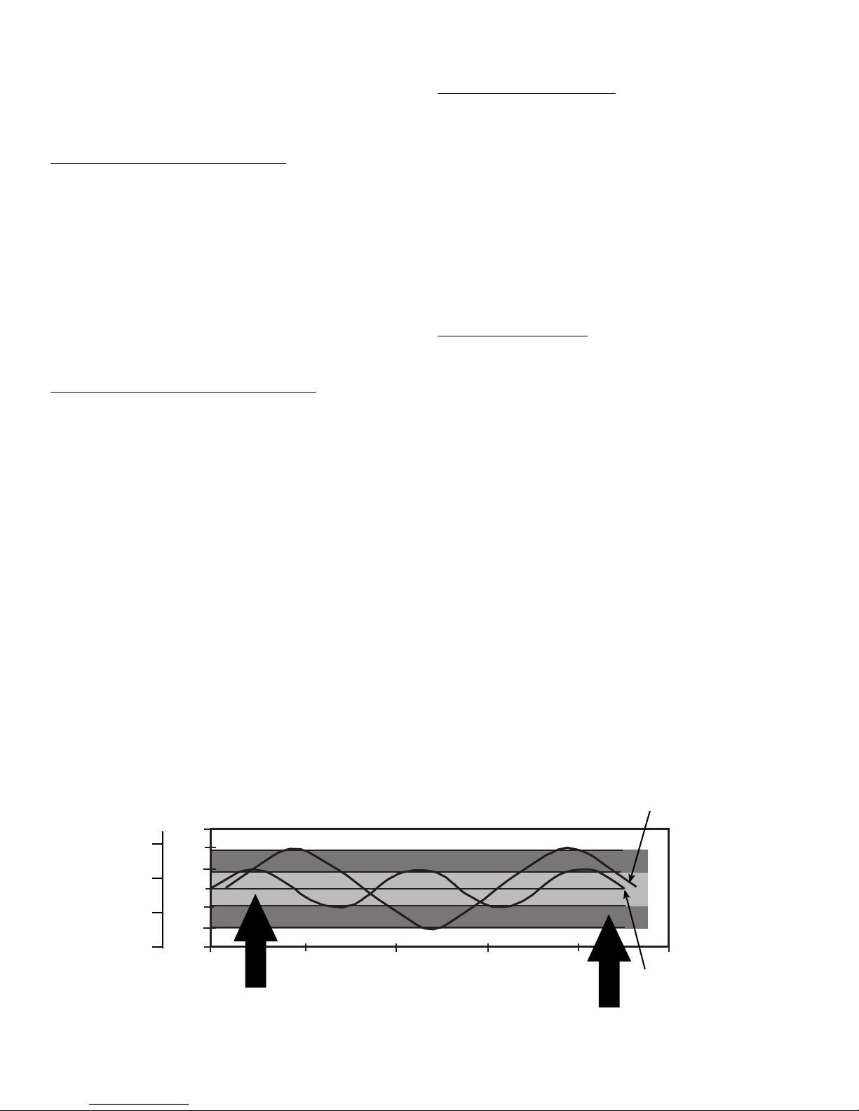
Deadband Multiplier
— The user configurable Deadband
Multiplier ( ) has a default value of 1.0. The range is
from 1.0 to 4.0. When set to other than 1.0, this factor is applied to the capacity Load/Unload Factor. The larger this value
is set, the longer the control will delay between adding or removing stages of capacity. Figure 4 shows how compressor
starts can be reduced over time if the leaving water temperature
is allowed to drift a larger amount above and below the set
point. This value should be set in the range of 3.0 to 4.0 for systems with small loop volumes.
First Stage Override
— If the current capacity stage is zero,
the control will modify the routine with a 1.2 factor on adding
the first stage to reduce cycling. This factor is also applied
when the control is attempting to remove the last stage of
capacity.
Slow Change Override
— The control prevents the capacity
stages from being changed when the leaving fluid temperature
is close to the set point (within an adjustable deadband) and
moving towards the set point.
Ramp Loading
( ) — Limits the rate of change of leaving fluid temperature. If the unit is in a Cooling mode and configured for Ramp Loading, the control makes 2 comparisons
before deciding to change stages of capacity. The control calculates a temperature difference betw een the control point and
leaving fluid temperature. If the difference is greater tha n 4° F
(2.2° C) and the rate of change (°F or °C per minute) is more
than the configured Cooling Ramp Loading value ( ),
the control does not allow any changes to the current stage of
capacity.
Low Entering Fluid Temperature Unloading
— When the
entering fluid temperature is below the control point, the control will attempt to remove 25% of the current stages being
used. If exactly 25% cannot be removed, the control removes
an amount greater than 25%, but no more than necessary. The
lowest stage will not be removed.
Low Discharge Superheat
— If a circuit’s discharge superheat
is less than 15° F (8.3° C), the control does not increase the current capacity stage. If the discharge superheat is le ss than 5° F
(2.8° C) and decreasing, the circuit is unloaded every 30 seconds until the superheat is greater than 5° F (2.8° C). The final
capacity stage is not unloaded unless an alarm condition exists.
This override is ignored for the first 3 minutes after a compressor is started.
Low Saturated Suction Temperature
— To avoid freezing the
cooler, the control will compare the cir cuit Saturated Suction
temperature with a pre determined freeze point. If the cooler
fluid selected is water, the freeze point is 28 F (–2.2 C). If the
cooler fluid selected is bri ne, the freeze poi nt is 8° F (4.4 ° C)
below the cooling set point (lower of 2 cooling set points for
dual configuration). If the saturated suction temperature is
below the freeze point, the unit capacity is not allowed to
increase.
For brine applications, the freeze point (Brine Freeze Point)
can be entered by pressing and scrolling 12 items
down. The cont rol will use the B rine Freeze Point va lue less
6° F (3.3° C) as the freeze point to compare with the Saturated
Suction temperature. The default for t he Brine Freez e Point is
34 F (1.1 C) which means the control will use 28 F (–2.2 C) as
the freeze point. The brine freeze point is adjustable from –15 F
to 34 F (–26.1 to 1.1 C).
9
For water [brine] circuits, if t he Sat urat ed Suct ion tempera ture falls below 34 F (1.1 C) [th e Brine F reeze Poi nt], the unit
capacity will not increase. If the Saturated Suction temperature
falls below 28 F (–2.2 C), [the Brine Freeze Point minus 6° F
(3.3° C)], for 90 seconds, all loaders in the circuit are turned
off. If this condition continues for a total of 3 minutes, the circuit will alarm and shut down.
High Condensing Temperature Unloading
— Every 10 seconds the control checks for the conditions below. Loaders will
be cycled as needed to control the saturated condensing temperature below the configured maximum condensing temperature. Configured maximums are 154 F (67.8 C) for 30GX,
152 F (66.7 C) for 30HXA, and 122 F (50 C) for 30HXC units.
If a circuit’s saturated condensing temperature is more than
12° F (6.7° C) below the maximum condensing temperature,
the circuit capacity is not allowed to increase. If the saturated
condensing temperature is more than 2° F (1.1° C) above the
maximum condensing temperature for 60 seconds, a loader is
turned off. If the saturated condensing temperature rises to
more than 5° F (2.8° C) above the maximum condensing temperature during the 60 seconds, a loader is turned off immediately. If all the loaders were already off, the compressor is shut
down and an alarm is generated.
MOP (Maximum Operating Pressure) Override
— The control monitors saturated condensing and suction temperature for
each circuit as well as differential oil pressure. Based on a configurable maximum operating set point (saturated suction temperature), set maximum condensing temperature, and minimum differential oil pressure, the control may reduce the number of capacity stages being used and/or may lower the EXD
position when system pressures approach the set parameters.
Head Pressure Control
GENERAL — The microprocessor controls the condenser
fans (30GX) or water val v e (30HX C ) to maintain the saturated
condensing temperature to a configurable set point. The
30HXA condenserless units with a 09DK condenser use a
combination of factory-supplied fan cycling pressure switches
(shipped in the 30HXA control box), temperature switches,
and an accessory Motormaster
50DJ902811) or Motormaster III (part no. 30GT910-079) control to control head pressure independent of 30HXA unit control. The fans are staged or speed varied (30GX) or water valve
controlled (30HXC) based on each circuit’s saturated condensing temperature and compressor status. Water cooled units
(30HXC) operating at less than 70 F (21.1 C) for entering condenser water require the use of head pressure control.
The chiller must be field configured for the options shown
in T able 6. Fan stage settings are shown in Table 7.
®
(part no. 50DJ902801 or
AIR-COOLED UNITS (30GX) — See Fig. 5 for condenser
fan locations.
Without Motormaster® Control
— The first stage of fans are
turned on based on compressor status or a Head Pressure Set
Point based on Saturated Condensing Temperature (SCT).
Additional fan stages are added when the SCT exceeds the
Head Pressure Set Point. The Head Pressure Se t Point is configurable in the Set Point subfunction. The default is 113 F
(45 C). Once a fan stage has been added, the software temporarily modifies the head pressure set point by adding 15° F
(8.3° C) for 35 seconds. A fan stage will be removed when the
Saturated Condensing Temperature has been less than the
Head Pressure Set Point minus 35 F (19.4 C) for 2 minutes.
The control uses the higher of the 2 Saturated Condensing
Temperature values for 30GX080-150 and 160 units. For the
30GX151 and 161-350 units, each circuit’s fan stages are independently controlled based on the circuit Saturated Condensing Temperature. Refer to Table 7 for condenser fan control
information. See Fig. 6A.
With Motormaster Control
— For low-ambient operation, the
lead fan in each circuit can be equipped with the optional or
accessory Motormaster III head pressure controller. If factory
installed, the controller will be configured for 4 to 20 mA control. With the Motormaster III option enabled, the PSIO-1
module calculates the required output based on Saturated Condensing temperature, Head Pressure set point, and a PID (proportional integral derivative) loop calculation. This 4 to 20 mA
output is driven through the PSIO-2 module. Proportional,
Integral, and Derivative gain parameters for air cooled controls
are adjustable and can be found in the Service subfunction.
Checkout and adjustment of the PID loop should only be
performed by certified Carrier Comfort Network technicians.
To obtain this accessory for field installation, order by part
number 30GX-900---012 for a single controller package
(30GX080-150 and 160). Order part number 30GX-900---014
for a dual controller package (30GX151 and 161-350). These
packages contain all the hardware required to install the accessory . See Fig. 6B.
The control will use the higher of the 2 Saturated Condensing Temperature values for 30GX080-150 and 160 units. For
the 30GX151 and 161-350 units, each circuit’s fan stages are
independently controlled based on the circuit Saturated Condensing Temperature. Refer to Table 8 for condenser fan staging information.
47
8
7
LWT (C)
6
5
LEGEND
LWT —
Leaving Water
Temperature
46
45
44
43
LWT (F)
42
41
0 200 400 600 800 1000
STANDARD
DEADBAND
DEADBAND EXAMPLE
TIME (SECONDS)
Fig. 4 — Deadband Multiplier
10
2 STARTS
3 STARTS
MODIFIED
DEADBAND
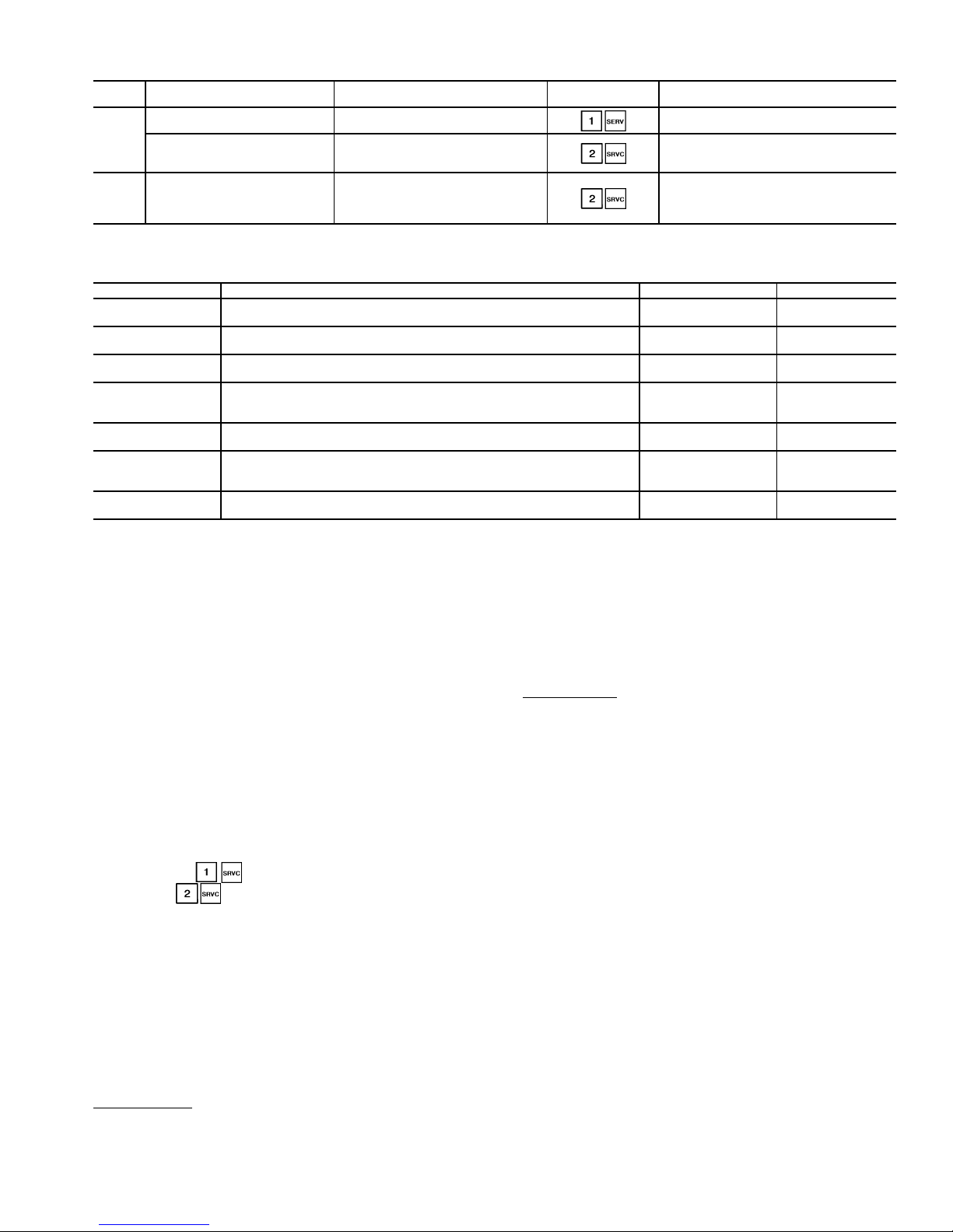
Table 6 — Field Configured Chiller Options
UNIT CONFIGURATION OPTION DESCRIPTION HSIO LOCATION FACTORY CONFIGURED?
Fan Staging Select Air cooled staging method Yes. See Table 7
30GX
30HXC
Motormaster® Control Select Applies to air cooled units only
Water Valve Type Applies to water cooled unit only
Set to 1 to enable (Motormaster only)
Set to 1 = 4 to 20 mA, 2 = 2 to 10 V,
Yes. 0 = None
Yes. 0 = None
3 = 20 to 4 mA, 4 = 10 to 2 V
Table 7 — Fan Staging Settings for Air Cooled (30GX) Units
UNIT 30GX DESCRIPTION OPTION NUMBER HSIO DISPLAY
080-105
106-125
136, 150, 160
151, 161, 175,
205, 225
176
206, 226, 250
251-350
LEGEND
SCT —
Saturated Condensing Temperature
1st stage compressor status and SCT set point
2nd stage common control based on highest SCT
1st stage compressor status and SCT set point
2nd and 3rd stage common control based on highest SCT
1st stage compressor status and SCT set point
2nd through 4th stage common control based on highest SCT
1st stage each circuit, compressor status
2nd stage Circuit B independent
2nd and 3rd stage Circuit A independent
1st stage each circuit, compressor status
2nd and 3rd stage each circuit independent
1st stage each circuit, compressor status
2nd stage Circuit B independent
2nd, 3rd and 4th stage Circuit A independent
1st stage each circuit, compressor status
2nd, 3rd and 4th stage each circuit independent
12 Com_1cmp
14 Com_2cmp
16 Com_3cmp
7 A2B1_stg
3 Ind_2stg
9 A3B2_cmp
5 Ind_3stg
WATER-COOLED UNITS (30HXC) — The 30HXC chillers
can be configured to control direct or reverse-acting water
valves that are controlled by a 4 to 20 mA signal. A 2 to10 vdc
signal can be used by installing a 500-ohm
1
/2 watt resistor
across the 2 output terminals of the 4 to 20 mA signal. The 4 to
20 mA control scheme reads the saturated condensing temperature and uses a PID (proportional integral deriative) loop to
control the head pressure. Proportional, Integral and Derivative
gain parameters for the water cooled controls are adjustable
and can be found in the Service subfunction. Checkout and
adjustment of the PID loop should only be performed by certified Carrier Comfort Network technicians.
CONDENSERLESS UNITS (30HXA) — The remote condenser fans are controlled by 2 relays with the 30HXA control
box. See Field Wiring section on page 73 for wiring details.
The 30HXA control must be configured to turn the 09DK fans
on and/or off. To set the 30HXA control for this configuration
Unit T ype under must be changed to 3 (Split System).
Next, under , Head Pressure Control Type must be
changed to 1 (Air Cooled), and Condenser Pump control must
be set to 0 (Not Controlled).
The 30HXA control does not support a 4 to 20 mA or a 2 to
10 vdc output for fan speed control. Instead, head pressure control is accomplished with fan cycling pressure switches
(09DK054-094), temperature switches (09DK044, 074-094)
and Motormaster control. Motormaster and Motormaster III
control is used with temperature sensor input to control condenser fan speed. See accessory installation instructions for
further information.
09DK CONDENSING UNITS
09DK044 Units
— The 09DK044 units have accessory provision for fully automatic intermediate-season head pressure
control through condenser fan cycling. Fan number 2 and 3
cycling is controlled by outdoor-air temperature through air
temperature switches (ATS) 1 and 2.
The air temperature switches are located in the low er divider panel underneath the coil header. The sensing element is exposed to air entering the no. 1 fan compartment through a hole
in the panel. Fan no. 1 is non-cycling.
The air temperature switch controls the fans as shown in
Table 9.
09DK054-094
— The capacity of an air-cooled condenser increases with increased temperature difference (defined as saturated condenser temperature minus entering outdoor-air temperature) and decreases with decreased temperature difference.
A drop in entering outdoor-air temperature results in a lower
saturated condensing temperature. When outdoor-air temperature drops below the minimum temperature for standard units,
additional head pressure control is required.
Model 09DK units have fully automatic intermediateseason head pressure control through condenser fan cycling
using electromechanical fan cycling controls. Standard head
pressure controls regulate the 100 and 50/50% condenser
capacity applications. Head pressure can also be controlled
by fan cycling controls supplemented by the accessory
Motormaster III solid-state head pressure control. See Motormaster
III installation instructions for more information.
In the standard control scheme, fans 1 and 2 are on when
there is a call for cooling from the respective coil circuits. Fans
1 and 2 are non-cycling. On 054 and 064 units, fans 3 and 4 are
controlled by using a fan cycling pressure switch on each of the
primary coil circuits in response to condensing pressure. On
074-094 units, fans 3 and 4 are controlled using a fan cycling
pressure switch in each of the primary coil circuits in response
to condensing pressure. Fans 5 and 6 are controlled by using
two air temperature switches, which respond to the outdoor
ambient temperature. The air temperature swit ches are locat ed
on the control box shelf.
11
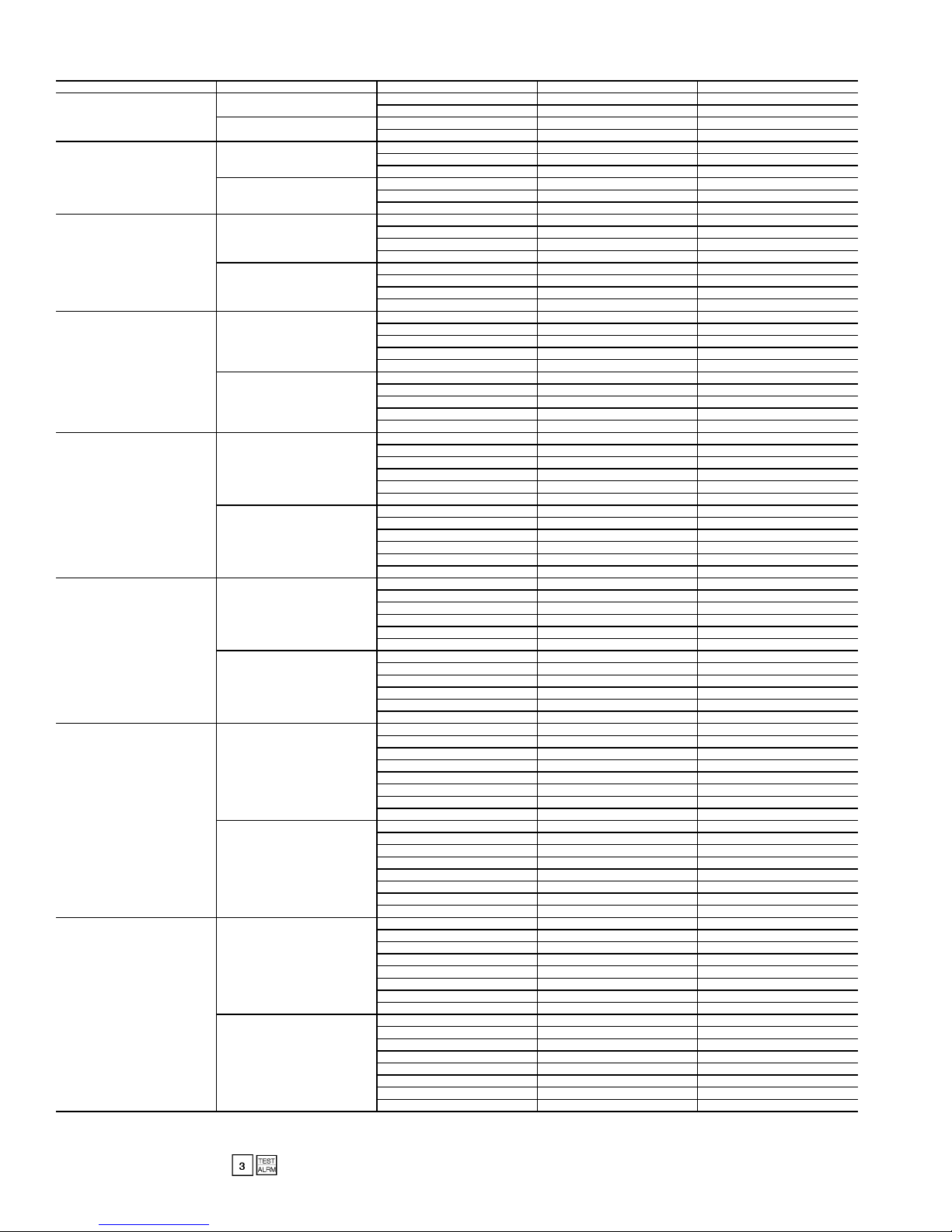
Table 8 — 30GX080-350 Condenser Fan Staging (PSIO-1 Controlled)
30GX UNIT SIZE FAN TYPE FAN CONTACTOR FANS CONTROLLED FAN RELAY NO.*
080-105
106-125
136, 150, 160
151, 161, 175, 205, 225
176
206, 226, 250
251, 265
281-350
LEGEND
Comp. —
FC —
*Fan Relay number displayed when using
Compressor
Fan Contactor
Standard
High Static
Standard
High Static
Standard
High Static
Standard
High Static
Standard
High Static
Standard
High Static
Standard
High Static
Standard
High Static
to test fans.
FC-1 1, 2 5
FC-2 3, 4 1
FC-1, 1A 1, 2 5
FC-2, 2A 3, 4 1
FC-1 1, 2 5
FC-2 3, 4 1
FC-3 5, 6 2
FC-1, 1A 1, 2 5
FC-2, 2A 3, 4 1
FC-3, 3A 5, 6 2
FC-1 1, 2 5
FC-2 3, 4 1
FC-3 5, 6 2
FC-4 7, 8 2
FC-1, 1A 1, 2 5
FC-2, 2A 3, 4 1
FC-3, 3A 5, 6 2
FC-4, 4A 7, 8 2
FC-1 1, 2 Comp. B1 contactor†
FC-2 3, 4 3
FC-3 5, 6 2
FC-4 7, 8 Comp. A1/A2 contactor†
FC-5 9, 10 1
FC-1, 1A 1, 2 Comp. B1 contactor†
FC-2, 2A 3, 4 3
FC-3, 3A 5, 6 2
FC-4, 4A 7, 8 Comp. A1/A2 contactor†
FC-5, 5A 9, 10 1
FC-1 1, 2 Comp. B1 contactor†
FC-2 3, 4 3
FC-3 5, 6 4
FC-4 7, 8 Comp. A1 contactor†
FC-5 9, 10 1
FC-6 11, 12 2
FC-1, 1A 1, 2 Comp. B1 contactor†
FC-2, 2A 3, 4 3
FC-3, 3A 5, 6 4
FC-4, 4A 7, 8 Comp. A1 contactor†
FC-5, 5A 9, 10 1
FC-6, 6A 11, 12 2
FC-1 1, 2 Comp. B1 contactor†
FC-2 3, 4 3
FC-3 5, 6 1
FC-4 7, 8 Comp. A1/A2 contactor†
FC-5 9, 10 2
FC-6 11, 12 2
FC-1, 1A 1, 2 Comp. B1 contactor†
FC-2, 2A 3, 4 3
FC-3, 3A 5, 6 1
FC-4, 4A 7, 8 Comp. A1/A2 contactor†
FC-5, 5A 9, 10 2
FC-6, 6A 11, 12 2
FC-1 2, 4 1
FC-2 6, 8 2
FC-3 1 Comp. B1 contactor†
FC-4 3 3
FC-5 5, 7 4
FC-6 9, 10 Comp. A1/A2 contactor†
FC-7 11, 12 2
FC-8 13, 14 2
FC-1, 1A 2, 4 1
FC-2, 2A 6, 8 2
FC-3 1 Comp. B1 contactor†
FC-4 3 3
FC-5, 5A 5, 7 4
FC-6, 6A 9, 10 Comp. A1/A2 contactor†
FC-7, 7A 11, 12 2
FC-8, 8A 13, 14 2
FC-1 1, 2 Comp. B1/B2 contactor†
FC-2 3, 4 3
FC-3 5, 6 4
FC-4 7, 8 4
FC-5 9, 10 1
FC-6 11, 12 Comp. A1/A2 contactor†
FC-7 13, 14 2
FC-8 15, 16 2
FC-1, 1A 1, 2 Comp. B1/B2 contactor†
FC-2, 2A 3, 4 3
FC-3, 3A 5, 6 4
FC-4, 4A 7, 8 4
FC-5, 5A 9, 10 1
FC-6, 6A 11, 12 Comp. A1/A2 contactor†
FC-7, 7A 13, 14 2
FC-8, 8A 15, 16 2
†Proper rotation of these fans to be checked when compressor(s) is running. See Fig. 5 for
condenser fan locations when viewing from the control box end.
NOTE: For 30GX151, 161-350 units, fan relays 1 and 2 energize Circuit A fans. Fan relays
3 and 4 energize Circuit B fans.
12
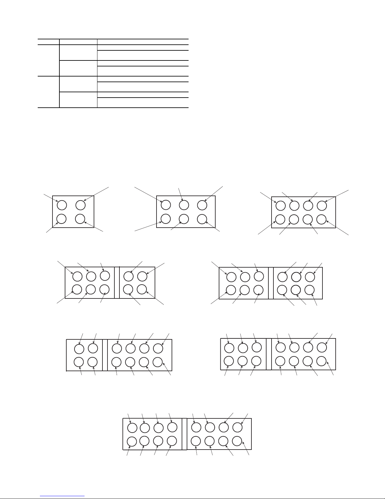
Table 9 — Air Temperature Switch Control
(09DK044 Units)
FAN FAN SWITCH TEMPERATURE
ON
FAN 2
OFF
ON
FAN 3
OFF
Above 65 ± 3 F (18.3 ± 1.7 C)
Between 55 and 65 F (12.8 and 18.3 C)
and temperature falling
Below 55 ± 3 F (12.8 ± 1.7 C)
Between 55 and 65 F (12.8 and 18.3 C)
and temperature rising
Above 80 ± 3 F (26.7 ± 1.7 C)
Between 70 and 80 F (21.1 and 26.7 C)
and temperature falling
Below 70 ± 3 F (21.1 ± 1.7 C)
Between 70 and 80 F (21.1 and 26.7 C)
and temperature rising
The fan cycling pressure switch controls the fans as follows:
Fans 3 and 4 are on above 185 ± 10 psig (1276 ± 69 kPa) and
off below 97 ± 10 psig (669 ± 69 kPa). If pressure is rising between 97 psig (669 kPa) and 185 psig (1276 kPa), fans 3 and 4
are off. If pressure is falling from 185 psig (1276 kPa) to
97 psig (669 kPa) fans 3 and 4 are on.
30GX080-105 30GX106-125 30GX136,150,160
4
2
CONTROL
BOX
END
2
4
The 09DK054-094 condensers are supplied with fan cycling pressure switches suitable for use with R-22 refrigerant.
Fan cycling pressure switches that are compatible with R-134a
refrigerant pressures are shipped with the 30HXA chillers.
These fan cycling pressure switches must be installed in place
of the 09DK factory-installed switches before charging to ensure proper head pressure control.
The air temperature switch controls th e fans as foll ows: On
the 074-094 condensers, below 70
±
3 F (21.1 ± 1.7 C) outdoor
ambient, fans 5 and 6 are off; above 80 ± 3 F (26.7 ± 1.7 C) fans
5 and 6 are on. Between 70 F (21.1 C) and 80 F (26.7 C),
whether fans 5 and 6 are on or off depends on whether temperature is rising or falling. If the temperature is rising from 70 F
(21.1 C) to 80 F (26.7 C), fans 5 and 6 are off. If the temperature is falling from 80 F (26.7 C) to 70 F (21.1 C), fans 5 and 6
are on.
6
CONTROL
BOX
END
24 6 8
CONTROL
BOX
END
1
10
9
CONTROL
BOX
END
3
1
3
5
13 5 7
30GX151,161,175,205,225 30GX176
8
7
6
5
4
3
2
CONTROL
BOX
END
1
12
7911
30GX206,226,250 30GX251,265
10
3
1
2
4
5
7
8
6
11
9
12
10
12
14
13
9
11
30GX281-350
10
16
12
14
8
6
4
2
6810
4
2
CONTROL
BOX
END
3
5
8
6
5
7
1
4
2
CONTROL
BOX
END
1
3
15
13
9
11
5
7
1
3
Fig. 5 — 30GX Condenser Fan Locations
13
CONTROL
BOX
END
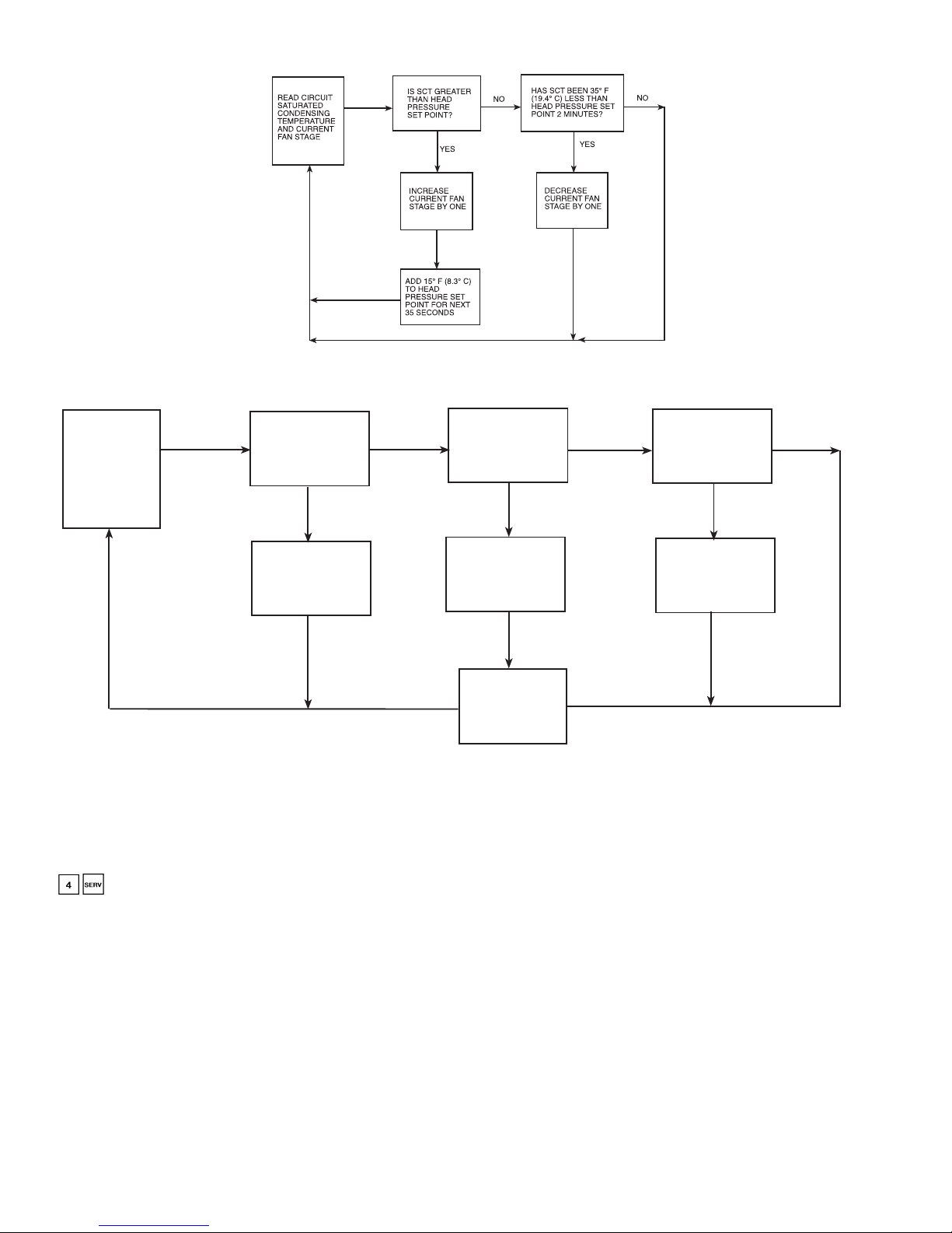
30GX UNITS — MOTORMASTER III CONTROL NOT INSTALLED
LEGEND
Saturated Condensing Temper ature
SCT —
Fig. 6A — 30GX Head Pressure Control Without Motormaster
30GX UNITS — MOTORMASTER III CONTROL INSTALLED
READ CIRCUIT
SATURATED
CONDENSING
TEMPERATURE
AND CURRENT
FAN STAGE
IS SCT GREATER
THAN HEAD
PRESSURE SET
POINT PLUS 15°F
(8.3°C)?
YES
INCREASE
CURRENT FAN
STAGE BY ONE
NO
Fig. 6B — 30GX Head Pressure Control Without Motormaster III Control
ADJUSTING PID ROUTINES — The 30GX and 30HXC
head pressure control routines use PID (proportional integral
derivative) loops to maintain a user-configurable head pressure
set point. Gain defaul t values are located in the Service function. See page 32. The current values can be read under
from the HSIO. The control calculates a new fan
speed (30GX) or water valve position (30HXC) every 5 seconds based on these gain values and an error term equal to saturated condensing temperature minus head pressure set point.
If the control routine is not responding fast enough to large
changes (circuit starting, for example), increase the proportional term.
When the routine is making too great a change to valve position or fan speed, decrease the proportional term. To minimize hunting, keep the integral term positive and as low as possible. This value is used to control “droop,” which is common
in master/submaster control schemes. The default for the derivative term is zero. The value should not need to be changed.
Cooler and Condenser (30HXC) Pump Control —
cooler and condenser (30HXC) pump control. Inputs for a
The 30GX and 30HX chillers can be configured for
®
III Control
CALCULATE NEW
PID VALUE. DOES
OUTPUT REQUIRE
MORE FANS?
YES
INCREASE
CURRENT FAN
STAGE BY ONE
OUTPUT NEW mA
SIGNAL TO
CONTROLLER
NO
DOES PID OUTPUT
REQUIRE LESS
FANS?
YES
DECREASE
CURRENT FAN
STAGE BY ONE
NO
cooler flow switch or interlock and condenser flow switch are
also provided.
COOLER PUMP CONTROL — Proper configuration of the
cooler pump control and cooler pump interlock is required to
prevent possible cooler freeze-up. The cooler pump interlock
should always be enabled. This prevents the chiller from operating unless chilled water flow is detected. See page 73 of the
Field Wiring section for proper connection of the chilled water
flow switch and cooler pump interlock.
The factory default setting for cooler pump control is “0”
(not controlled). It is recommended for 30GX packaged aircooled chillers that the cooler pump control be utilized unless
the chilled water pump runs continuously or the chilled water
system contains a suitable anti-freeze solution. The cooler
pump relay is energized when the chiller enters an occupied
mode. In the event a freeze protection alarm is generated t he
cooler pump relay is also energized. If the cooler heater is
being used and has been on for more than 15 minutes during
saturated suction freeze protection, the cooler pump relay is
energized.
When the cooler pump control is set to “0” and the cooler
pump interlock is set to “1” an alarm 53 will be generated if
flow is not proven within one minute after the unit is enabled
and in an occupied mode.
14
When the cooler pump control is set to “1” and the cooler
CLEAR
ENTER
1
2
3
4
5
6
7
8
9
0
.
-
STAT
SET
SCHD
EXPN
EDIT
SRVC
HIST
ALGO
TEST
ALRM
TWENTY-FOUR CHARACTER
TWO-LINE LCD DISPLAY
LEGEND
LCD —
Liquid Crystal Display
Fig. 7 — Keypad and Display Module
pump interlock is set to “1” an alarm 53 will be generated if
flow is not proven within one minute after the cooler pump relay is energized. An alarm 55 will be generated if the interlock
contacts remain closed when the cooler pump relay is off. In either cooler pump control configuration, alarm 54 will be generated whenever the cooler pump interlock is open for at least
5 seconds during operation.
CONDENSER PUMP CONTROL ( ) — Factory defaults for both condenser pump control and condenser flow
switch are set to “Not Controlled” and “Disabled,” respectively. The condenser pump can be controlled in one of two
ways: In the first method, the pump can be controlled like the
cooler pump — it is turned on whenever the machine is in the
on state and turned off otherwise (set to “1” using the Service
function). The second method of control is to turn the pump on
when the fir st compresso r is started and off when the last compressor is turned off (set to “2” using the Service function).
With the flow switched enabled, the control checks the status
of the input one minute after starting the pump. An alarm 49 is
generated if the flow switch input is not closed.
Cooler Heater Control —
Accessory cooler heaters
can be ordered for the 30GX chillers. If installed and e nabled,
these heaters are turned on only when the machine is in the off
state and the chiller is in a saturated suction temperature freeze
condition.
Oil Heater Control —
Standard feature that controls oil
temperature based on Saturated Condensing Temperature
(SCT). Heaters turn on at <105 F (40.6 C) SCT, and turn off at
>110 F (43.3 C) SCT.
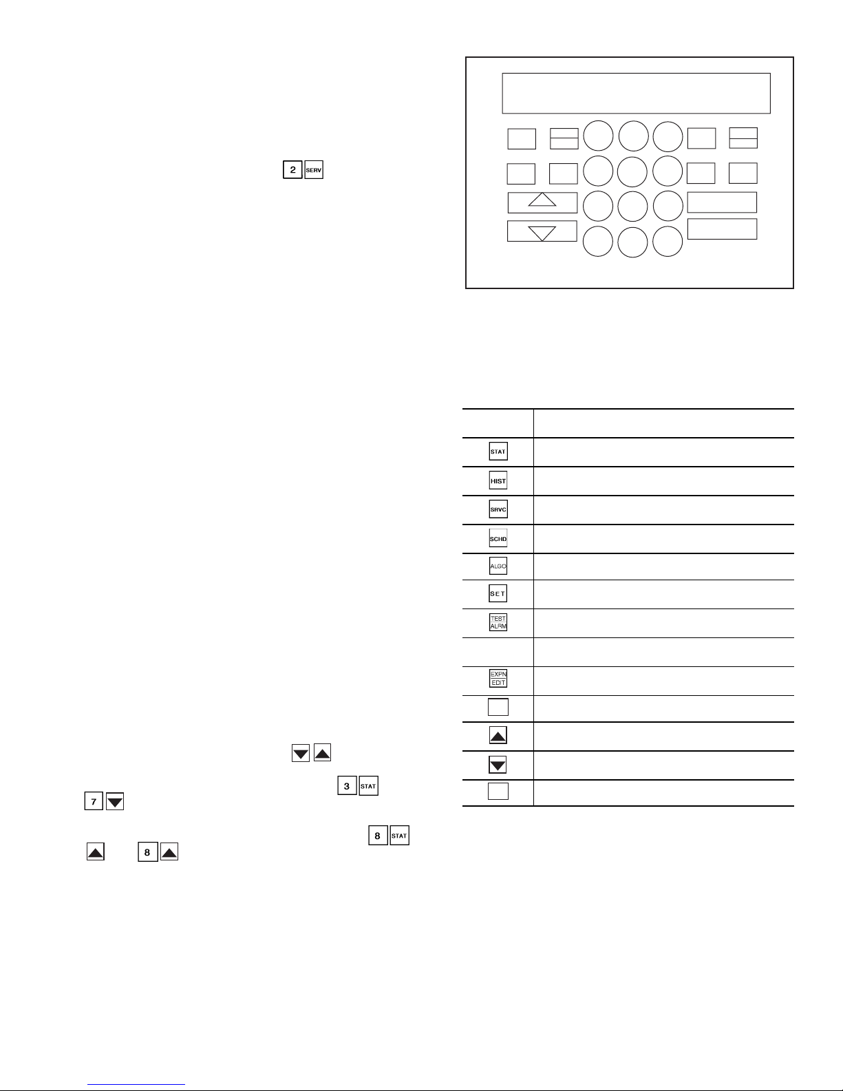
Keypad and Display Module (Also Called
HSIO-II) —
cate with the processor. It is used to enter configurations and
set points and to read data, perform tests, and set schedules.
The device consists of a keypad with 7 function keys, 5 operative keys, 12 numeric keys (0 to 9, •, and -), and a 2-line,
24-character alphanumeric liquid crystal display . See Fig. 7.
ACCESSING FUNCTIONS AND SUBFUNCTIONS —
Table 10 shows a brief description of the keypad buttons.
Table 11A shows the 6 functions (identified by name) and the
subfunctions (identified by number). Table 11B shows the
6 functions (identified by name) and the subfunctions (identified by number) when using the optional remote enhanced display controller. Table 12 shows a brief example on how to
access subfunctions.
NOTE: It is not necessary to use the through every
item in a subfunction. For example, if you wanted to read the
oil pressure for the A1 compressor, press , then
procedure to view an item near the bottom of a subfunction. To
view Condenser Pump Flow Switch status, press ,
, and . This procedure is available in all functions
except the TEST function.
AUTOMATIC DEF AULT DISPLAY — When the keypad has
not been used for 10 minutes, the display automatically
switches to the rota tin g a uto ma ti c defa u lt d isp la y. This display
contains the 5 parts shown below .
Entering Fluid T emp
Leaving Fluid T emp
Percent Total Capacity
This module allows the operator to communi-
press to go directly to A1 Oil Pre ssure. Use a similar
xx.x° F
xx.x° F
xxx.x%
Table 10 — Keypad and Display Module Usage
FUNCTION
KEYS
OPERATIVE
KEYS
CLEAR
ENTER
STATUS — For displaying diagnostic codes and
current operating information about the machine.
HISTORY — For displaying run time, cycles, and
previous alarms.
SERVICE — For entering specific unit configur ation
information and enabling manual control function.
SCHEDULE — For entering occupied/unoccupied
schedules for unit operation.
ALGORITHM — Not used.
SET POINT — For entering operating set points
and daytime information.
TEST — For testing operating of the analog and
discrete outputs.
EXPAND — For displaying a non-abbreviated
expansion of the display.
CLEAR — For clearing the screen of all displays.
UP ARROW — For returning to previous display
position.
DOWN ARROW — For advancing to next display
position.
ENTER — For entering data.
USE
USE
T ota l Num ber of A larm s
xx
MODES : MODE_TBL
Current active modes
All functions are made up of a group of subfunctions. To enter a subfunction, first press the subfunction number desired.
Then press the function key in which the subfunction resides.
To move within that subfunction, press the up or down arrow
keys. Another subfunction may be entered at any time by
pressing the subfunction number, then the function key. Depending on system type and configuration, all displays may not
be shown.
15
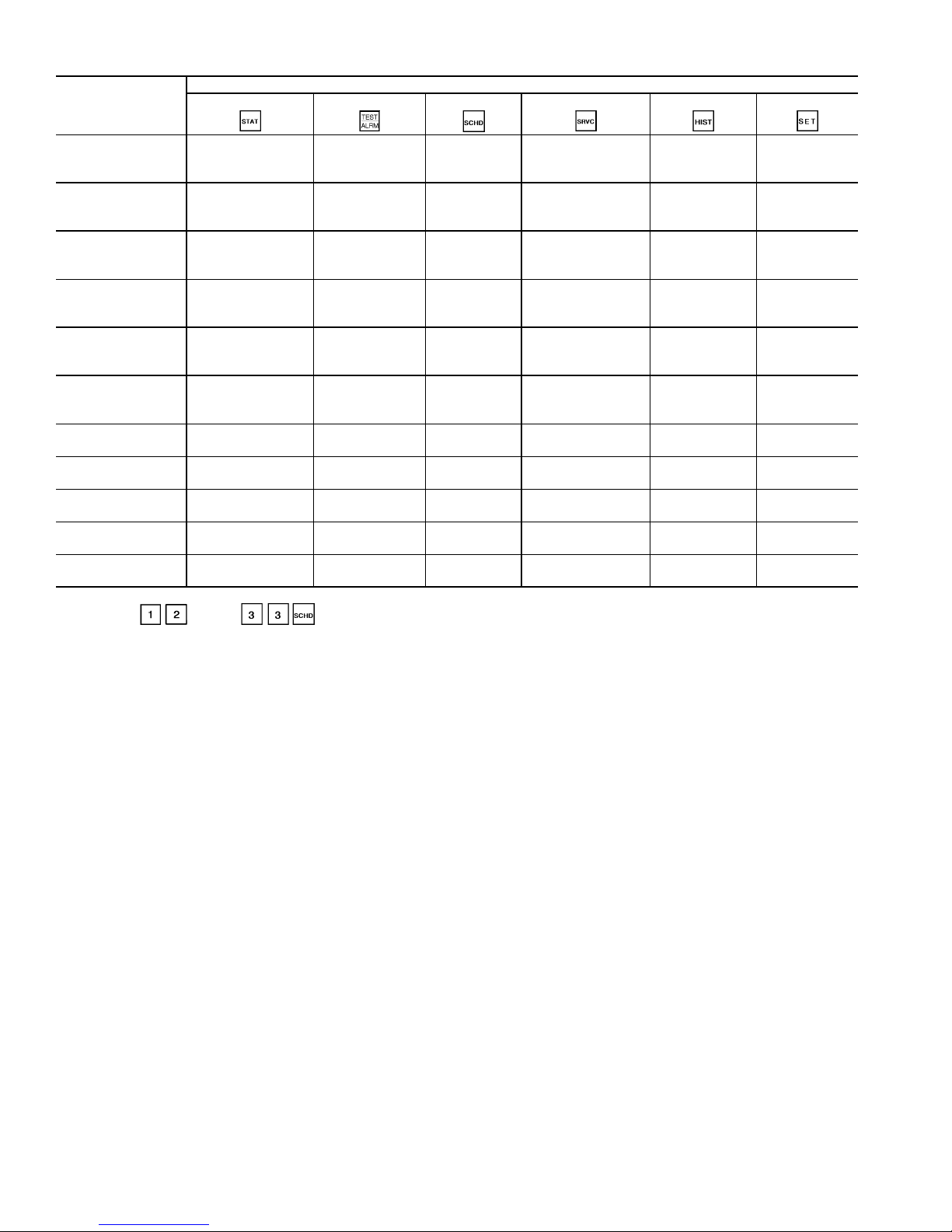
SUBFUNCTION NO.
Table 11A — HSIO Functions and Subfunctions
FUNCTIONS
Status Test Schedule Service History Set Point
1
2
3
4
5
6
7
8
9
10
11
Alarm Display Circuit A
General Pa r ameters Circuit B
Circuit A
Analog Values
Circuit A
Discrete Inputs/
Outputs Table
Circuit B
Analog Values
Circuit B
Discrete Inputs/
Outputs Table
Unit Analog
Parameters
Miscellaneous
Inputs/Outputs
Operating Modes — Holiday 06
Capacity Control — Holiday 07
Dual Chiller — Holiday 08
®
Ice Build
Occupancy
Schedule
Local/Normal
Occupancy
Schedule
Remote CCN
Occupancy
Schedule
Holiday 01
Configuration
Configuration
Configuration
Configuration
Configuration
Configuration
Configuration
Configuration*
Discrete Outputs
Discrete Outputs
Unit
Discrete Outputs
Valves and
Motormaster
Control
—Holiday 02
—Holiday 03
—Holiday 04
—Holiday 05
Factory
Configuration
Options
Configuration1
Options
Configuration 2
Reset/Demand Limit
Configuration
Machine
Configuration
Codes
———
Transducer
Calibration
Manual Control — —
Master /Slave
Configuration
———
———
Operating Hours Set Point s
Alarm History English/Metric
— Bus Address
— Time/Date
Configuration
— CCN
Enable/Disable
——
——
*Subfunctions through are for configuring Holidays 09 through 30.
16
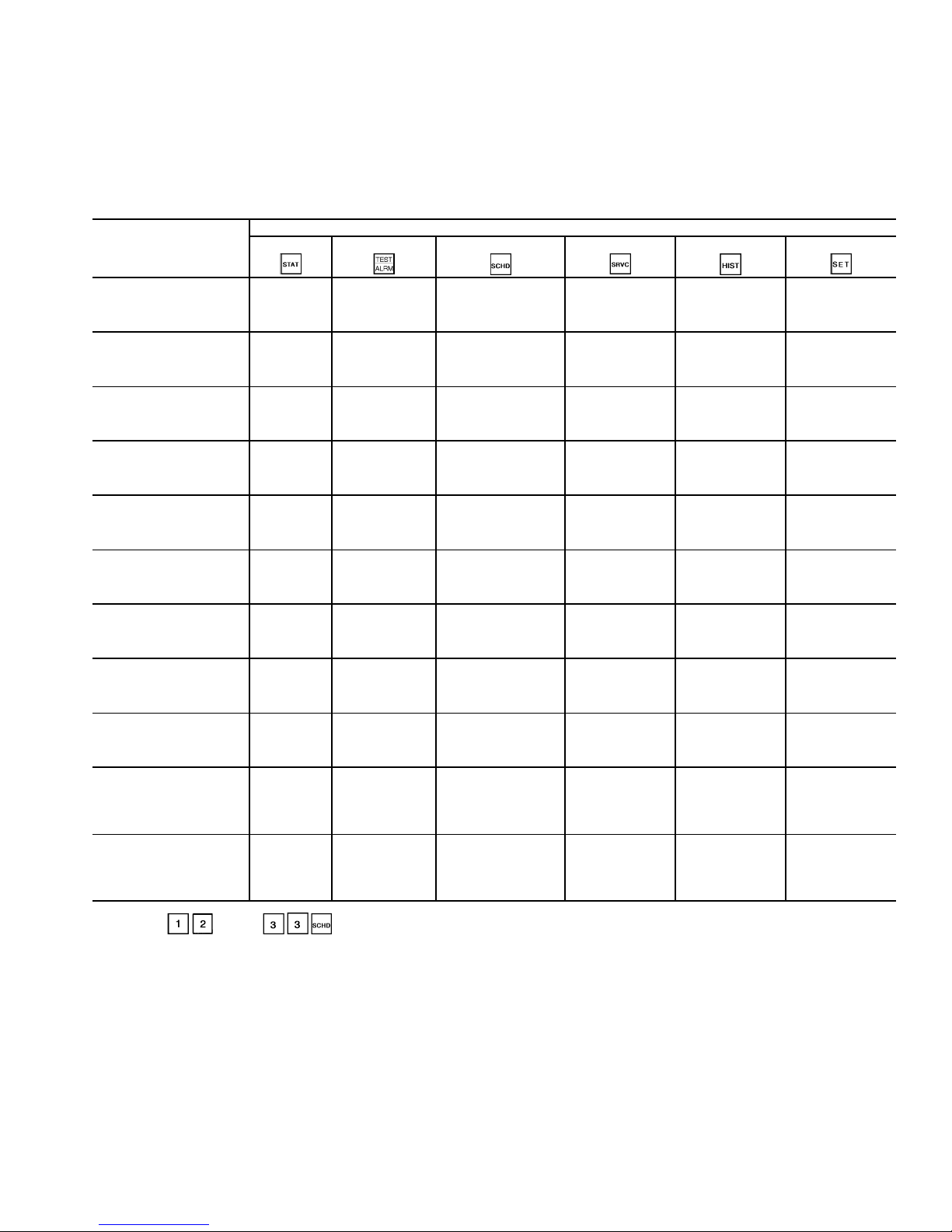
Table 11B — Functions and Subfunctions Cross-Reference for the
Optional Remote Enhanced Display Controller
The optional Remote Enhanced Display controller cross
reference table below can be used as a guide to access the same
information outlined in the HSIO functions and subfunctions
table (see Table 11A). For example, in Table 11A, the alarm
history is accessed through the HSIO by pressing 2 and the
History button on the keypad (see Table 10). The Remote Enhanced Display cross reference table lists the menu item from
the Remote Enhanced Display which contains the alarm history information. In another example, from Table 11A, pressing 3
and the Status button on the HSIO keypad will access the circuit A analog values. In the table below, the circuit A analog
values are accessed by selecting STATUS CIRCA_AN from
the appropriate Remote Enhanced Display menu.
HSIO SUBFUNCTION
NO.
1
2
3
4
5
6
7
8
9
10
11
HSIO FUNCTION KEY
Status Test Schedule Service History Set Point
STATUS
A_UNIT_1
STATUS
A_UNIT_1
STATUS
CIRCA_AN
STATUS
CIRA_DIO
STATUS
CIRCB_AN
STATUS
CIRB_DIO
STATUS
UNIT_2
STATUS
UNIT_3
STATUS
MODE_TBL
SERVICE
CONTROL
ALGORITHM
STATUS
LOADFACT
SERVICE
CONTROL
ALGORITHM
STATUS
LEADLAG
SERVICE
CONTROL TEST
SERVI C E
CONTROL TEST
SERVI C E
CONTROL TEST
SERVI C E
CONTROL TEST
—
—
—
—
—
—
—
SCHEDULE
OCCPC01S
SCHEDULE
OCCPC02S
SCHEDULE
OCCPC65S
SERVICE
EQUIPMENT
CONFIGURATION
HOLIDAY,HOLDY_01
SERVICE
EQUIPMENT
CONFIGURATION
HOLIDAY,HOLDY_02
SERVICE
EQUIPMENT
CONFIGURATION
HOLIDAY,HOLDY_03
SERVICE
EQUIPMENT
CONFIGURATION
HOLIDAY,HOLDY_04
SERVICE
EQUIPMENT
CONFIGURATION
HOLIDAY,HOLDY_05
SERVICE
EQUIPMENT
CONFIGURATION
HOLIDAY,HOLDY_06
SERVICE
EQUIPMENT
CONFIGURATION
HOLIDAY,HOLDY_07
SERVICE
EQUIPMENT
CONFIGURATION
HOLIDAY,HOLDY_08*
SERVICE
EQUIPMENT
CONFIGURATION
SERVICE
EQUIPMENT
CONFIGURATION
OPTIONS1
SERVICE
EQUIPMENT
CONFIGURATION
OPTIONS2
SERVICE
EQUIPMENT
CONFIGURATION
RESETCON
SERVICE
EQUIPMENT
CONFIGURATION
CONCODES
SERVICE
EQUIPMENT
CONFIGURATION
EXV TESTS
SERVICE
EQUIPMENT
SERVICE
CALIBRTE
SERVICE
EQUIPMENT
SERVICE
MAN_CTRL
SERVICE
EQUIPMENT
CONFIGURATION
MSTR_SL V
———
———
SERVIC E
EQUIPMENT
CONFIGURATION
STRTHOUR
SERVIC E
ALARM
HISTORY
—
—
—
——
——
——
——
SETPOINT
SERVICE
LID
CONFIGURATION
SERVICE
CONTROLLER
IDENTIFICATION
SERVICE
EQUIPMENT
SERVICE
TIME AND DATE
STATUS
A_UNIT_1
*Subfunctions through are for configuring Holidays 09 through 30
NOTE: The optional Remote Enhanced Display controller uses the same password (1111) as the HSIO.
, and are also found under Service, Equipment Configuration.
17
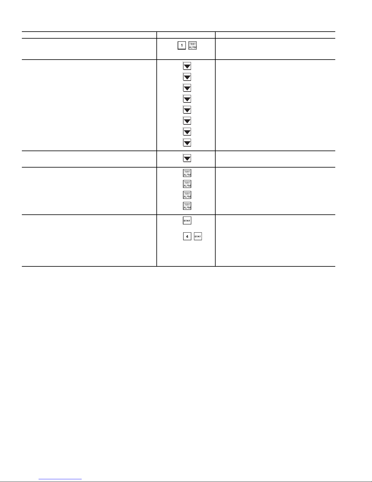
Table 12 — Accessing Functions and Subfunctions
OPERATION KEYPAD ENTRY DISPLAY RESPONSE
To access a function, press
subfunction no. and function
name key. Display shows subfunction group.
To move to other elements,
scroll up or down using arrow keys.
When the last element in a
subfunction has been displayed,
the first element is repeated.
To move to next subfunction
it is not necessary to use
subfunction number. Press
function name key to
advance display through all
subfunctions within a
function and then back
to the first.
Circuit A Discrete Outputs
Loader A1
Relay is OFF
Loader A2
Relay is OFF
Minimum Load Valve A
Relay is OFF
Circuit A Oil Heater
Relay is OFF
A1 Mtr. Cooling Solenoid
Relay is OFF
A2 Mtr. Cooling Solenoid
Relay is OFF
Circuit A Oil Pump
Relay is OFF
Oil Solenoid A1
Relay is OFF
Oil Solenoid A2
Relay is OFF
Loader A1
Relay is OFF
Circuit B Discrete Outputs
Unit Discrete Outputs
Valves and Motor Master
Circuit A Discrete Outputs
To move to another function,
either depress function name
key for desired function
(display shows the first
subfunction),
or
Access a specific subfunction by using the subfunction number and the
function name key.
Alarms : xx
Reset Alarms : 1 <ENTER>
CIR. A DISCRETE OUTPUTS
18
ST ATUS FUNCTION — This function shows the rotating display, current status of alarm and alert (diagnostic) codes,
capacity stages, operating modes, chilled water set point, all
measured system temperatures and pressures, analog inputs,
and switch inputs. Refer to Table 13 for a complete description
of the function.
Alarms/Alerts
— Alarms and alerts are mess ages that one or
more faults have been detected. The alarms and alerts indicat e
failures that cause the unit to shut down, terminate an option
(such as reset) or result in the use of a default value such as
a set point. Refer to the Troubleshooting section for more
information.
Up to 10 alarms/alerts can be stored at once. To view them,
press . The control will display the current total number of alarms/alerts. Use the arrow keys to scroll through the
list. Press the key when needed to view the full description
of an alarm or alert. Press to clear all the alarms. Se e
ENTER
T able 14.
IMPORTANT: Do not clear the alarms without first
reviewing the full list and investigating and correcting
the cause of t he a lar ms .
When an alarm or alert is s tored in the display and the machine automatically resets, the al arm/alert is deleted. Codes for
safeties which do not automatically reset are not deleted until
the problem is corrected and the machine is reset. To clear
manual reset alarms from the CPM modules, the reset button
on the HSIO bracket must be pressed. Next, switch the LOR
switch to OFF and back to Local or Remote position (default
alarm clearing method). Press and then to
ENTER
clear the alarm from the PSIO if the default LOR reset function
has been disabled.
General Parameters
— General operating parameters are displayed including control mode, run status, CCN status, and the
5 most current alarms. Press to display these and the
other values as shown in T able 13.
Circuit A and B Analog and Discrete Information
— Circuit A Analog Values can be vie wed by pre ssing and
scrolling down to see current system operating conditions such
as pressures and temperatures. Pressing will bring up
Circuit A Discrete Inputs and Outputs. Scroll down to view the
On/Off status of the compressor(s), loaders, solenoids, and
pumps. Oil switch and feedback inputs are also displayed.
Press and to view the identical ana log values and discrete inputs and outputs for Circuit B. See Table 13
for a complete display.
Unit Analog Parameters and Temperature Reset
— Press
and scroll down to display the unit entering and leaving fluid temperatures as well as the temperature reset signal
and calculated values.
Miscellaneous Inputs and Outputs
— Pressing and
scrolling down will reveal the On/Off status of the condenser
fans (30GX only). Also found here are the Demand Limit settings, pump relay and switch status, and miscellaneous items
such as Heat/Cool and Dual Set Point switch positions. See Table 13 for a complete list.
— The operating modes are displayed to indicate the
Modes
operating status of the unit at a given time. See Table 15 for a
complete list of all mode s.
To enter the MODES subfunction, press and use
the key to view all current modes of operation. See
Table 16.
Capacity Control
— Pressing , this subfunction
displays the load/unload factor, control point, and leaving water temperature. Scrolling down will also reveal the liquid level
sensor values in degrees format.
Dual Chiller
— Pressing will access the dual
chiller control status. This subfunction will display whether or
not the chiller is operating as a Master or Slave, any alarm conditions present for dual chiller control, and lead/lag information
for changeover. Dual chiller control is configured under
.
19
Table 13 — Status Function and Subfunction Directory
SUBFUNCTION KEYPAD ENTRY DISPLAY COMMENT
1 Alarms
Alarms : xx
Reset Alarms : 1 <ENTER>
All current alarms are displayed
Use as needed
2 General Parameters
3 Circuit A Analog Values
See Legend on page 25.
GENERAL PARAMETERS
Control Mode
Run Status
Off/On
Occupied ?
Yes/ No
CCN Enable
Off/On
CCN Chiller Start/Stop
Start/Stop
Alarm State
Normal/Alarm
Current Alarm 1
x.xx
Current Alarm 2
x.xx
Current Alarm 3
x.xx
Current Alarm 4
x.xx
Current Alarm 5
x.xx
Active Demand Limit
xxx.x%
Percent Total Capacity
xxx.x%
Water/Brine Setpoint
xx.x dF
Control Point
xx.x dF
Entering Fluid Temperature
xx.x dF
Leaving Fluid Temperature
xx.x dF
Emergency Stop
Emstop
Minutes Left for Start
xx min
Heat-Cool Status
Heat/Cool
CIRCUIT A ANALOG VALUES
Total Capacity
xxx.x%
Available Capacity
xxx.x%
Discharge Pressure
xxx.x PSI
Suction Pressure
xxx.x PSI
A1 Oil Pressure Diff.
xxx.x PSI
A2 Oil Pressure Diff.
xxx.x PSI
A1 Oil Pressure
xxx.x PSI
A2 Oil Pressure
xxx.x PSI
Discharge Gas Temperature
xxx.x dF
A1 Motor Temperature
xxx.x dF
A2 Motor Temperature
xxx.x dF
Displays LOCAL ON/OFF or
CCN ON/OFF
Force/clear value with HSIO or CCN device.
Must be ON for CCN clock control.
Percentage of total circuit capacity
currently in use.
Percentage of Total Capacity value not in an alarm or fault condition.
20
Table 13 — Status Function and Subfunction Directory (cont)
3 Circuit A Analog Values (cont) SAT Condensing Temp
4 Circuit A Discrete Inputs/Outputs
5 Circuit B Analog Values
SUBFUNCTION KEYPAD ENTR Y DISPLAY COMMENT
xxx.x dF
Saturated Suction Temp
xxx.x dF
EXV Percent Open
xxx.x%
Motormaster Speed
xxx.x%
Water Valve Position
xxx.x%
Cooler Level Indicator
x.xx
CPM A1 Feedback
x.x Volts
CPM A2 Feedback
x.x Volts
Circuit A Econ Pressure
xxx.x PSI
CIR. A DISCRETE OUTPUTS
Compressor A1
Off/On
Compressor A2
Off/On
Loader A1
Off/On
Loader A2
Off/On
Minimum Load Valve A
Off/On
Circuit A Oil Heater
Off/On
A1 Mtr Cooling Solenoid
Off/On
A2 Mtr Cooling Solenoid
Off/On
Circuit A Oil Pump
Off/On
Oil Solenoid A1
Off/On
Oil Solenoid A2
Off/On
CIR. A DISCRETE INPUTS
Circuit A Oil Switch
Open/Close
Compressor A1 Feedback
Off/On
Compressor A2 Feedback
Off/On
CIRCUIT A ANALOG VALUES
Total Capacity
xxx.x%
Available Capacity
xxx.x%
Discharge Pressure
xxx.x PSI
Suction Pressure
xxx.x PSI
B1 Oil Pressure Diff.
xxx.x PSI
B2 Oil Pressure Diff.
xxx.x PSI
B1 Oil Pressure
xxx.x PSI
B2 Oil Pressure
xxx.x PSI
Discharge Gas Temperature
xxx.x dF
See Table 5.
See Table 5.
Percentage of total circuit capacity
currently in use.
Percentage of To tal Capacity value not in an
alarm or fa ult condition.
21
5 Circuit B Analog Values (cont)
SUBFUNCTION KEYPAD ENTR Y DISPLAY COMMENT
6 Circuit B Discrete Inputs/Outputs
7 Unit Analog Parameters
Table 13 — Status Function and Subfunction Directory (cont)
B1 Motor Temperature
xxx.x dF
B2 Motor Temperature
xxx.x dF
SAT Condensing Temp
xxx.x dF
Saturated Suction Temp
xxx.x dF
EXV Percent Open
xxx.x%
Motormaster Speed
xxx.x%
Water Valve Position
xxx.x%
Cooler Level Indicator
x.xx
CPM B1 Feedback
x.x Volts
CPM B2 Feedback
x.x Volts
Circuit B Econ Pressure
xxx.x PSI
CIR. B DISCRETE OUTPUTS
Compressor B1
Off/On
Compressor B2
Off/On
Loader B1
Off/On
Loader B2
Off/On
Minimum Load Valve B
Off/On
Circuit B Oil Heater
Off/On
B1 Mtr Cooling Solenoid
Off/On
B2 Mtr Cooling Solenoid
Off/On
Circuit B Oil Pump
Off/On
Oil Solenoid B1
Off/On
Oil Solenoid B2
Off/On
CIR. B DISCRETE INPUTS
Circuit B Oil Switch
Open/Close
Compressor B1 Feedback
Off/On
Compressor B2 Feedback
Off/On
UNITS ANALOG PARAMETERS
Cooling Entering Fluid
xx.x dF
Cooling Leaving Fluid
xx.x dF
Condenser Entering Fluid
xx.x dF
Condenser Leaving Fluid
xx.x dF
Reclaim Entering Fluid
xx.x dF
Reclaim Leaving Fluid
xx.x dF
5 Volt Supply
x.x Volts
See Table 5.
See Table 5.
See Legend on page 25.
22
7 Unit Analog Parameters (cont)
SUBFUNCTION KEYPAD ENTR Y DISPLAY COMMENT
8 Misc. Inputs/Outputs
9 Operating Modes
Table 13 — Status Function and Subfunction Directory (cont)
TEMPERATURE RESET
4-20 mA Reset Signal
xx.x mA
Return Reset Signal
xx.x dF
External Reset Signa l
xx.x dF
Outdoor Air Temp
xx.x dF
Calculated Reset
xx.x dF
MISC INPUTS/OUTPUTS
FAN_1
Off/On
FAN_2
Off/On
FAN_3
Off/On
FAN_4
Off/On
FAN_5
Off/On
FAN_6
Off/On
DEMAND LIMIT
4-20 mA Demand Signal
x.xx mA
Demand Switch 1
Off/On
Demand Switch 2
Off/On
CCN Loadshed Signal
Normal/Alarm
Max Allowable CAP
xxx.x%
PUMPS
Cooler Pump Relay
Off/On
Cooler Pump Flow Switch
Off/On
Condenser Pump Relay
Off/On
Condenser Pump Flow Switch
Off/On
MISCELLANEOUS
Ice Valve
Off/On
Ice Build Complete
Yes/N o
Heat/Cool Switch
Heat/Cool
Dual Set point Switch
Off/On
Cooler Heater
Off/On
Options Temperature 1
xx.x dF
Options Temperature 2
xx.x dF
MODES :MODE_TBL
mode name ON/OFF
LOCAL OFF
CCN OFF
Not Used
Not Used
Only active modes displayed
Scroll with down arrow key to display
23
9 Operating Modes (cont)
SUBFUNCTION KEYPAD ENTR Y DISPLAY COMMENT
Table 13 — Status Function and Subfunction Directory (cont)
CLOCK OFF
LOCAL ON
CCN ON
CLOCK ON
DUAL SP ACTIVE (1st SP)
DUAL SP ACTIVE (2nd SP)
TEMPERATURE RESET
ACTIVE
DEMAND LIMIT ACTIVE
LOAD LIMIT ACTIVE
LOW SOURCE TEMP PROTECT
RAMP LOADING ACTIVE
TIMED OVERRIDE ACTIVE
LOW COOLER SUCTION TEMP
WSM CONTROLLING
SLOW CHANGE OVERRIDE
OFF TO ON DELA Y ACTIVE
FSM CONTROLLING
2 CHILLR LEAD LAG ACTIVE
2 CHILLR LL COMM FAILURE
CIR A LOW DISCHG SUPERHT
CIR B LOW DISCHG SUPERHT
CIR A HIGH SDT
CIR B HIGH SDT
10 Capacity Control
See Legend on page 25.
CAPACITY CONTROL
Load/Unload Factor
xxx.x%
Control Point
xx.x dF
Leaving Water Temp
xx.x dF
MISC. INDICATORS
Liquid Lvl Sensor Cir. A
xx.x dF
Liquid Lvl Sensor Cir. B
xx.x dF
24
11 Dual Chiller
Table 13 — Status Function and Subfunction Directory (cont)
SUBFUNCTION KEYPAD ENTR Y DISPLAY COMMENT
DUAL CHILLER
Unit Master/Slave
0 / 1 / 2
Master / Slave Ctrl Active
Yes / N o
Lead Chiller
1 / 2
0 = Neither
1 = Master
2 = Slave
1 = Master
2 = Slave
0 = Chiller OFF
1 = Valid Run State in CCN Mode
3 = Chiller in Local Mode
5 = Shutdown on Alarm
6 = Communications Failure
Yes if Lead / Lag Balance Enabled
1 = Master / S lave Have Same Address
2 = Master / Slave Communication Failure
3 = Chiller in Local Mode
4 = Slave Shutdown on Alarm(s)
5 = Master Configured for Heating
6 = No Slave Configured
CCN — Carrier Comfort Network
CPM — Compressor Protection Module
dF — Degrees Fahrenheit
EXV — Electronic Expansion Valve
FSM — Flotronic™ System Manager
LL — Lead/Lag
MTA — Must Trip Amps
SAT — Saturated
SDT — Saturated Discharge Temperature
SP —Set Point
WSM — Water System Manager
LEGEND
Slave Chiller State
0 / 1 / 3 / 5 / 6
Slave Chiller Total Cap
xxx.x%
Lead / Lag Changeover
Master / Slave Error
1 / 2 / 3 / 4 / 5 / 6
Table 14 — Reading and Clearing Alarms
KEYPAD ENTRY DISPLAY COMMENT
ENTER
Alarm: 02
Reset Alarms: 1 <ENTER>
Comp A1 F ail - 1.80 Curr
Alarm: 15:12 04/15/96
Comp A1 Fail - 1. 80 Cur rent Phase Reversal
Alarm: 15:12 04/15/96
Compressor A1 Low Oil Pr
Alarm: 10:34 04/15/96
Compressor A1 Low Oil Pressure
Alarm: 10:34 04/15/96
Alarm: 02
Reset Alarms: 1 <ENTER>
Alarm: 00
Reset Alarms: 1 <ENTER>
Entering Fluid Temp
xx.x dF
Leaving Fluid Temp
xx.x dF
Percent Total Capacity
xxx.x%
Total Number of Alarms
xx
MODES: MODE_TBL
List of All Curren t Modes
Press CPM Reset
button first
Alarms reset
and cleared
Returns to rotating
default display
25
Table 15 — Operational and Mode Display Codes
CODE DESCRIPTION
LOCAL OFF Unit is off. LOCAL/OFF/REMOTE switch is in OFF
CCN OFF Unit is off. LOCAL/OFF/REMOTE switch is in
CLOCK OFF Unit is off due to internal clock schedule. LOR
LOCAL ON Unit is on. LOR switch is in LOCAL position and
CCN ON Unit is on due to CCN command. LOR switch is in
CLOCK ON Unit is on due to internal clock schedule or occu-
DUAL SP ACTI VE
(1st SP)
DUAL SP ACTI VE
(2nd SP)
TEMPERATURE
RESET ACTIVE
DEMAND LIMIT
ACTIVE
FSM
CONTROLLING
RAMP LOADING
ACTIVE
TIMED OVERRIDE
ACTIVE
WSM
CONTROLLING
SLOW CHANGE
OVERRIDE
position or LOCAL/OFF/REMOTE switch is in
REMOTE position and remote contacts are open.
LOCAL position and CCN control is enabled (Stop
state) or CCN is enabled (Stop state) with LOR
switch in REMOTE position and remote contacts
closed.
switch is in LOCAL position.
CCN is disabled or LOR switch is in REMOTE
position with contacts closed and CCN is disabled.
LOCAL position and CCN is enabled (Run state)
or LOR switch is in REMOTE position with contacts closed and CCN is enabled (Run state).
pied override function. LOR switch is in LOCAL
position.
Dual set point is in effect. In this mode, unit continues to run in an occupied condition, and leaving
fluid set point is automatically controlled to the
CSP1 set point in the SET POINT function.
Dual set point is in effect. In this mode, unit continues to run in unoccupied condition, but leaving
fluid set point is automatically increased to a
higher level (CSP2 set point is in SET POINT
function).
Temperature reset is in effect. In this mode, unit is
using temperature reset to adjust leaving fluid set
point upward, and unit is currently controlling to
the modified set point. The set point can be modified based on re turn flu id, outdoor -air temp erat ure,
space temperature, or 4 to 20 mA signal.*
Demand limit is in effect. This indicates that
capacity of unit is being limited by demand limit
control option. Because of this limitation, the unit
may not be able to produce the desired leaving
fluid temperature. Demand limit can be controlled
by a switch or 4 to 20 mA signal.*
Flotronic™ System Manager (FSM) is controlling
the chiller.
Ramp load (pulldown) limiting is in effect. In this
mode, the rate at which leaving fluid temperature
is dropped is limited to a predetermined value to
prevent compressor overloading. See CRAMP set
point in the SET POINT function (page 27). The
pulldown limit can be modified, if desired, to any
rate from 0.2° F to 2° F (0.1° to 1° C)/minute.
Timed override is in effect. This is a 1 to 4 hour
temporary override of the programmed sche dul e,
forcing unit to occupied mode. Override can be
implemented with unit und er LOCA L/ R EMOTE or
CCN control. Override expires after each use.
Water System Manager is controlling the chiller.
Slow change override is in effect. The leaving fluid
temperature is close to and moving towards the
control point.
CODE DESCRIPTION
OFF TO ON
DELA Y ACTIVE
LOAD LIMIT
ACTIVE
2 CHILLR LEAD
LAG ACTIVE
2 CHILLR LL
COMM FAILURE
CIRCUIT A LOW
DISCHARGE
SUPERHT
CIRCUIT B LOW
DISCHARGE
SUPERHT
CIRCUIT A
HIGH SCT
CIRCUIT B
HIGH SCT
LOW COOLER
SUCTION
TEMPERATURE
Chiller is being held off by Minutes Off Time found by
keying . Also, normal operation of the chiller
includes a minimum 1.5 minute delay after a capacity
stage change has been made. This delay is adjustable
from 1.5 to 6 minutes.
This function determines the maximum allowable
capacity that can be running and is accomplished
through the Flotronic System Manager. The unit may
not be able to produce the desired leaving fluid
temperature.
This mode indicates that Master and Slave chillers
have been configured and are operating using the
Dual Chiller control. This is a series water flow
arrangement where chilled fluid is piped to the Slave
Chiller first and then through the Master Chiller.
Leaving Fluid Temperature control is performed based
on Master Chiller Leaving Fluid Temperature.
This mode indicates that communication has been lost
between the Master and Slave chillers. Both
chillers will return to a stand-alone mode of operation
until communication is restored.
If the discharge superheat is less than 5° F (2.8° C)
and falling, a circuit loader will be deenergized every
30 seconds. The final stage will not be unloaded
unless an alarm condition is present.
See description for Circuit A above.
If the circuit is running and the Saturated Condensing
Temperature (SCT) is greater than the Maximum
Condensing Temperature Set point (MCT_SP) minus
12° F (6.7° C), the control will not add any stages.
If the SCT is greater than the MCT_SP plus 5° F
(2.8° C), the circuit will be unloaded and shut down if
necessary. If the SCT is greater than the MCT_SP
plus 2° F (1.1° C) for one minute, a loader will be
deenergized.
If the SCT is greater than the MCT_SP minus 4° F
(2.2° C), the control will compare the maximum
operatin g pressure set point (MOP_SP) with the modified MOP_SP (MOP_CTRL).
If the MOP_CTRL is greater than the MOP_SP, the
mode will be cleared. Otherwise the control will
display the high SCT override mode. The capacity
control routine will not add any stages. If the circuit is
at its lowest capacity, this mode will be ignored.
See description for Circuit A above.
Circuit A and/or B low saturated suction condition
exists. Control will not increase capacity on affected
circuits. The EXV of the affected circuit(s) will be
opened until the condition does not exist.
CCN — Carrier Control Network
CSP — Cooling Set Point
CRAMP — Cooling Ramp Loading
EXV — Electronic Expansion Valve
LOR — Local/Off/Remote
SP —Set Point
WSM — Water System Manager
*A field-supplied 500 Ohm 1/
the input terminals when using a 4 to 20 mA signal.
LEGEND
W resistor must be installed across
2
Table 16 — Reading Current Operating Mode
KEYP AD ENTR Y DISPL AY
MODES :MODE_TBL
CCN ON
DEMAND LIMIT
ACTIVE
26
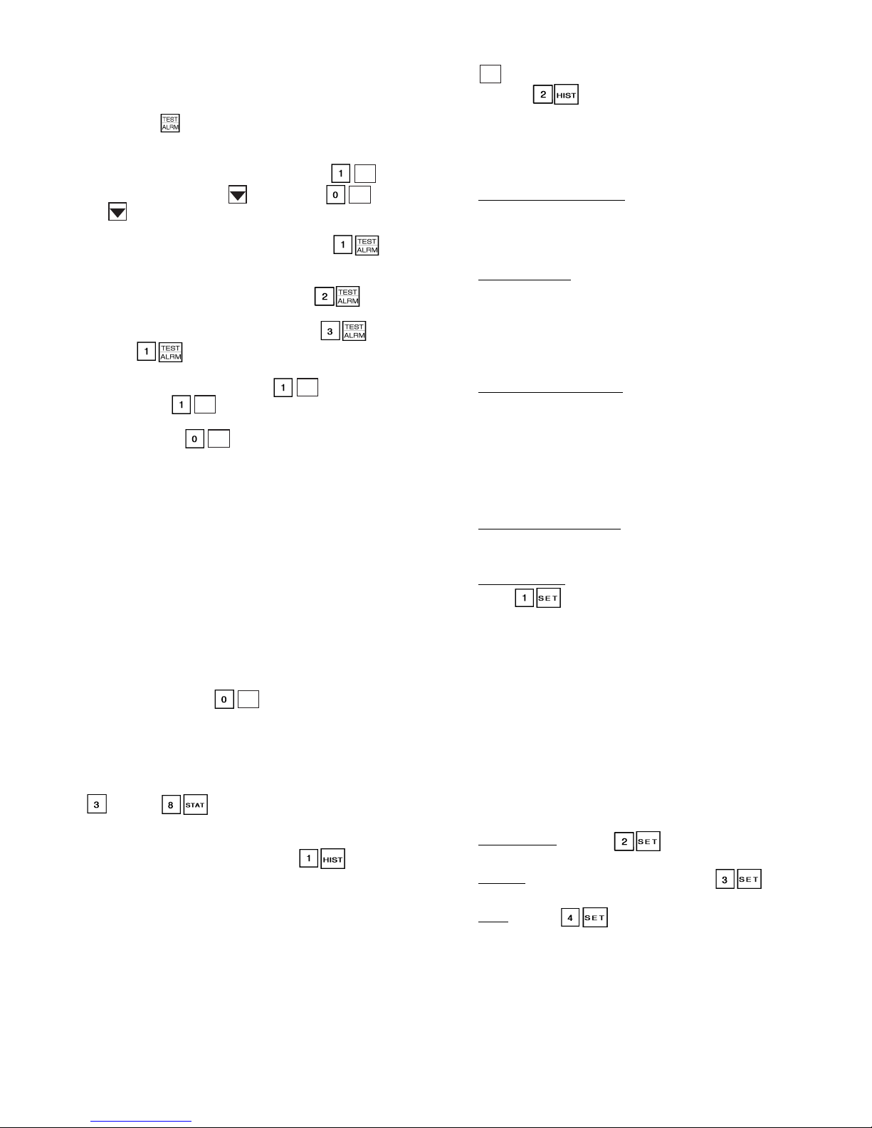
TEST FUNCTION — The test function operates the diagnos-
ENTER
tic program. To initiate the test function, the LOCAL/OFF/
REMOTE switch must be in the OFF position.
To reach a particular test, press its subfunction number followed by the key then scroll to the desired test by pressing
the down arrow key. Refer to Ta ble 17 for a complete description of the test function.
To start a test of discrete outputs, press . To end
the test, simply press the key or press . Pressing
ENTER
ENTER
the key after a test has started advances the system to the
next test, whether the current test is operating or has timed out.
Circuit A discrete outputs can be tested in and include loaders, minimum load valve, oil heater (if equipped),
motor cooling solenoids, oil pump, and oil solenoi ds. Similarly,
Circuit B discrete outputs can be tested in . Additional
discrete outputs, including condenser fans, cooler heater, water
pumps, and remote alarms can be tested in .
®
Press to access Valves and Motormaster
control
analog outputs. Scroll down to display Circuit A EXV Valve
with a target percent of 0%. Press to step the EXV to
25%. Pressing three additional times will move the
ENTER
ENTER
EXV to 50%, 75%, and 100% The EXV may be closed in 25%
steps by pressing for each desired step. Wait 30 sec-
ENTER
onds between each step when opening and closing for the valve
to stop moving. Pressing the down arrow will display Circuit B
EXV Valve and it is tested in the same manner as Circuit A.
Also available for test are Circuit A water valve (if equipped)
and the Circuit A and B Fan speed % (direct control Motormaster device) outputs for 30GX chillers. These are tested in
the same manner as the EXV valves. Note that condenser fan
motors are NOT started during fan speed quick tests. Measure
4 to 20 mA dc output using meter in series with violet wire to
controller. See pages 74 and 75 of Field W iring section.
While the unit is in test, you can leave the test function and
access another display or function by pressing the appropriate
keys. However, a component that is operating when another
function is accessed remains operating. You must re-enter the
test function and press to shut down the component.
ENTER
Components with a timed operating limit time out normally
even if another function is accessed.
Since the Test function checks only certain outputs, it is a
good practice to also check all inputs and outputs accessible
through the Status function. These can be located by pressing
through . If keypad is not used for 10 minutes,
the unit automa tically l eave s the tes t functi on and res umes t he
normal rotating display . See Table 18.
HISTORY FUNCTION — Pressing displays total
machine operating hours. Scroll down to display machine run
time and starts, and total run time and starts for each compressor. Refer to Table 19 for a complete description of the function. When the PSIO-1 module is replaced or downloaded with
Version 4.0 or later software, the number of starts and run
hours may be changed one time. Record the current values
from the PSIO before removing the module or downloading
new software. The number of starts and hours may be changed
by entering the desired value at the HSIO and pressing the
key.
Pressing displays the last 10 alarms along with a
description and time and date of occurrence of each alarm.
SET POINT FUNCTION — Set points are entered through
the keypad. Set points can be changed within the upper and
lower limits, which are fixed. The ranges are listed below.
Refer to Tabl e 20 for a complete description of the function.
Cooling Set Point 1 and 2
Water:
38 to 70 F
(3.3 to 21.1 C)
Medium
T emp erature Brine:
14 to 70 F
(–10 to 21.1 C)
Temperature Brine:
Low
–13 to 70 F
(–25 to 21.1 C)
Reset Set Points
Maximum
Reset Range:
–30 to 30 F
(–17 to 17 C)
External Signal Reset: 4 to 20 mA (2 to 10 vdc with
External
T emp erature Reset:
–40 to 240 F
(–40 to 118 C)
500 Ohm
1
/2 watt resistor)
Chiller Fluid ∆:
0° to 15 F
(0° to 8 C)
Demand Limit Set Points
Switch Input: Step 1 — 0 to 100% Capacity Reduction
Step 2 — 0 to 100% Capacity Reduction
External Signal: Maximum Demand Limit 4 to 20 mA
(2 to 10 vdc with 500 Ohm
Minimum Demand Limit 4 to 20 mA
(2 to 10 vdc with 500 Ohm
1
/2 watt resistor)
1
/2 watt resistor)
Loadshed Demand Delta: 0 to 60%
Maximum Loadshed Time: 0 to 120 min.
Head Pressure Set Points
Air cooled chillers (30GX): 80 to 135 F (26.7 to 57.2 C)
W ater cooled chill ers (30HX): 80 to 128 F (26.7 to 53.3 C)
Set Point Table
— The unit operating set points can be found
under . Use the down arrow key to scroll through the
set points. The first set point is Cool Set Point 1. This is the occupied chilled fluid set point. Scroll down to Cool Set Point 2
and then to the Cooling Ramp load multiplier which is configurable from 0.2 to 2.0° F/min. (0.11 to 1.1° C/min.). This value
is the maximum rate at which the leaving fluid temperature is
allowed to drop without adding a stage. Cooling Set Point 2 is
used in conjunction with the dual set point switch function.
This is used as the low temperature set point for ice duty or as
the unoccupied set point. Press the down arrow key to display
the Circuit A and B head pressure set points. The remaining set
points in this subfunction include demand limit, LCW (leaving
chilled water) delta alarm limit, minutes off time, and motor
temperature set point.
Display Units
— Press to display the units of mea-
sure being used. Type 0 is for Engli sh and type 1 is for Metric.
Address
— For CCN configurations, press and scroll
down to display the address and bus number of the chiller.
— Press and scroll down to read and change the
Time
unit day of week, time, day of month, m onth of year a nd year
of century . See the examples in Table 20 for making changes to
these value s.
27
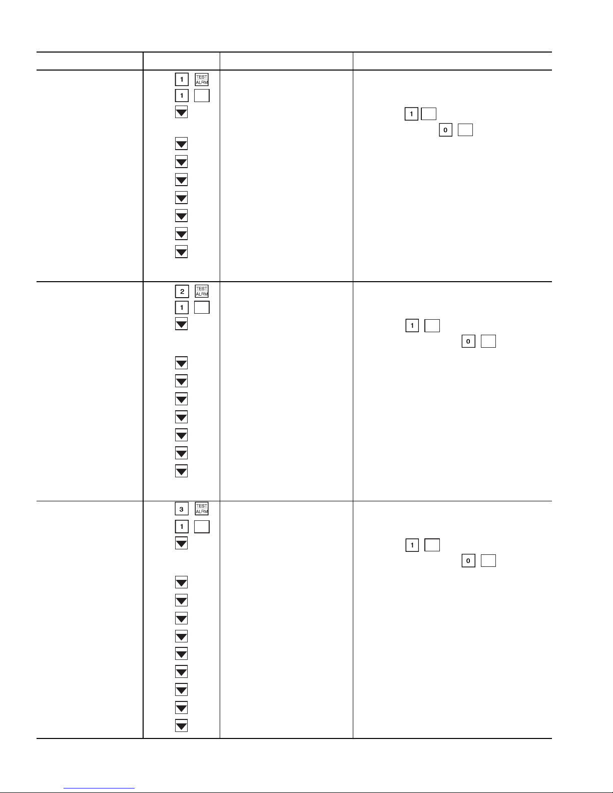
Table 17 — Test Function and Subfunction Directory
SUBFUNCTION KEYPAD ENTRY DISPLAY COMMENT
1 Circuit A Discrete Outputs
2 Circuit B Discrete Outputs
Circuit A Discrete Output Loader A1
Relay is OFF
Loader A1
ENTER
Relay is ON
Loader A2
Minimum Load Valve A
Circuit A Oil Heater
A1 Mtr. Cooling Solenoid
A2 Mtr. Cooling Solenoid
Circuit A Oil Pump
Oil Solenoid A1
Oil Solenoid A2
Circuit B Discrete Output Loader B1
Relay is OFF
Loader B1
ENTER
Relay is ON
Loader B2
Minimum Load Valve B
Similarly, use to test remaining outputs. Press
the down arrow key or to turn an output off.
NOTE: Output will display Rela y is ABSENT when not
configured
Similarly, use to test remaining outputs.
Press the down arrow key or to turn an
output off.
ENTER
ENTER
ENTER
ENTER
3 Unit Discrete Outputs
Circuit B Oil Heater
B1 Mtr. Cooling Solenoid
B2 Mtr. Cooling Solenoid
Circuit B Oil Pump
Oil Solenoid B1
Oil Solenoid B2
NOTE: Output will display Rela y is ABSENT when not
configured
Unit Discrete Output Fan 1
Relay is OFF
Fan 1
ENTER
Relay is ON
Fan 2
Similarly, use to test remaining outputs.
ENTER
Press the down arrow key or to turn an
Fan 3
output off.
Fan 4
Fan 5 Energizes Circuit A fans for 30HXA units.
Fan 6 Energizes Circuit B fans for 30HXA units.
Cooler Pump
ENTER
Condenser Pump
Cooler Heater
Alarm
Remote Alarm 1 Currently not supported.
28
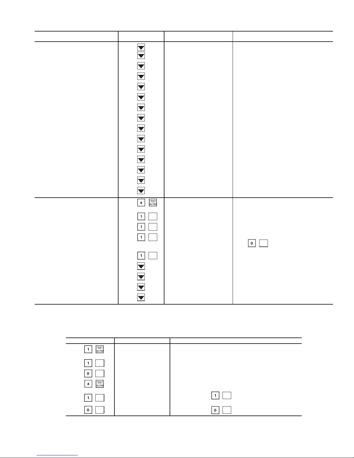
Table 17 — Test Function and Subfunction Directory (cont)
SUBFUNCTION KEYPAD ENTRY DISPLA Y COMMENT
3 Unit Discrete Outputs (cont)
4 Valves and Motormaster
ENTER
ENTER
ENTER
ENTER
Remote Alarm 2 Currently not supported.
Remote Alarm 3 Currently not supported.
Remote Alarm 4 Currently not supported.
Remote Alarm 5 Currently not supported.
Remote Alarm 6 Currently not supported.
Remote Alarm 7 Currently not supported.
Remote Alarm 8 Currently not supported.
Remote Alarm 9 Currently not supported.
Remote Alarm 10 Currently not supported.
Remote Alarm 11 Currently not supported.
Remote Alarm 12 Currently not supported.
Remote Alarm 13 Currently not supported.
Remote Alarm 14 Currently not supported.
Remote Alarm 15 Currently not supported.
Remote Alarm 16 Currently not supported.
Valves and Motor Master
Circuit A EXV Valve
Target Percent = 0%
Circuit A EXV Valve
Step in 25% increments.
Target Percent = 25%
Circuit A EXV Valve
Target Percent = 50%
Circuit A EXV Valve
Target Percent = 75%
Wait 30 seconds between each step for valv e to
stop moving.
Valve may be closed in 25% increments by keying in . Wait 30 seconds between
ENTER
each step for valve to stop moving.
Circuit A EXV Valve
Target Percent = 100%
Circuit B EXV Valve
Target Percent = 0%
Circuit A Water Valv e
Target Percent = 0%
Test same method as for Circuit A.
Test same method as for EXV valves.
Circuit A% Fan Speed Test same method as for EXV valves.
EXV — Electronic Expansion Valve
LEGEND
KEYPAD ENTRY DISPLAY RESPONSE COMMENTS
ENTER
ENTER
EXV — Electronic Expansion Valve
ENTER
ENTER
LEGEND
Circuit A Discrete Output
Loader A1
Relay is OFF
Loader A1
Relay is ON
Loader A1
Relay is OFF
Valves and Motor Master
Circuit A EXV Valve
Target Percent = 0%
Circuit A EXV Valve
Target Percent = 25%
Circuit A EXV Valve
Target Percent = 0
Circuit B% Fan Speed Test same method as for EXV valves.
Table 18 — Using Test Function
Appears on screen momentarily, then will switch to Loader A1.
Compressor Loader A1 solenoid energized
Compressor Loader A1 solenoid deenergized
Continue pressing to step to 50%, 75%, and 100%.
Wait 30 seconds between each step for valve to stop moving.
Continue pressing to step closed.
29
ENTER
ENTER
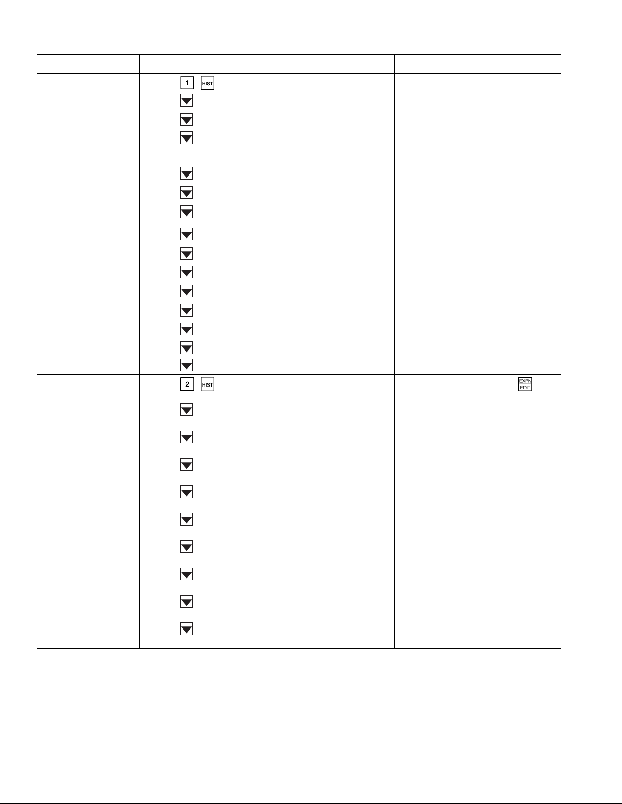
Table 19 — History Function and Subfunction Directory
SUBFUNCTION KEYPAD ENTRY DISPLAY COMMENT
1 Operating Hours
Machine Operating Hours
xxx.x hours
Machine St arts
xxx
Circuit A
Number of hours unit has at least 1 compressor running
Number of unit starts from zero capacity
2 Alarm History
Operating Hours
xxx.x hours
Compressor A1 Hours
xxx.x hours
Compressor A2 Hours
xxx.x hours
Starts
Compressor A1 Starts
xxx
Compressor A2 Starts
xxx
Circuit B
Compressor B1 Hours
xxx.x hours
Compressor B2 Hours
xxx.x hours
Starts
Compressor B1 Starts
xxx
Compressor B2 Starts
xxx
Previous Alarm 1 - description
Alarm description, time/day
of occurrence
Previous Alarm 2 - description
Alarm description, time/day
of occurrence
Previous Alarm 3 - description
Alarm description, time/day
of occurrence
Previous Alarm 4 - description
Alarm description, time/day
of occurrence
Previous Alarm 5 - description
Alarm description, time/day
of occurrence
Previous Alarm 6 - description
Alarm description, time/day
of occurrence
Previous Alarm 7 - description
Alarm description, time/day
of occurrence
Previous Alarm 8 - description
Alarm description, time/day
of occurrence
Previous Alarm 9 - description
Alarm description, time/day
of occurrence
Previous Alarm 10 - description
Alarm description, time/day
of occurrence
These values may be changed once, when
new software is downloaded or when the
PSIO-1 module is replaced (Version 4.0 and
later)
List 10 most recent alarms. Use when
necessary.
30
 Loading...