


30GTN040
Carrier 30GTN040, 30GTN060, 30GTN045, 30GTN050, 30GTN070 Operation And Service Manual
...
Controls Start-Up, Operation,
Service, and Troubleshooting
SAFETY CONSIDERATIONS
Installing, starting up, and servicing this equipment can be
hazardous due to system pressures, electrical components, and
equipment location (roof, elevated structures, etc.). Only
trained, qualified installers and service mechanics should install, start up, and service this equipment.
When working on this equipment, observe precautions in
the literature, and on tags, stickers, a nd labels attached to the
equipment, and any other safety precautions that apply. Follow
all safety codes. Wear safety glasses and work gloves. Use care
in handling, rigging, and setting this equipment, and in handling all electrical components.
Electrical shock can cause personal injury and death. Shut
off all power to this equipment during installation and service. There may be more than one disconnect switch. Tag
all disconnect locations to alert others not to restore power
until work is completed.
This unit uses a microprocessor-based electronic control
system. Do not use jumpers or other tools to short out components, or to bypass or otherwise depart from recommended procedures. Any short-to-ground of the control
board or accompanying wiring may destroy the electronic
modules or electrical components.
To prevent potential damage to heat exchanger tubes
always run fluid through heat exchangers when adding or
removing refrigerant charge. Use appropriate brine solutions in cooler fluid loops to prevent the freezing of heat
exchangers when the equipment is exposed to temperatures
below 32 F (0° C).
DO NOT VENT refrigerant relief valves within a building.
Outlet from relief valves must be vented outdoors in accordance with the latest edition of ANSI/ASHRAE (American
National Standards Institute/American Society of Heat ing,
Refrigeration and Air Conditioning Engineers) 15 (Safety
Code for Mechanical Refrigeration). The a ccumulation of
refrigerant in an enclosed space can displace oxygen and
cause asphyxiation. Provide adequate ventilation in
enclosed or low overhead areas. Inhalation of high concentrations of vapor is harmful and may cause heart irregularities, unconsciousness or death. Misuse can be fatal. Vapor
is heavier than air and reduces the amount of oxygen available for breathing. Product causes eye and skin irritation.
Decomposition products are hazardous.
30GTN,GTR040-420
30GUN,GUR040-420
Air-Cooled Reciprocating Liquid Chillers
with
Comfort
Link™ Controls
50/60 Hz
DO NOT attempt to unbraze factory joints w hen servicing
this equipment. Compressor oil is flammable and there is
no way to detect how much oil may be in any of the refrigerant lines. Cut lines with a tubing cutter as required when
performing service. Use a pan to catch any oil that may
come out of the lines and as a gage for how much oil to add
to system. DO NOT re-use compressor oil.
CONTENTS
Page
SAFETY CONSIDERATIONS
GENERAL
INTRODUCTION
MAJOR SYSTEM COMPONENTS
General
Main Base Board (MBB)
Expansion Valve (EXV) Board
Compressor Expansion Board (CXB)
Scrolling Marquee Display
Energy Management Module (EMM)
Enable/Off/Remote Contact Switch
Emergency On/Off Switch
Reset Button
Board Addresses
Control Module Communication
Carrier Comfort Network Interface
OPERATING DATA
Sensors
• T1 — COOLER LEAVING FLUID SENSOR
• T2 — COOLER ENTERING FLUID SENSOR
• T3,T4 — SATURATED CONDENSING
TEMPERATURE SENSORS
• T5,T6 — COOLER SUCTION TEMPERATURE
SENSORS
• T7,T8 — COMPRESSOR SUCTION GAS
TEMPERATURE SENSORS
• T9 — OUTDOOR-AIR TEMPERA TURE SENSOR
• T10 — REMOTE SPACE TEMPERATURE SENSOR
Thermostatic Expansion Valves (TXV)
Compressor Protection Control System
(CPCS) or Control Relay (CR)
Compressor Ground Current Protection Board
(CGF) and Control Relay (CR)
Electronic Expansion Valve (EXV)
Energy Management Module
Capacity Control
• ADDING ADDITIONAL UNLOADERS
• MINUTES LEFT FOR START
• MINUTES OFF TIME
• LOADING SEQUENCE
. . . . . . . . . . . . . . . . . . . . . . . . . . . . . . . . . . . . . . . . 2
. . . . . . . . . . . . . . . . . . . . . . . . . . . . . . . . .2,3
. . . . . . . . . . . . . . . . . . . . . . . . . . . . . . . . . . . . . . . . . . 3
. . . . . . . . . . . . . . . . . . . . . . . . . . . . . . . . . . . . . 3
. . . . . . . . . . . . . . . . . . . . . . . . . . . . . . . . . 3
. . . . . . . . . . . . . . . . . . . . . . . . . . . . .11-47
. . . . . . . . . . . . . . . . . . . . . . . . . . . . . . . . . . . . . . . . . 11
. . . . . . . . . . . . . . . . . . . . . . . . . . . . . . . . 16
. . . . . . . . . . . . . . . . . . . . . . 1
. . . . . . . . . . . . . . 3-10
. . . . . . . . . . . . . . . . . . . . . . . . . . 3
. . . . . . . . . . . . . . . . . . . . 3
. . . . . . . . . . . . . 3
. . . . . . . . . . . . . . . . . . . . . . . 3
. . . . . . . . . . . . . . 3
. . . . . . . . . . . . . . . 3
. . . . . . . . . . . . . . . . . . . . . . . . 3
. . . . . . . . . . . . . . . . . . 4
. . . . . . . . . . . . . . . 4
. . . . . . . . . . . 15
. . . . . . . . . . . . . . . . . 15
. . . . . . . . . . . . . . . . . 15
. . . . . . . . . . . . . . . 16
. . . . . . . . . . . . . . . . . . . . 16
Manufacturer reserves the right to discontinue, or change at any time, specifications or designs without notice and without incurring obligations.
Book 2
Ta b 5 c
PC 903 Catalog No. 563-025 Printed in U.S.A. Form 30GTN-3T Pg 1 3-00 Replaces: 30GTN-2T

CONTENTS (cont)
• LEAD/LAG DETERMINATION
• CAPACITY SEQUENCE DETERMINATION
• CAPACITY CONTROL OVERRIDES
Head Pressure Control
• COMFORTLINK™ UNITS (With EXV)
• UNITS WITH TXV
Pumpout
• EXV UNITS
• TXV UNITS
Marquee Display Usage
Service Test
Configuring and Operating Dual Chiller
Control
Temperature Reset
Cooling Set Point (4 to 20 mA)
Demand Limit
• DEMAND LIMIT (2-Stage Switch Controlled)
• EXTERNALLY POWERED DEMAND LIMIT
(4 to 20 mA Controlled)
• DEMAND LIMIT (CCN Loadshed Controlled)
TROUBLESHOOTING
Compressor Protection Control System
(CPCS) Board
Compressor Ground Current (CGF) Board
(30GTN,R and 30GUN,R130-210, 230A-315A,
and 330A/B-420A/B)
EXV Troubleshooting
• STEP 1 — CHECK PROCESSOR EXV OUTPUTS
• STEP 2 — CHECK EXV WIRING
• STEP 3 — CHECK RESISTANCE OF EXV MOTOR
WINDINGS
• STEP 4 — CHECK THERMISTORS THAT
CONTROL EXV
• STEP 5 — CHECK OPERATION OF THE EXV
Alarms and Alerts
SERVICE
Electronic Components
Compressors
• COMPRESSOR REMOV AL
• OIL CHARGE
Cooler
•COOLER REMOVAL
• REPLACING COOLER
• SERVICING THE COOLER
Condenser Coils
Condenser Fans
Refrigerant Feed Components
• ELECTRONIC EXPANSION VALVE (EXV)
• MOISTURE-LIQUID INDICATOR
• FILTER DRIER
• LIQUID LINE SOLENOID VALVE
• LIQUID LINE SERVICE VALVE
Thermistors
•LOCATION
• REPLACING THERMISTOR T2
• REPLACING THERMISTORS T1,T5,T6,T7, AND T8
• THERMISTORS T3 AND T4
• THERMISTOR/TEMPERATURE SENSOR CHECK
. . . . . . . . . . . . . . . . . . . . . . . . . . . . . . . . . . . . . . . . 27
. . . . . . . . . . . . . . . . . . . . . . . . . . . . . . . . . . . . . 29
. . . . . . . . . . . . . . . . . . . . . . . . . . . . . . . . . . . . . . . . 29
. . . . . . . . . . . . . . . . . . . . . . . . . . . . . . . . . . . 46
. . . . . . . . . . . . . . . . . . . . . . . . . . . . . . . . . 47
. . . . . . . . . . . . . . . . . . . . . . . . . . . . . . . . . . . . . 53-65
. . . . . . . . . . . . . . . . . . . . . . . . . . . . . . . . . . . . 53
. . . . . . . . . . . . . . . . . . . . . . . . . . . . . . . . . . . . . . . . . . . 53
. . . . . . . . . . . . . . . . . . . . . . . . . . . . . . . . . . . . . 59
. . . . . . . . . . . . . . . . . . . . . . . . . . 27
. . . . . . . . . . . . . . . . . . . . . . . . . 29
. . . . . . . . . . . . . . . . . . . . . . . . . . . . . . 43
. . . . . . . . . . . . . . . . . . . 45
. . . . . . . . . . . . . . . . . . . . . . . . . 47-52
. . . . . . . . . . . . . . . . . . . . . . . . . . . 47
. . . . . . . . . . . . . . . . . . . . . . . . . . . . 47
. . . . . . . . . . . . . . . . . . . . . . . . . . . . . . . 48
. . . . . . . . . . . . . . . . . . . . . . . . . 53
. . . . . . . . . . . . . . . . . . . . . . . . . . . . . . . . 56
. . . . . . . . . . . . . . . . . . . . . . . . . . . . . . . . . 57
. . . . . . . . . . . . . . . . . . . 58
Page
Page
Safety Devices
• COMPRESSOR PROTECTION
• LOW OIL PRESSURE PROTECTION
• CRANKCASE HEATERS
• COOLER PROTECTION
Relief Devices
• HIGH-SIDE PROTECTION
• LOW-SIDE PROTECTION
• PRESSURE RELIEF VALV ES
Other Safeties
PRE-START-UP
System Check
START-UP AND OPERATION
Actual Start-Up
Operating Limitations
• TEMPERATURES
• VOLTAGE
• MINIMUM FLUID LOOP VOLUME
• FLOW RATE REQUIREMENTS
Operation Sequence
Refrigerant Circuit
FIELD WIRING
APPENDIX A — CCN TABLES
APPENDIX B — FLUID PRESSURE DROP
CURVES
START-UP CHECKLIST
. . . . . . . . . . . . . . . . . . . . . . . . . . . . . . . . . . 64
. . . . . . . . . . . . . . . . . . . . . . . . . . . . . . . . . . . 65
. . . . . . . . . . . . . . . . . . . . . . . . . . . . . . . . . . . 65
. . . . . . . . . . . . . . . . . . . . . . . . . . . . . . . . . . 65
. . . . . . . . . . . . . . . . . . . . . . . . . . . . . . . . . . . 65
. . . . . . . . . . . . . . . . . . 66,67
. . . . . . . . . . . . . . . . . . . . . . . . . . . . . . . . . . 66
. . . . . . . . . . . . . . . . . . . . . . . . . . . 66
. . . . . . . . . . . . . . . . . . . . . . . . . . . . . 67
. . . . . . . . . . . . . . . . . . . . . . . . . . . . . . . 67
. . . . . . . . . . . . . . . . . . . . . . . . . . . . . . . . 67-70
. . . . . . . . . . . . . . . . 71-79
. . . . . . . . . . . . . . . . . . . . . . . . . . . . . . . . . . . . 80-87
. . . . . . . . . . . . . . . . .CL-1 to CL-8
GENERAL
The model 30GTN,R chillers are air-cooled chillers uti lizing refrigerant R-22. The model 30GUN,R chillers are aircooled chillers utilizing refrigerant R-134a.
Unit sizes 230-420 are modular units which are shipped as
separate sections (modules A and B). Installation instructions
specific to these units are shipped inside the individual modules. See T ables 1A and 1B for a listing of unit si zes and modular combinations. For modules 230B-315B, follow all general
instructions as noted for unit sizes 080-110. For all remaining
modules, follow instructions for unit sizes 130-210.
INTRODUCTION
This publication contains Start-Up, Service, Controls, Operation, and Troubleshooting information for the 30GTN,R040420 and 30GUN,R040-420 liquid chillers with ComfortLink
controls.
The 30GTN,R and 30GUN,R040-420 chillers are equipped
with electronic expansion valves (EXVs) or, on size 040-110
FIOP (factory-installed option) units, conventional thermostatic expansion valves (TXVs). The size 040-110 FIOP chillers
are also equipped with liquid line solenoid valves (LLSV).
NOTE: TXVs are not available on modular units.
Differences in operations and controls between standard
and 040-110 FIOP units are noted in appropriate sections in
this publication. Refer to the Installation Instructions and the
Wiring Diagrams for the appropriate unit for further details.
2
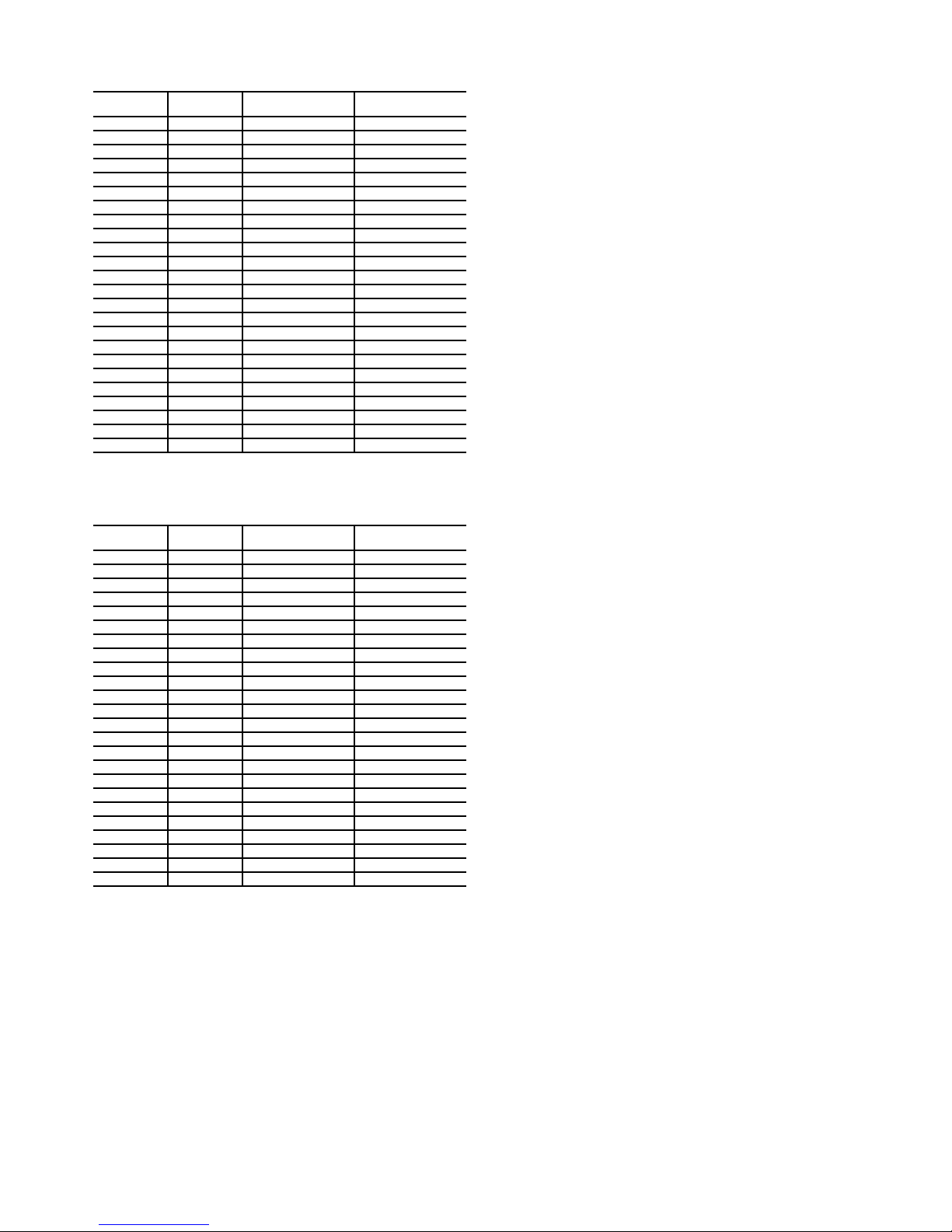
Table 1A — Unit Sizes and Modular Combinations
(30GTN,R)
UNIT
30GTN,R
040
045 45 — —
050 50 — —
060 60 — —
070 70 — —
080 80 — —
090 90 — —
100 100 — —
110 110 — —
130 125 — —
150 145 — —
170 160 — —
190 180 — —
210 200 — —
230 220 150 080
245 230 150 090
255 240 150 100
270 260 170 100
290 280 190 110
315 300 210 110
330 325 170 170
360 350 190 190/170*
390 380 210 190
420 400 210 210
*60 Hz units/50 Hz units.
NOMINAL
TONS
40 — —
SECTION A
UNIT 30GTN,R
SECTION B
UNIT 30GTN,R
Table 1B — Unit Sizes and Modular Combinations
(30GUN,R)
UNIT
30GUN,R
040 26 — —
045 28 — —
050 34 — —
060 42 — —
070 48 — —
080 55 — —
090 59 — —
100 66 — —
110 72 — —
130 84 — —
150 99 — —
170 110 — —
190 122 — —
210 134 — —
230 154 150 080
245 158 150 090
255 165 150 100
270 176 170 100
290 193 190 110
315 206 210 110
330 219 170 170
360 243 190 190/170*
390 256 210 190
420 268 210 210
*60 Hz units/50 Hz units.
NOMINAL
TONS
SECTION A
UNIT 30GUN,R
SECTION B
UNIT 30GUN,R
MAJOR SYSTEM COMPONENTS
General —
rocating chillers contain the ComfortLink™ electronic control
system that controls and monitors all operations of the chiller.
The control system is composed of several components as
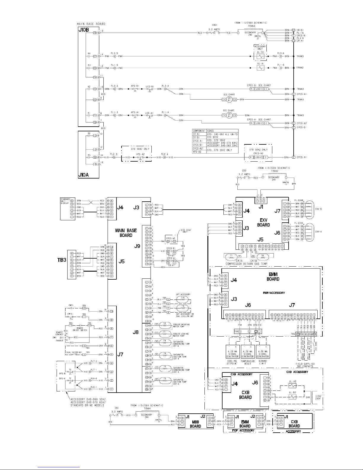
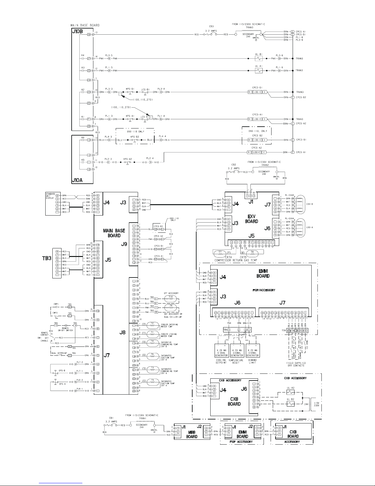
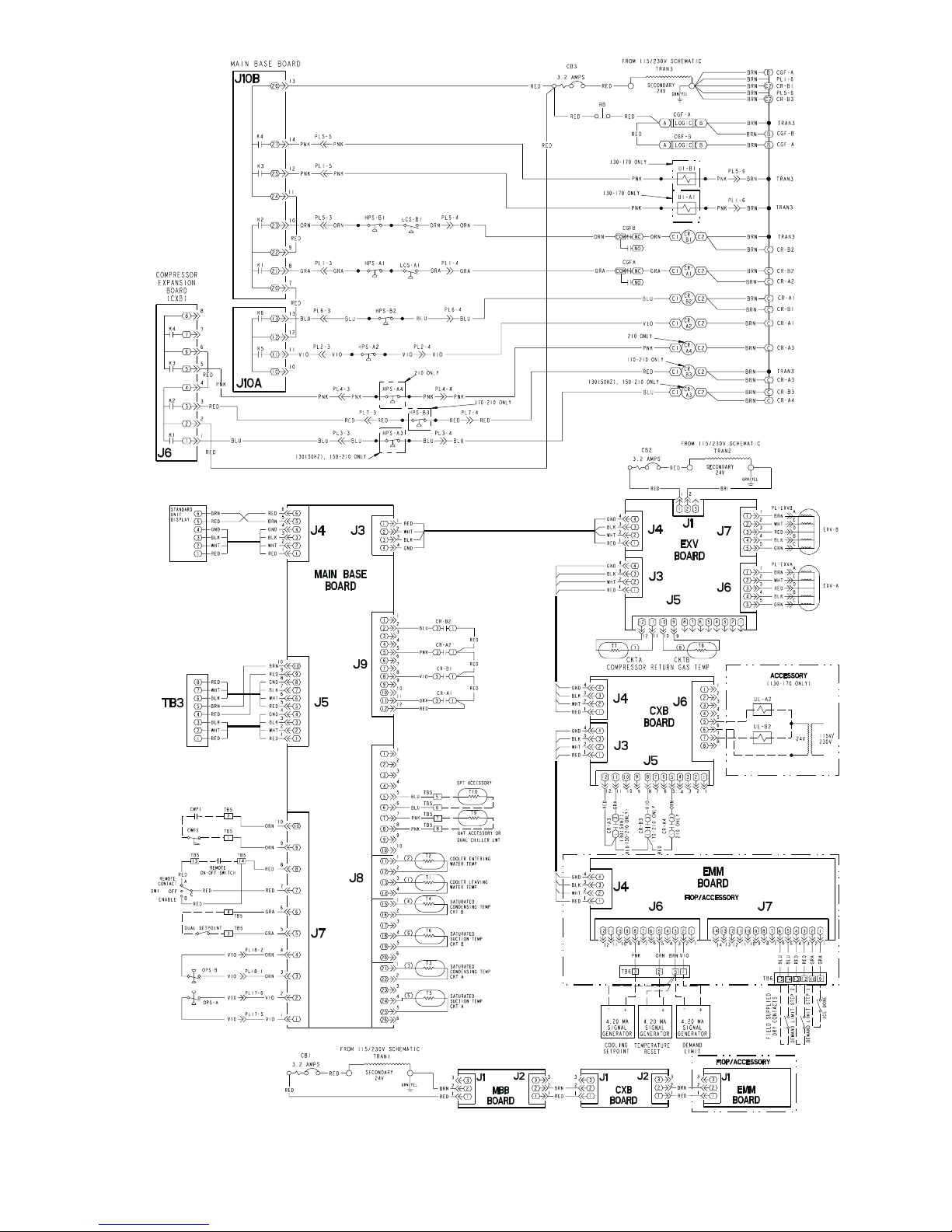
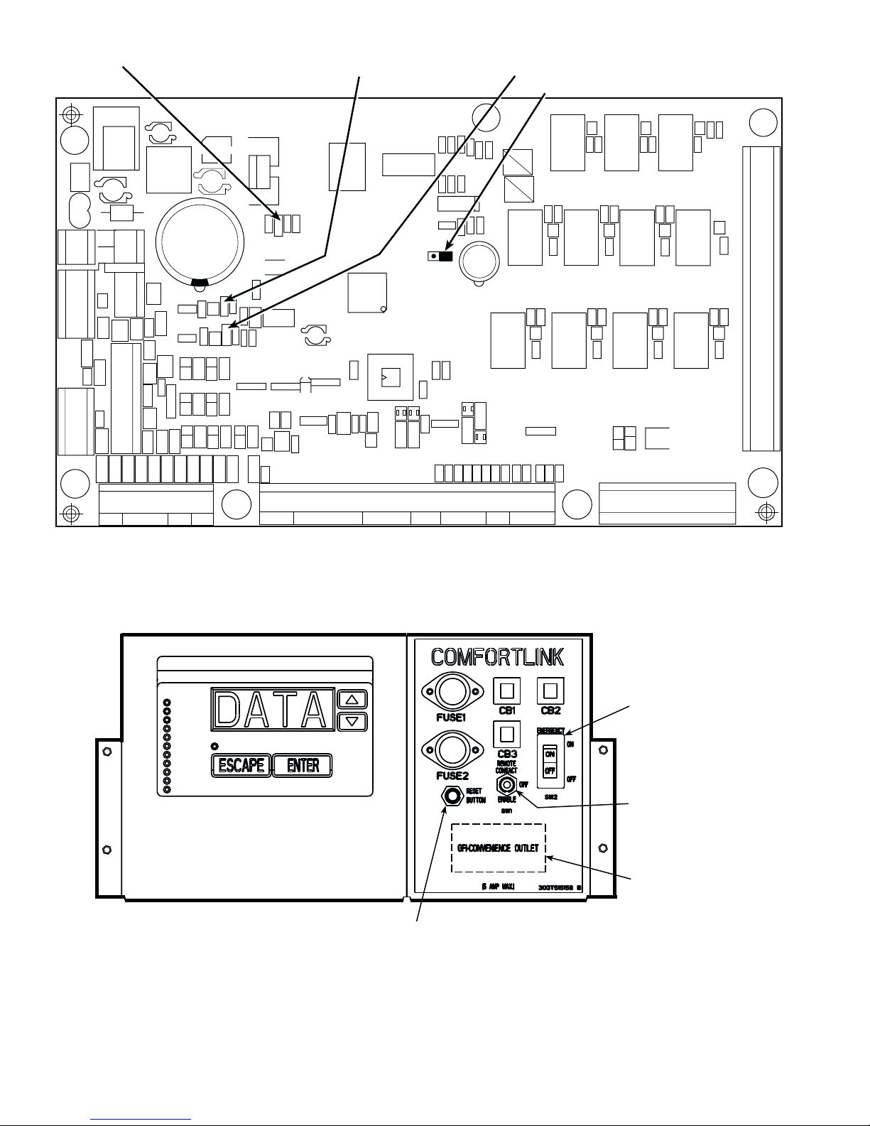
listed in the sections below. See Fig. 1 for typical control box
drawing. See Fig. 2-4 for control schematics.
Main Base Board (MBB) —
the heart of the ComfortLink control system. It contains the
major portion of operating software and controls the ope ration
of the machine. The MBB continuously monitors input/output
channel information received from its inputs and from all other
modules. The MBB receives inputs from thermistors T1-T6,
T9, and T10. See Table 2. The MBB also receives the feedback
The 30GTN,R and 30GUN,R air-cooled recip-
See Fig. 5. The MBB is
inputs from compressors A1, A2, B1 and B2, and other status
switches. See Table 3. The MBB also controls several outputs.
Relay outputs controlled by the MBB are shown in Table 4.
Information is transmitted between modules via a 3-wire communication bus or LEN (Local Equipment Network). The
CCN (Carrier Comfort Network) bus is also supported. Connections to both LEN and CCN buses are made at TB3. See
Fig. 5.
Expansion Valve (EXV) Board —
The electronic expansion valve (EXV) board receives inputs from thermistors
T7 and T8. See Table 2. The EXV board communicates with
the MBB and directly controls the expansion valves to maintain the correct compressor superheat.
Compressor Expansion Board (CXB) —
The
CXB is included as standard on sizes 150-210 (60 Hz) and 130
(50 Hz) and associated modular units. The compressor expansion board (CXB) receives the feedback inputs from compressors A3, B3 and A4. See Table 3. The CXB board communicates the status to the MBB and controls the outputs for these
compressors. An additional CXB is required for unit sizes 040110, 130 (60 Hz), 230B-315B with additional unloaders.
Scrolling Marquee Display —
This device is the keypad interface used for accessing chiller information, reading
sensor values, and testing the chiller. The marquee display is a
4-key, 4-character, 16-segment LED (light-emitting diode) display. Eleven mode LEDs are located on the display as well as
an Alarm Status LED. See Marquee Disp lay Us age section on
page 29 for further details.
Energy Management Module (EMM) —
The
EMM module is available as a factory-installed option or as a
field-installed accessory. The EMM module receives 4 to
20 mA inputs for the temperature reset, cooling set point reset
and demand limit functions. The EMM module also receives
the switch inputs for the field-installed 2-stage demand limit
and ice done functions. The EMM module communicates the
status of all inputs with the MBB, and the MBB adjusts the
control point, capacity limit, and other functions according to
the inputs received.
Enable/Off/Remote Contact Switch —
The
Enable/Off/Remote Contact switch is a 3-position switch used
to control t h e c h il le r. When switched to th e E na b le position the
chiller is under its own control. Move the switch to the Off position to shut the chiller down. Move the switch to the Remote
Contact position and a field installed dry contact can be used to
start the chiller. The contacts must be rated for dry circuit application capable of handling a 24 vac load. In the Enable and Remote Contact (dr y contacts clo sed) position s, the chiller is allowed to operate and respond to the scheduling configuration,
CCN configuration and set point data. See Fig. 6.
Emergency On/Off Switch —
The Emergency On/
Off switch should only be used when it is required to shut the
chiller off immediately. Power to the MBB, EMM, CXB, and
marquee display is interrupted when this switch is off and all
outputs from these modules will be turned off. The EXV board
is powered separately, but expansion valves will be closed as a
result of the loss of communication with the MBB. There is no
pumpout cycle when this switch is used. See Fig. 6.
Reset Button —
A reset button is located on the fuse/
circuit breaker panel for unit sizes 130-210 and associated
modules. The reset button must be pressed to reset either
Circuit Ground Fault board in the event of a trip.
Board Addresses —
The Main Base Board (MBB) has
a 3-position Instance jumper that must be set to ‘1.’ All other
boards have 4-position DIP switches. All switches are set to
‘On’ for all boards.
3
Control Module Communication
RED LED — Proper operation of the control boards can be
visually checked by looking at the red status LEDs (lightemitting diodes). When operating correctly, the red status
LEDs should be blinking in unison at a rate of once every
2 seconds. If the red LEDs are not blinking in unison, verify
that correct power is being supplied to all modules. Be sure that
the Main Base Board (MBB) is supplied with the current software. If necessary, reload current software. If the problem still
persists, replace the MBB. A red LED that is lit continuously or
blinking at a rate of once per second or faster indicates that the
board should be replaced.
GREE N LED — The MBB has one green LED. The Local
Equipment Network (LEN) LED should always be blinking
whenever power is on. All other boards have a LEN LED
which should be blinking whenever power is on. Check LEN
connections for potential communication errors at the board J3
and/or J4 connectors. Communication between modules is accomplished by a 3-wire sensor bus. These 3 wires run in parallel from module to module. The J4 connector on the MBB provides both power and communication directly to the marquee
display only .
YELLOW LED — The MBB has one yellow LED. The
Carrier Comfort Network (CCN) LED will blink during times
of network communication.
Carrier Comfort Network (CCN) Interface —
The 30GTN,R chiller units can be connected to the CCN if
desired. The communication bus wiring is a shielded,
3-conductor cable with drain wire and is supplied and installed
in the field. The system elements are connected to the communication bus in a daisy chain arrangement. The positive pin of
each system element communication connector must be wired
to the positive pins of the system elements on either side of it.
This is also required for the negative and signal ground pins of
each system element. Wiring connections for CCN should be
made at TB3. Consult the CCN Contractor ’s Manual for further information.
NOTE: Conductors and drain wire must be 20 AWG (American Wire Gage) minimum stranded, tinned copper. Individual
conductors must be insulated with PVC, PVC/nylon, vinyl,
Teflon, or polyethylene. An aluminum/polyester 100% foil
shield and an outer jacket of PVC, PVC/nylon, chrome vinyl,
or Teflon with a minimum operating temperature range of
–20 C to 60 C is required. Wire manufactured by Alpha (2413
or 5463), American (A22503), Belden (8772), or Columbia
(02525) meets the above mentioned requirements.
It is important when connecting to a CCN communication
bus that a color coding scheme be used for the entire network
to simplify the installation. It is recommended that red be used
for the signal positive, black for the signal negative, and white
for the signal ground. Use a similar scheme for cables containing different colored wires.
At each system element, the shields of its communic ation
bus cables must be tied together. If the communication bus is
entirely within one building, the resulting continuous shield
must be connected to a ground at one point only. If the communication bus cable exits from one building and enters another,
the shields must be connected to grounds at the lightning suppressor in each building where the cable enters or exits the
building (one point per building only). To connect the unit to
the network:
1. Turn off power to the control box.
2. Cut the CCN wire and strip the ends of the red (+), white
(ground), and black (–) conductors. (Substitute appropriate colors for different colored cables.)
3. Connect the red wire to (+) terminal on TB3 of the plug,
the white wire to COM terminal, and the black wire to the
(–) terminal.
4. The RJ14 CCN connector on TB3 can also be used, but is
only intended for temporary connection (for example, a
laptop computer running Service Tool).
IMPORTANT: A shorted CCN bus cable will prevent
some routines from running and may prevent the unit
from starting. If abnormal conditions occur, unplug the
connector. If conditions return to normal, check the
CCN connector and cable. Run new cable if necessary.
A short in one section of the bus can cause probl ems
with all sys tem elem en ts on th e bu s.
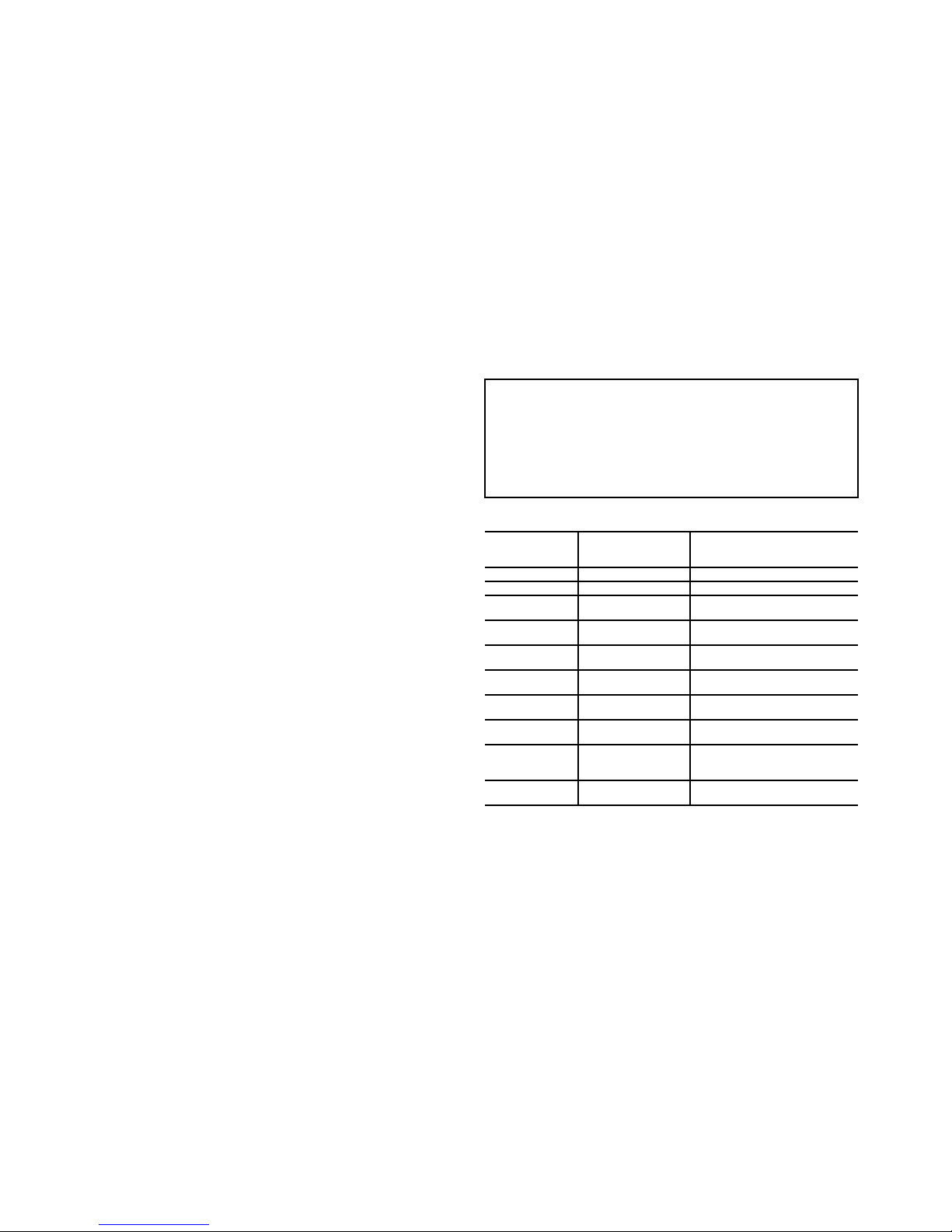
Table 2 — Thermistor Designations
THERMISTOR
NO.
T1 J8-13,14 (MBB) Cooler Leaving Fluid
T2 J8-11,12 (MBB) Cooler Entering Fluid
T3
T4
T5
T6
T7
T8
T9
T10
EXV — Electronic Expansion Valve
MBB — Main Base Board
LEGEND
PIN
CONNECTION
POINT
J8-21,22 (MBB) Saturated Condensing
J8-15,16 (MBB) Saturated Condensing
J8-24,25 (MBB) Cooler Suction Temperature,
J8-18,19 (MBB) Cooler Suction Temperature,
J5-11,12 (EXV) Compressor Suction Gas
J5-9,10 (EXV) Compressor Suction Gas
J8-7,8 (MBB) Outdoor-Air Temperature
J8-5,6 (MBB) Remote Space Temperature
THERMISTOR INPUT
Te m p e ra tu r e, C kt A
Te m p e ra tu r e, C kt B
Ckt A (EXV Only)
Ckt B (EXV Only)
Temperature, Ckt A (EXV Only)
Temperature, Ckt B (EXV Only)
Sensor or Dual Chiller LWT
Sensors (Accessory)
Sensor (Accessory)
4
STATUS SWITCH
Oil Pressure, Ckt B
Oil Pressure, Ckt A
Remote On/Off
Compressor Fault
Signal, B3
Compressor Fault
Signal, B2
Compressor Fault
Signal, B1
Compressor Fault
Signal, A4
Compressor Fault
Signal, A3
Compressor Fault
Signal, A2
Compressor Fault
Signal, A1
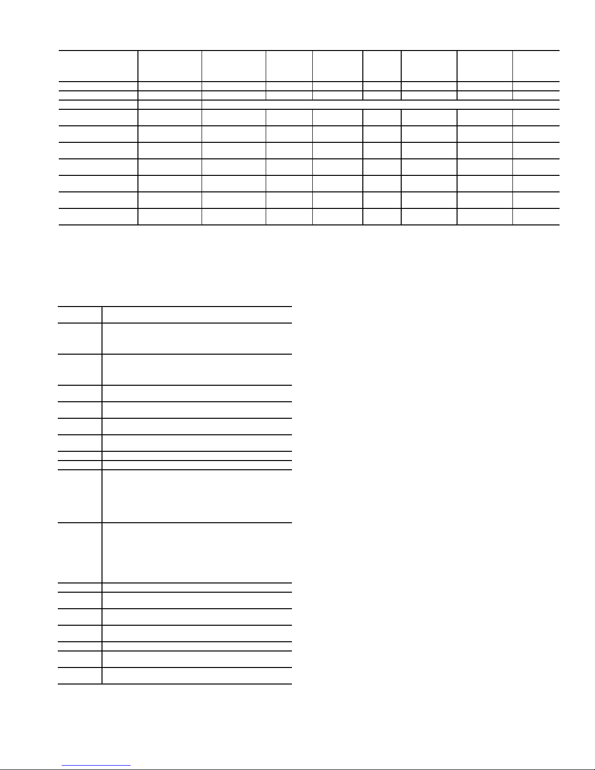
CPCS —
CR —
CXB —
MBB —
OPS —
Compressor Protection Control System
Control Relay
Compressor Expansion Board
Main Base Board
Oil Pressure Switch, Circuit A or B
Table 3 — Status Switches
PIN
CONNECTION
POINT
J7-1, 2 (MBB) Not Used* OPSB OPSB OPSB OPSB OPSB OPSB
J7-3, 4 (MBB) Not Used* OPSA OPSA OPSA OPSA OPSA OPSA
TB5-13, 14 Field-Installed Relay Closure
J5-8, 12 (CXB) Not Used Not Used Not Used Not Used Not Used CR-B3 CR-B3
J9-2, 12 (MBB) Not Used Not Used CPCS-B2 CR-B2 CR-B2 CR-B2 CR-B2
J9-8, 12 (MBB) CR/CPCS-B1† CPCS-B1 CPCS-B1 CR-B1 CR-B1 CR-B1 CR-B1
J5-5, 12 (CXB) Not Used Not Used Not Used Not Used Not Used Not Used CR-A4
J5-11, 12 (CXB) Not Used Not Used Not Used Not Used CR-A3 CR-A3 CR-A3
J9-5, 12 (MBB) Not Used CPCS-A2 CPCS-A2 CR-A2 CR-A2 CR-A2 CR-A2
J9-11, 12 (MBB) CR/CPCS-A1† CPCS-A1 CPCS-A1 CR-A1 CR-A1 CR-A1 CR-A1
LEGEND *The OPS can also be added as an accessory.
040-060 (50 Hz)
040-070 (60 Hz)
070
(50 Hz)
080, 230B
090-110,
245B-315B
†The CPCS can be added as an accessory.
130
(60 Hz)
130 (50 Hz)
150, 230A-
255A
170,190,
270A,290A,
330A/B,
360A/B, 390B
210, 315A,
390A,
420A/B
Table 4 — Output Relay
RELAY
NO.
K1(MBB)
K2 (MBB)
K3 (MBB)
K4 (MBB)
K5 (MBB)
K6 (MBB)
K7 (MBB)
K8 (MBB)
K9 (MBB)
K10 (MBB)
K11 (MBB)
K1 (CXB)
K2 (CXB)
K3 (CXB)
K4 (CXB)
K5 (CXB)
K6 (CXB)
OFM —
*And associated modular units.
†Field-installed accessory unloader.
Energize Compressor A1 and OFM1 (040-110*)
Energize Liquid Line Solenoid Valve for Ckt A (if used)
(040-110*)
Energize Compressor A1, OFM5, and OFM7 (130-210*)
Energize Compressor B1 and OFM2 (040-110*)
Energize Liquid Line Solenoid Valve for Ckt B (if used)
(040-110*)
Energize Compressor B1, OFM6, and OFM8 (130-210*)
Energize Unloader A1 (040-170*)
No Action (190-210*)
Energize Unloader B1 (040-070†, 080-170*)
No Action (190,210*)
No Action (040-060, 50 Hz; 040-070, 60 Hz)
Energize Compressor A2 (070, 50 Hz; 080-210*)
No Action (040-080*)
Energize Compressor B2 (090-210*)
Alarm
Cooler Pump
Energize First Stage of Condenser Fans:
040-050 —OFM3
060-110* — OFM3, OFM4
130 (60 Hz) — OFM1,OFM2
Energize First Stage of Ckt A Condenser Fans:
130 (50 Hz), 150,170* — OFM1
190,210* —OFM1,OFM11
Energize Second Stage of Condenser Fans:
040-050 — OFM4
060-090* — OFM5, OFM6
100,110* — OFM5,OFM6,OFM7,OFM8
130 (60 Hz) — OFM3,OFM4,OFM9,OFM10
Energize First Stage of Ckt B Condenser Fans:
130 (50 Hz), 150,170* — OFM2
190,210* — OFM2,OFM12
Hot Gas Bypass
No Action (040-110*; 130, 60 Hz)
Energize Compressor A3 (130, 50 Hz; 150-210*)
No Action (040-150*)
Energize Compressor B3 (170-210*)
Energize Compressor A4 (210*)
Energize Accessory Unloader A2 (080-110*)
Energize Accessory Unloader B2 (080-110*)
Energize Second Stage of Ckt A Condenser Fans:
130 (50 Hz), 150-210* — OFM3,OFM9
Energize Second Stage of Ckt B Condenser Fans:
130 (50 Hz), 150-210* — OFM4,OFM10
LEGEND
Outdoor-Fan Motor
DESCRIPTION
LEGEND FOR FIG. 1-4
C—
CB —
CCN —
CGF —
CHT —
CKT —
CLHR —
CPCS —
CWFS —
CWPI —
CR —
CXB —
EQUIP GND —
FB —
FC —
FCB —
FIOP —
EMM —
EXV —
FCB —
HPS —
LCS —
LEN —
MBB —
NEC —
OAT —
OPS —
PL —
PW —
SN —
SPT —
TRAN —
SW —
TB —
TDR —
TXV —
UL —
XL —
Compressor Contactor
Circuit Breaker
Carrier Comfort Network
Compressor Ground Fault
Cooler Heater Thermostat
Circuit
Cooler Heater Relay
Compressor Protection and Control System
Chilled Water Flow Switch
Chilled Water Pump Interlock
Control Relay
Compressor Expansion Board
Equipment Ground
Fuse Block
Fan Contactor
Fan Circuit Breaker
Factory-Installed Option Package
Energy Management Module
Electronic Expansion Valve
Fan Circuit Breaker
High-Pressure Switch
Loss-of-Charge Switch
Local Equipment Network
Main Base Board
National Electrical Code
Outdoor-Air Temperature
Oil Pressure Switch
Plug
Par t Wind
Sensor (Toroid)
Space Temperature
Transformer
Switch
Terminal Block
Time Delay Relay
Thermostatic Expansion Valve
Unloader
Across-the-Line
5
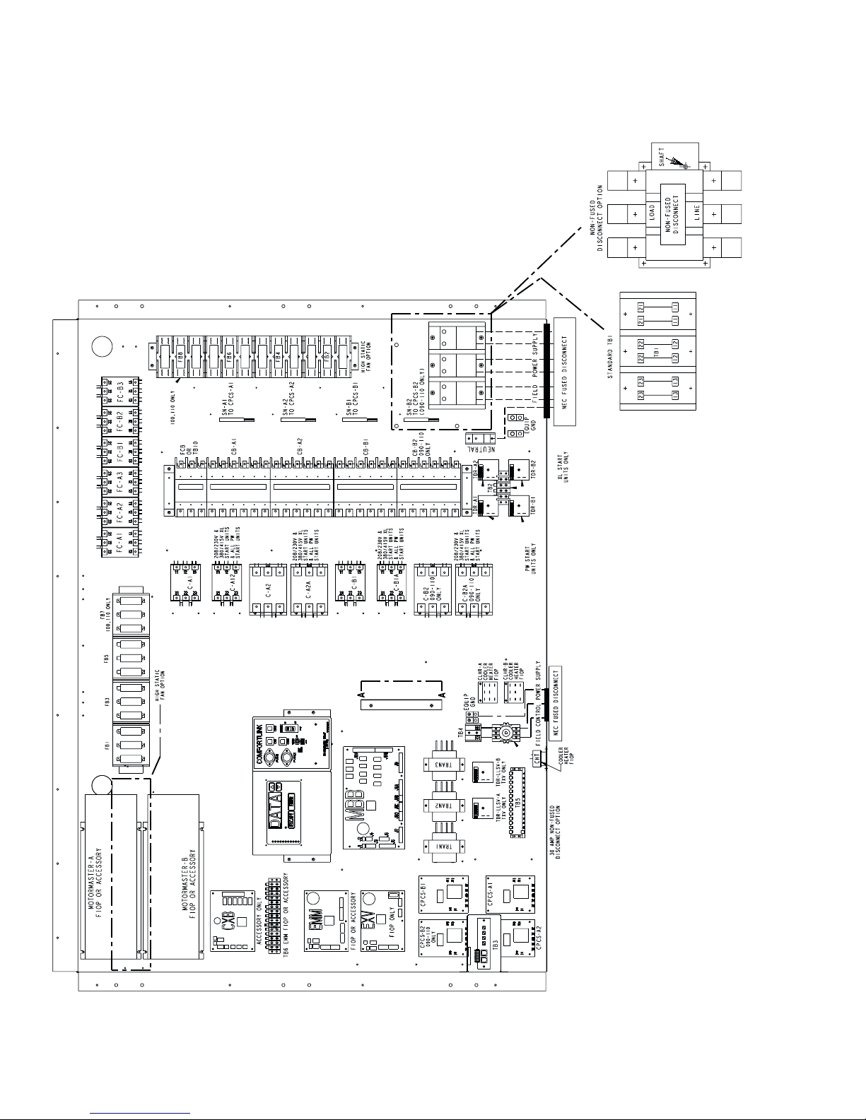
Fig. 1 — Typical Control Box (080-110 and Associated Modular Units Shown)
6
CCN
LEN
DATA
COMMUNICATION
PORT
Fig. 2 — 24 V Control Schematic, Unit Sizes 040-070
7
CCN
LEN
DATA
COMMUNICATION
PORT
/
Fig. 3 — 24 V Control Schematic, Unit Sizes 080-110, 230B-315B
Fig. 3 — 24 V Control Schematic, Unit Sizes 080-110, 230B-315B
8
CCN
LEN
DATA
COMMUNICATION
PORT
Fig. 4 — 24 V Control Schematic, Unit Sizes 130-210, 230A-315A, 330A/B-420A/B
9
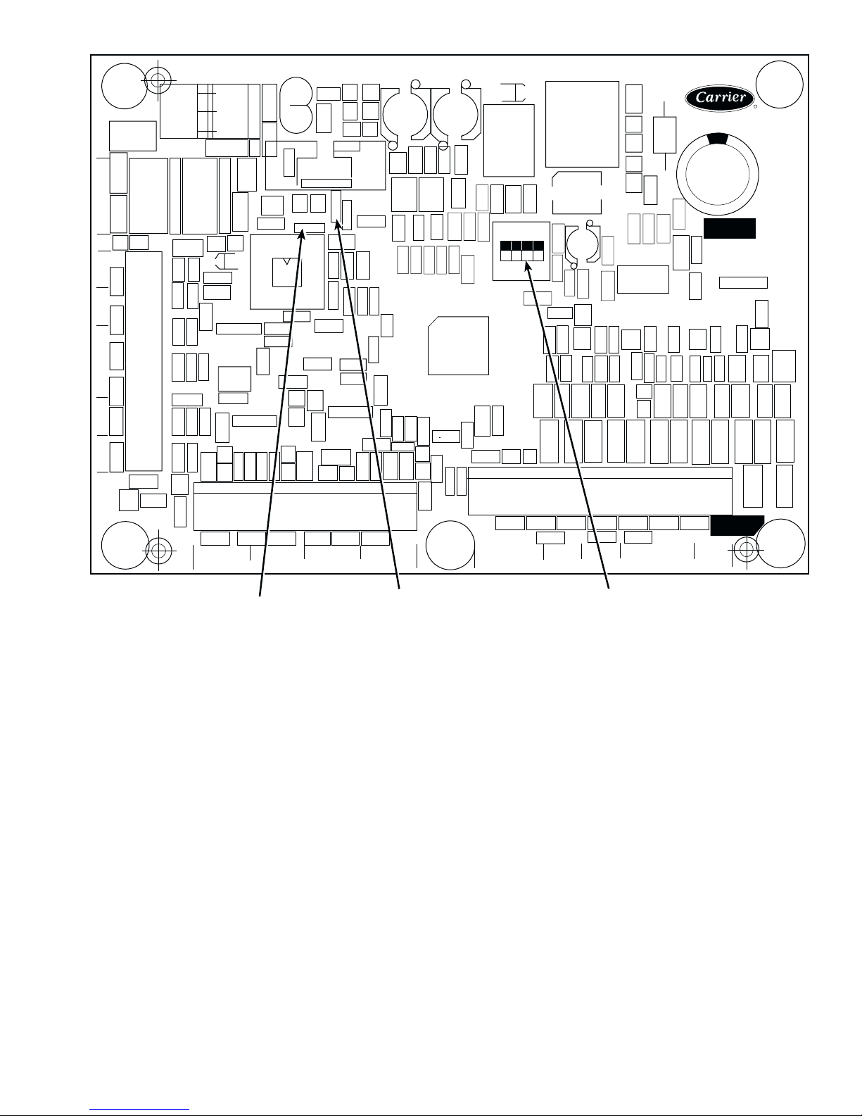
RED LED - STATUS GREEN LED -
LEN (LOCAL EQUIPMENT NETWORK)
CEPL130346-01
YELLOW LED CCN (CARRIER COMFORT NETWORK)
INSTANCE JUMPER
J1
J4
J6
J5
J2
J3
J7
LEN
CCN
STATUS
J8
Fig. 5 — Main Base Board
J10
J9
Fig. 6 — Enable/Off/Remote Contact Switch, Emergency On/Off Switch,
RESET BUTTON
(SIZES 130-210 AND
ASSOCIATED MODULES ONLY)
and Reset Button Locations
10
EMERGENCY ON/OFF
SWITCH
ENABLE/OFF/REMOTE
CONTACT SWITCH
GFI-CONVENIENCE
OUTLET ACCESSORY
ON 208/230V 460 AND
575V ONLY
OPERATING DATA
Sensors —
to sense temperatures for controlling chiller operation. See
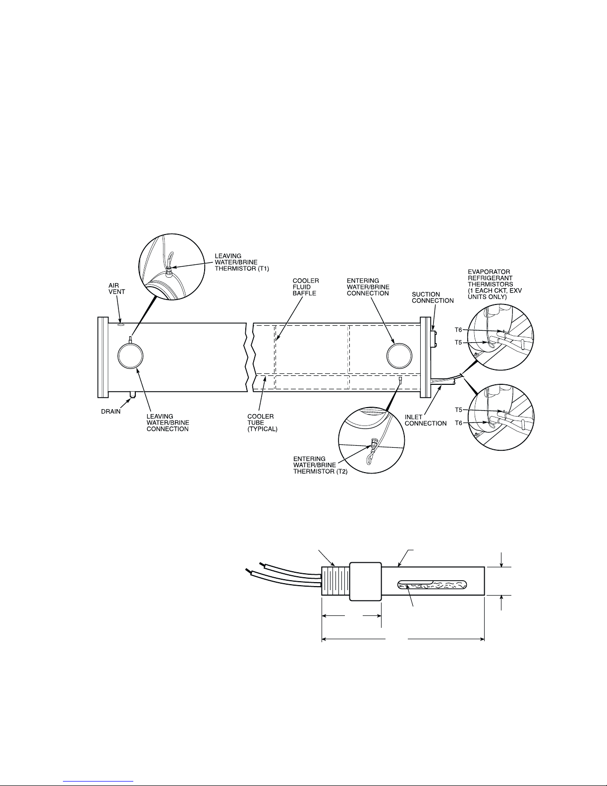
Table 2. These sensors are outlined below. See Fig. 7-10 for
thermistor locations. Thermistors T1-T9 are 5 kΩ at 77 F
(25 C). Thermistors T1, T2, T3-T6 and T7-T 9 have different
temperature versus resistance and voltage drop performance.
Thermistor T10 is 10 kΩ at 77 F (25 C) and has a different temperature vs resistance and voltage drop performance. See Thermistors section on page 59 for temperature-resistance-voltage
drop characteristics.
T1 — COOLER LEAVING FLUID SENSOR — This thermistor is located in the leaving fluid nozzle. The thermistor
probe is inserted into a friction-fit well.
T2 — COOLER ENTERING FLUID SENSOR — This
thermistor is located in the cool er shel l in th e first ba ffle spac e
in close proximity to the cooler tube bundle.
The electronic control uses 4 to 10 thermistors
T3, T4 — SATURATED CONDENSING TEMPERATURE
SENS O RS — These 2 thermistors are clamped to the outside
of a return bend of the condenser coils.
T5, T6 — COOLER SUCTION TEMPERATURE SENSORS — These thermistors are located next to the refrigerant
inlet in the cooler head, and are insert ed into a friction-fit well.
The sensor well is located directly in the refrigerant path. These
thermistors are not used on units with TXVs.
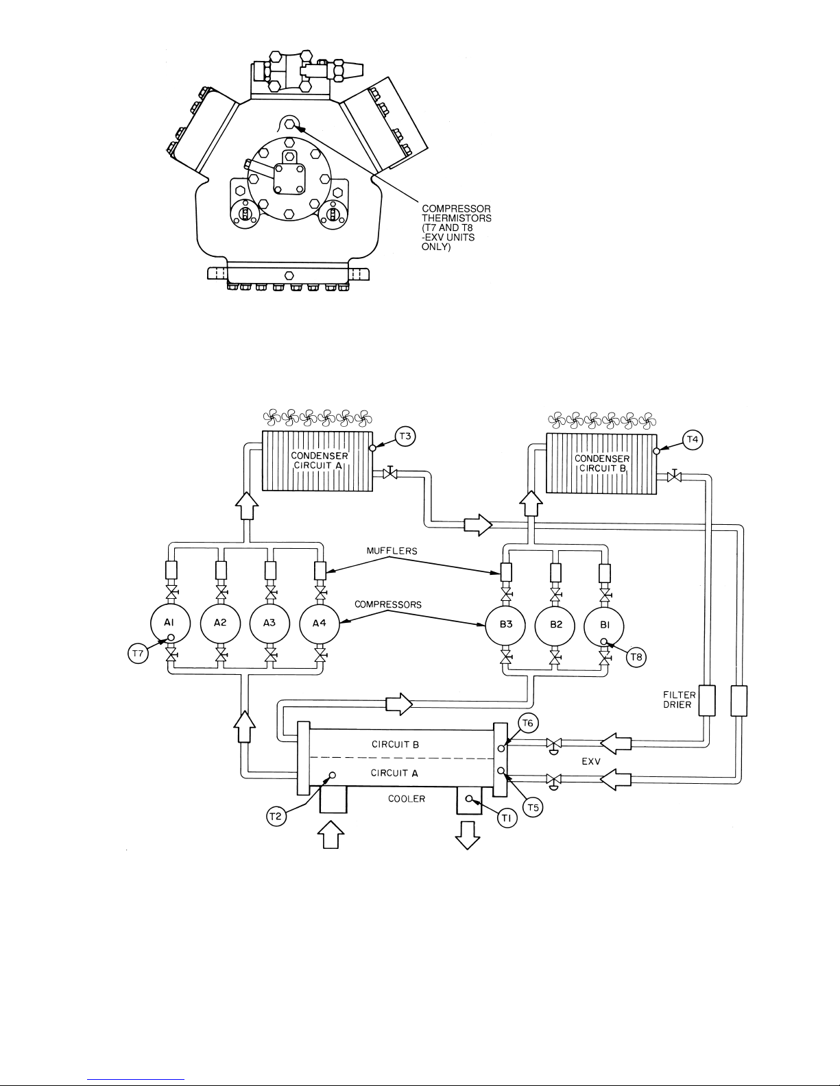
T7, T8 — COMPRESSOR SUCTION GAS TEMPERATURE SENSORS — These thermistors are located in the lead
compressor in each circuit in a suction passage aft er the refrigerant has passed over the motor and is about to enter the cylinders. These thermistors are ins erted into frict ion-fit wells. T he
sensor wells are located directly in the refrigerant path. These
thermistors are not used on units with TXVs.
T9 — OUTDOOR-AIR TEMPERATURE SENSOR —
Sensor T9 is an accessory sensor that is remotely mounted and
used for outdoor-air temperature reset.
MIN. 6” OF 22 AWG WIRES
WITH ENDS STRIPPED BACK
.25” ±1/8”
1/2 NPT MALE
THREADED ADAPTER
REF.
1.81
(46.0)
1/2” PVC SHIELD
3/16” DIA.
THERMOWELL (S.S.)
REF.
5.75
(146.1
040-110*
130-210*
REF.
.83 D
(21.1)
LEGEND
AWG —
EXV —
*And associated modular units.
American Wire Gage
Electronic Wire Gage
Fig. 7 — Cooler Thermistor Locations and Accessory Outdoor-Air Temperature Sensor Detail
11
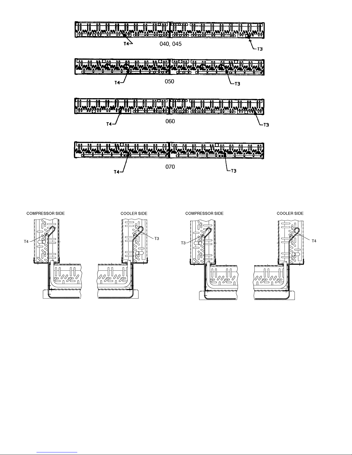
040-070
080-110 AND ASSOCIATED MODULAR UNITS* 130-210 AND ASSOCIATED MODULAR UNITS*
*When thermistor is viewed from perspective where the compressor is on the left and the cooler is on the right.
Fig. 8 — Thermistor T3 and T4 Locations
12
Electronic Expansion Valve
EXV —
Fig. 9 — Compressor Thermistor Locations (T7 and T8)
LEGEND
Fig. 10 — Typical Thermistor Location (30GTN,R and 30GUN,R 210, 315A, 390A, 420A/B Shown)
13
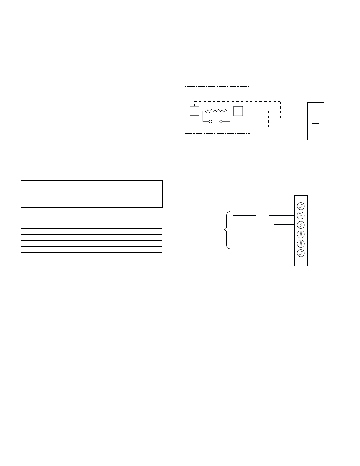
T10 — REMOTE SPACE TEMPERA TURE SENSOR —
Fig. 11 — Typical Space Temperature
Sensor Wiring
Fig. 12 — CCN Communications Bus Wiring
to Optional Space Sensor RJ11 Connector
Sensor T10 (part no. HH51BX006) is an accessory sensor that
is remotely mounted in the controlled space and used for space
temperature reset. The sensor should be installed as a
wall-mounted thermostat would be (in the conditioned space
where it will not be subjected to either a cooling or heating
source or direct exposure to sunlight, and 4 to 5 ft above the
floor). The push button override button is not supported by the
ComfortLink™ Controls.
Space temperature sensor wires are t o be connected to terminals in the unit main control box. The space temperature
sensor includes a terminal block (SEN) and a RJ11 female connector. The RJ1 1 connector is used to tap into the Carrier Comfort Network (CCN) at the sensor.
T o connect the space temperature sensor (Fig. 11):
1. Using a 20 AWG (American Wire Gage) twisted pair
conductor cable rated for the application, connect 1
wire of the twisted pair to one SEN terminal and connect the other wire to the other SEN terminal located
under the cover of the space temperature sensor.
2. Connect the other ends of the wires to terminals 5 a nd 6
on TB5 located in the unit control box.
Units on the CCN can be monitored from the space at the
sensor through the RJ11 connector, if desired. To wire the RJ11
connector into the CCN (Fig. 12):
2. Insert and secure the red (+) wire to terminal 5 of the
space temperature sensor terminal block.
3. Insert and secure the white (ground) wire to terminal 4 of
the space temperature sensor.
4. Insert and secure the black (–) wire to terminal 2 of the
space temperature sensor.
5. Connect the other end of the communication bus cable to
the remainder of the CCN communication bus.
SPT (T10) PART NO. HH51BX006
SENSOR
SEN
SEN
TB5
5
6
IMPORTANT: The cable selected for the RJ11 connector wiring MUST be identical to the CCN communication bus wire used for the entire network. Refer to table
below for acceptable wiring.
MANUFACTURER
Alpha
American
Belden
Columbia
Manhattan
Quabik
Regular Wiring Plenum Wiring
1895 —
A21451 A48301
8205 884421
D6451 —
M13402 M64430
6130 —
PART NO.
1. Cut the CCN wire and strip ends of the red (+), white
(ground), and black (–) conductors. (If another wire
color scheme is used, strip ends of appropriate wires.)
TO CCN
TERMINALS
ON TB3
AT UNIT
CCN+
CCN GND
CCN-
T-55 SPACE
SENSOR
6
5
4
3
2
1
14
Thermostatic Expansion Valves (TXV) —
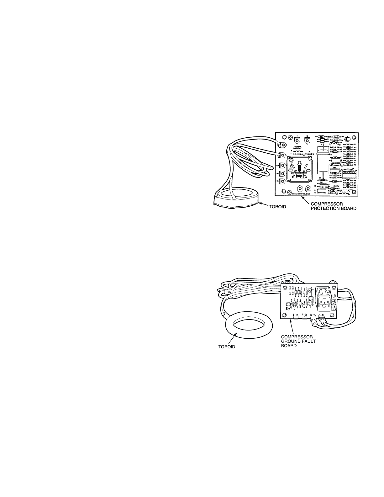
Fig. 13 — Compressor Protection Control
System Module — Sizes 040-110
Fig. 14 — Compressor Ground Fault Module
— Sizes 130-210
30GTN,R and 30GUN,R 040-110 units are available from the
factory with conventional TXVs with liquid line solenoids. The
liquid line solenoid valves are not intended to be a mechanical
shut-off. When service is required, use the liquid line service
valve to pump down the system.
NOTE: This option is not available for modular units.
The TXV is set at the factory to maintain approximately 8 to
12° F (4.4 to 6.7° C) suction superheat leaving the cooler by
metering the proper amount of refrigerant into the cooler. All
TXVs are adjustable, but should not be adjusted unless abso-
lutely necessary. When TXV is used, thermistors T5, T 6, T7,
and T8 are not required.
The TXV is designed to limit the cooler saturated suctio n
temperature to 55 F (12.8 C). This makes it possible for unit to
start at high cooler fluid temperatures without overloading the
compressor.
Compressor Protection Control System (CPCS
[CPCS — Standard on Sizes 080-110 and
Optional on Sizes 040-070]) or Control Relay
(CR) — 30GTN,R and 30GUN,R 040-110 —
compressor has its own CPCS module or CR. See Fig. 13 for
CPCS module. The CPCS or CR is used to control and protect
the compressors and crankcase heaters. The CPCS and CR provide the following functions:
• compressor contactor control/crankcase heater
• crankcase heater control
• compressor ground current protection (CPCS only)
• status communication to processo r board
• high-pressure protection
One large relay is located on the CPCS board. This relay
controls the crankcase heater and compressor contactor, and
also provides a set of signal contacts that the microprocessor
monitors to determine the operating status of the compressor. If
the processor board determines that the compressor is not operating properly through the signal contacts, it will lock the compressor off by deenergizing the proper 24-v control relay on the
relay board. The CPCS board contains logic that can detect if
the current-to-ground of any compressor winding exceeds
2.5 amps. If this condition occurs, the CPCS shuts down the
compressor.
A high-pressure switch is wired in series between the MBB
and the CR or CPCS. On compressor A1 and B1 a loss-ofcharge switch is also wired in series with the high-pressure
switch. If the high-pressure switch opens during operation of a
compressor, the compressor will be stopped, the failure will be
detected through the signal contacts, and the compressor will
be locked off. If the le ad compressor in eithe r circuit is shut
down by the high-pressure switch, loss-of-charge switch,
ground current protector, or oil safety switch, all compressors
in that circuit are shut down.
NOTE: The CR operates the same as the CPCS, except the
ground current circuit protection is not provided.
Compressor Ground Current Protection
Board (CGF) and Control Relay (CR) —
30GTN,R and 30GUN,R 130-210, and associated modular
units (see T a ble 1) contain one compressor ground current protection board (CGF) (see Fig. 14) for each refrigeration circuit.
The CGF contains logic that can detect if the current-to-ground
Model
Each
The
of any compressor winding exceeds 2.5 amps. If this occurs,
the lead compressor in that circuit is shut down along with other compressors in that circuit.
A high-pressure switch is wired in series between the MBB
and the CR. On compressor A1 and B1 a loss-of-charge switch
is also wired in series with the high-pressure swit ch. The lead
compressor in each circuit also has the CGF contacts described
above. If any of these switches open during operation of a compressor, the CR relay is deenergized, stopping the compressor
and signaling the processor at the MBB-J9 inputs to lock out
the compressor. If the lead compressor in either circuit is shut
down by high-pressure switch, compressor ground fault, oil
pressure switch, or the loss-of-charge switch, all compressors
in that circuit are also shut down.
15
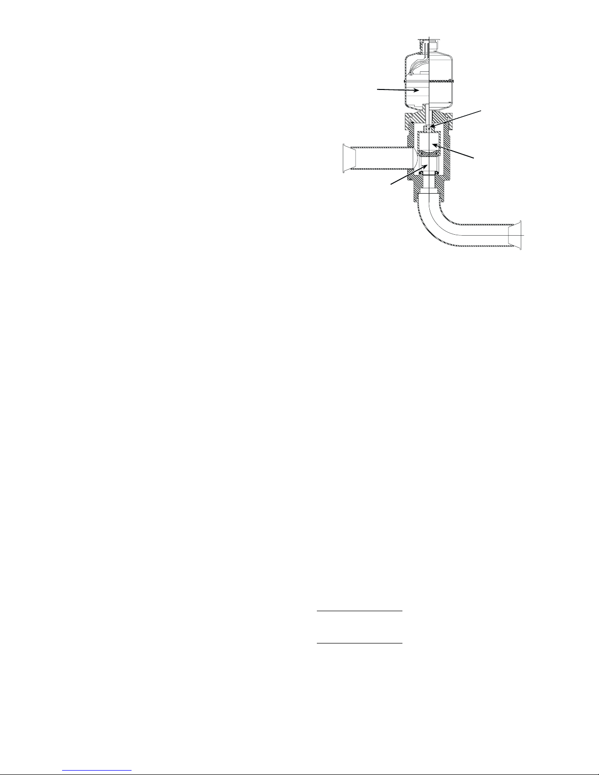
Electronic Expansion Valve (EXV) (See
Fig. 15 — Electronic Expansion Valve (EXV)
Fig. 15) —
EXV. This device eliminates the use of the liquid line solenoid
pumpdown at unit shutdown. An O-ring has been added t o bottom of orifice a ssem bly to com plete a se al i n the v alve on s hutdown. This is not a mechanical shut-off. When service is
required, use the liquid line service val ve to pump down the
system.
High pressure refrigerant enters bottom of val ve where it
passes through a group of machined slots in side of orifice assembly. As refrigerant passes through the orifice, it drops in
pressure. To control flow of refrigerant, the sleeve slides up and
down along orifice assembly, modulating the size of orifice.
The sleeve is moved by a linear stepper motor that moves in increments controlled directly by the processor. As stepper motor
rotates, the moti on is translated into li near movement of lead
screw. There are 1500 discrete steps with this combination. The
valve orifice begins to be exposed at 320 steps. Since there is
not a tight seal with the orifice and the sleeve, the minimum position for operation is 120 steps.
Two thermistors are used to determine suction superheat .
One thermistor is located in the cooler and the othe r is locat ed
in the cylinder end of the compressor after refrigerant has
passed over the motor. The difference between the 2 thermistors is the suction superheat. These machines are set up to
provide approximately 5 to 7 F (2.8 to 3.9 C) superheat leaving
the cooler. Motor cooling accounts for approximately 22 F
(12.2 C) on 30GTN,R units and 16 F (8.9 C) on 30GUN,R
units, resulting in a superheat entering compressor cylinders of
approximately 29 F (16.1 C) for 30GTN,R units and 23 F
(12.8 C) for 30GUN,R units.
Because the valves are controlled by the EXV module, it is
possible to track the position of the valve. Valve position can be
used to control head pressure and system refrigerant charge.
During initial start-up, the EXV module will drive each
valve fully closed. After initialization period, valve position is
controlled by the EXV module and the MBB.
The EXV is used to limit the maximum cooler saturated
suction temperature to 55 F (12.8 C). This makes it possible for
the chiller to start at high cooler fluid temperatures without
overloading the compressor.
Energy Management Module (Fig. 16) —
factory-installed option or field-installed accessory is used for
the following types of temperature reset, demand limit, and/or
ice featu res :
• 4 to 20 mA leaving fluid temperature reset (requires
field-supplied 4 to 20 mA generator)
• 4 to 20 mA cooling set point reset (requires field-
supplied 4 to 20 mA generator)
• Discrete inputs for 2-step demand limit (requires field-
supplied dry contacts capable of handling a 5 vdc, 1 to
20 mA load)
• 4 to 20 mA demand limit (requires field-supplied 4 to
20 mA gener ator)
• Discrete input for Ice Done switch (requires field-
supplied dry contacts capable of handling a 5 vdc, 1 to
20 mA load)
See Demand Limit and Temperature Reset sections on
pages 46 and 43 for further details.
Capacity Control —
pressors, unloaders, and hot gas bypass solenoids to maintain
the user-configured leaving chilled fluid temperature set point.
Entering fluid temperature is used by the Main Base Board
(MBB) to determine the temperature drop across the cooler and
is used in determining the optimum time to add or subtract capacity stages. The chilled fluid temperature set point can be automatically reset by the return tem perature reset or space and
outdoor-air temperature reset features. It can also be reset from
Standard units are equipped with a bottom seal
This
The control system cycles com-
STEPPER
MOTOR (12 VDC)
LEAD SCREW
PISTON SLEEVE
ORIFICE ASSEMBLY
(INSIDE PISTON SLEEVE)
an external 4 to 20 mA signal (requires Energy Management
Module FIOP/accessory).
With the automatic lead-lag feature i n the unit, the control
determines which circuit will start first, A or B. At the first call
for cooling, the lead compressor crankcase heater will be deenergized, a condenser fan will start, and the compressor will start
unloaded.
NOTE: The automatic lead-lag feature is only operative when
an even number of unloaders is present. The 040-070 units
require an accessory unloader to be installed on the B1 compressor for the lead-lag feature to be in effect.
If the circuit has been off for 15 minutes, and the unit is a
TXV unit, liquid line solenoid will remain closed during startup of each circuit for 15 seconds while the cooler and suction
lines are purged of any liquid refrigerant. For units with EXVs,
the lead compressor will be signaled to start. The EXV will remain at minimum position for 10 seconds before it is allowed
to modulate.
After the purge period, the EXV will begin to meter the refrigerant, or the liquid line solenoid will open allowing the
TXV to meter the refrigerant to the cooler. If the off-time is less
than 15 minutes, the EXV will be opened as soon as the compressor starts.
The EXVs will open gradually to provide a controlled startup to prevent liquid flood-back to the compressor. During startup, the oil pressure switch is bypassed for 2 minutes to allow
for the transient changes during start-up. As additional stages
of compression are required, the processor control will add
them. See Tables 5A and 5B.
If a circuit is to be stopped, the control will first start to close
the EXV or close the liquid line solenoid valve.
For units with TXVs
, the lag compressor(s) will be shut
down and the lead compressor will continue to operate for
10 seconds to purge the cooler of any refrigerant.
For units with EXVs
, the lag compressor(s) will be shut
down and the lead compressor will continue to run. After t he
lag compressor(s) has shut down, the EXV is signaled to close.
The lead compressor will remain on for 10 seconds after the
EXV is closed.
During both algorithms (TXV and EXV), all diagnostic
conditions will be honored. If a safety trip or alarm condition is
detected before pumpdown is complete, the circuit will be shut
down.
16
CEBD430351-0396-01C
PWR
J1
J2
J4 J3
J5
RED LED - STATUS
LEN
STATUS
J6
GREEN LED LEN (LOCAL EQUIPMENT NETWORK)
Fig. 16 — Energy Management Module
J7
ADDRESS
DIP SWITCH
TEST 1
CEPL130351-01
TEST 2
The capacity control algorithm runs every 30 seconds. The
algorithm attempts to maintain the leaving chilled water temperature at the control point. Each time it runs, the control reads
the entering and leaving fluid temperatures. The control determines the rate at which conditions are changing and calculates
2 variables based on these conditions. Next, a capacity ratio is
calculated using the 2 variables to determine whether or not to
make any changes to the current stages of capacity. This ratio
value ranges from –100 to + 100%. If the next stage of capacity
is a compressor, the control starts (stops) a compressor when
the ratio reaches +100% (–100%). If the next stage of capacity
is an unloader, the control deenergizes (energizes) an unloader
when the ratio reaches +60% (–60%). Unloaders are allowed to
cycle faster than compressors, to minimize the number of starts
and stops on each compressor. A delay of 90 seconds occurs after each capacity step change.
17

Table 5A — Part Load Data Percent Displacement, Standard Units
UNIT
30GTN,R
30GUN,R
040 (60 Hz)
040 (50 Hz)
045 (60 Hz)
045 (50 Hz)
050 (60 Hz)
050 (50 Hz)
060 (60 Hz)
060 (50 Hz)
070 (60 Hz)
070 (50 Hz)
080, 230B (60 Hz)
080, 230B (50 Hz)
090, 245B (60 Hz)
090, 245B (50 Hz)
100, 255B,
270B (60 Hz)
*Unloaded compressor.
NOTE: These capacity control steps may vary due to lag compressor sequencing.
CONTROL
STEPS
125A1*——
250A1——
375A1*, B1——
4 100 A1,B1 ——
124A1*——
247A1——
376A1*,B1——
4 100 A1,B1 ——
131A1*——
244A1——
387A1*,B1——
4 100 A1,B1 ——
128A1*——
242A1——
387A1*,B1——
4 100 A1,B1 ——
133A1*——
250A1——
383A1*,B1——
4 100 A1,B1 ——
119A1*——
227A1——
365A1*,B1——
473A1,B1——
5 92 A1*,A2,B1 ——
6 100 A1,A2,B1 ——
1 22 A1* 30 B1*
234A144B1
3 52 A1*,B1* 52 A1*,B1*
4 67 A1*,B1 63 A1,B1*
5 78 A1,B1 78 A1,B1
6 89 A1*,A2,B1 85 A1,A2,B1*
7 100 A1,A2,B1 100 A1,A2,B1
1 17 A1* 25 B1*
225A138B1
3 42 A1*,B1* 42 A1*,B1*
4 54 A1*,B1 50 A1, B1*
5 62 A1,B1 62 A1,B1
6 79 A1*,A2,B1* 79 A1*,A2,B1*
7 92 A1*,A2,B1 88 A1,A2,B1*
8 100 A1,A2,B1 100 A1,A2,B1
1 18 A1* 18 B1*
227A127B1
3 35 A1*,B1* 35 A1*,B1*
4 44 A1*,B1 44 A1,B1
5 53 A1,B1 53 A1,B1
6 56 A1*,A2,B1* 62 A1*,B1*,B2
7 65 A1*,A2,B1 71 A1,B1*,B2
8 74 A1,A2,B1 80 A1,B1,B2
9 82 A1*,A2,B1*,B2 82 A1*,A2,B1*,B2
10 91 A1*,A2,B1,B2 91 A1,A2,B1*,B2
11 100 A1,A2,B1,B2 100 A1,A2,B1,B2
114A114B1*
221A121B1
3 29 A1*,B1* 29 A1*,B1*
4 36 A1*,B1 36 A1,B1*
5 43 A1,B1 43 A1,B1
6 61 A1*,A2,B1* 53 A1*,B1*,B2
7 68 A1*,A2,B1 60 A1,B1*,B2
8 75 A1,A2,B1 67 A1,B1,B2
9 86 A1*,A2,B1*,B2 86 A1*,A2,B1*,B2
10 93 A1*,A2,B1,B2 93 A1,A2,B1*,B2
11 100 A1,A2,B1,B2 100 A1,A2,B1,B2
1 16 A1* 16 A1*
223A123A1
3 31 A1*,B1* 31 A1*,B1*
4 39 A1*,B1 39 A1*,B1
5 46 A1,B1 46 A1,B1
6 58 A1*,A2,B1* 58 A1*,A2,B1*
7 66 A1*,A2,B1 66 A1*,A2,B1
8 73 A1,A2,B1 73 A1,A2,B1
9 85 A1*,A2,B1*,B2 85 A1*,A2,B1*,B2
10 92 A1*,A2,B1,B2 92 A1*,A2,B1,B2
11 100 A1,A2,B1,B2 100 A1,A2,B1,B2
LOADING SEQUENCE A LOADING SEQUENCE B
% Displacement
(Approx)
Compressors
% Displacement
(Approx)
Compressors
18

Table 5A — Part Load Data Percent Displacement, Standard Units (cont)
UNIT
30GTN,R
30GUN,R
100, 255B
270B (50 Hz)
110, 290B,
315B (60 Hz)
110, 290B,
315B (50 Hz)
130 (60 Hz)
130 (50 Hz)
150, 230A, 245A,
255A (60 Hz)
*Unloaded compressor.
NOTE: These capacity control steps may vary due to lag compressor sequencing.
CONTROL
STEPS
1 13 A1* 13 B1*
220A120B1
3 26 A1*,B1* 26 A1*,B1*
4 33 A1,B1 33 A1,B1
5 40 A1,B1 40 A1,B1
6 57 A1*,A2,B1* 57 A1*,B1*,B2
7 63 A1*,A2,B1 63 A1,B1*,B2
8 70 A1,A2,B1 70 A1,B1,B2
9 87 A1*,A2,B1*,B2 87 A1*,A2,B1*,B2
10 93 A1*,A2,B1,B2 93 A1,A2,B1*,B2
11 100 A1,A2,B1,B2 100 A1,A2,B1,B2
1 14 A1* 14 B1*
221A121B1
3 29 A1*,B1* 29 A1*,B1*
4 36 A1*,B1 36 A1,B1*
5 43 A1,B 43 A1,B1
6 61 A1*,A2,B1* 53 A1*,B1*,B2
7 68 A1*,A2,B1 60 A1,B1*,B2
8 75 A1,A2,B1 67 A1,B1,B2
9 86 A1*,A2,B1*,B2 86 A1*,A2,B1*,B2
10 93 A1*,A2,B1,B2 93 A1,A2,B1*,B2
11 100 A1,A2,B1,B2 100 A1,A2,B1,B2
1 17 A1* 17 B1*
225A125B1
3 33 A1*,B1* 33 A1*,B1*
4 42 A1*,B1 42 A1,B1*
5 50 A1,B1 50 A1,B1
6 58 A1*,A2,B1* 58 A1*,B1*,B2
7 67 A1*,A2,B1 67 A1,B1*,B2
8 75 A1,A2,B1 75 A1,B1,B2
9 83 A1*,A2,B1*,B2 83 A1*,A2,B1*,B2
10 92 A1*,A2,B1,B2 92 A1,A2,B1*,B2
11 100 A1,A2,B1,B2 100 A1,A2,B1,B2
1 14 A1* 14 B1*
221A121B1
3 28 A1*,B1* 28 A1*,B1*
4 35 A1*,B1 35 A1,B1*
5 42 A1,B1 42 B1,B1
6 58 A1*,A2,B1* 58 A1*,B1*,B2
7 64 A1*,A2,B1 64 A1,B1*,B2
8 71 A1,A2,B1 71 A1,G1,B2
9 87 A1*,A2,B1*,B2 87 A1*,A2,B1*,B2
10 93 A1*,A2,B1,B2 93 A1,A2,B1*,B2
11 100 A1,A2,B1,B2 100 A1,A2,B1,B2
1 10 A1* 16 B1*
214A125B1
3 26 A1*,B1* 26 A1*,B1*
4 35 A1*,B1 31 A1,B1*
5 39 A1,B1 39 A1,B1
6 44 A1*,A2,B1* 51 A1*,B1*,B2
7 53 A1*,A2,B1 56 A1,B1*,B2
8 57 A1,A2,B1 64 A1,B1,B2
9 69 A1*,A2,B1*,B2 69 A1*,A2,B1*,B2
10 78 A1*,A2,B1,B2 75 A1,A2,B1*,B2
11 82 A1,A2,B1,B2 82 A1,A2,B1,B2
12 87 A1*,A2,A3,B1*,B2 87 A1*,A2,A3,B1*,B2
13 96 A1*,A2,A3,B1,B2 91 A1,A2,A3,B1*,B2
14 100 A1,A2,A3,B1,B2 100 A1,A2,A3,B1,B2
1 11 A1* 18 B1*
215A127B1
3 29 A1*,B1* 29 A1*,B1*
4 38 A1*,B1 33 A1,B1*
5 42 A1,B1 42 A1,B1
6 44 A1*,A2,B1* 55 A1*,B1*,B2
7 53 A1*,A2,B1 60 A1,B1*,B2
8 58 A1,A2,B1 69 A1,B1,B2
9 71 A1*,A2,B1*,B2 71 A1*,A2,B1*,B2
10 80 A1*,A2,B1,B2 75 A1,A2,B1*,B2
11 85 A1,A2,B1,B2 85 A1,A2,B1,B2
12 86 A1*,A2,A3,B1*,B2 86 A1*,A2,A3,1*,B2
13 95 A1*,A2,A3,B1,B2 91 A1,A2,A3,B1*,B2
14 100 A1,A2,A3,B1,B2 100 A1,A2,A3,B1,B2
LOADING SEQUENCE A LOADING SEQUENCE B
% Displacement
(Approx)
Compressors
% Displacement
(Approx)
Compressors
19

Table 5A — Part Load Data Percent Displacement, Standard Units (cont)
UNITT
30GTN,R
30GUN,R
150, 230A, 245A,
255A (50 Hz)
170, 270A,
330A/B (60 Hz)
170, 270A,
330A/B,
360B (50 Hz)
190, 290A, 360A/B,
390B (60 Hz)
190, 290A, 360A,
390B (50 Hz)
210, 315A, 390A,
420A/B (60 Hz)
210, 315A, 390A,
420A/B (50 Hz)
*Unloaded compressor.
NOTE: These capacity control steps may vary due to lag compressor sequencing.
CONTROL
STEPS
1
2
3
4
5
6
7
8
9
10
11
12
13
14
1
2
3
4
5
6
7
8
9
10
11
12
13
14
15
16
17
1
2
3
4
5
6
7
8
9
10
11
12
13
14
15
16
17
1
2
3
4
5
6
1
2
3
4
5
6
1
2
3
4
5
6
7
1
2
3
4
5
6
7
% Displacement
LOADING SEQUENCE A LOADING SEQUENCE B
(Approx)
13
20
26
33
40
46
53
60
66
73
80
86
93
100
11
17
23
28
33
39
45
50
56
61
67
73
78
83
89
95
100
9
14
19
23
28
33
37
42
52
57
61
72
76
81
91
96
100
13
25
41
56
78
100
17
33
50
67
83
100
11
25
36
56
67
86
100
9
26
35
51
67
84
100
Compressors
A1*,B1*
A1*,B1
A1,B1
A1*,A2,B1*
A1*,A2,B1
A1,A2,B1
A1*,A2,B1*,B2
A1*,A2,B1,B2
A1,A2,B1,B2
A1*,A2,A3,B1*,B2
A1*,A2,A3,B1,B2
A1,A2,A3,B1,B2
A1*,B1*
A1*,B1
A1,B1
A1*,A2,B1*
A1*,A2,B1
A1,A2,B1
A1*,A2,B1*,B2
A1*,A2,B1,B2
A1,A2,B1,B2
A1*,A2,A3,B1*,B2
A1*,A2,A3,B1,B2
A1,A2,A3,B1,B2
A1*,A2,A3,B1*,B2,B3
A1*,A2,A3,B1,B2,B3
A1,A2,A3,B1,B2,B3
A1*,B1*
A1*,B1
A1,B1
A1*,A2,B1*
A1*,A2,B1
A1,A2,B1
A1*,A2,B1*,B2
A1*,A2,B1,B2
A1,A2,B1,B2
A1*,A2,A3,B1*,B2
A1*,A2,A3,B1,B2
A1,A2,A3,B1,B2
A1*,A2,A3,B1*,B2,B3
A1*,A2,A3,B1,B2,B3
A1,A2,A3,B1,B2,B3
A1,B1
A1,A2,B1
A1,A2,B1,B2
A1,A2,A3,B1,B2
A1,A2,A3,B1,B2,B3
A1,B1
A1,A2,B1
A1,A2,B1,B2
A1,A2,A3,B1,B2
A1,A2,A3,B1,B2,B3
A1,B1
A1,A2,B1
A1,A2,B1,B2
A1,A2,A3,B1,B2
A1,A2,A3,B1,B2,B3
A1,A2,A3,A4,B1,B2,B3
A1,B1
A1,A2,B1
A1,A2,B1,B2
A1,A2,A3,B1,B2
A1,A2,A3,B1,B2,B3
A1,A2,A3,A4,B1,B2,B3
A1*
A1
A1*
A1
A1*
A1
A1
A1
A1
A1
% Displacement
(Approx)
13
20
26
33
40
46
53
60
66
73
80
86
93
100
11
17
23
28
33
39
45
50
56
61
67
73
78
83
89
95
100
9
14
19
23
28
38
43
47
52
57
61
72
76
81
91
96
100
13
25
41
56
78
100
17
33
50
67
83
100
14
25
44
56
75
86
100
16
26
42
51
67
84
100
Compressors
B1*
B1
A1*,B1*
A1,B1*
A1,B1
A1*,B1*,B2
A1,B1*,B2
A1,B1,B2
A1*,A2,B1*,B2
A1,A2,B1*,B2
A1,A2,B1,B2
A1*,A2,A3,B1*,B2
A1,A2,A3,B1*,B2
A1,A2,A3,B1,B2
B1*
B1
A1*,B1*
A1,B1*
A1,B1
A1*,B1*,B2
A1,B1*,B2
A1,B1,B2
A1*,A2,B1*,B2
A1,A2,B1*,B2
A1,A2,B1,B2
A1*,A2,B1*,B2,B3
A1,A2,B1*,B2,B3
A1,A2,B1,B2,B3
A1*,A2,A3,B1*,B2,B3
A1,A2,A3,B1*,B2,B3
A1,A2,A3,B1,B2,B3
B1*
B1
A1*,B1*
A1,B1*
A1,B1
A1*,B1*,B2
A1,B1*,B2
A1,B1,B2
A1*,A2,B1*,B2
A1,A2,B1*,B2
A1,A2,B1,B2
A1*,A2,B1*,B2,B3
A1,A2,B1*,B2,B3
A1,A2,B1,B2,B3
A1*,A2,A3,B1*,B2,B3
A1,A2,A3,B1*,B2,B3
A1,A2,A3,B1,B2,B3
B1
A1,B1
A1,B1,B2
A1,A2,B1,B2
A1,A2,B1,B2,B3
A1,A2,A3,B1,B2,B3
A1,A2,A3,B1,B2,B3
A1,A2,A3,B1,B2,B3
A1,A2,A3,A4,B1,B2,B3
A1,A2,A3,B1,B2,B3
A1,A2,A3,A4,B1,B2,B3
B1
A1,B1
A1,B1,B2
A1,A2,B1,B2
A1,A2,B1,B2,B3
B1
A1,B1
A1,B1,B2
A1,A2,B1,B2
A1,A2,B1,B2,B3
B1
A1,B1
A1,B1,B2
A1,A2,B1,B2
A1,A2,B1,B2,B3
20

Table 5B — Part Load Data Percent Displacement, With Accessory Unloaders
UNIT
30GTN,R
30GUN,R
040 (60 Hz)
040 (50 Hz)
045 (60 Hz)
045 (50 Hz)
050 (60 Hz)
050 (50 Hz)
060 (60 Hz)
060 (50 Hz)
070 (60 Hz)
070 (50 Hz)
080, 230B (60 Hz)
080, 230B (50 Hz)
090, 245B (60 Hz)
*Unloaded compressor.
†Two unloaders, both unloaded.
NOTE: Some control steps will be skipped if they do not increase chiller capacity when staging up or decrease chiller capacity when staging down.
CONTROL
STEPS
1 25 A1* 25 B1*
250A150B1
3 75 A1*,B1 75 A1,B1*
4 100 A1,B1 100 A1,B1
1 24 A1* 21 B1†
247A137B1*
345A1*,B1† 53 B1
4 61 A1*,B1* 45 A1*,B1†
5 84 A1,B1* 61 A1*,B1*
6 100 A1,B1 84 A1,B1*
7 ——100 A1,B1
118A1† 20 B1†
2 31 A1* 38 B1*
344A156B1
438A1†,B1† 38 A1†,B1†
551A1*,B1† 51 A1*,B1†
6 69 A1*,B1* 69 A1*,B1*
7 82 A1,B1* 82 A1,B1*
8 100 A1,B1 100 A1,B1
115A1† 18 B1†
2 28 A1* 38 B1*
342A158B1
433A1†,B1† 33 A1†,B1†
547A1*,B1† 47 A1*,B1†
6 67 A1*,B1* 67 A1*,B1*
7 80 A1,B1* 80 A1,B1*
8 100 A1,B1 100 A1,B1
116A1† 16 B1†
2 33 A1* 33 B1*
350A150B1
431A1†,B1† 31 A1†,B1†
549A1*,B1† 49 A1*,B1†
6 66 A1*,B1* 66 A1*,B1*
7 83 A1,B1* 83 A1,B1*
8 100 A1,B1 100 A1,B1
111A1† 15 B1†
2 19 A1* 31 B1*
327A147B1
425A1†,B1† 25 A1†,B1†
533A1*,B1† 33 A1*,B1†
6 49 A1*,B1* 49 A1*,B1*
7 57 A1,B1* 57 A1,B1*
8 73 A1,B1 73 A1,B1
984A1†,A2,B1 68 A1,A2,B1†
10 92 A1*,A2,B1 84 A1,A2,B1*
11 100 A1,A2,B1 100 A1,A2,B1
111A1† 15 B1†
2 22 A1* 30 B1*
334A144B1
441A1†,B1* 48 A1,B1†
555A1†,B1 63 A1,B1*
6 67 A1*,B1 78 A1,B1
7 78 A1,B1 85 A1,A2,B1*
8 89 A1*,A2,B1 100 A1,A2,B1
9 100 A1,A2,B1 ——
18A1† 13 B1†
2 17 A1* 25 B1*
325A138B1
433A1†,B1* 50 A1,B1*
546A1†,B1 62 A1,B1
6 54 A1*,B1 67 A1*,A2,B1†
7 62 A1,B1 75 A1,A2,B1†
871A1†,A2,B1* 88 A1,A2,B1*
984A1†,A2,B1 100 A1,A2,B1
10 92 A1*,A2,B1 ——
11 100 A1,A2,B1 ——
19A1† 9B1†
2 18 A1* 18 B1*
327A127B1
435A1†,B1 35 A1,B1†
5 44 A1*,B1 44 A1,B1*
6 53 A1,B1 53 A1,B1
756A1†,A2,B1 62 A1,B1†,B2
8 65 A1*,A2,B1 71 A1,B1*,B2
9 74 A1,A2,B1 80 A1,B1,B2
10 82 A1†,A2,B1,B2 82 A1,A2,B1†,B2
11 91 A1*,A2,B1,B2 91 A1,A2,B1*,B2
12 100 A1,A2,B1,B2 100 A1,A2,B1,B2
LOADING SEQUENCE A LOADING SEQUENCE B
% Displacement
(Approx)
Compressors
% Displacement
(Approx)
Compressors
21

Table 5B — Part Load Data Percent Displacement, With Accessory Unloaders (cont)
UNIT
30GTN,R
30GUN,R
090, 245B (50 Hz)
100, 255B,
270B (60 Hz)
100, 255B,
270B (50 Hz)
110, 290B,
315B (60 Hz)
110, 290B,
315B (50 Hz)
*Unloaded compressor.
†Two unloaders, both unloaded.
NOTE: These capacity control steps may vary due to lag compressor sequencing.
CONTROL
STEPS
17A1† 7B1†
2 14 A1* 14 B1*
321A121B1
429A1†,B1 29 A1,B1†
5 36 A1*,B1 36 A1,B1*
6 43 A1,B1 43 A1,B1
749A1†,A2,B1† 46 A1*,B1†,B2
854A1†,A2,B1* 53 A1,B1†,B2
961A1†,A2,B1 60 A1,B1*,B2
10 68 A1*,A2,B1 67 A1,B1,B2
11 75 A1,A2,B1 72 A1†,A2,B1†,B2
12 79 A1†,A2,B1*,B2 79 A1*,A2,B1†,B2
13 86 A1†,A2,B1,B2 86 A1,A2,B1†,B2
14 93 A1*,A2,B1,B2 93 A1,A2,B1*,B2
15 100 A1,A2,B1,B2 100 A1,A2,B1,B2
18A1† 8B1†
2 16 A1* 16 B1*
323A123B1
431A1†,B1 31 A1,B1†
5 39 A1*,B1 39 A1,B1*
6 46 A1,B1 46 A1,B1
750A1†,A2,B1* 50 A1*,B1†,B2
858A1†,A2,B1 58 A1,B1†,B2
9 66 A1*,A2,B1 66 A1,B1*,B2
10 73 A1,A2,B1 73 A1,B1,B2
11 77 A1†,A2,B1*,B2 77 A1*,A2,B1†,B2
12 85 A1†,A2,B1,B2 85 A1,A2,B1†,B2
13 92 A1*,A2,B1,B2 92 A1,A2,B1*,B2
14 100 A1,A2,B1,B2 100 A1,A2,B1,B2
17A1† 7B1†
2 13 A1* 13 B1*
320A120B1
426A1†,B1 26 A1,B1†
5 33 A1*,B1 33 A1,B1*
6 40 A1,B1 40 A1,B1
743A1†,A2,B1† 43 A1†,B1†,B2
850A1†,A2,B1* 50 A1*,B1†,B2
957A1†,A2,B1 57 A1,B1†,B2
10 63 A1*,A2,B1 63 A1,B1*,B2
11 70 A1,A2,B1 70 A1,B1,B2
12 74 A1†,A2,B1†,B2 74 A1†,A2,B1†,B2
13 80 A1†,A2,B1*,B2 80 A1*,A2,B1†,B2
14 89 A1†,A2,B1,B2 87 A1,A2,B1†,B2
15 93 A1*,A2,B1,B2 93 A1,A2,B1*,B2
16 100 A1,A2,B1,B2 100 A1,A2,B1,B2
17A1† 7B1†
2 14 A1* 14 B1*
321A121B1
429A1†,B1 29 A1,B1†
5 36 A1*,B1 36 A1,B1*
6 43 A1,B1 43 A1,B1
747A1†,A2,B1† 46 A1*,B1†,B2
854A1†A2,B1* 53 A1,B1†,B2
961A1†,A2,B1 60 A1,B1*,B2
10 68 A1*,A2,B1 67 A1,B1,B2
11 75 A1,A2,B1 72 A1†,A2,B1†,B2
12 79 A1†,A2,B1*,B2 79 A1*,A2,B1†,B2
13 86 A1†,A2,B1,B2 86 A1,A2,B1†,B2
14 93 A1*,A2,B1,B2 93 A1,A2,B1*,B2
15 100 A1,A2,B1,B2 100 A1,A2,B1,B2
18A1† 8B1†
2 17 A1* 17 B1*
325A125B1
433A1†,B1 33 A1,B1†
5 42 A1*,B1 42 A1,B1*
6 50 A1,B1 50 A1,B1
758A1†,A2,B1 58 A1,B1†,B2
8 67 A1*,A2,B1 67 A1,B1*,B2
9 75 A1,A2,B1 75 A1,B1,B2
10 83 A1†,A2,B1,B2 83 A1,A2,B1†,B2
11 92 A1*,A2,B1,B2 92 A1,A2,B1*,B2
12 100 A1,A2,B1,B2 100 A1,A2,B1,B2
LOADING SEQUENCE A LOADING SEQUENCE B
% Displacement
(Approx)
Compressors
% Displacement
(Approx)
Compressors
22

Table 5B — Part Load Data Percent Displacement, with Accessory Unloaders (cont)
UNIT
30GTN,R
30GUN,R
130 (60 Hz)
130 (50 Hz)
150, 230A, 245A,
255A (60 Hz)
150, 230A, 245A,
255A (50 Hz)
*Unloaded compressor.
Two unloaders, both unloaded.
NOTE: These capacity control steps may vary due to lag compressor sequencing.
CONTROL
STEPS
1
2
3
4
5
6
7
8
9
10
11
12
13
14
15
16
17
1
2
3
4
5
6
7
8
9
10
11
12
13
14
15
16
17
18
19
1
2
3
4
5
6
7
8
9
10
11
12
13
14
15
16
17
1
2
3
4
5
6
7
8
9
10
11
12
13
14
15
LOADING SEQUENCE A LOADING SEQUENCE B
% Displacement
(Approx)
8
14
21
22
28
35
42
44
51
58
64
71
73
80
87
93
100
6
10
14
22
31
35
39
40
49
53
57
65
74
78
82
83
91
96
100
6
11
15
24
33
38
42
49
53
58
66
75
80
85
91
95
100
6
13
20
26
33
40
46
53
60
66
73
80
86
93
100
Compressors
A1†,A2,B1†
A1†,A2,B1*
A1†,A2,B1†,B2
A1†,A2,B1*,B2
A1†,A2,B1,B2
A1*,A2,B1,B2
A1,A2,B1,B2
A1†,A2,B1*
A1†,A2,B1*,B2
A1†,A2,B1,B2
A1*,A2,B1,B2
A1,A2,B1,B2
A1†,A2,A3,B1*,B2
A1†,A2,A3,B1,B2
A1*,A2,A3,B1,B2
A1,A2,A3,B1,B2
A1†,A2,B1*,B2
A1†,A2,B1,B2
A1*,A2,B1,B2
A1,A2,B1,B2
A1†,A2,A3,B1,B2
A1*,A2,A3,B1,B2
A1,A2,A3,B1,B2
A1†,A2,B1,B2
A1*,A2,B1,B2
A1,A2,B1,B2
A1†,A2,A3,B1,B2
A1*,A2,A3,B1,B2
A1,A2,A3,B1,B2
A1†
A1*
A1
A1†,B1*
A1†,B1
A1*,B1
A1,B1
A1†,A2,B1
A1,A2,B1
A1,A2,B1†
A1†
A1*
A1
A1†,B1*
A1†,B1
A1*,B1
A1,B1
A1†,A2,B1
A1*,A2,B1
A1,A2,B1
A1†
A1*
A1
A1†,B1*
A1†,B1
A1*,B1
A1,B1
A1†,A2,B1
A1*,A2,B1
A1,A2,B1
A1†
A1*
A1
A1†,B1
A1*,B1
A1,B1
A1†,A2,B1
A1*,A2,B1
A1,A2,B1
% Displacement
(Approx)
8
14
21
22
28
35
42
44
51
58
64
71
73
80
87
93
100
8
16
25
31
39
43
47
56
64
65
74
82
83
91
100
—
—
—
—
9
18
27
33
42
46
51
60
69
75
86
91
100
—
—
—
—
6
13
20
26
33
40
46
53
60
66
73
80
86
93
100
Compressors
B1†
B1*
B1
A1*,B1†
A1,B1†
A1,B1*
A1,B1
A1†,B1†,B2
A1*,B1†,B2
A1,B1†,B2
A1,B1*,B2
A1,B1,B2
A1†,A2,B1†,B2
A1*,A2,B1†,B2
A1,A2,B1†,B2
A1,A2,B1*,B2
A1,A2,B1,B2
B1†
B1*
B1
A1,B1*
A1,B1
A1*,B1†,B2
A1,B1†,B2
A1,B1*,B2
A1,B1,B2
A1,A2,B1†,B2
A1,A2,B1*,B2
A1,A2,B1,B2
A1,A2,A3,B1†,B2
A1,A2,A3,B1*,B2
A1,A2,A3,B1,B2
—
—
—
—
B1†
B1*
B1
A1,B1*
A1,B1
A1*,B1†,B2
A1,B1†,B2
A1,B1*,B2
A1,B1,B2
A1,A2,B1*,B2
A1,A2,B1,B2
A1,A2,A3,B1*,B2
A1,A2,A3,B1,B2
—
—
—
—
B1†
B1*
B1
A1,B1†
A1,B1*
A1,B1
A1,B1†,B2
A1,B1*,B2
A1,B1,B2
A1,A2,B1†,B2
A1,A2,B1*,B2
A1,A2,B1,B2
A1,A2,A3,B1†,B2
A1,A2,A3,B1*,B2
A1,A2,A3,B1,B2
23
Table 5B — Part Load Data Percent Displacement, With Accessory Unloaders (cont)
UNIT
30GTN,R
30GUN,R
170, 270A,
330A/B (60 Hz)
170, 270A,
330A/B, 360B (50 Hz)
190, 290A, 360A/B,
390B (60 Hz)
*Unloaded compressor.
†Two unloaders, both unloaded.
NOTE: These capacity control steps may vary due to lag compressor sequencing.
CONTROL
STEPS
1
2
3
4
5
6
7
8
9
10
11
12
13
14
15
16
17
18
19
20
21
22
23
1
2
3
4
5
6
7
8
9
10
11
12
13
14
15
16
17
18
19
20
21
22
23
24
25
26
1
2
3
4
5
6
7
8
9
10
11
12
13
14
15
16
17
% Displacement
LOADING SEQUENCE A LOADING SEQUENCE B
(Approx)
6
11
17
17
23
28
33
34
39
45
50
51
56
61
67
67
73
78
83
84
89
95
100
5
9
14
14
19
23
28
28
33
37
42
43
48
52
57
61
63
67
72
76
81
82
87
91
96
100
9
13
18
21
25
33
37
41
49
53
56
71
74
78
93
96
100
Compressors
A1†,B1*
A1†,B1
A1*,B1
A1,B1
A1†,A2,B1*
A1†,A2,B1
A1*,A2,B1
A1,A2,B1
A1†,A2,B1*,B2
A1†,A2,B1,B2
A1*,A2,B1,B2
A1,A2,B1,B2
A1†,A2,A3,B1*,B2
A1†,A2,A3,B1,B2
A1*,A2,A3,B1,B2
A1,A2,A3,B1,B2
A1†,A2,A3,B1*,B2,B3
A1†,A2,A3,B1,B2,B3
A1*,A2,A3,B1,B2,B3
A1,A2,A3,B1,B2,B3
A1†,B1*
A1†B1
A1*,B1
A1,B1
A1†,A2,B1*
A1†,A2,B1
A1*,A2,B1
A1,A2,B1
A1†,A2,B1†,B2
A1†,A2,B1*,B2
A1†,A2,B1,B2
A1*,A2,B1,B2
A1,A2,B1,B2
A1†A2,A3,B1†,B2
A1†,A2,A3,B1*,B2
A1†,A2,A3,B1,B2
A1*,A2,A3,B1,B2
A1,A2,A3,B1,B2
A1†,A2,A3,B1†,B2,B3
A1†,A2,A3,B1*,B2,B3
A1†,A2,A3,B1,B2,B3
A1*,A2,A3,B1,B2,B3
A1,A2,A3,B1,B2,B3
A1*,B1*
A1*,B1
A1,B1
A1*,A2,B1*
A1*,A2,B1
A1,A2,B1
A1*,A2,B1*,B2
A1*,A2,B1,B2
A1,A2,B1,B2
A1*,A2,A3,B1*,B2
A1*,A2,A3,B1,B2
A1,A2,A3,B1,B2
A1*,A2,A3,B1*,B2,B3
A1*,A2,A3,B1,B2,B3
A1,A2,A3,B1,B2,B3
A1†
A1*
A1
A1†
A1*
A1
A1*
A1
% Displacement
(Approx)
6
11
17
17
23
28
33
34
39
45
50
51
56
61
67
67
73
78
83
84
89
95
100
5
9
14
14
19
23
28
29
34
38
43
47
48
52
57
61
63
67
72
76
81
82
87
91
96
100
9
13
18
21
25
33
37
41
49
53
56
71
74
78
93
96
100
Compressors
B1†
B1*
B1
A1*,B1†
A1,B1†
A1,B1*
A1,B1
A1*,B1†,B2
A1,B1†,B2
A1,B1*,B2
A1,B1,B2
A1*,A2,B1†,B2
A1,A2,B1†,B2
A1,A2,B1*,B2
A1,A2,B1,B2
A1*,A2,B1†,B2,B3
A1,A2,B1†,B2,B3
A1,A2,B1*,B2,B3
A1,A2,B1,B2,B3
A1*,A2,A3,B1†,B2,B3
A1,A2,A3,B1†,B2,B3
A1,A2,A3,B1*,B2,B3
A1,A2,A3,B1,B2,B3
B1†
B1*
B1
A1*,B1†
A1,B1†
A1,B1*
A1,B1
A1†,B1†,B2
A1*,B1†,B2
A1,B1†,B2
A1,B1*,B2
A1,B1,B2
A1*,A2,B1†,B2
A1,A2,B1†,B2
A1,A2,B1*,B2
A1,A2,B1,B2
A1†,A2,B1†,B2,B3
A1*,A2,B1†,B2,B3
A1,A2,B1†,B2,B3
A1,A2,B1*,B2,B3
A1,A2,B1,B2,B3
A1†,A2,A3,B1†,B2,B3
A1*,A2,A3,B1†,B2,B3
A1,A2,A3,B1†,B2,B3
A1,A2,A3,B1*,B2,B3
A1,A2,A3,B1,B3,B3
B1*
B1
A1*,B1*
A1,B1*
A1,B1
A1*,B1*,B2
A1,B1*,B2
A1,B1,B2
A1*,A2,B1*,B2
A1,A2,B1*,B2
A1,A2,B1,B2
A1*,A2,B1*,B2,B3
A1,A2,B1*,B2,B3
A1,A2,B1,B2,B3
A1*,A2,A3,B1*,B2,B3
A1,A2,A3,B1*,B2,B3
A1,A2,A3,B1,B2,B3
24
Table 5B — Part Load Data Percent Displacement, With Accessory Unloaders (cont)
UNIT
30GTN,R
30GUN,R
190, 290A, 360A,
390B (50 Hz)
210, 315A, 390A,
420A/B (60 Hz)
210, 315A, 390A,
420A/B (50 Hz)
*Unloaded compressor.
†Two unloaders, both unloaded.
NOTE: These capacity control steps may vary due to lag compressor sequencing.
CONTROL
STEPS
1
2
3
4
5
6
7
8
9
10
11
12
13
14
15
16
17
1
2
3
4
5
6
7
8
9
10
11
12
13
14
15
16
17
18
19
20
1
2
3
4
5
6
7
8
9
10
11
12
13
14
15
16
17
18
19
20
% Displacement
LOADING SEQUENCE A LOADING SEQUENCE B
(Approx)
11
11
22
28
33
39
44
50
55
61
67
72
78
83
89
94
100
8
11
17
22
25
28
33
36
48
52
56
59
63
67
78
83
86
92
97
100
7
9
17
23
26
27
32
35
43
48
51
59
65
67
75
81
84
92
97
100
Compressors
A1*
A1
A1*,B1*
A1*,B1
A1,B1
A1*,A2,B1*
A1*,A2,B1
A1,A2,B1
A1*,A2,B1*,B2
A1*,A2,B1,B2
A1,A2,B1,B2
A1*,A2,A3,B1*,B2
A1*,A2,A3,B1,B2
A1,A2,A3,B1,B2
A1*,A2,A3,B1*,B2,B3
A1*,A2,A3,B1,B2,B3
A1,A2,A3,B1,B2,B3
A1*
A1
A1*,B1*
A1*,B1
A1,B1
A1*,A2,B1*
A1*,A2,B1
A1,A2,B1
A1*,A2,B1*,B2
A1*,A2,B1,B2
A1,A2,B1,B2
A1*,A2,A3,B1*,B2
A1*,A2,A3,B1,B2
A1,A2,A3,B1,B2
A1*,A2,A3,B1*,B2,B3
A1*,A2,A3,B1,B2,B3
A1,A2,A3,B1,B2,B3
A1*,A2,A3,A4,B1*,B2,B3
A1*,A2,A3,A4,B1,B2,B3
A1,A2,A3,A4,B1,B2,B3
A1*
A1
A1*,B1*
A1*,B1
A1,B1
A1*,A2,B1*
A1*,A2,B1
A1,A2,B1
A1*,A2,B1*,B2
A1*,A2,B1,B2
A1,A2,B1,B2
A1*,A2,A3,B1*,B2
A1*,A2,A3,B1,B2
A1,A2,A3,B1,B2
A1*,A2,A3,B1*,B2,B3
A1*,A2,A3,B1,B2,B3
A1,A2,A3,B1,B2,B3
A1*,A2,A3,A4,B1*,B2,B3
A1*,A2,A3,A4,B1,B2,B3
A1,A2,A3,A4,B1,B2,B3
% Displacement
(Approx)
11
17
22
28
33
39
44
50
55
61
67
72
78
83
89
94
100
9
14
17
21
25
37
40
44
48
51
56
67
71
75
78
82
86
92
96
100
11
16
17
20
26
34
36
42
43
46
51
59
62
67
75
78
84
92
94
100
Compressors
B1*
B1
A1*,B1*
A1,B1*
A1,B1
A1*,B1*,B2
A1,B1*,B2
A1,B1,B2
A1*,A2,B1*,B2
A1,A2,B1*,B2
A1,A2,B1,B2
A1*,A2,B1*,B2,B3
A1,A2,B1*,B2,B3
A1,A2,B1,B2,B3
A1*,A2,A3,B1*,B2,B3
A1,A2,A3,B1*,B2,B3
A1,A2,A3,B1,B2,B3
B1*
B1
A1*,B1*
A1,B1*
A1,B1
A1*,B1*,B2
A1,B1*,B2
A1,B1,B2
A1*,A2,B1*,B2
A1,A2,B1*,B2
A1,A2,B1,B2
A1*,A2,B1*,B2,B3
A1,A2,B1*,B2,B3
A1,A2,B1,B2,B3
A1*,A2,A3,B1*,B2,B3
A1,A2,A3,B1*,B2,B3
A1,A2,A3,B1,B2,B3
A1*,A2,A3,A4,B1*,B2,B3
A1,A2,A3,A4,B1*,B2,B3
A1,A2,A3,A4,B1,B2,B3
B1*
B1
A1*,B1*
A1,B1*
A1,B1
A1*,B1*,B2
A1,B1*,B2
A1,B1,B2
A1*,A2,B1*,B2
A1,A2,B1*,B2
A1,A2,B1,B2
A1*,A2,B1*,B2,B3
A1,A2,B1*,B2,B3
A1,A2,B1,B2,B3
A1*,A2,A3,B1*,B2,B3
A1,A2,A3,B1*,B2,B3
A1,A2,A3,B1,B2,B3
A1*,A2,A3,A4,B1*,B2,B3
A1,A2,A3,A4,B1*,B2,B3
A1,A2,A3,A4,B1,B2,B3
25
ADDING ADDITIONAL UNLOADERS — See Table 6
below for required hardware.
Follow accessory instructions for installation. Connect unloader coil leads to P INK wir es in com pr essor A1 /B1 ju ncti on
box. Configuration items CA.UN and CB.UN in the OPT1
sub-mode of the configuration mode must be changed to match
the new number of unloaders. Two unloaders cannot be used
with hot gas bypass on a single circuit.
MINUTES LEFT FOR START — This value is displayed
only in the network display tables (using Service Tool or
ComfortWORKS® software) and represents the amount of
time to elapse before the unit will start its initialization routine.
This value can be zero without the machine running in many
situations. This can include being unoccupied, ENABLE/OFF/
REMOTE CONTACT switch in the OFF position, CCN not
allowing unit to start, Demand Limit in effect, no call for cooling due to no load, and alarm or alert conditions pre se nt. If the
machine should be running and none of the above are true, a
minimum off time (DELY, see below) may be in effect. The
machine should start normally once the time limit has expired.
MINUTES OFF TIME (DELY, Configuration Mode under
OPT2) — This user configurable time period is used by the
control to determine how long unit operation is delayed after
power is applied/restored to the unit. T ypically, this time period
is configured when multiple machines are located on a single
site. For example, this gives the user t he ability to prevent all
the units from restarting at once after a power failure. A val ue
of zero for this variable does not mean that the unit should be
running.
LOADING SEQUENCE — The 30GTN,R and 30GUN,R
compressor efficiency is greatest at par tial lo ad. Th erefore, t he
following sequence list applies to capacity control.
The next compressor will be started with unloaders energized on both lead compressors.
All valid capacity combinations using unloaders will be
used as long as the total capacity is increasing.
LEAD/LAG DETERMINATION (LLCS, Configuration
Mode under OPT2) — This is a configurable choice and is
factory set to be automatic (for sizes 080-420) or Circuit A
leading (for 040-070 sizes). For 040-070 sizes, the value can be
changed to Automatic or Circuit B only if an accessory unloader is added to compressor B1. For 080-420 sizes, the value can
be changed to Circuit A or Circuit B leading, as desired. Set at
automatic, the control will sum the current number of logged
circuit starts and one-quarter of the current operating hours for
each circuit. The circuit with the lowest sum is started first.
Changes to which circuit is the lead circuit and which is the lag
are also made when total machine capacity is at 100% or when
there is a change in the direction of capacity (increase or decrease) and each circuit’s capacity is equal.
CAPACITY SEQUENCE DETERMINATION (LOAD,
Configuration Mode under OPT2) — This is configurable as
equal circuit loading or staged circuit loading with the default
set at equal. The control determines the order in which the steps
of capacity for each circuit are changed. This control
choice does NOT have any impact on machines with only
2 compressors.
CAPACITY CONTROL OVERRIDES — The following
overrides will modify the normal operation of the routine.
Deadband Multiplier
— The user configurable Deadband
Multiplier (Z.GN, Configuration Mode under SLCT) has a
default value of 1.0. The range is from 1.0 to 4.0. When set to
other than 1.0, this factor is a pplied to the capacity Load/Unload Factor. The larger this value is set, the longer the control
will delay between adding or removing stages of capacity.
Figure 17 shows how compressor starts can be reduced over
time if the leaving water temperature is allowed to drift a larger
amount above and below the set point. This value should be set
in the range of 3.0 to 4.0 for systems with small loop volumes.
First Stage Override
— If the current capa city stage is zero,
the control will modify the routine with a 1.2 factor on adding
the first stage to reduce cycling. This factor is also applied
when the control is attempting to remove the last stage of
capacity.
Slow Change Override
— The control prevents the capacity
stages from being changed when the leaving fluid temperature
is close to the set point (within an adjustable de adband) and
moving towards the set point.
Ramp Loading
(CRMP, Configuration Mode under SLCT) —
Limits the rate of change of leaving fluid temperature. If the
unit is in a Cooling mode and configured for Ramp Loading,
the control makes 2 comparisons before deciding to change
stages of capacity. The control calculates a temperature difference between the control point and leaving fluid temperature. If
the difference is greater than 4° F (2.2° C) and the rate of
change (°F or °C per minute) is more than the configured Cooling Ramp Loading value (CRMP), the control does not allow
any changes to the current stage of capacity.
Low Entering Fluid Temperature Unloading
— When the
entering fluid temperature is below the control point, the control will attempt to remove 25% of the current stages bei ng
used. If exactly 25% cannot be removed, the control re moves
an amount greater than 25% but no more than necessary. The
lowest stage will not be removed.
Table 6 — Required Hardware for Additional Unloaders
UNIT
30GTN,GTR,GUN,GUR
040 (60 Hz)
040 (50 Hz)
045 (60 Hz)
045 (50 Hz)
050-070
080-110**
130 (60 Hz)
130 (50 Hz)
150-210**
CBX — Compressor Expansion Board
LEGEND
COMP.
A1 1 0 N/A N/A
B1 0 1 06EA-660---138 EF19ZE024
A1 1 0 N/A N/A
B1 0
A1 1 1
B1 0
A1 1 1
B1 1 1
A1 1 1
B1 1 1
FACTO RY
STANDARD
ADDITIONAL
UNLOADERS
1
2 Not Required 30GT-911---031
1
2 Not Required 30GT-911---031
UNLOADER
PAC K AGE *
06EA-660---138
06EA-660---138
06EA-660---138 Not Required 30GT-911---031
06EA-660---138 EF19ZE024 Not Required
*Requires one per additional unloader.
†2 solenoid coils are included in the CXB Accessory.
**And associated modular units.
SOLENOID
COIL
EF19ZE024
EF19ZE024 Not Required
CXB ACCESSORY†
Not Required
Not Required
26
LEGEND
Leaving Water Temperature
LWT —
WT (C)
L
DEADBAND EXAMPLE
47
8
46
45
7
44
WT (F)
43
L
6
42
5
41
0 200 400 600 800 1000
TIME (SECONDS)
STANDARD
DEADBAND
2 STARTS
MODIFIED
DEADBAND
3 STARTS
Fig. 17 — Deadband Multiplier
Low Cooler Suction Temperature
— To avoid freezing the
cooler, the control will compare the circuit Cooler Suction temperature (T5/T6) with a predetermined freeze point. If the cooler fluid selected is Water, the freeze point is 34 F (1.1 C ). If the
cooler fluid selected is Brine, the freeze point i s 8° F (4.4 ° C)
below the cooling set point (or lower of two cooling set points
in dual set point configurations). If the cooler suction temperature is 24° to 29° F (13.3° to 16.1° C) below the cooler leaving
water temperature and is also 2° F (1.1° C) less than the freeze
point for 5 minutes, Mode 7 (Circuit A) or Mode 8 (Circuit B)
is initiated and no additional capacity increase is allowed. The
circuit will be allowed to run in this condition. If the cooler suction temperature is more than 30° F (16.7° C) below the cooler
leaving water temperature and is also 2° F (1.1° C) below the
freeze point for 10 minutes, the circuit will be stoppe d without
going through pumpdown.
Cooler Freeze Protection
— The control will try to prevent
shutting the chiller down on a Cooler Freeze Protection alarm
by removing stages of capacity. The control uses the same
freeze point logic as described in the Low Cooler Suction Temperature section above. If the cooler leaving fluid temperature
is less than the freeze point plus 2.0° F (1.1° C), the control will
immediately remove one stage of capacity. This can be repeated once every 30 seconds.
MOP (Maximum Operating Pressure) Override
— The control monitors saturated condensing and suction temperature for
each circuit. Based on a maximum operating set point (saturated suction temperature), the control may lower the EX V position when system pressures approach the set parameters.
Head Pressure Control
COMFORTLINK™ UNITS (With EXV) — The Main Base
Board (MBB) controls the condenser fans to maintain the lowest condensing temperature possible, and thus the highest unit
efficiency. The fans are controlled by the saturated condensing
temperature set from the factory. The fans can also be controlled by a combination of the saturated condensing temperature, EXV position and compressor superheat. Fan control is a
configurable decision and is determined by the Head Pressure
Control Method (HPCM) setting in the Configuration Mode
under the OPT1 sub-mode. For EXV control (HPCM = 1),
when the position of the EXV is fully open, T3 and T4 are less
than 78 F (25.6 C), and superheat is greater than 40 F (22.2 C),
fan stages will be removed. When th e valve is less than 40%
open, or T3 and T4 are greater than 113 F (45 C), fan stages
will be added. At each change of th e fan stage, the system will
wait one minute to allow the head pressure to stabilize unless
either T3 or T4 is greater than 125 F (51.6 C), in which case all
MBB-controlled fans will start immediately. This method
allows the unit to run at very low condensing temperatures at
part load.
During the first 10 minutes after circuit start-up, MBBcontrolled fans are not turned on until T3 and T4 a re greater
than the head pressure set point plus 10 F (5.6 C). If T3 and T4
are greater than 95 F (35 C) just prior to circuit start-up, all
MBB-controlled fan stages are t urned on to prevent excessive
discharge pressure during pull-down. Fan sequences are shown
in Fig. 17.
UNITS WITH TXV — The logic to cycle MBB-controlled
fans is based on saturated condensing temperature only, as
sensed by thermistors T3 and T4 (see Fig. 8 and 10). When
either T3 or T4 exceeds the head pressure set point, the MBB
will turn on an additional stage of fans. For the first 10 minutes
of each circuit operation, the head pressure set point is raised
by 10° F (5.6° C). It will turn off a fan stage when T3 and T4
are both below the head pressure set point by 35° F (19.4° C).
At each change of a fan stage the control will wait for one
minute for head pressure to stabilize unless T3 and T4 is greater than 125 F (51.6 C), in which case all MBB-controlled fans
start immediately. If T3 and T4 are greater than 95 F (35.0 C)
just prior to circuit start-up, all MBB-controlled fan stages are
turned on to prevent excessive discharge pressure during pulldown. Fan sequences are shown in Fig. 18.
Motormaster® Option
— For low-ambient operation, the lead
fan(s) in each circuit can be equipped with the Motormaster III
head pressure controller option or accessory. Wi nd baffles and
brackets must be field-fabricated for all units using accessory
Motormaster III controls to ensure proper cooling cycle operation at low-ambient temperatures. The fans controlled are those
that are energized with the lead compres sor in each circuit. All
sizes use one controller per circuit. Refer to Fig. 18 for condenser fan staging information.
Pumpout
EXV UNITS — When the lead compressor in each circ uit is
started or stopped, that circuit goes through a pumpout cycle to
purge the cooler and refrigerant suction lines of refrigerant. If a
circuit is starting within 15 minutes of the last shutdown, the
pumpout cycle will be skipped.
The pumpout cycle starts immediately upon starting the
lead compressor and keeps the EXV at minimum position for
10 seconds. The EXV is then opened an additional percentage
and compressor superheat control begins. At this point, the
EXV opens gradually to provide a controlled start-up to prevent liquid flood-back to the compressor.
At shutdown, the pumpout cycle continuously closes the
EXV until all lag compressors are off and the EXV is at 0%.
The lead compressor continues to run for an additional 10 seconds and is then shut off.
TXV UNITS — Pumpout is based on timed pumpout. On a
command for start-up, the lead compressor starts. After 15 seconds, the liquid line solenoid opens. At shutdown, the liquid
line solenoid closes when the lead compressor has stopped.
27
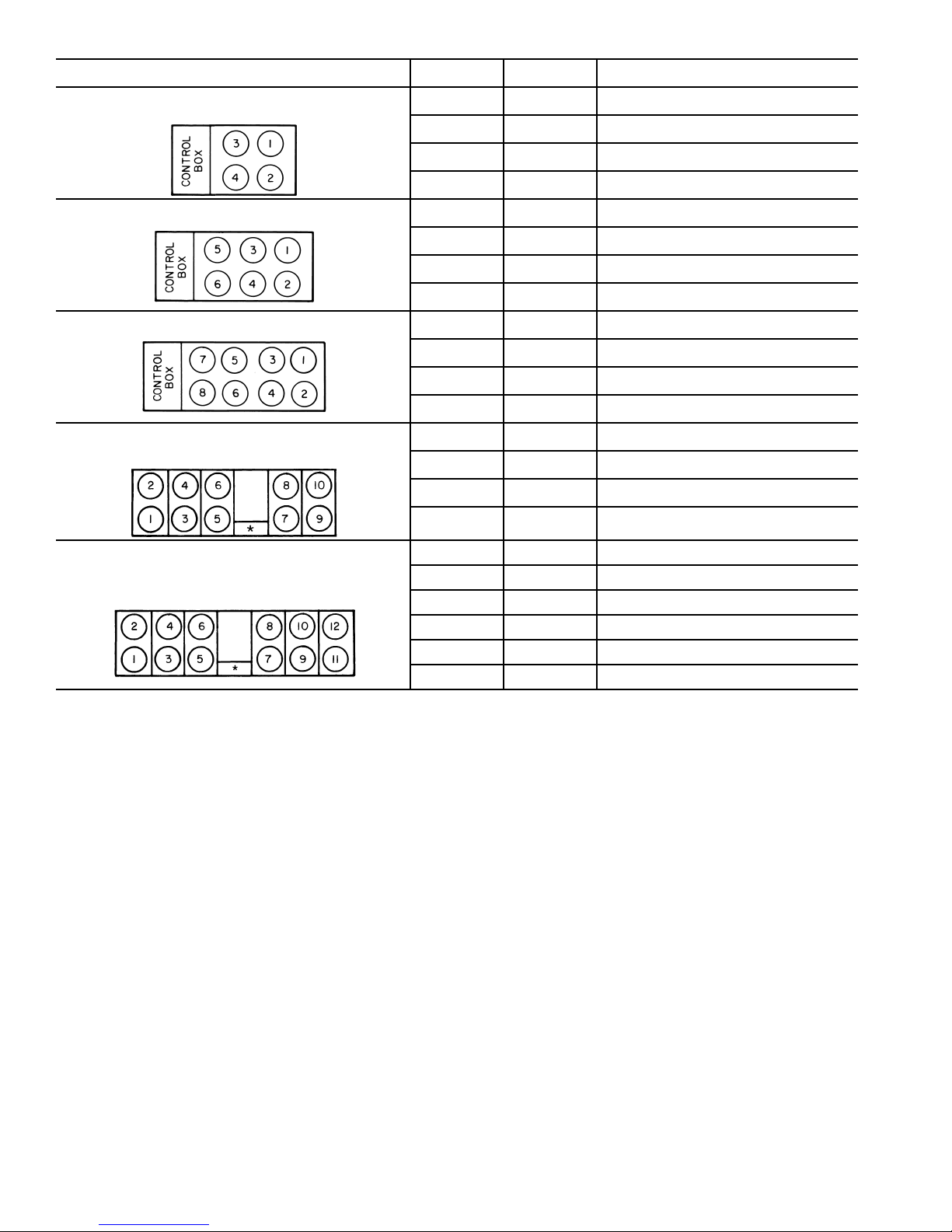
FAN ARRANGEMENT
30GTN,R040-050
30GUN,R040-050
30GTN,R060-090, 230B, 245B
30GUN,R060-090, 230B, 245B
30GTN,R100,110, 255B-315B
30GUN,R100,110, 255B-315B
30GTN,R130 (60 Hz),
30GUN,R130 (60 Hz)
POWER
FAN
NO.
1 — Compressor No. A1
2 — Compressor No. B1
3 1 First Stage of Condenser Fans
4 2 Second Stage of Condenser Fans
1 — Compressor No. A1
2 — Compressor No. B1
3, 4 1 First Stage of Condenser Fans
5, 6 2 Second Stage of Condenser Fans
1 — Compressor No. A1
2 — Compressor No. B1
3, 4 1 First Stage of Condenser Fans
5, 6, 7, 8 2 Second Stage of Condenser Fans
5, 7 — Compressor No. A1
6, 8 — Compressor No. B1
1, 2 1 First Stage of Condenser Fans
FAN RELAY NORMAL CONTROL
3, 4, 9, 10 2 Second Stage of Condenser Fans
30GTN,R130 (50 Hz), 150-210,
230A-315A, 330A/B-420A/B†
30GUN,R130 (50 Hz), 150-210,
230A-315A, 330A/B-420A/B†
*Control box.
†Fan numbers 11 and 12 do not apply to 30GTN,R and 30GUN,R 130-170 and associated modular units (see Table 1).
POWER
5, 7 — Compressor No. A1
6, 8 — Compressor No. B1
1, 11 1 First Stage of Condenser Fans, Circuit A
3, 9 2 Second Stage of Condenser Fans, Circuit A
2, 12 3 First Stage of Condenser Fans, Circuit B
4, 10 4 Second Stage of Condenser Fans, Circuit B
Fig. 18 — Condenser Fan Sequence
28
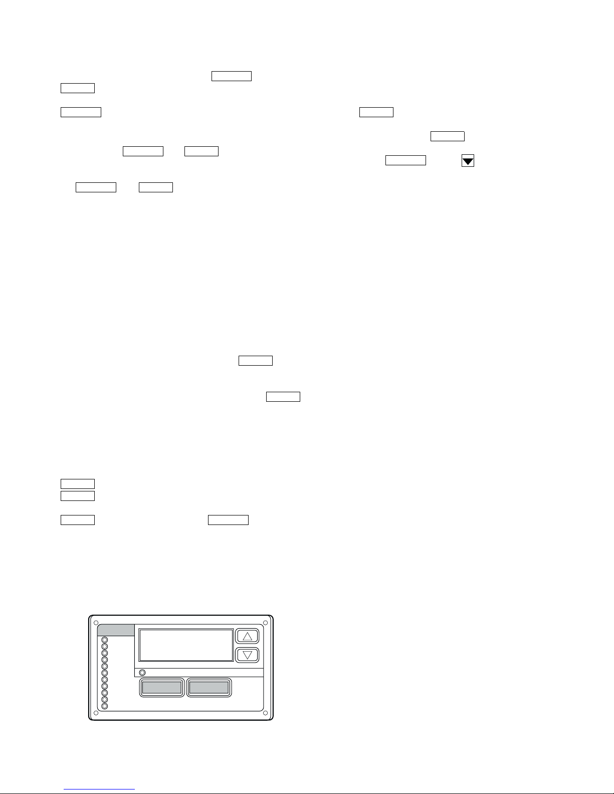
Marquee Display Usage (See Fig. 19 and
ENTER
Tables 7-25) —
user interface to the ComfortLink™ control system. The dis-
play has up and down arrow keys, an key, and an
ENTER
key. These keys are used to navigate through the dif-
ferent levels of the display structure. See Table 7. Press the
ESCAPE
key until the display is blank to move through the
top 11 mode levels indicated by LEDs on the left side of the
display .
Pressing the and keys simultaneously
will scroll a clear language text description across the display
indicating the full meaning of each display acronym. Pressing
the and keys when the display is blank
ESCAPE ENTER
(Mode LED level) will return the Marquee display to its default
menu of rotating display items. In addition, the password will
be disabled requiring that it be entered again before changes
can be made to password protected items.
Clear language descriptions in English, Spanish, French, or
Portuguese can be displayed when properly configuring the
LANG variable in the Configuration mode, under DISP submode. See Table 16.
NOTE: When the LANG variable is cha nged to 1, 2, or 3, all
appropriate display expansions will immediately change to the
new language. No power-off or control reset is required when
reconfiguring languages.
When a specific item is located, the display will flash showing the operator, the item, followed by the item value and then
followed by the item units (if any). Press the key to
stop the display at the item value. Items in the Configuration
and Service Test modes are password protected. The display
will flash PA SS and WORD when required. Use the
and arrow keys to enter the 4 digits of the password. The default password is 1111. The password can only be changed
through CCN devices such as ComfortWORKS® and Service
T ool.
Changing item values or testing outputs is accomplished in
the same manner. Locate and display the desired item. Press
ENTER
ENTER
to stop the display at the item value. Press the
key again so that the item value flashes . Use the ar-
row keys to change the value or state of an i tem and press t he
ENTER ESCAPE
key to accept it. Press the key and the
item, value, or units display will resume. Repeat the process as
required for other items.
See Tabl es 7-25 for further details.
Service Test (See Table 9) —
control cir cuit power must be on.
Run Status
Service Test
Temperature
Pressures
Setpoints
Inputs
Outputs
Configuration
Time Clock
Operating Modes
Alarms
Fig. 19 — Scrolling Marquee Display
The Marquee display module provides the
ESCAPE
ESCAPE ENTER
Both main power and
MODE
Alarm Status
ESCAPE
ENTER
ENTER
ENTER
The Service Test function should be used to verify proper
operation of compressors, unloaders, hot gas bypass (if installed), cooler pump and remote alarm relays, EXVs and condenser fans. To use the Service Test mode, the Enable/Off/
Remote Contact switch must be in the OFF position. Use the
display keys and Table 9 to enter the mode and display TEST.
Press twice so that OFF flashes. Enter the password if
required. Use either arrow key to change the TEST value to the
On position and press . Switch the Enable/Off/Re-
ENTER
mote Contact switch to the Enable position (Version 2.3 and
later). Press and the button to ent er the OUTS
ESCAPE
or COMP sub-mode.
Test the condenser fan, cooler pump, and alarm relays by
changing the item values from OFF to ON. These discrete outputs are turned off if there is no keypad activity for 10 minutes.
Use arrow keys to select desired percentage when testing expansion valves. When testing compressors, the lead compressor must be started first. All compressor outputs can be turned
on, but the control will limit the rate by staging one compressor
per minute. Compressor unloaders and hot gas bypass relays/
solenoids (if installed) can be tested with compressors on or
off. The relays under the COMP sub-mode will stay on for
10 minutes if there is no keypad activity. Compressors will stay
on until they are turned off by the operator. The Service Test
mode will remain enabled for as long as there is one or more
compressors running. All safeties are monitored during this test
and will turn a compressor, circuit or the machine off if required. Any other mode or sub-mode can be accessed, viewed,
or changed during the TEST mode. The MODE item (Run Status mode under sub-mode VIEW) will display “0” as long as
the Service mode is enabled. The TEST sub-mode value must
be changed back to OFF before the chiller can be switched to
Enable or Remote contact for normal operation.
Configuring and Operating Dual Chiller Control (See Table 18) —
able for the control of two units supplying chilled fluid on a
common loop. This control is designed for a parallel fluid flow
arrangement only. One chiller must be configured as the master
chiller, the other as the slave chiller. An additional leaving fluid
temperature thermistor (Dual Chiller LWT) must be installed
as shown in Fig. 20 and connected to the master chiller. See
Field Wiring section for Dual Chiller L WT sensor wiring.
To configure the two chillers for opera tion, follow the example shown in Table 18. The master chiller will be configured
with a slave chiller at address 6. Also in this example, the master chiller will be configured to use Lead/Lag Balance to even
out the chiller runtimes weekly. The Lag Start Delay feature
will be set to 10 minutes. The master and slave chillers cannot
have the same CCN address (CCNA, Configuration mode under OPT2). Both chillers must have the control method variable
(CTRL, Configuration mode under OPT2) set to ‘3.’ In addi-
tion, the chillers must both be connected together on the sam e
CCN bus. Connections can be made to the CCN screw terminals on TB3 in both chillers. The master chiller will determine
which chiller will be Lead and which will be Lag. The master
chiller controls the slave chiller by forcing the slave chiller’s
CCN START/STOP variable (CHIL_S_S), control point
(CTPT) and demand limit (DEM_LIM).
The master chiller is now configured for dual chiller operation. To configure the slave chiller, only the LLEN and MSSL
variables need to be set. Enable the Lead/ Lag chiller enable
variable (LLEN) as shown Table 18. Similarly, set the M aster/
Slave Select variable (MSSL) to SLVE. The variables LLBL,
LLBD, an LLDY are not used by the slave chiller.
Refer to Field Wiring section on page 67 for wiring
information.
The dual chiller routine is avail-
29
 Loading...