


 Loading...
19XR Positive Pressure Storage System 50/60 Hz
Installation, Operating, and
Maintenance Instructions
SAFETY CONSIDERATIONS
Positive pressure storage systems are designed to provide safe and reliable service when operated within design specifications. When operating this equipment, use good judgment and safety precautions to avoid damage to equipment and property or injury to personnel.
Installation, start-up, and servicing of this equipment can be hazardous due to system pressures, electrical components, and equipment location (roofs, elevated structures, etc.). Only trained, qualified installers and service technicians should install, start up, and service this equipment.
Be sure you understand and follow the procedures and safety precautions contained in this guide.
 DANGER
Failure to follow these procedures will result in severe personal injury or death.
DO NOT VENT refrigerant relief valves within a building. Outlet from rupture disc or relief valve must be vented outdoors in accordance with the latest edition of ASHRAE 15 (American Society of Heating, Refrigerating, and AirConditioning Engineers). The accumulation of refrigerant in an enclosed space can displace oxygen and cause asphyxiation.
PROVIDE adequate ventilation in accordance with ASHRAE 15, especially for enclosed and low overhead spaces. Inhalation of high concentrations of vapor is harmful and may cause heart irregularities, unconsciousness, or death. Misuse can be fatal. Vapor is heavier than air and reduces the amount of oxygen available for breathing. Product causes eye and skin irritation. Decomposition products are hazardous.
DO NOT USE OXYGEN to purge lines or to pressurize a machine for any purpose. Oxygen gas reacts violently with oil, grease, and other common substances.
NEVER EXCEED specified test pressures, VERIFY the allowable test pressure by checking the instruction literature and the design pressures on the equipment nameplate.
DO NOT USE air for leak testing. Use only tracer gases and dry nitrogen.
DO NOT VALVE OFF any safety device.
BE SURE that all pressure relief devices are properly installed and functioning before operating any machine.
 WARNING
Failure to follow these procedures may result in personal injury or death.
DO NOT USE TORCH to remove any component. System contains oil and refrigerant under pressure.
To remove a component, wear protective gloves and goggles and proceed as follows:
a.Shut off electrical power to unit.
b.Recover refrigerant to relieve all pressure from system using both high-pressure and low-pressure ports.
c.Traces of vapor should be displaced with nitrogen and the work area should be well ventilated. Refrigerant in contact with an open flame produces toxic gases.
d.Cut component connection tubing with tubing cutter, and remove component from unit. Use a pan to catch any oil that may come out of the lines and as a gage for how much oil to add to the system.
e.Carefully unsweat remaining tubing stubs when necessary. Oil can ignite when exposed to torch flame.
DO NOT USE eyebolts or eyebolt holes to rig machine sections or the entire assembly.
DO NOT work on high-voltage equipment unless you are a qualified electrician.
DO NOT WORK ON electrical components, including control panels, switches, starters, or oil heater until you are sure ALL POWER IS OFF and no residual voltage can leak from capacitors or solid-state components.
LOCK OPEN AND TAG electrical circuits during servicing. IF WORK IS INTERRUPTED, confirm that all circuits are de-energized before resuming work.
AVOID SPILLING liquid refrigerant on skin or getting it into the eyes. USE SAFETY GOGGLES. Wash any spills from the skin with soap and water. If any enters the eyes, IMMEDIATELY FLUSH EYES with water and consult a physician.
NEVER APPLY an open flame or live steam to a refrigerant cylinder. Dangerous overpressure can result. When necessary to heat refrigerant, use only warm (110°F [43°C]) water.
DO NOT REUSE disposable (nonreturnable) cylinders or attempt to refill them. It is DANGEROUS AND ILLEGAL. When cylinder is emptied, evacuate remaining gas pressure, loosen the collar and unscrew and discard the valve stem. DO NOT INCINERATE.
(Warnings continued on next page.)
Manufacturer reserves the right to discontinue, or change at any time, specifications or designs without notice and without incurring obligations.
Catalog No. 04-531900050-01 |
Printed in U.S.A. |
Form 19XR-CLT-16SI Rev. A |
Pg 1 |
8-19 |
Replaces: 19XR-6SI |

 WARNING
CHECK THE REFRIGERANT TYPE before transferring refrigerant to the machine. The introduction of the wrong refrigerant can cause damage or malfunction to this machine.
Operation of this equipment with refrigerants other than those cited herein should comply with ASHRAE 15 (latest edition). Contact Carrier for further information on use of this machine with other refrigerants.
ENSURE that refrigerant is only pumped to or stored in tanks that are ASME (American Society of Mechanical Engineers) certified for the pressures appropriate to the refrigerant being handled.
DO NOT ATTEMPT TO REMOVE fittings, covers, etc., while machine is under pressure or while machine is running. Be sure pressure is at 0 psig (0 kPa) before breaking any refrigerant connection.
CAREFULLY INSPECT all relief devices, rupture discs, and other relief devices AT LEAST ONCE A YEAR. If machine operates in a corrosive atmosphere, inspect the devices at more frequent intervals.
DO NOT ATTEMPT TO REPAIR OR RECONDITION any relief device when corrosion or build-up of foreign material (rust, dirt, scale, etc.) is found within the valve body or mechanism. Replace the device.
DO NOT install relief devices in series or backwards.
USE CARE when working near or in line with a compressed spring. Sudden release of the spring can cause it and objects in its path to act as projectiles.
 CAUTION
Failure to follow these procedures may result in personal injury or damage to equipment.
EQUIPMENT should be operated by certified personnel only.
DO NOT STEP on refrigerant lines. Broken lines can whip about and cause personal injury and damage to the machine.
DO NOT climb over a machine. Use platform, catwalk, or staging. Follow safe practices when using ladders.
USE MECHANICAL EQUIPMENT (crane, hoist, etc.) to lift or move inspection covers or other heavy components. Even if components are light, use such equipment when there is a risk of slipping or losing your balance.
BE AWARE that certain automatic start arrangements CAN ENGAGE THE STARTER. Open the disconnect ahead of the starter in addition to shutting off the machine or pump.
USE only repair or replacement parts that meet the code requirements of the original equipment.
DOUBLE-CHECK that coupling nut wrenches, dial indicators, or other items have been removed before rotating any shafts.
DO NOT LOOSEN a packing gland nut before checking that the nut has a positive thread engagement.
PERIODICALLY INSPECT all valves, fittings, and piping for corrosion, rust, leaks, or damage.
DO NOT MIX REFRIGERANT from chillers that use different compressor oils. Compressor damage can result.
DO NOT re-use compressor oil or any oil that has been exposed to the atmosphere. Dispose of oil per local codes and regulations.
DO NOT leave refrigerant system open to air any longer than the actual time required to service the equipment. Seal circuits being serviced and charge with dry nitrogen to prevent oil contamination when timely repairs cannot be completed.
CONTENTS
Page
SAFETY CONSIDERATIONS . . . . . . . . . . . . . . . . . . . 1 INTRODUCTION . . . . . . . . . . . . . . . . . . . . . . . . . . . . . 2 INSTALLATION . . . . . . . . . . . . . . . . . . . . . . . . . . . . . . 3 Step 1 — Complete Pre-Installation Checks . . . . . . 3
•IDENTIFY UNIT
•INSPECT SHIPMENT
Step 2 — Mount the Pumpout Unit . . . . . . . . . . . . . . 3
•MOUNTING ON THE CHILLER
•FLOOR MOUNTING
Step 3 — Rig the Storage Tank . . . . . . . . . . . . . . . . . 3
Step 4 — Make Piping Connections . . . . . . . . . . . . . 6
• INSTALL VENT PIPING TO RELIEF DEVICES
Step 5 — Make Electrical Connections . . . . . . . . . . 6 CONTROLS AND COMPONENTS . . . . . . . . . . . . . . 10 Pumpout Unit . . . . . . . . . . . . . . . . . . . . . . . . . . . . . . 10
•CONTROLS
•SAFETY CONTROL SETTINGS
•COMPRESSOR
•CONDENSER
•OIL SEPARATOR
•SUCTION AND DISCHARGE VALVES
Storage Tank . . . . . . . . . . . . . . . . . . . . . . . . . . . . . . 11
•DRAIN VALVE
•DUAL RELIEF VALVES
•PRESSURE GAGE
•LEVEL GAGE
OPERATION . . . . . . . . . . . . . . . . . . . . . . . . . . . . . . . 11
Overview . . . . . . . . . . . . . . . . . . . . . . . . . . . . . . . . . . 11
•REFRIGERANT TRANSFER
•TRANSFERRING LIQUID REFRIGERANT FROM THE CHILLER COOLER TO THE CHILLER CONDENSER OR PUMPOUT STORAGE TANK
•TRANSFERRING LIQUID REFRIGERANT FROM THE CHILLER CONDENSER OR PUMPOUT STORAGE TANK TO THE CHILLER COOLER
•DISTILLING THE REFRIGERANT
Pumpout and Refrigerant Transfer Procedures . . 12
•PREPARATION
•OPERATING THE OPTIONAL PUMPOUT UNIT (FIG. 9)
MAINTENANCE . . . . . . . . . . . . . . . . . . . . . . . . . . . . . 17
Storage Tank . . . . . . . . . . . . . . . . . . . . . . . . . . . . . . 17
Ordering Replacement Parts . . . . . . . . . . . . . . . . . . 17
TROUBLESHOOTING . . . . . . . . . . . . . . . . . . . . . . . . 17
INTRODUCTION
The 19XR Positive Pressure Storage (PPS) system has been designed to help owners and operators of positive pressure chillers store HFC-134a refrigerant during service and repair work. The 19XR system conserves this refrigerant and prevents the release of excessive amounts of refrigerant into the atmosphere. The proper use of this equipment minimizes the loss of HFCs.
The 19XR PPS system shown in Fig. 1 consists of a pump-out unit mounted on a storage tank. The pumpout unit is offered as a free-standing unit that can be used with chillers that have an existing storage tank or with chillers that have isolation valves that permit built-in refrigerant storage.
The 19XR PPS systems are factory tested and certified to the American Society of Mechanical Engineers (ASME) pres-sure vessel code. The tanks are constructed of certified steel and are pressure rated at 185 psig (1276 kPa). The PPS storage tank is equipped with dual relief valves for proper venting per ASHRAE 15 (American Society of Heating, Refrigerating, and Air-Condi- tioning Engineers) guidelines. An automatic level switch is prewired to the control circuit to ensure proper storage levels.
2
The 19XR pumpout unit is a complete, hermetic, compact unit that consists of:
•a hermetic compressor with a direct-drive motor.
•a water-cooled refrigerant condenser.
•an oil separator.
•suction and discharge valves to control refrigerant flow.
•prewired safety and control devices.
INSTALLATION
Step 1 — Complete Pre-Installation Checks
IDENTIFY UNIT
Identify the assembly number (see Table 1) printed on the pumpout unit and storage tank nameplates. Check this information against the job requirements. Figure 1 shows the PPS system and its major components. Refer to Tables 2 and 3 for physical data.
INSPECT SHIPMENT
Inspect unit for damage before removing unit from shipping conveyance. If unit appears damaged, it should be inspected by a ship-
ping inspector before removal. File a claim with the shipping company if shipment is damaged or incomplete. The manufacturer is not responsible for damage incurred during transit.
Check all components. Notify the supplier immediately if any item is missing. To prevent loss or damage, leave all parts in their original package until they are needed.
Step 2 — Mount the Pumpout Unit
The pumpout unit, if purchased separately, may be mounted directly on the chiller or it may be floor mounted.
MOUNTING ON THE CHILLER
See instructions provided with the chiller for mounting the pumpout unit. A typical chiller mount is shown in Fig. 2.
FLOOR MOUNTING
Select a ventilated and accessible area, free of traffic or other hazards. Remove and discard the 4 angle supports at the base of the pumpout unit and bolt the unit to the floor through the holes at the base of the pumpout unit. Special isolation is unnecessary. Contact surface and dimensions for the pumpout unit are given in Fig. 3.
Table 1 — Positive Pressure System Assembly Numbers (R-134a)
PUMPOUT |
|
|
|
|
|
|
SYSTEM |
PUMPOUT UNIT |
COMPRESSOR MOTOR |
MAXIMUM |
LRA |
STORAGE TANK |
|
ARRANGEMENT |
ASSEMBLY NUMBER |
(V-PH-Hz) |
RLA |
|||
|
|
|||||
NUMBER |
|
|
|
|
|
|
19XR04027401 |
19XR04035801 |
208/230-3-50/60 |
15.8 |
105.0 |
28 cu ft (0.8 cu m) |
|
19XR04027402 |
19XR04035802 |
460-3-60 |
7.8 |
52.0 |
28 cu ft (0.8 cu m) |
|
19XR04027403 |
19XR04035803 |
400-3-50 |
7.8 |
52.0 |
28 cu ft (0.8 cu m) |
|
19XR04027501 |
19XR04035801 |
208/230-3-50/60 |
15.8 |
105.0 |
52 cu ft (1.5 cu m) |
|
19XR04027502 |
19XR04035802 |
460-3-60 |
7.8 |
52.0 |
52 cu ft (1.5 cu m) |
|
19XR04027503 |
19XR04035803 |
400-3-50 |
7.8 |
52.0 |
52 cu ft (1.5 cu m) |
|
19XR04026801 |
19XR04035801 |
208/230-3-50/60 |
15.8 |
105.0 |
Free-standing |
|
19XR04026802 |
19XR04035802 |
460-3-60 |
7.8 |
52.0 |
Free-standing |
|
19XR04026803 |
19XR04035803 |
400-3-50 |
7.8 |
52.0 |
Free-standing |
|
19XR14017801 |
19XR04035801 |
208/230-3-50/60 |
15.8 |
105.0 |
Unit-mounted, frame 1 |
|
19XR14017802 |
19XR04035802 |
460-3-60 |
7.8 |
52.0 |
Unit-mounted, frame 1 |
|
19XR14017803 |
19XR04035803 |
400-3-50 |
7.8 |
52.0 |
Unit-mounted, frame 1 |
|
19XR34017801 |
19XR04035801 |
208/230-3-50/60 |
15.8 |
105.0 |
Unit-mounted, frame 2 or 3 |
|
19XR34017802 |
19XR04035802 |
460-3-60 |
7.8 |
52.0 |
Unit-mounted, frame 2 or 3 |
|
19XR34017803 |
19XR04035803 |
400-3-50 |
7.8 |
52.0 |
Unit-mounted, frame 2 or 3 |
|
19XR44017801 |
19XR04035801 |
208/230-3-50/60 |
15.8 |
105.0 |
Unit-mounted, frame 4 |
|
19XR44017802 |
19XR04035802 |
460-3-60 |
7.8 |
52.0 |
Unit-mounted, frame 4 |
|
19XR44017803 |
19XR04035803 |
400-3-50 |
7.8 |
52.0 |
Unit-mounted, frame 4 |
|
19XR54017801 |
19XR04035801 |
208/230-3-50/60 |
15.8 |
105.0 |
Unit-mounted, frame 5 |
|
19XR54017802 |
19XR04035803 |
460-3-60 |
7.8 |
52.0 |
Unit-mounted, frame 5 |
|
19XR54017803 |
19XR04035803 |
400-3-50 |
7.8 |
52.0 |
Unit-mounted, frame 5 |
|
19XR64017801 |
19XR04035801 |
208/230-3-50/60 |
15.8 |
105.0 |
Unit-mounted, frame 6 |
|
19XR64017802 |
19XR04035802 |
460-3-60 |
7.8 |
52.0 |
Unit-mounted, frame 6 |
|
19XR64017803 |
19XR04035803 |
400-3-50 |
7.8 |
52.0 |
Unit-mounted, frame 6 |
|
19XR74017801 |
19XR04035801 |
208/230-3-50/60 |
15.8 |
105.0 |
Unit-mounted, frame 7 |
|
19XR74017802 |
19XR04035802 |
460-3-60 |
7.8 |
52.0 |
Unit-mounted, frame 7 |
|
19XR74017803 |
19XR04035803 |
400-3-50 |
7.8 |
52.0 |
Unit-mounted, frame 7 |
|
19XR84017801 |
19XR04035801 |
208/230-3-50/60 |
15.8 |
105.0 |
Unit-mounted, frame 8 |
|
19XR84017802 |
19XR04035802 |
460-3-60 |
7.8 |
52.0 |
Unit-mounted, frame 8 |
|
19XR84017803 |
19XR04035803 |
400-3-50 |
7.8 |
52.0 |
Unit-mounted, frame 8 |
LEGEND
LRA — Locked Rotor Amps
RLA — Rated Load Amps
NOTES:
1.All storage vessels are 185 psig (1276 kPa) designs per the ASME (American Society of Mechanical Engineers) Boiler Pressure Vessel Code, Section VIII Division 1.
2.All units above are shipped with a 15 psig (103 kPa) nitrogen charge.
3.Nominal horsepower for all pumpout units is 3.0.
3

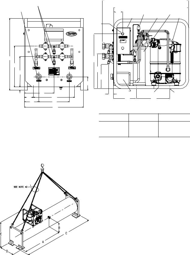
Step 3 — Rig the Storage Tank
The complete 19XR system can be rigged as a single assembly. See the rigging instructions on the label attached to the assembly. Also refer to the rigging guide (Fig. 4), physical data in Tables 2 and 3, and contact surface and dimensions for the complete system in Fig. 5. Lift the assembly only from the 4 points indicated in the rigging guide. Each rigging cable must be capable of supporting the entire weight of the assembly.
FRAME
ASSEMBLY
CONTROL
PANEL
 WARNING
Lifting the assembly from points other than those specified may result in serious damage to the assembly and personal injury. Rigging equipment and procedures must be adequate for assembly. See Tables 2 and 3 for weights. (These weights are broken down into pumpout unit and storage tank weights. For the complete assembly weight, add all components together.)
|
TERMINAL |
SWITCH |
CONTACTOR |
STRIP |
FUSES |
|
VALVE 2 |
|
|
|
|
VALVE 3 |
|
|
COMPRESSOR |
|
|
|
|
|
|
VALVE 4 |
|
|
|
|
VALVE 5 |
|
|
|
|
a19-2444ENTERING |
|
OIL |
|
TRANSFORMER |
WATER |
|
|
|
|
|
HEATER |
a19-2444 |
a19-1569ef |
|
LEAVING |
|
|||
|
|
|
|
|
|
OIL |
|
|
|
WATER |
SEPARATOR |
|
|
|
CONDENSER |
|
|
|
19XR PUMPOUT UNIT |
19XR CONTROL BOX (INTERIOR) |
Fig. 1 — 19XR Positive Pressure Storage System
COMPRESSOR
CONTROL
BOX
VALVE
ASSEMBLY
CONDENSER
a19-1570ef
OIL
SEPARATOR
Fig. 2 — 19XR Pumpout Unit: Typical Chiller Mount
4
|
|
|
|
|
|
|
|
28.45 |
|
|
|
|
|
|
|
|
|
|
|
|
|
|
|
|
|
|
|
||
|
|
|
|
|
|
|
(723) |
|
|
|
|
|
||
VAPOR CONNECTIONS |
|
|
|
|
|
|
|
24.75 |
|
|
|
|||
|
|
|
|
|
|
|
|
|
|
|||||
|
1/2" MALE FLARE |
|
|
|
|
|
|
|
|
|
|
|||
|
|
|
|
|
|
|
|
|
|
|
||||
|
|
|
|
|
|
|
(629) |
|
|
|
||||
WATER CONNECTIONS |
|
|
3.25 |
|
|
|
|
|
||||||
|
|
HIGH-PRESSURE SWITCH |
OIL SEPARATOR |
|||||||||||
|
||||||||||||||
3/4" FNPT |
(83) |
|||||||||||||
CONTROL PANEL |
|
VACUUM SWITCH |
COMPRESSOR |
|||||||||||
|
|
|
|
|
|
|
|
|||||||
|
|
ELECTRICAL |
|
|
|
|
CONNECTION |
|
|
|
|
LOCATION |
|
|
23.00 |
|
18.13 |
|
|
(584) |
|
(461) |
|
|
|
|
|
|
|
13.12 |
|
|
|
|
(333) |
|
11.59 |
|
|
|
|
|
|
|
9.74 |
|
(294) |
|
|
|
|
|
|
|
(247) |
|
8.21 |
|
|
|
|
|
|
|
|
|
(209) |
|
|
|
|
4.25 |
|
|
|
|
(108) |
|
|
1.00 (25) |
|
|
|
|
9.50 |
|
CONDENSER |
|
MOUNTING HOLES |
|
(2X) 1.82 |
OIL SIGHTGLASS |
||
(241) |
|
(33) |
|
|
2.88 |
13.25 |
|
|
|
7.94 |
10.50 |
|
||
(73) |
(337) |
|
||
4.58 |
9.48 |
(202) |
(267) |
|
(116) |
(250) |
|
|
|
|
19.00 |
ELECTRICAL CONNECTION OPTION LIST |
||
|
(438) |
|||
|
|
|
|
|
NOTE: Dimensions in inches (millimeters). |
TRADE SIZE |
QTY |
LOCATION |
|
(in.) |
||
|
|
|
a19-2445 |
1/2 |
1 |
TOP |
|
3/4 |
1 |
BOTTOM |
|
1 |
1 |
MIDDLE |
|
11/4 |
1 |
MIDDLE |
Fig. 3 — Pumpout Unit Contact Surfaces and Dimensions
a19-1572ef
NOTES:
1. Each chain must be capable of supporting the entire weight of the machine.
2. Minimum chain length: |
|
|
|
|
|
|
|
||
28 ft3 (0.79 m3) tank — 10 -0 (3098 mm) |
|
|
|
|
|
||||
52 ft3 (1.47 m3) tank — 15 -6 (4724 mm) |
|
|
|
|
|
||||
|
|
|
|
|
|
|
|
|
|
|
CENTER OF |
|
|
|
|
|
|
||
STORAGE |
GRAVITY |
OVERALL DIMENSIONS |
EMPTY |
||||||
DIMENSIONS |
|
(APPROX.) |
|
||||||
TANK |
|
|
WEIGHT |
||||||
(APPROX.) |
|
ft-in. (mm) |
|
||||||
SIZE |
|
|
lb (kg) |
||||||
ft-in. (mm) |
|
|
|
|
|
||||
|
|
|
|
|
|
|
|||
|
A |
|
B |
C |
|
D |
|
E |
|
28 CU FT |
4-91/8 |
|
1-77/8 |
10-5 |
|
2-43/4 |
|
4-41/4 |
2,385 |
(0.8 CU M) |
(1451) |
|
(505) |
(3175) |
|
(730) |
|
(1327) |
(1082) |
52 CU FT |
6-115/8 |
|
1-83/4 |
14-111/4 |
|
2-81/2 |
|
4-81/4 |
3,415 |
(1.5 CU M) |
(2124) |
|
(527) |
(4553) |
|
(826) |
|
(1429) |
(1549) |
Fig. 4 — Rigging Guide
5

Table 2 — Physical Data — 19XR Pumpout Unit
|
|
ENGLISH |
SI |
Pumpout Unit Weight* |
lb (kg) |
164 |
(75) |
Pumpout Condenser Water Flow Rate |
gpm (L/s) |
7-9 |
(.45-.58) |
Pumpout Condenser Water Pressure Drop |
psig (kPa) |
0.3 |
(2.0) |
Maximum Entering Condenser Water Temperature |
F (C) |
85 |
(29) |
Maximum Leaving Condenser Water Temperature |
F (C) |
100 |
(37) |
Relief Valve |
psig (kPa) |
235 |
(1620) |
Condenser Pressure Rating |
|
|
|
Refrigerant Side |
psig (kPa) |
450 |
(3102) |
Waterside |
psig (kPa) |
450 |
(3102) |
*The pumpout unit weight includes the compressor/condenser, control box, and the oil separator.
NOTES:
1. The motor is hermetic with thermal protection.
2.The control box is mounted and wired with an ON/OFF/AUTO. switch according to NEMA 1 (National Electrical Manufacturing Association).
3.The starter contactor is located in the control box. The overloads on the motor are wired and the internal disconnect switch is supplied by the customer.
Table 3 — 19XR Storage Tank Rated Dry Weight and Refrigerant Capacity
|
SIZE |
|
TANK OD |
|
DRY WEIGHT* |
MAXIMUM REFRIGERANT CAPACITY LB (KG) |
|
|
|
|
ASHRAE/ANSI 15 |
UL 1963 |
|||
|
cu ft (cu m) |
|
in. (mm) |
|
lb (kg) |
||
|
|
|
R-134a |
R-134a |
|||
|
|
|
|
|
|
||
|
28 (0.8) |
|
24.00 (610) |
|
2334 (1059) |
1860 (844) |
1716 (778) |
|
52 (1.5) |
|
27.25 (692) |
|
3414 (1549) |
3563 (1616) |
3286 (1491) |
|
|
LEGEND |
|
|
|
||
ANSI |
— American National Standards Institute |
|
|
|
|||
ASHRAE — American Society of Heating, Refrigeration, |
|
|
|
||||
|
and Air-Conditioning Engineers |
|
|
|
|||
UL |
— Underwriters’ Laboratories |
|
|
|
|||
*The above dry weight includes the pumpout unit weight of 164 lb (75 kg).
Step 4 — Make Piping Connections
Figure 5 represents typical pumpout unit/chiller piping connections. Standard connections for 1/2-in. OD copper tubing are provided. Install the field-supplied FPT tee with pipe plug in the piping as shown in Fig. 5. This tee is used for refrigerant charging.
NOTE: If any field piping runs exceed 50 ft in length, use 7/8-in. OD copper tubing to minimize pressure drop.
Pumpout unit water piping connections are shown in Fig. 5. Both connections are 3/4-in. NPT (female). A shutoff valve should be installed in the water line. Provide a means for blowing water from the condenser coil at winter shutdown to prevent freeze-up damage. Refer to the Job Data for water piping particulars.
INSTALL VENT PIPING TO RELIEF DEVICES
The pumpout storage tank is factory-equipped with relief devices. Refer to Fig. 6 and Table 4 for size and location of the relief devices. Vent the relief devices to the outdoors in accordance with ANSI/ASHRAE 15 Safety Code (latest edition) for Mechanical Refrigeration and all other applicable codes. Pumpout unit relief devices are set to relieve at 235 psig (1620 kPa). Storage tank relief devices are set to relieve at 185 psig (1276 kPa).
 DANGER
Refrigerant discharged into confined spaces can displace oxygen and cause asphyxiation.
1.If relief devices are manifolded, the cross-sectional area of the relief pipe must at least equal the sum of the areas required for individual relief pipes.
2.Provide a pipe plug near outlet side of each relief device for leak testing. Provide pipe fittings that allow vent piping to be disconnected periodically for inspection of valve mechanism.
3.Piping to relief devices must not apply stress to the device. Adequately support piping. A length of flexible tubing or piping near the device is essential on spring-isolated machines.
4.Cover the outdoor vent with a rain cap and place a condensation drain at the low point in the vent piping to prevent water build-up on the atmospheric side of the relief device.
Step 5 — Make Electrical Connections
See nameplate on compressor of pumpout unit and Table 1 for motor electrical data. Wire unit according to the diagram inside the control box.
Figure 7 is the wiring schematic for a complete system that includes the 19XR storage tank and the pumpout unit. Figure 8 is the wiring schematic for the pumpout unit. Use this schematic for installations that do not include an auxiliary pumpout storage tank.
NOTE: Use copper conductors only.
6
Loading...