


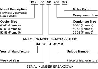
19XL Hermetic Centrifugal Liquid Chillers
50/60 Hz
With HCFC-22 and HFC-134a
Start-Up, Operation, and Maintenance Instructions
SAFETY CONSIDERATIONS
Centrifugal liquid chillers are designed to provide safe and reliable service when operated within design speci®cations. When operating this equipment, use good judgment and safety precautions to avoid damage to equipment and property or injury to personnel.
Be sure you understand and follow the procedures and safety precautions contained in the chiller instructions as well as those listed in this guide.
DO NOT VENT refrigerant relief valves within a building. Outlet from rupture disc or relief valve must be vented outdoors in accordance with the latest edition of ANSI/ASHRAE 15 (American National Standards Institute/American Society of Heating, Refrigeration, and Air Conditioning Engineers). The accumulation of refrigerant in an enclosed space can displace oxygen and cause asphyxiation.
PROVIDE adequate ventilation in accordance with ANSI/ASHRAE 15, especially for enclosed and low overhead spaces. Inhalation of high concentrations of vapor is harmful and may cause heart irregularities, unconsciousness, or death. Misuse can be fatal. Vapor is heavier than air and reduces the amount of oxygen available for breathing. Product causes eye and skin irritation. Decomposition products are hazardous.
DO NOT USE OXYGEN to purge lines or to pressurize a chiller for any purpose. Oxygen gas reacts violently with oil, grease, and other common substances.
NEVER EXCEED speci®ed test pressures, VERIFY the allowable test pressure by checking the instruction literature and the design pressures on the equipment nameplate.
DO NOT USE air for leak testing. Use only refrigerant or dry nitrogen.
DO NOT VALVE OFF any safety device.
BE SURE that all pressure relief devices are properly installed and functioning before operating any chiller.
DO NOT WELD OR FLAMECUT any refrigerant line or vessel until all refrigerant (liquid and vapor) has been removed from chiller. Traces of vapor should be displaced with dry air or nitrogen and the work area should be well ventilated. Refrigerant in contact with an open ¯ame produces toxic gases.
DO NOT USE eyebolts or eyebolt holes to rig chiller sections or the entire assembly.
DO NOT work on high-voltage equipment unless you are a quali- ®ed electrician.
DO NOT WORK ON electrical components, including control panels, switches, starters, or oil heater until you are sure ALL POWER IS OFF and no residual voltage can leak from capacitors or solidstate components.
LOCK OPEN AND TAG electrical circuits during servicing. IF WORK IS INTERRUPTED, con®rm that all circuits are deenergized before resuming work.
AVOID SPILLING liquid refrigerant on skin or getting it into the eyes. USE SAFETY GOGGLES. Wash any spills from the skin with soap and water. If liquid refrigerant enters the eyes, IMMEDIATELY FLUSH EYES with water and consult a physician.
NEVER APPLY an open ¯ame or live steam to a refrigerant cylinder. Dangerous over pressure can result. When it is necessary to heat refrigerant, use only warm (110 F [43 C]) water.
DO NOT REUSE disposable (nonreturnable) cylinders or attempt to re®ll them. It is DANGEROUS AND ILLEGAL. When cylinder is emptied, evacuate remaining gas pressure, loosen the collar and unscrew and discard the valve stem. DO NOT INCINERATE.
CHECK THE REFRIGERANT TYPE before adding refrigerant to the chiller. The introduction of the wrong refrigerant can cause damage or malfunction to this chiller.
Operation of this equipment with refrigerants other than those cited herein should comply with ANSI/ASHRAE-15 (latest edition). Contact Carrier for further information on use of this chiller with other refrigerants.
DO NOT ATTEMPT TO REMOVE ®ttings, covers, etc., while chiller is under pressure or while chiller is running. Be sure pressure is at 0 psig (0 kPa) before breaking any refrigerant connection.
CAREFULLY INSPECT all relief devices, rupture discs, and other relief devices AT LEAST ONCE A YEAR. If chiller operates in a corrosive atmosphere, inspect the devices at more frequent intervals.
DO NOT ATTEMPT TO REPAIR OR RECONDITION any relief device when corrosion or build-up of foreign material (rust, dirt, scale, etc.) is found within the valve body or mechanism. Replace the device.
DO NOT install relief devices in series or backwards.
USE CARE when working near or in line with a compressed spring. Sudden release of the spring can cause it and objects in its path to act as projectiles.
DO NOT STEP on refrigerant lines. Broken lines can whip about and release refrigerant, causing personal injury.
DO NOT climb over a chiller. Use platform, catwalk, or staging. Follow safe practices when using ladders.
USE MECHANICAL EQUIPMENT (crane, hoist, etc.) to lift or move inspection covers or other heavy components. Even if components are light, use mechanical equipment when there is a risk of slipping or losing your balance.
BE AWARE that certain automatic start arrangements CAN ENGAGE THE STARTER, TOWER FAN, OR PUMPS. Open the disconnect ahead of the starter, tower fans, or pumps.
USE only repair or replacement parts that meet the code requirements of the original equipment.
DO NOT VENT OR DRAIN waterboxes containing industrial brines, liquid, gases, or semisolids without the permission of your process control group.
DO NOT LOOSEN waterbox cover bolts until the waterbox has been completely drained.
DOUBLE-CHECK that coupling nut wrenches, dial indicators, or other items have been removed before rotating any shafts.
DO NOT LOOSEN a packing gland nut before checking that the nut has a positive thread engagement.
PERIODICALLY INSPECT all valves, ®ttings, and piping for corrosion, rust, leaks, or damage.
PROVIDE A DRAIN connection in the vent line near each pressure relief device to prevent a build-up of condensate or rain water.
Manufacturer reserves the right to discontinue, or change at any time, speci®cations or designs without notice and without incurring obligations.
Book |
2 |
|
PC 211 |
Catalog No. 531-971 |
Printed in U.S.A. |
Form 19XL-4SS |
Pg 1 |
7-96 |
Replaces: 19XL-3SS |
Tab |
5a |
|
|
|
|
|
|
|
|
|
|
|
|
|
|
|
|
|
|
CONTENTS
Page
SAFETY CONSIDERATIONS . . . . . . . . . . . . . . . . . . . 1
INTRODUCTION . . . . . . . . . . . . . . . . . . . . . . . . . . . . . . 4
ABBREVIATIONS AND EXPLANATIONS . . . . . . . 4
CHILLER FAMILIARIZATION . . . . . . . . . . . . . . . . . . 5
Chiller Information Plate . . . . . . . . . . . . . . . . . . . . . . 5
System Components . . . . . . . . . . . . . . . . . . . . . . . . . 5
Cooler . . . . . . . . . . . . . . . . . . . . . . . . . . . . . . . . . . . . . . . 5
Condenser . . . . . . . . . . . . . . . . . . . . . . . . . . . . . . . . . . . 5
Motor-Compressor . . . . . . . . . . . . . . . . . . . . . . . . . . . 5
Control Center . . . . . . . . . . . . . . . . . . . . . . . . . . . . . . . 5
Factory-Mounted Starter (Optional) . . . . . . . . . . . . 5
Storage Vessel (Optional) . . . . . . . . . . . . . . . . . . . . . 5
REFRIGERATION CYCLE . . . . . . . . . . . . . . . . . . . . . 5
MOTOR/OIL REFRIGERATION
COOLING CYCLE . . . . . . . . . . . . . . . . . . . . . . . . . . . 5-8
LUBRICATION CYCLE . . . . . . . . . . . . . . . . . . . . . . . 8,9
Summary . . . . . . . . . . . . . . . . . . . . . . . . . . . . . . . . . . . . 8
Details . . . . . . . . . . . . . . . . . . . . . . . . . . . . . . . . . . . . . . 8
Oil Reclaim System . . . . . . . . . . . . . . . . . . . . . . . . . . 9
·DURING NORMAL CHILLER OPERATION
·DURING LIGHT LOAD CONDITIONS
STARTING EQUIPMENT . . . . . . . . . . . . . . . . . . . . 10,11
Unit Mounted Solid-State Starter
(Optional) . . . . . . . . . . . . . . . . . . . . . . . . . . . . . . . . . . 10
Unit Mounted Wye-Delta Starter
(Optional) . . . . . . . . . . . . . . . . . . . . . . . . . . . . . . . . . . 11
CONTROLS . . . . . . . . . . . . . . . . . . . . . . . . . . . . . . . 11-39 De®nitions . . . . . . . . . . . . . . . . . . . . . . . . . . . . . . . . . . 11
·ANALOG SIGNAL
·DIGITAL SIGNAL
·VOLATILE MEMORY
General . . . . . . . . . . . . . . . . . . . . . . . . . . . . . . . . . . . . . 11
PIC System Components . . . . . . . . . . . . . . . . . . . . 11
·PROCESSOR MODULE (PSIO)
·STARTER MANAGEMENT MODULE (SMM)
·LOCAL INTERFACE DEVICE (LID)
·6-PACK RELAY BOARD
·8-INPUT MODULES
·OIL HEATER CONTACTOR (1C)
·OIL PUMP CONTACTOR (2C)
·HOT GAS BYPASS CONTACTOR RELAY (3C) (Optional)
·CONTROL TRANSFORMERS (T1-T4)
·CONTROL AND OIL HEATER VOLTAGE SELECTOR (S1)
LID Operation and Menus . . . . . . . . . . . . . . . . . . . 14
·GENERAL
·ALARMS AND ALERTS
·MENU STRUCTURE
·TO VIEW POINT STATUS
·OVERRIDE OPERATIONS
·TIME SCHEDULE OPERATION
·TO VIEW AND CHANGE SET POINTS
·SERVICE OPERATION
PIC System Functions . . . . . . . . . . . . . . . . . . . . . . . 28
·CAPACITY CONTROL
·ENTERING CHILLED WATER CONTROL
·DEADBAND
·PROPORTIONAL BANDS AND GAIN
·DEMAND LIMITING
·CHILLER TIMERS
·OCCUPANCY SCHEDULE
Safety Controls . . . . . . . . . . . . . . . . . . . . . . . . . . . . . 29
· SHUNT TRIP
Default Screen Freeze . . . . . . . . . . . . . . . . . . . . . . . 29
Page
Motor Cooling Control . . . . . . . . . . . . . . . . . . . . . . . 29
Ramp Loading Control . . . . . . . . . . . . . . . . . . . . . . 31
Capacity Override . . . . . . . . . . . . . . . . . . . . . . . . . . . 31
High Discharge Temperature Control . . . . . . . . . 32
Oil Sump Temperature Control . . . . . . . . . . . . . . . 32
·PSIO SOFTWARE VERSIONS 08 AND LOWER
·PSIO SOFTWARE VERSIONS 09 AND HIGHER
Oil Cooler . . . . . . . . . . . . . . . . . . . . . . . . . . . . . . . . . . 32
Remote Start/Stop Controls . . . . . . . . . . . . . . . . . . 32
Spare Safety Inputs . . . . . . . . . . . . . . . . . . . . . . . . . 32
· SPARE ALARM CONTACTS
Condenser Pump Control . . . . . . . . . . . . . . . . . . . . 32
Condenser Freeze Protection . . . . . . . . . . . . . . . . 32
Tower Fan Relay . . . . . . . . . . . . . . . . . . . . . . . . . . . . 33
Auto. Restart After Power Failure . . . . . . . . . . . . 33
Water/Brine Reset . . . . . . . . . . . . . . . . . . . . . . . . . . . 33
·RESET TYPE 1
·RESET TYPE 2
·RESET TYPE 3
Demand Limit Control, Option
(Requires Optional 8-Input Module) . . . . . . . . . . 33
Surge Prevention Algorithm . . . . . . . . . . . . . . . . . 33
Surge Protection . . . . . . . . . . . . . . . . . . . . . . . . . . . . 34
Lead/Lag Control . . . . . . . . . . . . . . . . . . . . . . . . . . . 34
·COMMON POINT SENSOR INSTALLATION
·CHILLER COMMUNICATION WIRING
·LEAD/LAG OPERATION
·FAULTED CHILLER OPERATION
·LOAD BALANCING
·AUTO. RESTART AFTER POWER FAILURE
Ice Build Control . . . . . . . . . . . . . . . . . . . . . . . . . . . . 36
·ICE BUILD INITIATION
·START-UP/RECYCLE OPERATION
·TEMPERATURE CONTROL DURING ICE BUILD
·TERMINATION OF ICE BUILD
·RETURN TO NON-ICE BUILD OPERATIONS
Attach to Network Device Control . . . . . . . . . . . . 37
·CHANGING REFRIGERANT TYPES
·ATTACHING TO OTHER CCN MODULES
Service Operation . . . . . . . . . . . . . . . . . . . . . . . . . . . 38
·TO LOG ON
·TO LOG OFF
·HOLIDAY SCHEDULING
START-UP/SHUTDOWN/RECYCLE
SEQUENCE . . . . . . . . . . . . . . . . . . . . . . . . . . . . . . . 39-41
Local Start-Up . . . . . . . . . . . . . . . . . . . . . . . . . . . . . . 39
Shutdown Sequence . . . . . . . . . . . . . . . . . . . . . . . . 40
Automatic Soft-Stop Amps Threshold
(PSIO Software Version 09 and Higher) . . . . . . 40
Chilled Water Recycle Mode . . . . . . . . . . . . . . . . . 40
Safety Shutdown . . . . . . . . . . . . . . . . . . . . . . . . . . . . 41
BEFORE INITIAL START-UP . . . . . . . . . . . . . . . . 41-54
Job Data Required . . . . . . . . . . . . . . . . . . . . . . . . . . 41
Equipment Required . . . . . . . . . . . . . . . . . . . . . . . . 41
Using the Optional Storage Tank
and Pumpout System . . . . . . . . . . . . . . . . . . . . . . . 41
Remove Shipping Packaging . . . . . . . . . . . . . . . . 41
Open Oil Circuit Valves . . . . . . . . . . . . . . . . . . . . . . 41
Tighten All Gasketed Joints and
Guide Vane Shaft Packing . . . . . . . . . . . . . . . . . . 41
Check Chiller Tightness . . . . . . . . . . . . . . . . . . . . . 41
Refrigerant Tracer . . . . . . . . . . . . . . . . . . . . . . . . . . . 41
Leak Test Chiller . . . . . . . . . . . . . . . . . . . . . . . . . . . . 41
Standing Vacuum Test . . . . . . . . . . . . . . . . . . . . . . 43
Chiller Dehydration . . . . . . . . . . . . . . . . . . . . . . . . . 47
Inspect Water Piping . . . . . . . . . . . . . . . . . . . . . . . . 47
2
CONTENTS (cont)
Page
Check Optional Pumpout Compressor
Water Piping . . . . . . . . . . . . . . . . . . . . . . . . . . . . . . . 47
Check Relief Devices . . . . . . . . . . . . . . . . . . . . . . . . 47
Inspect Wiring . . . . . . . . . . . . . . . . . . . . . . . . . . . . . . 47
Carrier Comfort Network Interface . . . . . . . . . . . 48
Check Starter . . . . . . . . . . . . . . . . . . . . . . . . . . . . . . . 48
·MECHANICAL-TYPE STARTERS
·BENSHAW, INC. SOLID-STATE STARTER
Oil Charge . . . . . . . . . . . . . . . . . . . . . . . . . . . . . . . . . . |
50 |
Power Up the Controls and |
|
Check the Oil Heater . . . . . . . . . . . . . . . . . . . . . . . . |
50 |
· SOFTWARE VERSION |
|
Set Up Chiller Control Con®guration . . . . . . . . . |
50 |
Input the Design Set Points . . . . . . . . . . . . . . . . . . |
50 |
Input the Local Occupied Schedule |
|
(OCCPC01S) . . . . . . . . . . . . . . . . . . . . . . . . . . . . . . . |
50 |
Selecting Refrigerant Type . . . . . . . . . . . . . . . . . . . |
50 |
· TO CONFIRM REFRIGERANT TYPE |
|
· TO CHANGE REFRIGERANT TYPE |
|
Input Service Con®gurations . . . . . . . . . . . . . . . . 50
·PASSWORD
·INPUT TIME AND DATE
·CHANGE LID CONFIGURATION IF NECESSARY
·MODIFY CONTROLLER IDENTIFICATION IF NECESSARY
·INPUT EQUIPMENT SERVICE PARAMETERS IF NECESSARY
·MODIFY EQUIPMENT CONFIGURATION IF NECESSARY
·CHECK VOLTAGE SUPPLY
·PERFORM AN AUTOMATED CONTROL TEST
Check Optional Pumpout System
Controls and Compressor . . . . . . . . . . . . . . . . . . . 52
High Altitude Locations . . . . . . . . . . . . . . . . . . . . . 53
Charge Refrigerant Into Chiller . . . . . . . . . . . . . . . 53
·19XL CHILLER EQUALIZATION WITHOUT PUMPOUT UNIT
·19XL CHILLER EQUALIZATION WITH PUMPOUT UNIT
·TRIMMING REFRIGERANT CHARGE
INITIAL START-UP . . . . . . . . . . . . . . . . . . . . . . . . . 55,56 Preparation . . . . . . . . . . . . . . . . . . . . . . . . . . . . . . . . . 55
Manual Operation of the Guide Vanes . . . . . . . . 55 Dry Run to Test Start-Up Sequence . . . . . . . . . . 55
Check Rotation . . . . . . . . . . . . . . . . . . . . . . . . . . . . . 55
·IF ROTATION IS PROPER
·IF THE MOTOR ROTATION IS NOT CLOCKWISE
·NOTES ON SOLID-STATE STARTERS
(Benshaw, Inc.)
Check Oil Pressure and Compressor Stop . . . . 56
Calibrate Motor Current . . . . . . . . . . . . . . . . . . . . . 56
To Prevent Accidental Start-Up . . . . . . . . . . . . . . 56
Check Chiller Operating Condition . . . . . . . . . . . 56
Instruct the Customer Operator . . . . . . . . . . . . . . 56
·COOLER-CONDENSER
·OPTIONAL STORAGE TANK AND PUMPOUT SYSTEM
·MOTOR COMPRESSOR ASSEMBLY
·MOTOR COMPRESSOR LUBRICATION SYSTEM
·CONTROL SYSTEM
·AUXILIARY EQUIPMENT
·DESCRIBE CHILLER CYCLES
·REVIEW MAINTENANCE
·SAFETY DEVICES AND PROCEDURES
·CHECK OPERATOR KNOWLEDGE
·REVIEW THE START-UP, OPERATION, AND MAINTENANCE MANUAL
Page
OPERATING INSTRUCTIONS . . . . . . . . . . . . . . . 56-58
Operator Duties . . . . . . . . . . . . . . . . . . . . . . . . . . . . . 56
Prepare the Chiller for Start-Up . . . . . . . . . . . . . . 56
To Start the Chiller . . . . . . . . . . . . . . . . . . . . . . . . . . 56
Check the Running System . . . . . . . . . . . . . . . . . . 56
To Stop the Chiller . . . . . . . . . . . . . . . . . . . . . . . . . . 57 After Limited Shutdown . . . . . . . . . . . . . . . . . . . . . 57 Extended Shutdown . . . . . . . . . . . . . . . . . . . . . . . . . 57
After Extended Shutdown . . . . . . . . . . . . . . . . . . . 57
Cold Weather Operation . . . . . . . . . . . . . . . . . . . . . 57
Manual Guide Vane Operation . . . . . . . . . . . . . . . 57
Refrigeration Log . . . . . . . . . . . . . . . . . . . . . . . . . . . 57
PUMPOUT AND REFRIGERANT
TRANSFER PROCEDURES . . . . . . . . . . . . . . . . 59-61 Preparation . . . . . . . . . . . . . . . . . . . . . . . . . . . . . . . . . 59
Operating the Optional Pumpout
Compressor . . . . . . . . . . . . . . . . . . . . . . . . . . . . . . . . 59 · TO READ REFRIGERANT PRESSURES
Chillers with Pumpout Storage Tanks . . . . . . . . 59
·TRANSFER REFRIGERANT FROM STORAGE TANK TO CHILLER
·TRANSFER THE REFRIGERANT FROM CHILLER TO STORAGE TANK
Chillers with Isolation Valves . . . . . . . . . . . . . . . . 60
·TRANSFER ALL REFRIGERANT TO CHILLER CONDENSER VESSEL
·TRANSFER ALL REFRIGERANT TO CHILLER COOLER/COMPRESSOR VESSEL
·RETURN REFRIGERANT TO NORMAL OPERATING CONDITIONS
GENERAL MAINTENANCE . . . . . . . . . . . . . . . . . 61,62 Refrigerant Properties . . . . . . . . . . . . . . . . . . . . . . . 61 Adding Refrigerant . . . . . . . . . . . . . . . . . . . . . . . . . . 61 Removing Refrigerant . . . . . . . . . . . . . . . . . . . . . . . 61
Adjusting the Refrigerant Charge . . . . . . . . . . . . 61 Refrigerant Leak Testing . . . . . . . . . . . . . . . . . . . . 61
Leak Rate . . . . . . . . . . . . . . . . . . . . . . . . . . . . . . . . . . 61
Test After Service, Repair, or Major Leak . . . . . 61
·REFRIGERANT TRACER
·TO PRESSURIZE WITH DRY NITROGEN
Repair the Leak, Retest, and Apply
Standing Vacuum Test . . . . . . . . . . . . . . . . . . . . 62
Checking Guide Vane Linkage . . . . . . . . . . . . . . . 62
·CHECKING THE AUXILIARY SWITCH ON GUIDE VANE ACTUATOR
Trim Refrigerant Charge . . . . . . . . . . . . . . . . . . . . . 62
WEEKLY MAINTENANCE . . . . . . . . . . . . . . . . . . . . 62
Check the Lubrication System . . . . . . . . . . . . . . . 62
SCHEDULED MAINTENANCE . . . . . . . . . . . . . . |
63-65 |
Service Ontime . . . . . . . . . . . . . . . . . . . . . . . . . . . |
. . 63 |
Inspect the Control Center . . . . . . . . . . . . . . . . . . |
. 63 |
Check Safety and Operating Controls |
|
Monthly . . . . . . . . . . . . . . . . . . . . . . . . . . . . . . . . . |
. 63 |
Changing Oil Filter . . . . . . . . . . . . . . . . . . . . . . . . . |
. 63 |
Oil Speci®cation . . . . . . . . . . . . . . . . . . . . . . . . . . . |
. 63 |
Oil Changes . . . . . . . . . . . . . . . . . . . . . . . . . . . . . . . |
. 63 |
· TO CHANGE THE OIL |
|
Refrigerant Filter . . . . . . . . . . . . . . . . . . . . . . . . . . . |
. 63 |
Oil Reclaim Filters . . . . . . . . . . . . . . . . . . . . . . . . . |
. 63 |
Inspect Refrigerant Float System . . . . . . . . . . . |
. 64 |
Inspect Relief Valves and Piping . . . . . . . . . . . . |
. 64 |
Compressor Bearing and Gear |
|
Maintenance . . . . . . . . . . . . . . . . . . . . . . . . . . . . . . |
. 64 |
Inspect the Heat Exchanger Tubes . . . . . . . . . . |
. 64 |
· COOLER |
|
· CONDENSER |
|
3

CONTENTS (cont)
Page
Water Leaks . . . . . . . . . . . . . . . . . . . . . . . . . . . . . . . . 64
Water Treatment . . . . . . . . . . . . . . . . . . . . . . . . . . . . 65
Inspect the Starting Equipment . . . . . . . . . . . . . . 65
Check Pressure Transducers . . . . . . . . . . . . . . . . 65
Optional Pumpout System Maintenance . . . . . . 65
·OPTIONAL PUMPOUT COMPRESSOR OIL CHARGE
·OPTIONAL PUMPOUT SAFETY CONTROL
SETTINGS
Ordering Replacement Chiller Parts . . . . . . . . . . 65
TROUBLESHOOTING GUIDE . . . . . . . . . . . . . . . 66-97
Overview . . . . . . . . . . . . . . . . . . . . . . . . . . . . . . . . . . . 66
Checking the Display Messages . . . . . . . . . . . . . 66
Checking Temperature Sensors . . . . . . . . . . . . . . 66
·RESISTANCE CHECK
·VOLTAGE DROP
·CHECK SENSOR ACCURACY
·DUAL TEMPERATURE SENSORS
Checking Pressure Transducers . . . . . . . . . . . . . 66
· TRANSDUCER REPLACEMENT
Control Algorithms Checkout Procedure . . . . . 67
Control Test . . . . . . . . . . . . . . . . . . . . . . . . . . . . . . . . 67
Page
Control Modules . . . . . . . . . . . . . . . . . . . . . . . . . . . . 78
·RED LED
·GREEN LEDs
Notes on Module Operation . . . . . . . . . . . . . . . . . . 78
Processor Module (PSIO) . . . . . . . . . . . . . . . . . . . . 79
·INPUTS
·OUTPUTS
Starter Management Module (SMM) . . . . . . . . . . 79
·INPUTS
·OUTPUTS
Options Modules (8-Input) . . . . . . . . . . . . . . . . . . . 79 Replacing Defective Processor Modules . . . . . . 80 · INSTALLATION
Solid-State Starters . . . . . . . . . . . . . . . . . . . . . . . . . 81 · TESTING SILICON CONTROL RECTIFIERS
IN BENSHAW, INC. SOLID-STATE STARTERS Physical Data . . . . . . . . . . . . . . . . . . . . . . . . . . . . . . . 85
INDEX . . . . . . . . . . . . . . . . . . . . . . . . . . . . . . . . . . . . 98,99
INITIAL START-UP CHECKLIST FOR
19XL HERMETIC CENTRIFUGAL
LIQUID CHILLER . . . . . . . . . . . . . . . . . . . CL-1-CL-12
INTRODUCTION |
ABBREVIATIONS AND EXPLANATIONS |
Prior to initial start-up of the 19XL unit, those involved in the start-up, operation, and maintenance should be thoroughly familiar with these instructions and other necessary job data. This book is outlined so that you may become familiar with the control system before performing start-up procedures. Procedures in this manual are arranged in the sequence required for proper chiller start-up and operation.
This unit uses a microprocessor control system. Do not short or jumper between terminations on circuit boards or modules; control or board failure may result.
Be aware of electrostatic discharge (static electricity) when handling or making contact with circuit boards or module connections. Always touch a chassis (grounded) part to dissipate body electrostatic charge before working inside control center.
Use extreme care when handling tools near boards and when connecting or disconnecting terminal plugs. Circuit boards can easily be damaged. Always hold boards by the edges and avoid touching components and connections.
This equipment uses, and can radiate, radio frequency energy. If not installed and used in accordance with the instruction manual, it may cause interference to radio communications. It has been tested and found to comply with the limits for a Class A computing device pursuant to Subpart J of Part 15 of FCC (Federal Communication Commission) Rules, which are designed to provide reasonable protection against such interference when operated in a commercial environment. Operation of this equipment in a residential area is likely to cause interference, in which case the user, at his own expense, will be required to take whatever measures may be required to correct the interference.
Always store and transport replacement or defective boards in anti-static shipping bag.
Frequently used abbreviations in this manual include:
CCN |
Ð |
Carrier Comfort Network |
CCW |
Ð |
Counterclockwise |
CW |
Ð Clockwise |
|
ECW |
Ð |
Entering Chilled Water |
ECDW |
Ð |
Entering Condenser Water |
EMS |
Ð |
Energy Management System |
HGBP |
Ð Hot Gas Bypass |
|
I/O |
Ð |
Input/Output |
LCD |
Ð |
Liquid Crystal Display |
LCDW |
Ð |
Leaving Condenser Water |
LCW |
Ð |
Leaving Chilled Water |
LED |
Ð |
Light-Emitting Diode |
LID |
Ð |
Local Interface Device |
OLTA |
Ð |
Overload Trip Amps |
PIC |
Ð |
Product Integrated Control |
PSIO |
Ð |
Processor Sensor Input/Output Module |
RLA |
Ð Rated Load Amps |
|
SCR |
Ð |
Silicon Control Recti®er |
SI |
Ð |
International System of Units |
SMM |
Ð |
Starter Management Module |
TXV |
Ð |
Thermostatic Expansion Valve |
The 19XL chillers use HCFC-22 and HFC-134a refrigerant. When referencing refrigerant charges in this manual, the HCFC-22 charge will be listed ®rst and the HFC-134a value will be shown next to it in brackets [ ].
Words printed in all capital letters and italics represent values that may be viewed on the LID.
The PSIO software version number of your 19XL unit will be located on the front cover.
4
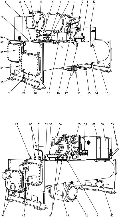
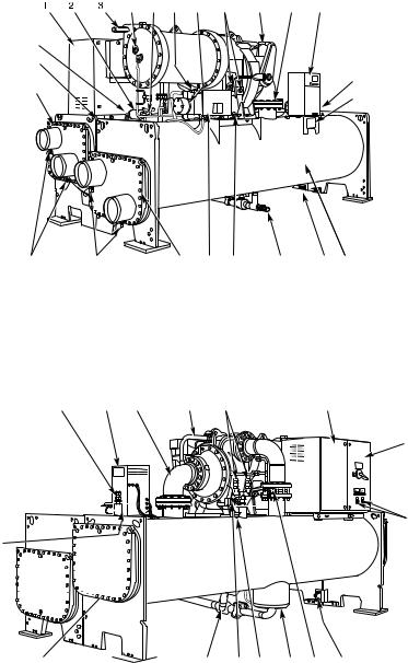
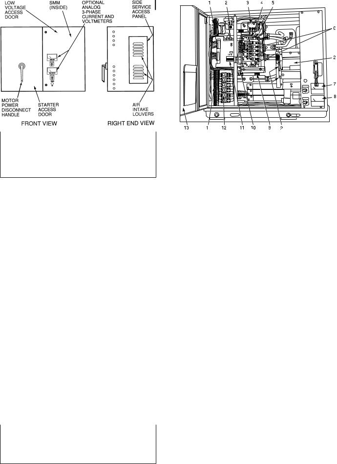
CHILLER FAMILIARIZATION (Fig. 1, 2A, and 2B)
Chiller Information Plate Ð The information plate is located on the right side of the chiller control center panel.
Fig. 1 Ð 19XL Identi®cation
System Components Ð The components include the cooler and condenser heat exchangers in separate vessels, motor-compressor, lubrication package, control center, and motor starter. All connections from pressure vessels have external threads to enable each component to be pressure tested with a threaded pipe cap during factory assembly.
Cooler Ð This vessel (also known as the evaporator) is located underneath the compressor. The cooler is maintained at lower temperature/pressure so that evaporating refrigerant can remove heat from water ¯owing through its internal tubes.
Condenser Ð The condenser operates at a higher temperature/pressure than the cooler, and has water ¯owing through its internal tubes in order to remove heat from the refrigerant.
Motor-Compressor Ð This component maintains system temperature/pressure differences and moves the heat carrying refrigerant from the cooler to the condenser.
Control Center Ð The control center is the user interface for controlling the chiller. It regulates the chiller's capacity as required to maintain proper leaving chilled water temperature. The control center:
·registers cooler, condenser, and lubricating system pressures
·shows chiller operating condition and alarm shutdown conditions
·records the total chiller operating hours
·sequences chiller start, stop, and recycle under microprocessor control
·provides access to other CCN (Carrier Comfort Network) devices
Factory-Mounted Starter (Optional) Ð The starter allows the proper start and disconnect of electrical energy for the compressor-motor, oil pump, oil heater, and control panels.
Storage Vessel (Optional) Ð There are 2 sizes of storage vessels available. The vessels have double relief
valves, a magnetically coupled dial-type refrigerant level gage, a one-inch FPT drain valve, and a 1¤2-in. male ¯are vapor connection for the pumpout unit. A 30-in.-0-400 psi (±101-0-2750 kPa) gage also is supplied with each unit.
NOTE: If a storage vessel is not used at the jobsite, factoryinstalled isolation valves on the chiller may be used to isolate the chiller charge in either the cooler or condenser. An optional pumpout compressor system is used to transfer refrigerant from vessel to vessel.
REFRIGERATION CYCLE
The compressor continuously draws refrigerant vapor from the cooler, at a rate set by the amount of guide vane opening. As the compressor suction reduces the pressure in the cooler, the remaining refrigerant boils at a fairly low temperature (typically 38 to 42 F [3 to 6 C]). The energy required for boiling is obtained from the water ¯owing through the cooler tubes. With heat energy removed, the water becomes cold enough for use in an air conditioning circuit or process liquid cooling.
After taking heat from the water, the refrigerant vapor is compressed. Compression adds still more heat energy and the refrigerant is quite warm (typically 98 to 102 F [37 to 40 C]) when it is discharged from the compressor into the condenser.
Relatively cool (typically 65 to 90 F [18 to 32 C]) water ¯owing into the condenser tubes removes heat from the refrigerant and the vapor condenses to liquid.
The liquid refrigerant passes through ori®ces into the FLASC (Flash Subcooler) chamber (Fig. 3). Since the FLASC chamber is at a lower pressure, part of the liquid refrigerant ¯ashes to vapor, thereby cooling the remaining liquid. The FLASC vapor is recondensed on the tubes which are cooled by entering condenser water. The liquid drains into a ¯oat chamber between the FLASC chamber and cooler. Here a ¯oat valve forms a liquid seal to keep FLASC chamber vapor from entering the cooler. When liquid refrigerant passes through the valve, some of it ¯ashes to vapor in the reduced pressure on the cooler side. In ¯ashing, it removes heat from the remaining liquid. The refrigerant is now at a temperature and pressure at which the cycle began.
MOTOR/OIL REFRIGERATION
COOLING CYCLE
The motor and the lubricating oil are cooled by liquid refrigerant taken from the bottom of the condenser vessel (Fig. 3). Flow of refrigerant is maintained by the pressure differential that exists due to compressor operation. After the refrigerant ¯ows past an isolation valve, an in-line ®lter, and a sight glass/moisture indicator, the ¯ow is split between motor cooling and oil cooling systems.
Flow to the motor ¯ows through an ori®ce and into the motor. There is also another ori®ce and a solenoid valve which will open if additional motor cooling is required. Once past the ori®ce, the refrigerant is directed over the motor by a spray nozzle. The refrigerant collects in the bottom of the motor casing and then is drained back into the cooler through the motor refrigerant drain line. A back pressure valve or an ori®ce in this line maintains a higher pressure in the motor shell than in the cooler/oil sump. The motor is protected by a temperature sensor imbedded in the stator windings. Higher motor temperatures (above 125 F [51 C]) energize a solenoid to provide additional motor cooling. A further increase in temperature past the motor override set point will override the temperature capacity control to hold, and if the motor temperature rises 10° F (5.5° C) above this set point, will close the inlet guide vanes. If the temperature rises above the safety limit, the compressor will shut down.
5
|
LEGEND |
1 |
Ð Unit-Mounted Starter |
2 |
Ð Refrigerant Filter Drier |
3 |
Ð Rigging Guide Bolt |
4 |
Ð Refrigerant Moisture Indicator |
5 |
Ð Motor Sight Glass |
6 |
Ð Refrigerant Motor Drain |
7 |
Ð Oil Filter Access Cover |
8 |
Ð Refrigerant Oil Cooler |
9 |
Ð Oil Level Sight Glasses |
10 |
Ð Guide Vane Actuator |
11 |
Ð Typical Flange Connection |
12 |
Ð Control Center |
13 |
Ð ASME Nameplate, Cooler |
14 |
Ð Take-Apart, Rabbet Fit Connector |
|
(Lower) |
15 |
Ð Refrigerant Charging Valve |
16 |
Ð Cooler Refrigerant Isolation Valve |
17 |
Ð Cooler Pressure Schrader Fittings |
18 |
Ð Oil Drain/Charging Valve |
19 |
Ð Power Panel |
20 |
Ð Retro-Fit, Rig-in-Place Beams |
21 |
Ð Typical Waterbox Drain Port |
22 |
Ð Take-Apart, Shell Leveling Feet |
23 |
Ð Cooler Return-End Waterbox Cover |
24 |
Ð ASME Nameplate, Condenser |
25 |
Ð Condenser Return-End Waterbox Cover |
26 |
Ð Take-Apart, Rabbet Fit Connector |
|
(Upper) |
27 |
Ð Protective Truck Holddown Lugs |
28 |
Ð Refrigerant Cooling Isolation Valve |
19XL FRONT VIEW |
(Hidden) |
|
LEGEND
29 Ð Pumpdown System Connection
30 Ð Cooler Relief Valves
31 Ð Chiller Identi®cation Nameplate
32 Ð Cooler Pressure Transducer
33 Ð Suction Elbow
34 Ð Transmission Vent Line
35 Ð Discharge Pressure Switch and
Discharge Pressure Transducer
36 Ð Condenser Isolation Valve
37 Ð Low-Voltage Access Door, Starter
38 Ð Medium-Voltage Access Door, Starter
39 Ð Amp/Volt Gages
40 Ð Refrigerant Supply Sump
41 Ð Condenser Pressure Transducer
42 Ð Liquid Seal Float Chamber
43 Ð ASME Nameplate, Float Chamber
44 Ð Condenser Relief Valves
45 Ð Condenser In/Out Temperature Sensors
46 Ð Cooler In/Out Temperature Sensors
19XL REAR VIEW
Fig. 2A Ð Typical 19XL Components Ð Design I
6
|
|
|
|
|
|
|
|
|
|
LEGEND |
|
4 |
5 |
6 |
7 |
8 |
9 |
10 |
11 |
1 |
Ð Unit-Mounted Starter |
|
2 |
Ð Refrigerant Filter Drier |
||||||||
|
|
|
|
|
|
|
|
|
||
|
|
|
|
|
|
|
|
|
3 |
Ð Rigging Guide Bolt |
24 |
|
|
|
|
|
|
|
|
4 |
Ð Motor Sight Glass |
|
|
|
|
|
|
|
|
5 |
Ð Refrigerant Moisture Indicator |
|
23 |
|
|
|
|
|
|
|
|
6 |
Ð Refrigerant Oil Cooler |
|
|
|
|
|
|
|
|
12 |
7 |
Ð Oil Filter Access Cover |
22 |
|
|
|
|
|
|
|
8 |
Ð Oil Level Sight Glasses |
|
|
|
|
|
|
|
|
13 |
9 |
Ð Guide Vane Actuator |
|
|
|
|
|
|
|
|
|
10 |
Ð Typical Flange Connection |
|
|
|
|
|
|
|
|
|
|
||
|
|
|
|
|
|
|
|
|
11 |
Ð Control Center |
|
|
|
|
|
|
|
|
|
12 |
Ð Cooler Pressure Schrader Fitting |
|
|
|
|
|
|
|
|
|
|
(Hidden) |
|
|
|
|
|
|
|
|
|
13 |
Ð ASME Nameplate, Cooler |
|
|
|
|
|
|
|
|
|
14 |
Ð Cooler |
|
|
|
|
|
|
|
|
|
15 |
Ð Take-Apart Rabbet Fit Connector |
|
|
|
|
|
|
|
|
|
|
(Lower) |
|
|
|
|
|
|
|
|
|
16 |
Ð Refrigerant Charging Valve |
|
|
|
|
|
|
|
|
|
17 |
Ð Oil Drain/Charging Valve |
|
|
|
|
|
|
|
|
|
18 |
Ð Power Panel |
|
|
|
|
|
|
|
|
|
19 |
Ð Cooler Waterbox Cover |
|
|
|
|
|
|
|
|
|
20 |
Ð Cooler In/Out Temperature Sensors |
21 |
20 |
|
|
19 |
18 |
17 |
16 |
15 14 |
21 |
Ð Condenser In/Out Temperature Sensors |
|
|
22 |
Ð Condenser Waterbox Cover |
|||||||
|
|
19XL FRONT VIEW |
|
|
23 |
Ð Take-Apart Rabbet Fit Connector |
||||
|
|
|
|
|
(Upper) |
|||||
|
|
|
|
|
|
|
|
|
24 |
Ð Refrigerant Cooling Isolation Valve |
|
|
|
|
|
|
|
|
|
|
(Hidden) |
25 |
26 |
27 |
28 |
29 |
30 |
31
42 


32
41
40 

 39
39 

38  37 36 35 34 33 15
LEGEND
25Ð Cooler Relief Valve
26Ð Chiller Identi®cation Plate
27Ð Suction Elbow
28Ð Transmission Vent Line
29Ð Condenser Relief Valves
30Ð Low Voltage Access Door, Starter
31Ð Medium Voltage Access Door, Starter
32Ð Amp/Volt Gages
33Ð Condenser Isolation Valve
34Ð Linear Float Valve Chamber
35Ð Condenser Pressure Transducer
36Ð Discharge Pressure Switch and Discharge Pressure Transducer
37Ð Cooler Refrigerant Isolation Valve
38Ð Condenser Return End Waterbox Cover
39Ð Typical Waterbox Drain Port
40Ð Cooler Return End Waterbox Cover
41Ð Cooler Pressure Transducer
42Ð Pumpdown Valve
19XL REAR VIEW
Fig. 2B Ð Typical 19XL Components Ð Design II
7
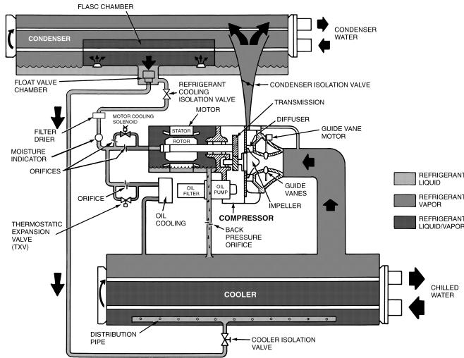
Fig. 3 Ð Refrigerant Motor Cooling and Oil Cooling Cycles
Refrigerant that ¯ows to the oil cooling system is regulated by a thermostatic expansion valve. There is always a minimum ¯ow bypassing the TXV, which ¯ows through an ori®ce. The TXV valve regulates ¯ow into the oil/ refrigerant plate and frame-type heat exchanger. The bulb for the expansion valve controls oil temperature to the bearings. The refrigerant leaving the heat exchanger then returns to the cooler.
LUBRICATION CYCLE
Summary Ð The oil pump, oil ®lter, and oil cooler make up a package located partially in the transmission casting of the compressor-motor assembly. The oil is pumped into a ®lter assembly to remove foreign particles, and is then forced into an oil cooler heat exchanger where the oil is cooled to proper operational temperatures. After the oil cooler, part of the ¯ow is directed to the gears and the high speed shaft bearings; the remaining ¯ow is directed to the motor shaft bearings. Oil drains into the transmission oil sump to complete the cycle (Fig. 4).
Details Ð Oil is charged into the lubrication system through a hand valve. Two sight glasses in the oil reservoir permit oil level observation. Normal oil level is between the middle of the upper sight glass and the top of the lower sight glass
when the compressor is shut down. The oil level should be visible in at least one of the 2 sight glasses during operation. Oil sump temperature is displayed on the LID default screen. Oil sump temperature ranges during compressor operation between 100 to 120 F (37 to 49 C) [120 to 140 F (49 to 60 C)].
The oil pump suction is fed from the oil reservoir. An oil pressure relief valve maintains 18 to 25 psid (124 to 172 kPad) differential pressure in the system at the pump discharge. This differential pressure can be read directly from the Local Interface Device (LID) default screen. The oil pump discharges oil to the oil ®lter assembly. This ®lter can be valved closed to permit removal of the ®lter without draining the entire oil system (see Maintenance sections, pages 61 to 65, for details). The oil is then piped to the oil cooler. This heat exchanger uses refrigerant from the condenser as the coolant. The refrigerant cools the oil to a temperature between 100 and 120 F (37 to 49 C).
As the oil leaves the oil cooler, it passes the oil pressure transducer and the thermal bulb for the refrigerant expansion valve on the oil cooler. The oil is then divided, with a portion ¯owing to the thrust bearing, forward pinion bearing, and gear spray. The balance then lubricates the motor shaft bearings and the rear pinion bearing. The oil temperature is measured as the oil leaves the thrust and forward
8

Fig. 4 Ð Lubrication System
journal bearings within the bearing housing. The oil then drains into the oil reservoir at the base of the compressor. The PIC (Product Integrated Control) measures the temperature of the oil in the sump and maintains the temperature during shutdown (see Oil Sump Temperature Control section, page 32). This temperature is read on the LID default screen.
During the chiller start-up, the PIC will energize the oil pump and provide 15 seconds of prelubrication to the bearings after pressure is veri®ed before starting the compressor. During shutdown, the oil pump will run for 60 seconds to post-lubricate after the compressor shuts down. The oil pump can also be energized for testing purposes in the Control Test.
Ramp loading can slow the rate of guide vane opening to minimize oil foaming at start-up. If the guide vanes open quickly, the sudden drop in suction pressure can cause any refrigerant in the oil to ¯ash. The resulting oil foam cannot be pumped efficiently; therefore, oil pressure falls off and lubrication is poor. If oil pressure falls below 15 psid (103 kPad) differential, the PIC will shut down the compressor.
Oil Reclaim System Ð The oil reclaim system operates to return oil back to the oil reservoir by recovering it from 2 areas on the chiller. The primary area of recovery is from the guide vane housing. Oil also is recovered, along with refrigerant, from the cooler.
Any refrigerant that enters the oil reservoir/transmission area is ¯ashed into gas. The demister line at the top of the
casing will vent this refrigerant into the suction of the compressor. Oil entrained in the refrigerant is eliminated by the demister ®lter.
DURING NORMAL CHILLER OPERATION, oil is entrained with the refrigerant. As the compressor pulls the refrigerant into the guide vane housing to be compressed, the oil will normally drop out at this point and fall to the bottom of the housing where it accumulates. Using discharge gas pressure to power an eductor, the oil is vacuumed from the housing by the eductor and is discharged into the oil reservoir. Oil and refrigerant are also recovered from the top of the cooler refrigerant level and are discharged into the guide vane housing. The oil will drop to the bottom of the guide vane housing and be recovered by the eductor system.
DURING LIGHT LOAD CONDITIONS, the suction gas into the compressor does not have enough velocity to return oil, which is ¯oating in the cooler back to the compressor. In addition, the eductor may not have enough power to pull the oil from the guide vane housing back into the oil reservoir due to extremely low pressure at the guide vanes. Two solenoids, located on the oil reclaim piping, are operated so that the eductor can pull oil and refrigerant directly from the cooler and discharge the mixture into the oil reservoir. The oil reclaim solenoids are operated by an auxiliary contact integral to the guide vane actuator. This switchover of the solenoids occurs when the guide vanes are opened beyond 30 degrees from the closed position.
9
STARTING EQUIPMENT
The 19XL requires a motor starter to operate the centrifugal hermetic compressor motor, the oil pump, and various auxiliary equipment. The starter serves as the main ®eld wiring interface for the contractor.
Three types of starters are available from Carrier Corporation: solid-state, wye-delta, and across-the-line starters. See Carrier Speci®cation Z-375 for speci®c starter requirements. All starters must meet these speci®cations in order to properly start and satisfy mechanical safety requirements. Starters may be supplied as separate, free-standing units, or may be mounted directly on the chiller (unit mounted) for low-voltage units only.
Inside the starter are 3 separate circuit breakers. Circuit breaker CB1 is the compressor motor circuit breaker. The disconnect switch on the starter front cover is connected to this breaker. Circuit breaker CB1 supplies power to the compressor motor.
The main circuit breaker (CB1) on the front of the starter disconnects the main motor current only. Power is still energized for the other circuits. Two more circuit breakers inside the starter must be turned off to disconnect power to the oil pump, PIC controls, and oil heater.
Circuit breaker CB2 supplies power to the control center, oil heater, and portions of the starter controls. Circuit breaker CB3 supplies power to oil pump. Both of these circuit breakers are wired in parallel with CB1 so that power is supplied to them if the CB1 disconnect is open.
All starters are shipped with a Carrier control module called the Starter Management Module (SMM). This module controls and monitors all aspects of the starter. See the Controls section on page 11 for additional SMM information. All starter replacement parts are supplied by the starter manufacturer.
Unit-Mounted Solid-State Starter (Optional) Ð The 19XL may be equipped with a solid-state, reducedvoltage starter (Fig. 5 and 6). This starter provides on-off control of the compressor motor as its primary function. Using this type of starter reduces the peak starting torque, reduces the motor inrush current, and decreases mechanical shock. This is summed up by the phrase ``soft starting.''
Two varieties of solid-state starters are available as a 19XL option (factory supplied and installed). When a unit-mounted, optional, solid-state starter is purchased with the 19XL, a Benshaw, Inc. solid-state starter will be shipped with the unit. See Fig. 5. The solid-state starter's manufacturer name will be located inside the starter access door. See Fig. 6.
These starters operate by reducing the starting voltage. The starting torque of a motor at full voltage is typically 125% to 175% of the running torque. When the voltage and the current are reduced at start-up, the starting torque is reduced as well. The object is to reduce the starting voltage to just the voltage necessary to develop the torque required to get the motor moving. The voltage and current are then ramped up in a desired period of time. The voltage is reduced through the use of silicon controlled recti®ers (SCR). Once full voltage is reached, a bypass contactor is energized to bypass the SCRs.
When voltage is supplied to the solid-state circuitry, the heat sinks within the starter are at line voltage. Do not touch the heat sinks while voltage is present or serious injury will result.
10
LEGEND
1Ð Field Wiring Terminal Strips (TB2 and TB3)
2Ð Circuit Breaker 1, 2, 3, 4
3Ð Overload Unit
4Ð Solid-State Controller
5Ð Silicon Controlled Recti®er (SCR) LED (One of 6)
6Ð Starter Fault and Run LEDs
7Ð Voltmeter (Optional)
8Ð Ammeter (Optional)
9Ð SCR (One of 6)
10Ð Voltage LED
11Ð Starter Management Module (SMM)
12Ð Pilot Relays (PR1 to PR5)
13Ð Starter Access Door
Fig. 5 Ð Benshaw, Inc. Solid-State Starter,
Internal View
Fig. 6 Ð Typical Starter External View
(Solid-State Starter Shown)
There are a number of LEDs (light-emitting diodes) that are useful in troubleshooting and starter check-out on Benshaw, Inc. solid-state starters. These are used to indicate:
·voltage to the SCRs
·SCR control voltage
·power indication
·proper phasing for rotation
·start circuit energized
·overtemperature
·ground fault
·current unbalance
·run state
These LEDs are further explained in the Check Starter and Troubleshooting Guide section, page 66.
Unit-Mounted Wye-Delta Starter (Optional) Ð The 19XL chiller may be equipped with a wye-delta starter mounted on the unit (Fig. 7). This starter is intended for use with lowvoltage motors (under 600 v). It reduces the starting current inrush by connecting each phase of the motor windings into a wye con®guration. This occurs during the starting period when the motor is accelerating up to speed. After a time delay, once the motor is up to speed, the starter automatically connects the phase windings into a delta con®guration.
|
1 |
|
2 |
|
|
|
3 |
|
|
4 |
5 |
6 |
|
|
|
|
7 |
|
|||||||||||||||||||||||||
|
|
|
|
|
|
|
|
|
|
|
|
|
|
|
|
|
|
|
|
|
|
|
|
|
|
|
|
|
|
|
|
|
|
|
|
|
|
|
|
|
|
|
|
|
|
|
|
|
|
|
|
|
|
|
|
|
|
|
|
|
|
|
|
|
|
|
|
|
|
|
|
|
|
|
|
|
|
|
|
|
|
|
|
|
|
|
|
|
|
|
|
|
|
|
|
|
|
|
|
|
|
|
|
|
|
|
|
|
|
|
|
|
|
|
|
|
|
|
|
|
|
|
|
|
|
|
|
|
|
|
|
|
|
|
|
|
|
|
|
|
|
|
|
|
|
|
|
|
|
|
|
|
|
|
|
|
|
|
|
|
|
|
|
|
|
|
|
|
|
|
|
|
|
|
|
|
|
|
|
|
|
|
|
|
|
|
|
|
|
|
|
|
|
|
|
|
|
|
|
|
|
|
|
|
|
|
|
|
|
|
|
|
|
|
|
|
|
|
|
|
|
|
|
|
|
|
|
|
|
|
|
|
|
|
|
|
|
|
|
|
|
|
|
|
|
|
|
|
|
|
|
|
|
|
|
|
|
|
|
|
|
|
|
17 |
|
16 |
8 |
15 |
|
14 |
13 |
12 |
11 |
10 |
9 |
LEGEND
1Ð Pilot Relays
2Ð SMM Power Circuit Breaker and Voltage Calibration Potentiometer
3Ð Transistor Resistor Fault Protector (TRFP)
4Ð Transformer (T2)
5Ð Control Power Circuit Breaker
6Ð Oil Pump Circuit Breaker
7Ð Main Circuit Breaker Disconnect
8Ð Voltmeter (Optional)
9Ð Ammeter (Optional)
10Ð Current Transformers (T1, T2, T3)
11Ð Phase Monitor Relay (Optional)
12Ð Overload Unit
13Ð Starter Management Module
14Ð Starter Access Door
15Ð Control Transformer Secondary Circuit Breaker
16Ð Signal Resistor
17Ð Field Wiring Terminal Strip (TB6)
Fig. 7 Ð Wye-Delta Starter, Internal View
CONTROLS
De®nitions
ANALOG SIGNAL Ð An analog signal varies in proportion to the monitored source. It quanti®es values between operating limits. (Example: A temperature sensor is an analog device because its resistance changes in proportion to the temperature, generating many values.)
DIGITAL SIGNAL Ð A digital (discrete) signal is a 2-position representation of the value of a monitored source. (Example: A switch is a digital device because it only indicates whether a value is above or below a set point or boundary by generating an on/off, high/low, or open/closed signal.)
VOLATILE MEMORY Ð Volatile memory is memory incapable of being sustained if power is lost and subsequently restored.
The memory of the PSIO and LID modules are volatile. If the battery in a module is removed or damaged, all programming will be lost.
General Ð The 19XL hermetic centrifugal liquid chiller contains a microprocessor-based control center that monitors and controls all operations of the chiller. The microprocessor control system matches the cooling capacity of the chiller to the cooling load while providing state-of-the-art chiller protection. The system controls cooling load within the set point plus the deadband by sensing the leaving chilled water or brine temperature, and regulating the inlet guide vane via a mechanically linked actuator motor. The guide vane is a variable ¯ow prewhirl assembly that controls the refrigeration effect in the cooler by regulating the amount of refrigerant vapor ¯ow into the compressor. An increase in guide vane opening increases capacity. A decrease in guide vane opening decreases capacity. Chiller protection is provided by the processor which monitors the digital and analog inputs and executes capacity overrides or safety shutdowns, if required.
PIC System Components Ð The Product Integrated Control (PIC) is the control system on the chiller. See Table 1. The PIC controls the operation of the chiller by monitoring all operating conditions. The PIC can diagnose a problem and let the operator know what the problem is and what to check. It promptly positions the guide vanes to maintain leaving chilled water temperature. It can interface with auxiliary equipment such as pumps and cooling tower fans to turn them on only when required. It continually checks all safeties to prevent any unsafe operating condition. It also regulates the oil heater while the compressor is off, and the hot gas bypass valve, if installed.
The PIC can be interfaced with the Carrier Comfort Network (CCN) if desired. It can communicate with other PICequipped chillers and other CCN devices.
The PIC consists of 3 modules housed inside the 3 major components. The component names and the control voltage contained in each component are listed below (also see Table 1):
·control center Ð all extra low-voltage wiring (24 v or less)
·power panel Ð 230 or 115 v control voltage (per job
requirement)
Ðup to 600 v for oil pump power
·starter cabinet Ð chiller power wiring (per job
requirement)
Table 1 Ð Major PIC Components and
Panel Locations*
PIC COMPONENT |
PANEL |
|
LOCATION |
||
|
||
Processor Sensor Input/Output Module |
Control Center |
|
(PSIO) |
||
|
||
Starter Management Module (SMM) |
Starter Cabinet |
|
Local Interface Device (LID) |
Control Center |
|
6-Pack Relay Board |
Control Center |
|
8-Input Modules (Optional) |
Control Center |
|
Oil Heater Contactor (1C) |
Power Panel |
|
Oil Pump Contactor (2C) |
Power Panel |
|
Hot Gas Bypass Relay (3C) (Optional) |
Power Panel |
|
Control Transformers (T1-T4) |
Power Panel |
|
Control and Oil Heater Voltage Selector (S1) |
Power Panel |
|
Temperature Sensors |
See Fig. 8 |
|
Pressure Transducers |
See Fig. 8 |
|
|
|
|
*See Fig. 5, 6, and Fig. 8-12. |
|
11
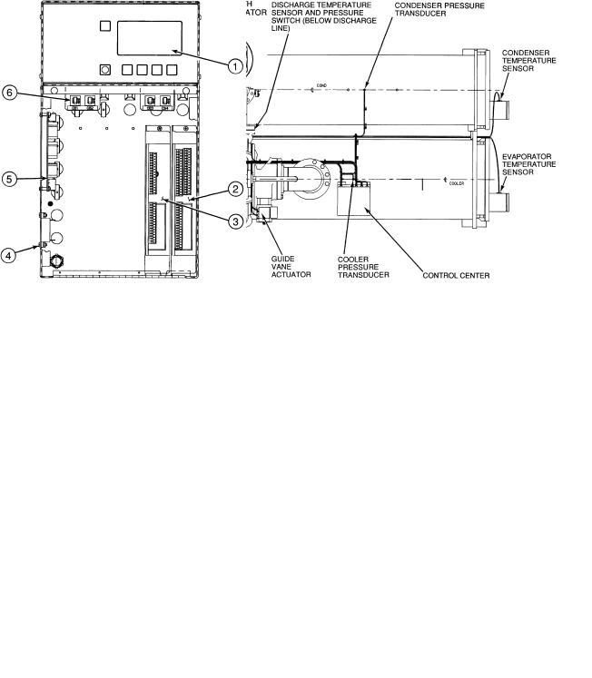
Fig. 8 Ð 19XL Controls and Sensor Locations
Fig. 9 Ð Control Sensors
(Temperature)
|
|
LEGEND |
|
1 |
Ð LID |
|
2 |
Ð PSIO |
Fig. 10 Ð Control Sensors |
3 |
Ð 8-Input Module (One of 2 Available) |
4 Ð 5-Volt Transducer Power Supply |
||
(Pressure Transducer, Typical) |
5 Ð 6-Pack Relay Board |
|
|
6 |
Ð Circuit Breakers (4) |
Fig. 11 Ð Control Center (Front View),
with Options Module
12
PROCESSOR MODULE (PSIO) Ð The PSIO is the brain of the PIC (Fig. 11). This module contains all the operating software needed to control the chiller. The 19XL uses 3 pressure transducers and 8 thermistors to sense pressures and temperatures. These are connected to the PSIO module. The PSIO also provides outputs to the guide vane actuator, oil pump, oil heater, hot gas bypass (optional), motor cooling solenoid, and alarm contact. The PSIO communicates with the LID, the SMM, and the optional 8-input modules for user interface and starter management.
STARTER MANAGEMENT MODULE (SMM) Ð This module is located within the starter cabinet. This module initiates PSIO commands for starter functions such as start/ stop of the compressor, start/stop of the condenser and chilled water pumps, start/stop of the tower fan, spare alarm contacts, and the shunt trip. The SMM monitors starter inputs such as ¯ow switches, line voltage, remote start contact, spare safety, condenser high pressure, oil pump interlock, motor current signal, starter 1M and run contacts, and kW transducer input (optional). The SMM contains logic capable of safely shutting down the machine if communications with the PSIO are lost.
LOCAL INTERFACE DEVICE (LID) Ð The LID is mounted to the control center and allows the operator to interface with the PSIO or other CCN devices (Fig. 11). It is the input center for all local chiller set points, schedules, set-up functions, and options. The LID has a STOP button, an alarm light, 4 buttons for logic inputs, and a display. The function of the 4 buttons or ``softkeys'' are menu driven and are shown on the display directly above the key.
6-PACK RELAY BOARD Ð This device is a cluster of 6 pilot relays located in the control center (Fig. 11). It is energized by the PSIO for the oil pump, oil heater, alarm, optional hot gas bypass relay, and motor cooling solenoid.
8-INPUT MODULES Ð One optional module is factory installed in the control center panel when ordered (Fig. 11). There can be up to 2 of these modules per chiller with 8 spare inputs each. They are used whenever chilled water reset, demand reset, or reading a spare sensor is required. The sensors or 4 to 20 mA signals are ®eld-installed.
The spare temperature sensors must have the same temperature/resistance curve as the other temperature sensors on this unit. These sensors are 5,000 ohm at 75 F (25 C).
OIL HEATER CONTACTOR (1C) Ð This contactor is located in the power panel (Fig. 12) and operates the heater at either 115 or 230 v. It is controlled by the PIC to maintain oil temperature during chiller shutdown.
OIL PUMP CONTACTOR (2C) Ð This contactor is located in the power panel (Fig. 12). It operates all 200 to 575-v oil pumps. The PIC energizes the contactor to turn on the oil pump as necessary.
HOT GAS BYPASS CONTACTOR RELAY (3C) (Optional) Ð This relay, located in the power panel, (Item 5, Fig. 12) controls the opening of the hot gas bypass valve. The PIC energizes the relay during low load, high lift conditions.
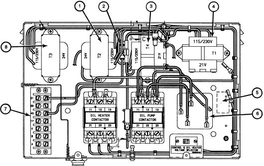
CONTROL TRANSFORMERS (T1-T4) Ð These transformers convert incoming control voltage to either 21 vac power for the PSIO module and options modules, or 24 vac power for 3 power panel contactor relays, 3 control solenoid valves, and the guide vane actuator. They are located in the power panel. See Fig. 12.
CONTROLAND OIL HEATER VOLTAGE SELECTOR (S1) Ð It is possible to use either 115 v or 230 v incoming control power in the power panel. The switch is set to the voltage used at the jobsite.
|
LEGEND |
|
|
1 |
Ð T2 Ð 24 vac Power Transformer for Hot Gas Bypass Relay, |
4 |
Ð T1 Ð 24 vac, Control Center Transformer |
|
Oil Pump Relay, Oil Heater Relay, Motor Cooling Solenoid, |
5 |
Ð 3C Hot Gas Bypass Relay Location |
|
Oil Reclaim Solenoid |
6 |
Ð Oil Pump Terminal Block |
2 |
Ð Oil Pressure Switch |
7 |
Ð Factory Terminal Connections |
3 |
Ð T4 Ð 24 vac, Optional 8-Input Module Transformer |
8 |
Ð T3 Ð 24 vac Guide Vane Actuator Transformer |
Fig. 12 Ð Power Panel with Options
13
LID Operation and Menus (Fig. 13-19)
GENERAL
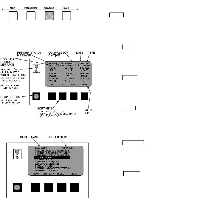
· The LID display will automatically revert to the default screen after 15 minutes if no softkey activity takes place and if the chiller is not in the Pumpdown mode (Fig. 13).
·When not in the default screen, the upper right-hand corner of the LID always displays the name of the screen that you have entered (Fig. 14).
·The LID may be con®gured in English or SI units, through the LID con®guration screen.
·Local Operation Ð By pressing the LOCAL softkey, the
PIC is now in the LOCAL operation mode. The control will accept changes to set points and con®gurations from the LID only. The PIC will use the Local Time Schedule to determine chiller start and stop times.
·CCN Operation Ð By pressing the CCN softkey, the PIC
is now in the CCN operation mode, and the control will accept modi®cations from any CCN interface or module (with the proper authority), as well as the LID. The PIC will use the CCN time schedule to determine start and stop times.
Fig. 13 Ð LID Default Screen
ALARMS AND ALERTS Ð Alarm (*) and alert (!) status are indicated on the Status tables. An alarm (*) will shut down the compressor. An alert (!) noti®es the operator that an unusual condition has occurred. The chiller will continue to operate when an alert is shown.
Alarms are indicated when the control center alarm light
(!) ¯ashes. The primary alarm message is viewed on the default screen and an additional, secondary, message and troubleshooting information are sent to the Alarm History table.
When an alarm is detected, the LID default screen will freeze (stop updating) at the time of alarm. The freeze enables the operator to view the chiller conditions at the time of alarm. The Status tables will show the updated information. Once all alarms have been cleared (by pressing the
RESET softkey), the default LID screen will return to nor-
mal operation.
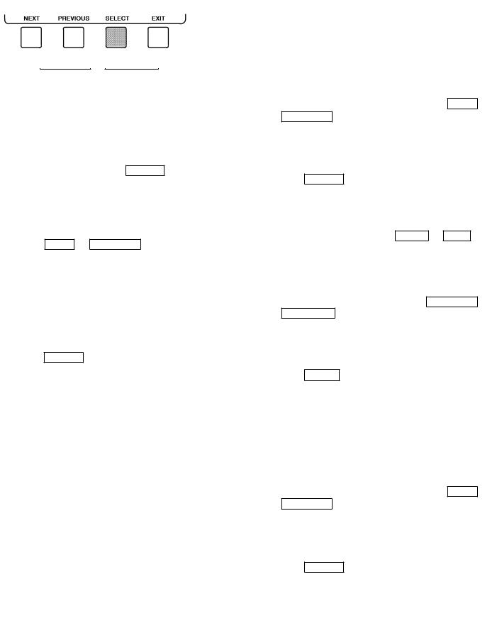
MENU STRUCTURE Ð To perform any of the operations described below, the PIC must be powered up and have successfully completed its self test. The self test takes place automatically, after power-up.
·Press QUIT to leave the selected decision or ®eld without
·Press ENTER to leave the selected decision or ®eld and save
·Press NEXT to scroll the cursor bar down in order to
highlight a point or to view more points below the current screen
·Press PREVIOUS to scroll the cursor bar up in order to highlight
· Press SELECT to view the next screen level (high-
lighted with the cursor bar), or to override (if allowable) the
Fig. 14 Ð LID Service Screen
14
· Press |
|
4. On the Point Status table press |
NEXT |
or |
||
|
|
|
|
|
|
|
|
|
|
|
|
|
|
·Press INCREASE or DECREASE to change the highlighted
TO VIEW POINT STATUS (Fig. 15) Ð Point Status is the actual value of all of the temperatures, pressures, relays, and actuators sensed and controlled by the PIC.
1.On the Menu screen, press STATUS to view the list of Point
2.Press NEXT or PREVIOUS to highlight the desired status table. The list of tables is:
·Status01 Ð Status of control points and sensors
·Status02 Ð Status of relays and contacts
·Status03 Ð Status of both optional 8-input modules and
3. Press
OVERRIDE OPERATIONS
To Override a Value or Status
1. On the Point Status table press NEXT or
2. Press
For Discrete Points Ð Press START or STOP to select
For Analog Points Ð Press INCREASE or
3. Press
NOTE: When overriding or changing metric values, it is necessary to hold the softkey down for a few seconds in order to see a value change, especially on kilopascal values.
To Remove an Override
1. On the Point Status table press NEXT or
2. Press
Fig. 15 − Example of Point Status Screen
(Status01)
15
3. Press |
RELEASE |
to remove the override and return the |
4. Press |
NEXT |
or |
PREVIOUS |
to highlight the de- |
point |
sired |
||||||
Override IndicationÐ An override value is indicated by
``SUPVSR,'' ``SERVC,'' or ``BEST'' ¯ashing next to the point value on the Status table.
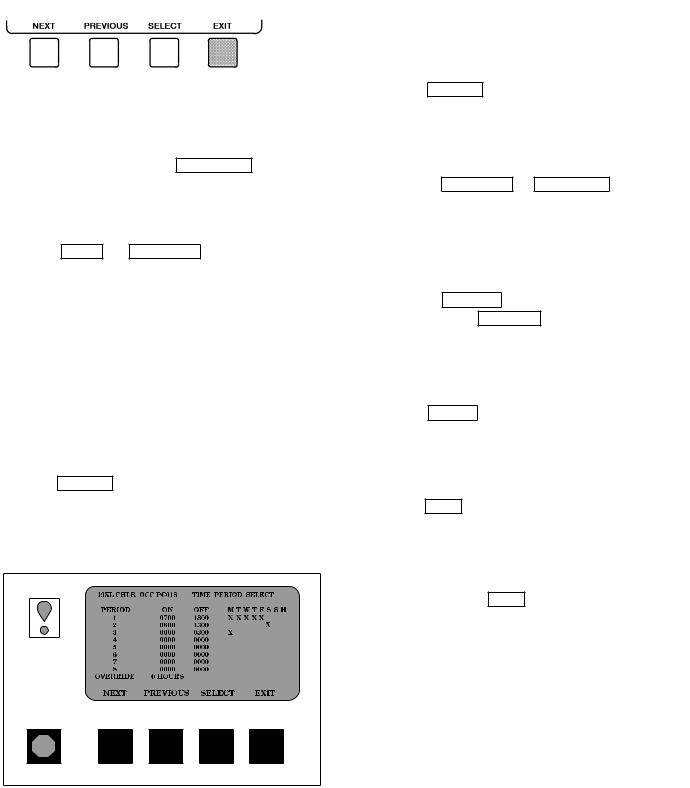
TIME SCHEDULE OPERATION (Fig. 16)
1. On
2.Press NEXT or PREVIOUS to highlight the desired schedule.
PSIO Software Version 08 and lower: OCCPC01S Ð LOCAL Time Schedule OCCPC02S Ð CCN Time Schedule
PSIO Software Version 09 and higher:
OCCPC01S Ð LOCAL Time Schedule OCCPC02S Ð ICE BUILD Time Schedule OCCPC03-99S Ð CCN Time Schedule (Actual
number is de®ned in
3.
5. Press SELECT to access the highlighted period or
6.a. Press INCREASE or DECREASE to change the time values. Override values are in one-hour incre-
b.Press ENABLE to select days in the day-of-week ®elds. Press DISABLE to eliminate days from the
7. Press ENTER to register the values and to move
8.
9. Either return to Step 4 to select another period or
override, or press EXIT again to leave the current time
10. Holiday Designation (HOLIDEF table) may be found in the Service Operation section, page 38. You must assign the month, day, and duration for the holiday. The Broadcast function in the Brodefs table also must be enabled for holiday periods to function.
Fig. 16 Ð Example of Time Schedule
Operation Screen
16

17
*Only available on PSIO Software Version 09 and higher. ²Available on PSIO Software Versions 07 and 08.
Fig. 17 Ð 19XL Menu Structure

18
Fig. 18 Ð 19XL Service Menu Structure

19
*Only available on PSIO Software Version 09 and higher. ²Available on PSIO Software Versions 07 and 08.
Fig. 18 Ð 19XL Service Menu Structure (cont)
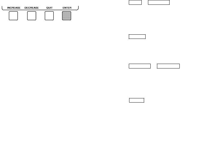
TO VIEW AND CHANGE SET POINTS (Fig. 19)
1.To view the Set Point table, at the Menu screen press SETPOINT .
2.There are 4 set points on this screen: Base Demand Limit; LCW Set Point (leaving chilled water set point); ECW Set Point (entering chilled water set point); and ICE BUILD set point (PSIO Software Version 09 and higher only). Only one of the chilled water set points can be active at one time, and the type of set point is activated in the Service menu. ICE BUILD is also activated and con®gured in the Service menu.
Fig. 19 Ð Example of Set Point Screen
3.Press NEXT or PREVIOUS to highlight the desired set
4. Press
5.Press INCREASE or DECREASE to change the selected
6.Press ENTER to save the changes and return to the previous
SERVICE OPERATION Ð To view the menu-driven programs available for Service Operation, see Service Operation section, page 38. For examples of LID display screens, see Table 2.
20
Table 2 Ð LID Screens
NOTES:
1. Only 12 lines of information appear on the LID screen at any given time. Press NEXT or PREVIOUS to highlight a point or to view points below or above the current screen.
2.The LID may be con®gured in English or SI units, as required, through the LID con®guration screen.
3.Data appearing in the Reference Point Names column is used for CCN operations only.
4.All options associated with ICE BUILD, Lead/Lag, CCN Occupancy Con®guration, and Soft Stopping are only available on PSIO Software Version 9 and higher.
EXAMPLE 1 Ð STATUS01 DISPLAY SCREEN
To access this display from the LID default screen:
1. Press MENU .
2.Press STATUS (STATUS01 will be highlighted).
3.Press SELECT .
|
DESCRIPTION |
RANGE |
UNITS |
REFERENCE POINT NAME |
|||||||||||||||
|
(ALARM HISTORY) |
||||||||||||||||||
|
|
|
|
||||||||||||||||
Control Mode |
Reset, Off, Local, CCN |
|
MODE |
|
|
|
|||||||||||||
Run Status |
Timeout, Recycle, Startup, |
|
|
|
|
|
|
|
|
|
|
|
|
|
|
|
|
|
|
Ramping, Running, Demand, Override, |
STATUS |
||||||||||||||||||
Occupied ? |
Shutdown, Abnormal, Pumpdown |
|
|
|
|
|
|
|
|
|
|
|
|
|
|
|
|
||
No/Yes |
|
OCC |
|
|
|
||||||||||||||
Alarm State |
Normal/Alarm |
|
ALM |
|
|
|
|||||||||||||
*Chiller Start/Stop |
Stop/Start |
|
CHIL |
|
|
|
|
S |
|
S |
|||||||||
Base Demand Limit |
40-100 |
% |
DLM |
|
|
|
|||||||||||||
*Active Demand Limit |
40-100 |
% |
DEM |
|
|
|
|
|
LIM |
||||||||||
Compressor Motor Load |
0-999 |
% |
CA |
|
|
|
|
|
|
|
|
L |
|
|
|
||||
|
Current |
0-999 |
% |
CA |
|
|
|
|
|
|
|
|
P |
|
|
|
|||
|
Amps |
0-999 |
AMPS |
CA |
|
|
|
|
|
|
|
|
A |
|
|
|
|||
*Target Guide Vane Pos |
0-100 |
% |
GV |
|
|
|
|
|
|
|
TRG |
||||||||
Actual Guide Vane Pos |
0-100 |
% |
GV |
|
|
|
|
|
|
|
ACT |
||||||||
Water/Brine: Setpoint |
10-120 (±12.2-48.9) |
DEG F (DEG C) |
SP |
|
|
|
|
|
|
|
|
|
|
|
|
||||
* |
Control Point |
10-120 (±12.2-48.9) |
DEG F (DEG C) |
LCW |
|
|
STPT |
||||||||||||
Entering Chilled Water |
±40-245 (±40-118) |
DEG F (DEG C) |
ECW |
|
|
|
|||||||||||||
Leaving Chilled Water |
±40-245 (±40-118) |
DEG F (DEG C) |
LCW |
|
|
|
|||||||||||||
Entering Condenser Water |
±40-245 (±40-118) |
DEG F (DEG C) |
ECDW |
|
|
|
|||||||||||||
Leaving Condenser Water |
±40-245 (±40-118) |
DEG F (DEG C) |
LCDW |
|
|
|
|||||||||||||
Evaporator Refrig Temp |
±40-245 (±40-118) |
DEG F (DEG C) |
ERT |
|
|
|
|||||||||||||
Evaporator Pressure |
±6.7-420 (±46-2896) |
PSI (kPa) |
ERP |
|
|
|
|||||||||||||
Condenser Refrig Temp |
±40-245 (±40-118) |
DEG F (DEG C) |
CRT |
|
|
|
|||||||||||||
Condenser Pressure |
±6.7-420 (±46-2896) |
PSI (kPa) |
CRP |
|
|
|
|||||||||||||
Discharge Temperature |
±40-245 (±40-118) |
DEG F (DEG C) |
CMPD |
|
|
|
|||||||||||||
Bearing Temperature |
±40-245 (±40-118) |
DEG F (DEG C) |
MTRB |
|
|
|
|||||||||||||
Motor Winding Temp |
±40-245 (±40-118) |
DEG F (DEG C) |
MTRW |
|
|
|
|||||||||||||
Oil Sump Temperature |
±40-245 (±40-118) |
DEG F (DEG C) |
OILT |
|
|
|
|||||||||||||
Oil Pressure Transducer |
±6.7-420 (±46-2896) |
PSI (kPa) |
OILP |
|
|
|
|||||||||||||
Oil Pressure |
±6.7-420 (±46-2896) |
PSID (kPad) |
OILPD |
|
|
|
|||||||||||||
Line Voltage: Percent |
0-999 |
% |
V |
|
|
|
P |
|
|
|
|||||||||
|
Actual |
0-9999 |
VOLTS |
V |
|
|
|
A |
|
|
|
||||||||
*Remote Contacts Input |
Off/On |
|
REMCON |
||||||||||||||||
Total Compressor Starts |
0-65535 |
|
c |
|
|
starts |
|||||||||||||
Starts in 12 Hours |
0-8 |
|
STARTS |
||||||||||||||||
Compressor Ontime |
0-500000.0 |
HOURS |
c |
|
|
hrs |
|
|
|
||||||||||
*Service Ontime |
0-32767 |
HOURS |
S |
|
|
|
HRS |
||||||||||||
*Compressor Motor kW |
0-9999 |
kW |
CKW |
|
|
|
|||||||||||||
|
|
|
|
|
|
|
|
|
|
|
|
|
|
|
|
|
|
|
|
NOTE: All values are variables available for read operation to a CCN. Descriptions shown with (*) support write operations for BEST programming language, data transfer, and overriding.
21
Table 2 Ð LID Screens (cont)
EXAMPLE 2 Ð STATUS02 DISPLAY SCREEN
To access this display from the LID default screen: 1. Press MENU .
2.Press STATUS .
3.Scroll down to highlight STATUS02.
4.Press SELECT .
DESCRIPTION |
POINT TYPE |
UNITS |
REFERENCE POINT NAME |
|||||||||||
INPUT |
OUTPUT |
(ALARM HISTORY) |
||||||||||||
|
|
|||||||||||||
Hot Gas Bypass Relay |
|
X |
OFF/ON |
HGBR |
||||||||||
*Chilled Water Pump |
|
X |
OFF/ON |
CHWP |
||||||||||
Chilled Water Flow |
X |
|
NO/YES |
EVFL |
||||||||||
*Condenser Water Pump |
|
X |
OFF/ON |
CDP |
|
|
|
|
||||||
Condenser Water Flow |
X |
|
NO/YES |
CDFL |
||||||||||
Compressor Start Relay |
|
X |
OFF/ON |
CMPR |
||||||||||
Compressor Start Contact |
X |
|
OPEN/CLOSED |
1CR |
|
|
|
|
|
|
AUX |
|||
Compressor Run Contact |
X |
|
OPEN/CLOSED |
RUN |
|
|
|
|
AUX |
|||||
Starter Fault Contact |
X |
|
OPEN/CLOSED |
STR |
|
|
|
|
FLT |
|||||
Pressure Trip Contact |
X |
|
OPEN/CLOSED |
PRS |
|
|
|
|
TRIP |
|||||
Single Cycle Dropout |
X |
|
NORMAL/ALARM |
V1 |
|
CYCLE |
||||||||
Oil Pump Relay |
|
X |
OFF/ON |
OILR |
|
|
|
|
||||||
Oil Heater Relay |
|
X |
OFF/ON |
OILH |
|
|
|
|
||||||
Motor Cooling Relay |
|
X |
OFF/ON |
MTRC |
||||||||||
*Tower Fan Relay |
|
X |
OFF/ON |
TFR |
|
|
|
|
||||||
Compr. Shunt Trip Relay |
|
X |
OFF/ON |
TRIPR |
||||||||||
Alarm Relay |
|
X |
NORMAL/ALARM |
ALM |
|
|
|
|
||||||
Spare Prot Limit Input |
X |
|
ALARM/NORMAL |
SPR |
|
|
|
|
PL |
|||||
|
|
|
|
|
||||||||||
NOTE: All values are variables available for read operation to a CCN. Descriptions shown with (*) support write operations from the LID only.
EXAMPLE 3 Ð STATUS03 DISPLAY SCREEN
To access this display from the LID default screen: 1. Press MENU .
2.Press STATUS .
3.Scroll down to highlight STATUS03.
4.Press SELECT .
DESCRIPTION |
RANGE |
UNITS |
REFERENCE POINT NAME |
|||||||||
(ALARM HISTORY) |
||||||||||||
|
|
|
||||||||||
OPTIONS BOARD 1 |
|
|
|
|
|
|
|
|
|
|
|
|
*Demand Limit 4-20 mA |
4-20 |
mA |
DEM |
|
|
OPT |
||||||
*Temp Reset 4-20 mA |
4-20 |
mA |
RES |
|
|
OPT |
||||||
*Common CHWS Sensor |
±40-245 (±40-118) |
DEG F (DEG C) |
CHWS |
|
|
|
||||||
*Common CHWR Sensor |
±40-245 (±40-118) |
DEG F (DEG C) |
CHWR |
|
|
|
||||||
*Remote Reset Sensor |
±40-245 (±40-118) |
DEG F (DEG C) |
R |
|
RESET |
|||||||
*Temp Sensor Ð Spare 1 |
±40-245 (±40-118) |
DEG F (DEG C) |
SPARE1 |
|
||||||||
*Temp Sensor Ð Spare 2 |
±40-245 (±40-118) |
DEG F (DEG C) |
SPARE2 |
|
||||||||
*Temp Sensor Ð Spare 3 |
±40-245 (±40-118) |
DEG F (DEG C) |
SPARE3 |
|
||||||||
OPTIONS BOARD 2 |
|
|
|
|
|
|
|
|
|
|
|
|
*4-20 mA Ð Spare 1 |
4-20 |
mA |
SPARE1 |
|
M |
|||||||
*4-20 mA Ð Spare 2 |
4-20 |
mA |
SPARE2 |
|
M |
|||||||
*Temp Sensor Ð Spare 4 |
±40-245 (±40-118) |
DEG F (DEG C) |
SPARE4 |
|
||||||||
*Temp Sensor Ð Spare 5 |
±40-245 (±40-118) |
DEG F (DEG C) |
SPARE5 |
|
||||||||
*Temp Sensor Ð Spare 6 |
±40-245 (±40-118) |
DEG F (DEG C) |
SPARE6 |
|
||||||||
*Temp Sensor Ð Spare 7 |
±40-245 (±40-118) |
DEG F (DEG C) |
SPARE7 |
|
||||||||
*Temp Sensor Ð Spare 8 |
±40-245 (±40-118) |
DEG F (DEG C) |
SPARE8 |
|
||||||||
*Temp Sensor Ð Spare 9 |
±40-245 (±40-118) |
DEG F (DEG C) |
SPARE9 |
|
||||||||
NOTE: All values shall be variables available for read operation to a CCN network. Descriptions shown with (*) support write operations for BEST programming language, data transfer, and overriding.
|
|
|
|
|
EXAMPLE 4 Ð SETPOINT DISPLAY SCREEN |
|
|
|
|
|||||
To access this display from the LID default screen: |
|
|
|
|
|
|
|
|
|
|||||
1. |
Press |
|
|
|
|
|
|
|
|
|
|
|
|
|
MENU |
. |
|
|
|
|
|
|
|
|
|
|
|
||
2. |
Press |
|
|
|
|
|
|
|
|
|
|
|
|
|
SETPOINT |
. |
|
|
|
|
|
|
|
|
|
|
|||
|
|
|
|
|
|
|
|
|
|
|
||||
|
DESCRIPTION |
CONFIGURABLE RANGE |
UNITS |
REFERENCE POINT NAME |
DEFAULT VALUE |
|||||||||
|
Base Demand Limit |
40-100 |
% |
DLM |
|
|
|
100 |
||||||
|
LCW Setpoint |
20-120 (±6.7-48.9) |
DEG F (DEG C) |
lcw |
|
|
|
sp |
50.0 (10.0) |
|||||
|
ECW Setpoint |
20-120 (±6.7-48.9) |
DEG F (DEG C) |
ecw |
|
|
|
sp |
60.0 (15.6) |
|||||
|
ICE BUILD Setpoint |
2060 (±6.7-15.6) |
DEG F (DEG C) |
ice |
|
sp |
40.0 ( 4.4) |
|||||||
|
|
|||||||||||||
22

Table 2 Ð LID Screens (cont)
EXAMPLE 5 Ð CONFIGURATION (CONFIG) DISPLAY SCREEN
To access this display from the LID default screen: 1. Press MENU .
2.Press SERVICE .
3.Scroll down to highlight EQUIPMENT CONFIGURATION.
4.Press SELECT .
5.Scroll down to highlight CONFIG.
6.Press SELECT .
DESCRIPTION |
CONFIGURABLE RANGE |
UNITS |
REFERENCE POINT NAME |
DEFAULT VALUE |
|||||||||||||||||||||
RESET TYPE 1 |
|
|
|
|
|
|
|
|
|
|
|
|
|
|
|
|
|
|
|
|
|
|
|
|
|
Degrees Reset at 20 mA |
±30-30 (±17-17) |
DEG F (DEG C) |
deg |
|
|
|
|
|
|
|
|
|
20ma |
10D(6D) |
|||||||||||
|
|
|
|
|
|
|
|
||||||||||||||||||
RESET TYPE 2 |
|
|
|
|
|
|
|
|
|
|
|
|
|
|
|
|
|
|
|
|
|
|
|
|
|
Remote Temp (No Reset) |
±40-245 (±40-118) |
DEG F (DEG C) |
res |
|
|
|
|
|
|
|
|
rt1 |
85 (29) |
||||||||||||
Remote Temp (Full Reset) |
±40-245 (±40-118) |
DEG F (DEG C) |
res |
|
|
|
|
|
|
|
|
rt2 |
65 (18) |
||||||||||||
Degrees Reset |
±30-30 (±17-17) |
DEG F (DEG C) |
res |
|
|
|
|
|
|
|
|
|
rt |
10D(6D) |
|||||||||||
|
|
|
|
|
|
|
|
|
|||||||||||||||||
RESET TYPE 3 |
|
|
|
|
|
|
|
|
|
|
|
|
|
|
|
|
|
|
|
|
|
|
|
|
|
CHW Delta T (No Reset) |
0-15 (0-8) |
DEG F (DEG C) |
restd |
|
|
|
|
|
1 |
10D(6D) |
|||||||||||||||
CHW Delta T (Full Reset) |
0-15 (0-8) |
DEG F (DEG C) |
restd |
|
|
|
|
|
2 |
0D(0D) |
|||||||||||||||
Degrees Reset |
±30-30 (±17-17) |
DEG F (DEG C) |
deg |
|
|
|
|
|
|
|
chw |
5D(3D) |
|||||||||||||
|
|
|
|
|
|
||||||||||||||||||||
Select/Enable Reset Type |
0-3 |
|
res |
|
|
|
|
|
|
sel |
0 |
||||||||||||||
|
|
|
|
|
|
|
|||||||||||||||||||
ECW CONTROL OPTION |
DISABLE/ENABLE |
|
ecw |
|
|
|
|
|
|
opt |
DISABLE |
||||||||||||||
Demand Limit At 20 mA |
40-100 |
% |
dem |
|
|
|
|
|
|
20ma |
40 |
||||||||||||||
20 mA Demand Limit Option |
DISABLE/ENABLE |
|
dem |
|
|
|
|
|
|
sel |
DISABLE |
||||||||||||||
|
|
|
|
|
|
|
|||||||||||||||||||
Auto Restart Option |
DISABLE/ENABLE |
|
astart |
DISABLE |
|||||||||||||||||||||
Remote Contacts Option |
DISABLE/ENABLE |
|
r |
|
|
contact |
DISABLE |
||||||||||||||||||
|
|
|
|||||||||||||||||||||||
Temp Pulldown Deg/Min |
2-10 |
|
tmp |
|
|
|
|
|
ramp |
3 |
|||||||||||||||
Load Pulldown %/Min |
5-20 |
|
kw |
|
|
ramp |
10 |
||||||||||||||||||
Select Ramp Type: |
0/1 |
|
ramp |
|
|
|
|
|
|
opt |
1 |
||||||||||||||
Temp = 0, Load = 1 |
|
|
|
|
|
|
|
|
|
|
|
|
|
|
|
|
|
|
|
|
|
|
|
|
|
Loadshed Group Number |
0-99 |
|
ldsgrp |
0 |
|||||||||||||||||||||
Loadshed Demand Delta |
0-60 |
% |
ldsdelta |
20 |
|||||||||||||||||||||
Maximum Loadshed Time |
0-120 |
MIN |
maxldstm |
60 |
|||||||||||||||||||||
CCN Occupancy Con®g: |
|
|
|
|
|
|
|
|
|
|
|
|
|
|
|
|
|
|
|
|
|
|
|
|
|
Schedule Number |
3-99 |
|
occpcxxe |
3 |
|||||||||||||||||||||
Broadcast Option |
DISABLE/ENABLE |
|
occbrcst |
DISABLE |
|||||||||||||||||||||
ICE BUILD Option |
DISABLE/ENABLE |
|
ibopt |
|
|
|
|
|
|
|
DISABLE |
||||||||||||||
ICE BUILD TERMINATION |
|
|
|
|
|
|
|
|
|
|
|
|
|
|
|
|
|
|
|
|
|
|
|
|
|
0 =Temp, 1 =Contacts, 2 =Both |
0-2 |
|
ibterm |
0 |
|||||||||||||||||||||
ICE BUILD Recycle Option |
DISABLE/ENABLE |
|
ibrecyc |
DISABLE |
|||||||||||||||||||||
NOTE: D = delta degrees.
EXAMPLE 6 Ð LEAD/LAG CONFIGURATION DISPLAY SCREEN
To access this display from the LID default screen: 1. Press MENU .
2.Press SERVICE .
3.Scroll down to highlight EQUIPMENT CONFIGURATION.
4.Press SELECT .
5.Scroll down to highlight Lead/Lag.
6.Press SELECT .
LEAD/LAG CONFIGURATION SCREEN
DESCRIPTION |
CONFIGURABLE RANGE |
UNITS |
REFERENCE POINT NAME |
DEFAULT VALUE |
|||||
LEAD/LAG SELECT |
|
|
|
|
|
|
|
|
|
DISABLE =0, LEAD =1, |
0-3 |
|
leadlag |
0 |
|||||
LAG =2, STANDBY =3 |
|
|
|
|
|
|
|
|
|
Load Balance Option |
DISABLE/ENABLE |
|
loadbal |
DISABLE |
|||||
Common Sensor Option |
DISABLE/ENABLE |
|
commsens |
DISABLE |
|||||
LAG Percent Capacity |
25-75 |
% |
lag |
|
|
|
per |
50 |
|
|
|
|
|||||||
LAG Address |
1-236 |
|
lag |
|
|
|
add |
92 |
|
|
|
|
|||||||
LAG START Timer |
2-60 |
MIN |
lagstart |
10 |
|||||
LAG STOP Timer |
2-60 |
MIN |
lagstop |
10 |
|||||
PRESTART FAULT Timer |
0-30 |
MIN |
pre¯t |
|
|
5 |
|||
STANDBY Chiller Option |
DISABLE/ENABLE |
|
stndopt |
DISABLE |
|||||
STANDBY Percent Capacity |
25-75 |
% |
stnd |
|
|
per |
50 |
||
|
|
||||||||
STANDBY Address |
1-236 |
|
stnd |
|
|
add |
93 |
||
|
|
|
|||||||
|
|
|
|
|
|
|
|
|
|
NOTE: The Lead/Lag Con®guration table is available on PSIO Software Version 09 and higher.
23

Table 2 Ð LID Screens (cont)
EXAMPLE 7 Ð SERVICE1 DISPLAY SCREEN
To access this display from the LID default screen: 1. Press MENU .
2.Press SERVICE .
3.Scroll down to highlight EQUIPMENT SERVICE.
4.Press SELECT .
5.Scroll down to highlight SERVICE1.
6.Press SELECT .
DESCRIPTION |
CONFIGURABLE RANGE |
UNITS |
REFERENCE POINT NAME |
DEFAULT VALUE |
|||||||||||||||||||||||||||||
Motor Temp Override |
150-200 (66-93) |
DEG F (DEG C) |
mt |
|
|
|
|
|
|
|
|
|
|
|
|
|
over |
200 (93) |
|||||||||||||||
Cond Press Override |
150-245 (1034-1689) |
PSI (kPa) |
cp |
|
|
|
|
|
|
|
|
|
|
|
|
|
|
|
|
|
|
over |
195 (1345) [125 (862)] |
||||||||||
[90-200 (620-1379)] |
|
|
|
|
|
|
|
|
|
|
|
|
|
|
|
|
|
||||||||||||||||
|
|
|
|
|
|
|
|
|
|
|
|||||||||||||||||||||||
Refrig Override Delta T |
|
|
|
|
|
|
|
|
|
|
|
|
|
|
|
|
|
|
|
|
|
|
|
|
|
|
|
|
|
|
|
|
|
2-5 (1-3) |
DEG F (DEG C) |
ref |
|
|
|
|
|
|
|
|
|
|
|
|
over |
3D (1.6D) |
|||||||||||||||||
Chilled Medium |
Water/Brine |
|
medium |
WATER |
|||||||||||||||||||||||||||||
Brine Refrig Trippoint |
8-40 (±13.3-4) |
DEG F (DEG C) |
br |
|
|
|
|
|
|
|
|
|
trip |
33 (1) |
|||||||||||||||||||
|
|
|
|
|
|
|
|
|
|||||||||||||||||||||||||
Compr Discharge Alert |
125-200 (52-93) |
DEG F (DEG C) |
cd |
|
|
|
|
|
|
|
|
|
|
|
alert |
200 (93) |
|||||||||||||||||
Bearing Temp Alert |
175-185 (79-85) |
DEG F (DEG C) |
tb |
|
|
|
|
|
|
|
|
|
alert |
175 (79) |
|||||||||||||||||||
|
|
|
|
|
|
|
|
|
|||||||||||||||||||||||||
Water Flow Verify Time |
0.5-5 |
MIN |
w¯ow |
|
|
|
|
|
|
|
|
t |
5 |
||||||||||||||||||||
Oil Press Verify Time |
15-300 |
SEC |
oilpr |
|
|
|
|
|
|
|
|
|
|
|
t |
15 |
|||||||||||||||||
|
|
|
|
|
|
|
|
|
|
||||||||||||||||||||||||
Water/Brine Deadband |
0.5-2.0 (0.3-1.1) |
DEG F (DEG C) |
cw |
|
|
|
|
|
|
|
|
|
|
|
db |
1.0 (0.6) |
|||||||||||||||||
Recycle Restart Delta T |
2.0-10.0 (1.1-5.6) |
DEG F (DEG C) |
rcyc |
|
|
|
|
|
|
|
|
|
|
|
dt |
5 (2.8) |
|||||||||||||||||
Recycle Shutdown Delta T |
0.5-4.0 (0.27-2.2) |
DDEG F (DDEG C) |
rcycs |
|
|
|
|
|
|
dt |
1.0 (0.6) |
||||||||||||||||||||||
|
|
|
|
|
|
||||||||||||||||||||||||||||
Surge Limit/HGBP Option |
0/1 |
|
srg |
|
|
|
|
|
|
|
|
|
|
|
|
|
hgbp |
0 |
|||||||||||||||
Select: Surge=0, HGBP=1 |
|
|
|
|
|
|
|
|
|
|
|
|
|
|
|
|
|
|
|
|
|
|
|
|
|
|
|
|
|
|
|
|
|
Surge/HGBP Delta T1 |
0.5-15 (0.3-8.3) |
DEG F (DEG C) |
hgb |
|
|
|
|
|
|
|
|
|
|
dt1 |
1.5 (0.8) |
||||||||||||||||||
Surge/HGBP Delta P1 |
50-170 (345-1172) |
PSI (kPA) |
hgb |
|
|
|
|
|
|
|
|
|
|
|
|
dp1 |
75 (517) [50 (345)] |
||||||||||||||||
[30-170 (207-1172)] |
|
|
|
|
|
|
|
|
|
|
|||||||||||||||||||||||
|
|
|
|
|
|
|
|
|
|
||||||||||||||||||||||||
Min. Load Points (T1/P1) |
|
|
|
|
|
|
|
|
|
|
|
|
|
|
|
|
|
|
|
|
|
|
|
|
|
|
|
|
|
|
|
|
|
|
|
|
|
|
|
|
|
|
|
|
|
|
|
|
|
|
|
|
|
|
|
|
|
|
|
|
|
|
|
|
|
|
|
Surge/HGBP Delta T2 |
0.5-15 (0.3-8.3) |
DEG F (DEG C) |
hgb |
|
|
|
|
|
|
|
|
|
|
dt2 |
10 (5.6) |
||||||||||||||||||
Surge/HGBP Delta P2 |
50-170 (345-1172) |
PSI (kPa) |
hgb |
|
|
|
|
|
|
|
|
|
|
|
|
dp2 |
170 (1172) [85 (586)] |
||||||||||||||||
[30-170 (207-1172)] |
|
|
|
|
|
|
|
|
|
|
|||||||||||||||||||||||
|
|
|
|
|
|
|
|
|
|
||||||||||||||||||||||||
Full Load Points (T2/P2) |
|
|
|
|
|
|
|
|
|
|
|
|
|
|
|
|
|
|
|
|
|
|
|
|
|
|
|
|
|
|
|
|
|
|
|
|
|
|
|
|
|
|
|
|
|
|
|
|
|
|
|
|
|
|
|
|
|
|
|
|
|
|
|
|
|
|
|
Surge/HGBP Deadband |
1-3 (0.6-1.6) |
DEG F (DEG C) |
hgb |
|
|
|
|
|
|
|
|
|
dp |
1 (0.6) |
|||||||||||||||||||
|
|
|
|
|
|
|
|
|
|||||||||||||||||||||||||
Surge Delta Percent Amps |
10-50 |
% |
surge |
|
|
|
|
|
|
a |
25 |
||||||||||||||||||||||
Surge Time Period |
1-5 |
MIN |
surge |
|
|
|
|
|
|
t |
2 |
||||||||||||||||||||||
|
|
|
|
|
|
||||||||||||||||||||||||||||
Demand Limit Source |
0/1 |
|
dem |
|
|
|
|
|
|
|
|
|
|
src |
0 |
||||||||||||||||||
Select: Amps=0, Load=1 |
|
|
|
|
|
|
|
|
|
|
|
|
|
|
|
|
|
|
|
|
|
|
|
|
|
|
|
|
|
|
|
|
|
Amps Correction Factor |
1-8 |
|
corfact |
3 |
|||||||||||||||||||||||||||||
Motor Rated Load Amps |
1-9999 |
AMPS |
a |
|
|
|
|
fs |
|
|
|
|
|
|
200 |
||||||||||||||||||
Motor Rated Line Voltage |
1-9999 |
VOLTS |
v |
|
|
fs |
|
|
|
|
|
|
460 |
||||||||||||||||||||
Meter Rated Line kW |
1-9999 |
kW |
kw |
|
|
|
|
|
|
|
|
|
|
fs |
600 |
||||||||||||||||||
|
|
|
|
|
|
|
|
|
|
||||||||||||||||||||||||
Line Frequency |
0/1 |
HZ |
freq |
|
|
|
|
|
|
|
|
|
|
|
|
|
|
0 |
|||||||||||||||
Select: 0=60 Hz, 1=50 Hz |
|
|
|
|
|
|
|
|
|
|
|
|
|
|
|
|
|
|
|
|
|
|
|
|
|
|
|
|
|
|
|
|
|
Compr Starter Type |
REDUCE/FULL |
|
starter |
REDUCE |
|||||||||||||||||||||||||||||
Condenser Freeze Point |
±20-35 (±28.9-1.7) |
DEG F (DEG C) |
cdfreeze |
34 (1) |
|||||||||||||||||||||||||||||
Soft Stop Amps Threshold |
40-100 |
% |
softstop |
100 |
|||||||||||||||||||||||||||||
|
|
|
|
|
|
|
|
|
|
|
|
|
|
|
|
|
|
|
|
|
|
|
|
|
|
|
|
|
|
|
|
|
|
NOTES:
1.Condenser Freeze Point and Softstop Amps Threshold are only selectable/readable on PSIO Software Versions 09 and higher.
2.Values in [ ] indicate HFC-134a values.
3.D = delta degrees.
24

Table 2 Ð LID Screens (cont)
EXAMPLE 8 Ð SERVICE2 DISPLAY SCREEN
To access this display from the LID default screen: 1. Press MENU .
2.Press SERVICE .
3.Scroll down to highlight EQUIPMENT SERVICE.
4.Press SELECT .
5.Scroll down to highlight SERVICE2.
6.Press SELECT .
DESCRIPTION |
CONFIGURABLE RANGE |
UNITS |
REFERENCE POINT NAME |
DEFAULT VALUE |
||||||||||||||||
OPTIONS BOARD 1 |
|
|
|
|
|
|
|
|
|
|
|
|
|
|
|
|
|
|
|
|
20 mA POWER CONFIGURATION |
|
|
|
|
|
|
|
|
|
|
|
|
|
|
|
|
|
|
|
|
External = 0, Internal = 1 |
|
|
|
|
|
|
|
|
|
|
|
|
|
|
|
|
|
|
|
|
RESET 20 mA Power Source |
0,1 |
|
res |
|
|
|
|
|
|
|
|
|
|
|
20 ma |
0 |
||||
|
|
|
|
|
|
|
|
|
|
|
|
|||||||||
DEMAND 20 mA Power Source |
0,1 |
|
dem |
|
|
|
|
|
|
|
|
20 ma |
0 |
|||||||
|
|
|
|
|
|
|
|
|
||||||||||||
SPARE ALERT ENABLE |
|
|
|
|
|
|
|
|
|
|
|
|
|
|
|
|
|
|
|
|
Disable = 0, Low = 1, High = 2 |
|
|
|
|
|
|
|
|
|
|
|
|
|
|
|
|
|
|
|
|
Temp = Alert Threshold |
|
|
|
|
|
|
|
|
|
|
|
|
|
|
|
|
|
|
|
|
CHWS Temp Enable |
0-2 |
|
chws |
|
|
|
|
|
en |
0 |
||||||||||
CHWS Temp Alert |
±40-245 (±40-118) |
DEG F (DEG C) |
chws |
|
|
|
|
|
al |
245 (118) |
||||||||||
CHWR Temp Enable |
0-2 |
|
chwr |
|
|
|
|
en |
0 |
|||||||||||
CHWR Temp Alert |
±40-245 (±40-118) |
DEG F (DEG C) |
chwr |
|
|
|
|
|
al |
245 (118) |
||||||||||
Reset Temp Enable |
0-2 |
|
rres |
|
|
|
|
en |
0 |
|||||||||||
Reset Temp Alert |
±40-245 (±40-118) |
DEG F (DEG C) |
rres |
|
|
|
al |
245 (118) |
||||||||||||
Spare Temp 1 Enable |
0-2 |
|
spr1 |
|
|
|
en |
0 |
||||||||||||
Spare Temp 1 Alert |
±40-245 (±40-118) |
DEG F (DEG C) |
spr1 |
|
|
|
|
al |
245 (118) |
|||||||||||
Spare Temp 2 Enable |
0-2 |
|
spr2 |
|
|
|
en |
0 |
||||||||||||
Spare Temp 2 Alert |
±40-245 (±40-118) |
DEG F (DEG C) |
spr2 |
|
|
|
|
al |
245 (118) |
|||||||||||
Spare Temp 3 Enable |
0-2 |
|
spr3 |
|
|
|
en |
0 |
||||||||||||
Spare Temp 3 Alert |
±40-245 (±40-118) |
DEG F (DEG C) |
spr3 |
|
|
|
|
al |
245 (118) |
|||||||||||
|
|
|
|
|||||||||||||||||
OPTIONS BOARD 2 |
|
|
|
|
|
|
|
|
|
|
|
|
|
|
|
|
|
|
|
|
20 mA POWER CONFIGURATION |
|
|
|
|
|
|
|
|
|
|
|
|
|
|
|
|
|
|
|
|
External = 0, Internal = 1 |
|
|
|
|
|
|
|
|
|
|
|
|
|
|
|
|
|
|
|
|
SPARE 1 20 mA Power Source |
0,1 |
|
sp1 |
|
|
20 ma |
0 |
|||||||||||||
SPARE 2 20 mA Power Source |
0,1 |
|
sp2 |
|
|
20 ma |
0 |
|||||||||||||
|
|
|
||||||||||||||||||
SPARE ALERT ENABLE |
|
|
|
|
|
|
|
|
|
|
|
|
|
|
|
|
|
|
|
|
Disable = 0, Low = 1, High = 2 |
|
|
|
|
|
|
|
|
|
|
|
|
|
|
|
|
|
|
|
|
Temp = Alert Threshold |
|
|
|
|
|
|
|
|
|
|
|
|
|
|
|
|
|
|
|
|
Spare Temp 4 Enable |
0-2 |
|
spr4 |
|
|
|
en |
0 |
||||||||||||
Spare Temp 4 Alert |
±40-245 (±40-118) |
DEG F (DEG C) |
spr4 |
|
|
|
|
al |
245 (118) |
|||||||||||
Spare Temp 5 Enable |
0-2 |
|
spr5 |
|
|
|
en |
0 |
||||||||||||
Spare Temp 5 Alert |
±40-245 (±40-118) |
DEG F (DEG C) |
spr5 |
|
|
|
|
al |
245 (118) |
|||||||||||
Spare Temp 6 Enable |
0-2 |
|
spr6 |
|
|
|
en |
0 |
||||||||||||
Spare Temp 6 Alert |
±40-245 (±40-118) |
DEG F (DEG C) |
spr6 |
|
|
|
|
al |
245 (118) |
|||||||||||
Spare Temp 7 Enable |
0-2 |
|
spr7 |
|
|
|
en |
0 |
||||||||||||
Spare Temp 7 Alert |
±40-245 (±40-118) |
DEG F (DEG C) |
spr7 |
|
|
|
|
al |
245 (118) |
|||||||||||
Spare Temp 8 Enable |
0-2 |
|
spr8 |
|
|
|
en |
0 |
||||||||||||
Spare Temp 8 Alert |
±40-245 (±0-118) |
DEG F (DEG C) |
spr8 |
|
|
|
|
al |
245 (118) |
|||||||||||
Spare Temp 9 Enable |
0-2 |
|
spr9 |
|
|
|
en |
0 |
||||||||||||
Spare Temp 9 Alert |
±40-245 (±40-118) |
DEG F (DEG C) |
spr9 |
|
|
|
|
al |
245 (118) |
|||||||||||
|
|
|
|
|||||||||||||||||
NOTE: This screen provides the means to generate alert messages based on exceeding the ``Temp Alert'' threshold for each point listed. If the ``Enable'' is set to 1, a value above the ``Temp Alert'' threshold shall generate an alert message. If the ``Enable'' is set to 2, a value below the ``Temp Alert'' threshold shall generate an alert message. If the ``Enable'' is set to 0, alert generation is disabled.
EXAMPLE 9 Ð SERVICE3 DISPLAY SCREEN
To access this display from the LID default screen:
1. Press MENU .
2.Press SERVICE .
3.Scroll down to highlight EQUIPMENT SERVICE.
4.Press SELECT .
5.Scroll down to highlight SERVICE3.
DESCRIPTION |
CONFIGURABLE RANGE |
UNITS |
REFERENCE POINT NAME |
DEFAULT VALUE |
||
Proportional Inc Band |
2-10 |
|
gv |
|
inc |
6.5 |
Proportional Dec Band |
2-10 |
|
gv |
|
de |
6.0 |
Proportional ECW Gain |
1-3 |
|
gv |
|
ecw |
2.0 |
Guide Vane Travel Limit |
30-100 |
% |
gv |
|
lim |
50 |
|
||||||
25
Table 2 Ð LID Screens (cont)
EXAMPLE 10 Ð MAINTENANCE (MAINT01) DISPLAY SCREEN
To access this display from the LID default screen: 1. Press MENU .
2.Press SERVICE .
3.Scroll down to highlight ALGORITHM STATUS.
4.Press SELECT .
5.Scroll down to highlight MAINT01.
DESCRIPTION |
RANGE/STATUS |
UNITS |
REFERENCE POINT NAME |
|||||
CAPACITY CONTROL |
|
|
|
|
|
|
|
|
Control Point |
10-120 (±12.2-48.9) |
DEG F (DEG C) |
ctrlpt |
|||||
Leaving Chilled Water |
±40-245 (±40-118) |
DEG F (DEG C) |
LCW |
|||||
Entering Chilled Water |
±40-245 (±40-118) |
DEG F (DEG C) |
ECW |
|||||
Control Point Error |
±99-99 (±55-55) |
DEG F (DEG C) |
cperr |
|||||
ECW Delta T |
±99-99 (±55-55) |
DEG F (DEG C) |
ecwdt |
|||||
ECW Reset |
±99-99 (±55-55) |
DEG F (DEG C) |
ecwres |
|||||
LCW Reset |
±99-99 (±55-55) |
DEG F (DEG C) |
lcwres |
|||||
Total Error + Resets |
±99-99 (±55-55) |
DEG F (DEG C) |
error |
|
|
|||
Guide Vane Delta |
±2-2 |
% |
gvd |
|
|
|||
Target Guide Vane Pos |
0-100 |
% |
GV |
|
|
|
TRG |
|
Actual Guide Vane Pos |
0-100 |
% |
GV |
|
|
|
ACT |
|
Proportional Inc Band |
2-10 |
|
gv |
|
|
inc |
||
Proportional Dec Band |
2-10 |
|
gv |
|
|
dec |
||
Proportional ECW Gain |
1-3 |
|
gv |
|
|
ecw |
||
Water/Brine Deadband |
0.5-2 (0.3-1.1) |
DEG F (DEG C) |
cwdb |
|||||
NOTE: Overriding is not supported on this maintenance screen. Active overrides show the associated point in alert (*). Only values with capital letter reference point names are variables available for read operation.
EXAMPLE 11 Ð MAINTENANCE (MAINT02) DISPLAY SCREEN
To access this display from the LID default screen:
1. Press MENU .
2.Press SERVICE .
3.Scroll down to highlight CONTROL ALGORITHM STATUS.
4.Press SELECT .
5.Scroll down to highlight MAINT02.
6.Press SELECT .
DESCRIPTION |
RANGE/STATUS |
UNITS |
REFERENCE POINT NAME |
|||||||
OVERRIDE/ALERT STATUS |
|
|
|
|
|
|
|
|
|
|
MOTOR WINDING TEMP |
±40-245 (±40-118) |
DEG F (DEG C) |
MTRW |
|||||||
Override Threshold |
150-200 (66-93) |
DEG F (DEG C) |
mt |
|
|
|
over |
|||
|
|
|
||||||||
CONDENSER PRESSURE |
±6.7-420 (±42-2896) |
PSI (kPa) |
CRP |
|||||||
Override Threshold |
90-245 (621-1689) |
PSI (kPa) |
cp |
|
|
|
|
over |
||
|
|
|
|
|||||||
EVAPORATOR REFRIG TEMP |
±40-245 (±40-118) |
DEG F (DEG C) |
ERT |
|||||||
Override Threshold |
2-45 (1-7.2) |
DEG F (DEG C) |
rt |
|
|
|
over |
|||
|
|
|
||||||||
DISCHARGE TEMPERATURE |
±40-245 (±40-118) |
DEG F (DEG C) |
CMPD |
|||||||
Alert Threshold |
125-200 (52-93) |
DEG F (DEG C) |
cd |
|
|
|
|
alert |
||
|
|
|
|
|||||||
BEARING TEMPERATURE |
±40-245 (±40-118) |
DEG F (DEG C) |
MTRB |
|||||||
Alert Threshold |
175-185 (79-85) |
DEG F (DEG C) |
tb |
|
|
|
alert |
|||
|
|
|
||||||||
NOTE: Overriding is not supported on this maintenance screen. Active overrides show the associated point in alert (*). Only values with capital letter reference point names are variables available for read operation.
26
Table 2 Ð LID Screens (cont)
EXAMPLE 12 Ð MAINTENANCE (MAINT03) DISPLAY SCREEN
To access this display from the LID default screen: 1. Press MENU .
2.Press SERVICE .
3.Scroll down to highlight CONTROL ALGORITHM STATUS.
4.Press SELECT .
5.Scroll down to highlight MAINT03.
6.Press SELECT .
DESCRIPTION |
RANGE/STATUS |
UNITS |
REFERENCE POINT NAME |
|||||
SURGE/HGBP ACTIVE ? |
NO/YES |
|
|
|
|
|
|
|
Active Delta P |
0-200 |
(0-1379) |
PSI (kPa) |
dp |
|
|
a |
|
|
|
|||||||
Active Delta T |
0-200 |
(0-111) |
DEG F (DEG C) |
dt |
|
a |
||
Calculated Delta T |
0-200 |
(0-111) |
DEG F (DEG C) |
dt |
|
c |
||
|
||||||||
Surge Protection Counts |
0-12 |
|
|
spc |
|
|
||
|
|
|
|
|
|
|
|
|
NOTE: Override is not supported on this maintenance screen. Only values with capital letter reference point names are variables available for read operation.
EXAMPLE 13 Ð MAINTENANCE (MAINT04 DISPLAY SCREEN
To access this display from the LID default screen: 1. Press MENU .
2.Press SERVICE .
3.Scroll down to highlight CONTROL ALGORITHM STATUS.
4.Press SELECT .
5.Scroll down to highlight MAINT04.
6.Press SELECT .
DESCRIPTION |
RANGE/STATUS |
UNITS |
REFERENCE POINT NAME |
|||||||||||
LEAD/LAG: Con®guration |
DISABLE,LEAD,LAG,STANDBY, INVALID |
|
leadlag |
|
||||||||||
Current Mode |
DISABLE,LEAD,LAG,STANDBY, CONFIG |
|
llmode |
|
||||||||||
Load Balance Option |
DISABLE/ENABLE |
|
loadbal |
|
||||||||||
LAG Start Time |
0-60 |
MIN |
lagstart |
|
||||||||||
LAG Stop Time |
0-60 |
MIN |
lagstop |
|
||||||||||
Prestart Fault Time |
0-30 |
MIN |
pre¯t |
|
||||||||||
Pulldown: Delta T/Min |
2-10 F/min (1.1-5.5 C/min) |
D DEG F/min |
pull |
|
|
|
|
dt |
|
|||||
Satis®ed? |
No/Yes |
(D DEG C/min) |
pull |
|
|
|
sat |
|
||||||
|
|
|
|
|||||||||||
LEAD CHILLER in Control |
No/Yes |
|
leadctrl |
|
||||||||||
LAG CHILLER: Mode |
Reset,Off,Local,CCN |
|
lagmode |
|
||||||||||
Run Status |
Timeout,Recycle,Startup,Ramping,Running |
|
lagstat |
|
||||||||||
Start/Stop |
Demand,Override,Shutdown,Abnormal,Pumpdown |
|
|
|
|
|
|
|
|
|
|
|
|
|
Stop,Start,Retain |
|
lag |
|
|
|
|
s |
|
|
|
s |
|||
Recovery Start Request |
No/Yes |
|
lag |
|
|
|
|
rec |
|
|||||
|
|
|
|
|
||||||||||
STANDBY CHILLER: Mode |
Reset,Off,Local,CCN |
|
stdmode |
|
||||||||||
Run Status |
Timeout,Recycle,Startup,Ramping,Running |
|
stdstat |
|
||||||||||
|
Demand,Override,Shutdown,Abnormal,Pumpdown |
|
|
|||||||||||
Start/Stop |
|
|
|
|
|
|
|
|
|
|
|
|
|
|
Stop,Start,Retain |
|
std |
|
|
|
s |
|
s |
||||||
Recovery Start Request |
No/Yes |
|
std |
|
|
|
rec |
|
||||||
|
|
|
|
|
||||||||||
|
|
|
|
|
|
|
|
|
|
|
|
|
|
|
NOTES:
1.Only values with capital letter reference point names are variables available for read operation. Forcing is not supported on this maintenance screen.
2.The MAINT04 screen is available on PSIO Software Version 09 and higher.
3.D = delta degrees.
27
PIC System Functions
NOTE: Throughout this manual, words printed in capital letters and italics represent values that may be viewed on the LID. See Table 2 for examples of LID screens. Point names are listed in the Description column. An overview of LID operation and menus is given in Fig. 13-19.
CAPACITY CONTROL Ð The PIC controls the chiller capacity by modulating the inlet guide vanes in response to chilled water temperature changes away from the CONTROL POINT. The CONTROL POINT may be changed by a CCN network device, or is determined by the PIC adding any active chilled water reset to the ECW (Entering Chilled Water) SET POINT or LCW SET POINT. The PIC uses the PROPORTIONAL INC (Increase) BAND, PROPORTIONAL DEC (Decrease) BAND, and the PROPORTIONAL ECW GAIN to determine how fast or slow to respond. CONTROL POINT may be viewed/overridden on the Status table, Status01 selection.
ENTERING CHILLED WATER CONTROL Ð If this option is enabled, the PIC uses ENTERING CHILLED WATER temperature to modulate the vanes instead of LEAVING CHILLED WATER temperature. ENTERING CHILLED WATER control option may be viewed/modi®ed on the Equipment Con®guration table, Con®g table.
DEADBAND Ð This is the tolerance on the chilled water/ brine temperature CONTROL POINT. If the water temperature goes outside of the DEADBAND, the PIC opens or closes the guide vanes in response until it is within tolerance. The PIC may be con®gured with a 0.5 to 2 F (0.3 to 1.1 C) deadband. DEADBAND may be viewed or modi®ed on the Equipment Service1 table.
For example, a 1° F (0.6° C) deadband setting controls the water temperature within ±0.5° F (0.3° C) of the control point. This may cause frequent guide vane movement if the chilled water load ¯uctuates frequently. A value of 1° F (0.6° C) is the default setting.
PROPORTIONAL BANDS AND GAIN Ð Proportional band is the rate at which the guide vane position is corrected in proportion to how far the chilled water/brine temperature is from the control point. Proportional gain determines how quickly the guide vanes react to how quickly the temperature is moving from CONTROL POINT.
The proportional band can be viewed/modi®ed on the LID. There are two response modes, one for temperature response above the control point, the other for response below the control point.
The ®rst type is called PROPORTIONAL INC BAND, and it can slow or quicken vane response to chilled water/ brine temperature above DEADBAND. It can be adjusted from a setting of 2 to 10; the default setting is 6.5. PROPORTIONAL DEC BAND can slow or quicken vane response to chilled water temperature below deadband plus control point. It can be adjusted on the LID from a setting of 2 to 10, and the default setting is 6.0. Increasing either of these settings will cause the vanes to respond slower than at a lower setting.
The PROPORTIONAL ECW GAIN can be adjusted at the LID display from a setting of 1.0 to 3.0, with a default setting of 2.0. Increase this setting to increase guide vane response to a change in entering chilled water temperature. The proportional bands and gain may be viewed/modi®ed on the Equipment Service3 table.
DEMAND LIMITING Ð The PIC will respond to the ACTIVE DEMAND LIMIT set point by limiting the opening of the guide vanes. It will compare the set point to either COMPRESSOR MOTOR LOAD or COMPRESSOR MOTOR CURRENT (percentage), depending on how the control is con®gured for the DEMAND LIMIT SOURCE which is accessed on the SERVICE1 table. The default setting is current limiting.
CHILLER TIMERS Ð The PIC maintains 2 runtime clocks, known as COMPRESSOR ONTIME and SERVICE ONTIME. COMPRESSOR ONTIME indicates the total lifetime compressor run hours. This timer can register up to 500,000 hours before the clock turns back to zero. The SERVICE ONTIME is a resettable timer that can be used to indicate the hours since the last service visit or any other reason. The time can be changed through the LID to whatever value is desired. This timer can register up to 32,767 hours before it rolls over to zero.
The chiller also maintains a start-to-start timer and a stop- to-start timer. These timers limit how soon the chiller can be started. See the Start-Up/Shutdown/Recycle Sequence section, page 39, for operational information.
OCCUPANCY SCHEDULE Ð This schedule determines when the chiller is either occupied or unoccupied.
Each schedule consists of from one to 8 occupied/unoccupied time periods, set by the operator. These time periods can be enabled to be in effect, or not in effect, on each day of the week and for holidays. The day begins with 0000 hours and ends with 2400 hours. The chiller is in OCCUPIED mode unless an unoccupied time period is in effect.
The chiller will shut down when the schedule goes to UNOCCUPIED. These schedules can be set up to follow the building schedule or to be 100% OCCUPIED if the operator wishes. The schedules also can be bypassed by forcing the Start/Stop command on the PIC Status screen to start. The schedules also can be overridden to keep the unit in an OCCUPIED mode for up to 4 hours, on a one-time basis.
Figure 18 shows a schedule for a typical office building time schedule, with a 3-hour, off-peak cool down period from midnight to 3 a.m., following a weekend shutdown. Example: Holiday periods are unoccupied 24 hours per day. The building operates Monday through Friday, 7:00 a.m. to 6:00 p.m., with a Saturday schedule of 6:00 a.m. to 1:00 p.m., and includes the Monday midnight to 3:00 a.m. weekend cool-down schedule.
NOTE: This schedule is for illustration only, and is not intended to be a recommended schedule for chiller operation.
PSIO Software Version 08 and Lower Ð Whenever the chiller is in the LOCAL mode, the chiller will start when the Occupancy Schedule 01 indicates OCCUPIED. When in the CCN mode, Occupancy Schedule 02 is used.
PSIO Software Version 09 and Higher Ð The Local Time Schedule is still the Occupancy Schedule 01. The Ice Build Time Schedule is Schedule 02 and the CCN Default Time Schedule is Schedule 03. The CCN schedule number is de- ®ned on the Con®g table in the Equipment Con®guration table on page 23. The schedule number can change to any value from 03 to 99. If this schedule number is changed on the Con®g table, the operator must use the Attach to Network Device table to upload the new number into the Schedule screen. See Fig. 17.
28

Safety Controls Ð The PIC monitors all safety control inputs, and if required, shuts down the chiller or limits the guide vanes to protect the chiller from possible damage from any of the following conditions:
·high bearing temperature
·high motor winding temperature
·high discharge temperature
·low oil pressure
·low cooler refrigerant temperature/pressure
·condenser high pressure or low pressure
·inadequate water/brine cooler and condenser ¯ow
·high, low, or loss of voltage
·excessive motor acceleration time
·excessive starter transition time
·lack of motor current signal
·excessive motor amps
·excessive compressor surge
·temperature and transducer faults
Starter faults or optional protective devices within the starter can shut down the chiller. These devices are dependent on what has been purchased as options.
If compressor motor overload occurs, check the motor for grounded or open phases before attempting a restart.
If the controller initiates a safety shutdown, it displays the fault on the LID display with a primary and a secondary message, and energizes an alarm relay in the starter and blinks the alarm light on the control center. The alarm is stored in memory and can be viewed in the PIC alarm table along with a message for troubleshooting.
To give a better warning as to the operating condition of the chiller, the operator also can de®ne alert limits on various monitored inputs. Safety contact and alert limits are de®ned in Table 3. Alarm and alert messages are listed in the Troubleshooting Guide section, page 66.
SHUNT TRIP Ð The shunt trip function of the PIC is a safety trip. The shunt trip is wired from an output on the SMM to a shunt trip-equipped motor circuit breaker. If the PIC tries to shut down the compressor through normal shutdown procedure but is unsuccessful for 30 seconds, the shunt trip output is energized and causes the circuit breaker to trip off. If ground fault protection has been applied to the starter, the ground fault trip will also energize the shunt trip to trip the circuit breaker.
Default Screen Freeze Ð Whenever an alarm occurs, the LID default screen will freeze displaying the condition of the chiller at the time of alarm. Knowledge of the operating state of the chiller at the time an alarm occurs is useful when troubleshooting. Current chiller information can be viewed on the Status tables. Once all existing alarms
are cleared (by pressing the RESET softkey), the default
LID will return to normal operation.
Motor Cooling Control Ð Motor temperature is reduced by refrigerant entering the motor shell and evaporating. The refrigerant is regulated by the motor cooling relay. This relay will energize when the compressor is running and motor temperature is above 125 F (51.7 C). The relay will close when motor temperature is below 100 F (37.8 C). Note that there is always a minimum ¯ow of refrigerant when the compressor is operating for motor cooling; the relay only controls additional refrigerant to the motor.
29
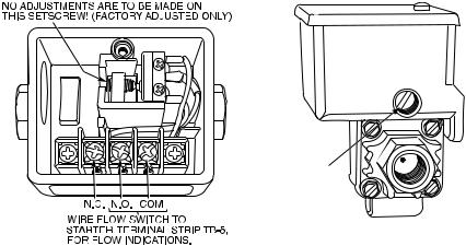
Table 3 Ð Protective Safety Limits and Control Settings
MONITORED PARAMETER |
LIMIT |
APPLICABLE COMMENTS |
|
TEMPERATURE SENSORS |
±40 to 245 F (±40 to 118.3 C) |
Must be outside range for 2 seconds |
|
OUT OF RANGE |
|||
|
|
||
PRESSURE TRANSDUCERS |
|
Must be outside range for 2 seconds. |
|
0.08 to 0.98 Voltage Ratio |
Ratio = Input Voltage ÷ Voltage |
||
OUT OF RANGE |
|||
|
Reference |
||
|
|
||
COMPRESSOR DISCHARGE |
.220 F (104.4 C) |
Preset, alert setting con®gurable |
|
TEMPERATURE |
|||
|
|
||
MOTOR WINDING TEMPERATURE |
.220 F (104.4 C) |
Preset, alert setting con®gurable |
|
BEARING TEMPERATURE |
.185 F (85 C) |
Preset, alert setting con®gurable |
|
|
,33 F (for water chilling) (0.6° C) |
Preset, con®gure chilled medium for |
|
EVAPORATOR REFRIGERANT |
water (Service1 table) |
||
|
|||
|
Con®gure chilled medium for brine |
||
TEMPERATURE |
,Brine Refrigerant Trippoint (set point adjustable |
||
(Service1 table). Adjust brine refrigerant |
|||
|
from 0 to 40 F [±18 to 4 C] for brine chilling) |
||
|
trippoint for proper cutout |
||
|
|
||
TRANSDUCER VOLTAGE |
,4.5 vdc . 5.5 vdc |
Preset |
|
CONDENSER PRESSURE Ð SWITCH |
.263 ± 7 psig (1813 ± 48 kPa), |
Preset |
|
reset at 180 ± 10 (1241 ± 69 kPa) |
|||
|
|
||
Ð CONTROL |
.260 psig (1793 kPa) for HCFC-22; |
Preset |
|
215 psig (1482 kPa) for HFC-134a |
|||
|
|
||
OIL PRESSURE Ð SWITCH |
Cutout ,11 psid (76 kPad) ± 1.5 psid (10.3 kPad) |
Preset, no calibration needed |
|
|
Cut-in .16.5 psid (114 kPad) ± 4 psid (27.5 kPad) |
||
|
|
||
Ð CONTROL |
Cutout ,15 psid (103 kPad) |
Preset |
|
Alert ,18 psid (124 kPad) |
|||
|
|
||
LINE VOLTAGE Ð HIGH |
.110% for one minute |
Preset, based on transformed line volt- |
|
Ð LOW |
|
age to 24 vac rated-input to the Starter |
|
,90% for one minute or <85% for 3 seconds |
|||
Management Module. Also monitored at |
|||
Ð SINGLE-CYCLE |
,50% for one cycle |
PSIO power input. |
|
|
.110% for 30 seconds |
Preset |
|
COMPRESSOR MOTOR LOAD |
,10% with compressor running |
Preset |
|
|
.10% with compressor off |
Preset |
|
STARTER ACCELERATION TIME |
.45 seconds |
For chillers with reduced voltage me- |
|
(Determined by inrush current |
chanical and solid-state starters |
||
|
|||
going below 100% compressor |
.10 seconds |
For chillers with full voltage starters |
|
motor load) |
(Con®gured on Service1 table) |
||
STARTER TRANSITION |
.75 seconds |
Reduced voltage starters only |
|
|
Energizes condenser pump relay if condenser |
|
|
CONDENSER FREEZE |
refrigerant temperature or condenser entering |
CONDENSER FREEZE POINT con®g- |
|
water temperature is below the con®gured con- |
|||
ured in Service01 table with a default |
|||
PROTECTION |
denser freeze point temperature. Deenergizes |
||
setting of 34 F (1 C). |
|||
|
when the temperature is 5 F (3 C) above con- |
||
|
|
||
|
denser freeze point temperature. |
|
|
|
|
|
Flow Switches (Field Supplied)
Operate water pumps with chiller off. Manually reduce water ¯ow and observe switch for proper cutout. Safety shutdown occurs when cutout time exceeds 3 seconds.
CUT-OUT
SETTING
ADJUSTMENT
SCREW
30
 Loading...