


EVERVU™ Touch Screen Display for EVERGREEN® 19XR,XRV, 23XRV Chillers with PIC II or PIC III Controls
Installation and Start-Up Instructions
Part No: 33CNTVIEW
CONTENTS
SAFETY CONSIDERATIONS . . . . . . . . . . . . . . . . . . . . . . 1 INTRODUCTION . . . . . . . . . . . . . . . . . . . . . . . . . . . . . . . . . . 1
ABBREVIATIONS AND EXPLANATIONS . . . . . . . . . . 1
PACKAGE CONTENTS . . . . . . . . . . . . . . . . . . . . . . . . . . . 1
CHILLER SOFTWARE VERSION
REQUIREMENTS . . . . . . . . . . . . . . . . . . . . . . . . . . . . . . . .1,2
INSTALLATION . . . . . . . . . . . . . . . . . . . . . . . . . . . . . . . . . 2-4 Equipment Needed. . . . . . . . . . . . . . . . . . . . . . . . . . . . . . . 2
Step 1 — Identify Power Supply . . . . . . . . . . . . . . . . . . 2 Step 2 — Assemble Swing Arm . . . . . . . . . . . . . . . . . . 2 Step 3 — Attach Arm to Tube Sheet . . . . . . . . . . . . . . 2
Step 4 — Mount Display Screen on Arm
Mounting Bracket . . . . . . . . . . . . . . . . . . . . . . . . . . . . . . . 2
Step 5 — Connect Cable Between Display and ICVC (International Chiller Visual Control) . . . . . . 4
START-UP . . . . . . . . . . . . . . . . . . . . . . . . . . . . . . . . . . . . . 4-10 Start Touch Screen System . . . . . . . . . . . . . . . . . . . . . . 4
Start Carrier Network Manager . . . . . . . . . . . . . . . . . . . 5
Configure ComfortVIEW™ Software on Touch Screen . . . . . . . . . . . . . . . . . . . . . . . . . . . . . . . . . . . . . . . . . . 5
SAFETY CONSIDERATIONS
When installing this accessory, observe precautions in the literature and on any labels attached to the equipment, and all other safety precautions that may apply.
•Follow all safety codes.
•Use care in handling and installing this accessory.
included for all chillers. The display may also be retrofitted to competitor’s chillers when the 32 Series retrofit panels are applied.
ABBREVIATIONS AND EXPLANATIONS
Terms and abbreviations used in this manual include:
CCN (Carrier |
— Carrier’s proprietary communications |
Comfort Network) |
protocol |
CCN bus |
— 3-wire RS-485 network for CCN elements |
CCN element |
— Unique addressing scheme for devices |
|
on a CCN network |
Network Manager — ComfortVIEW software system for |
|
|
managing network devices |
Workspace |
— ComfortVIEW software for managing |
Manager |
viewspaces and trends within |
|
workspaces for graphical representation |
|
of a system |
PACKAGE CONTENTS
•Touch screen display screen with quick connect mount
•Swing arm for mounting (assembly required; see Swing Arm Assembly Instructions)
•RS-232 to RS-485 converter from B&B Electronics
•ComfortVIEW software key (USB) (already installed in back side of display screen)
•Several bags containing bolts and Allen style wrenches
•Touch computer power supply
•6-ft or 25-ft Beldon power cable (25-ft cable will be available for order)
•25-ft coiled communication cable with RJ-14 connectors
•Swing Arm Assembly Instructions
 WARNING
Electrical shock can cause personal injury and death. Shut off all power to this equipment during installation. There may be more than one disconnect switch. Tag all disconnect locations to alert others not to restore power until work is completed.
CHILLER SOFTWARE VERSION REQUIRE-
MENTS
The chiller software in the International Chiller Visual Control (ICVC) controller must match a version of chiller software for which the EverVu workspace screens have been developed. The EverVu display is supplied with databases to support the chiller software versions listed in Table 1.
INTRODUCTION
Carrier's new EverVu™ touch screen display allows a facility manager to monitor a chiller from a 15-in. color touch screen display. The EverVu display screens allow easy navigation to determine data and chiller trends such as a chiller performance trend, chilled water trend, condenser water trend and power trend. The EverVu touch screen display is available for Evergreen 19XR, 19XRV and 23XRV chillers and 32 Series chiller retrofit packages. The display is provided with ComfortVIEW™ software preloaded.
Retrofit Compatibility — The EverVu™ display can be retrofitted to any existing Carrier Comfort Network® (CCN) compatible chiller, though default screen sets may not be
Table 1 — Chiller Software Version Requirements
|
EVERVU DATABASE |
CHILLER |
|
UNIT |
SOFTWARE |
||
VERSION |
|||
|
VERSION |
||
|
|
||
19XR |
19XR Version 09 Chiller |
CESR-131294-09 |
|
19XRV |
19XRV Version 04 Chiller |
CESR-131350-04 |
|
23XRV |
23XRV Version 02 Chiller |
CESR-131293-02 |
|
32DK |
19DK Version 01 Chiller |
CESR-131458-01 |
|
(Build 0.016) |
|||
|
|
||
32XR |
32XR Version 01 Chiller |
CESR-131435-01 |
Manufacturer reserves the right to discontinue, or change at any time, specifications or designs without notice and without incurring obligations.
Catalog No. 04-53190018-01 |
Printed in U.S.A. |
Form 19/23-2SI |
Pg 1 |
6-11 |
Replaces: 19/23-1SI |
If the chiller software is an earlier version than is supported by the EverVu display, the chiller software will need to be upgraded to match the version of EverVu database that will be cloned during the installation of the display.
If the chiller software is a later version than is supported by the EverVu display, a new EverVu database will need to be downloaded and imported into the EverVu display. Contact a Carrier Service office for assistance in importing the databases.
INSTALLATION
Equipment Needed
•3/16 in. hex screwdriver
•1/4 -20-1 in. hex bolts
•Voltmeter
Step 1 — Identify Power Supply
POWER REQUIREMENTS — The EverVu™ panel is provided with a 25-ft Beldon power cable and plug for connection to a 120-v receptacle. If 120-v receptacle is available, proceed to Step 2. If 120-v receptacle is not available, power may be obtained directly from the chiller power panel by following the instruction below.
Connecting Power Cable to Chiller Power Panel — The following instructions are for connecting the power cable of the display panel directly to the 110-v supply at the chiller power panel. If the power cable of the display can be connected to a 120-v receptacle, this step is not necessary; proceed to Step 2.
 WARNING
Electrical shock can cause personal injury and death. Shut off all power to this equipment during installation. There may be more than one disconnect switch. Tag all disconnect locations to alert others not to restore power until work is completed.
1.Identify the oil heater contactor (1C) in the chiller power panel.
2.Using a voltmeter, check the voltage across Terminals 22 and 23. The voltage should be 110 v 10%. If the voltage is not within this range, STOP immediately and consult an appropriate electrical specialist.
3.Using a voltmeter, verify that Terminal 23 in oil heater contractor is neutral. If not, STOP immediately and consult an appropriate electrical specialist.
4.After verifying voltages in Steps 2 and 3, turn off chiller power and verify that the oil heater contractor is deenergized and no voltage is present at the input Terminals 22 and 23.
5.LOCK OUT and TAG OUT power supply to the chiller power panel.
6.Remove the plug of the display panel power cord with a wire cutter.
7.Strip approximately 6 in. of insulation off power cable end.
8.Using two fork connectors (red and blue), crimp according to the following color code:
a.WHITE wire to RED connector
b.BLACK wire to BLUE connector.
9.Strip the insulation off the green grounding wire.
10.Remove the electrical knockout from the panel and add a strain relief connection, if necessary.
11.Pulls the wires through strain relief and connect the green grounding wire to the grounding lug. Connect
the fork terminals to the input of the oil heater circuit breaker as follows:
a.1C-22 to RED fork terminal (WHITE wire)
b.1C-23 to BLUE fork terminal (BLACK wire).
12.For safety reasons, do not remove LOCK OUT and TAG OUT until completing Step 5 — Connect Cable Between Display and ICVC (International Chiller Visual Control).
Step 2 — Assemble Swing Arm — Refer to separate Swing Arm Assembly Instructions provided in package.
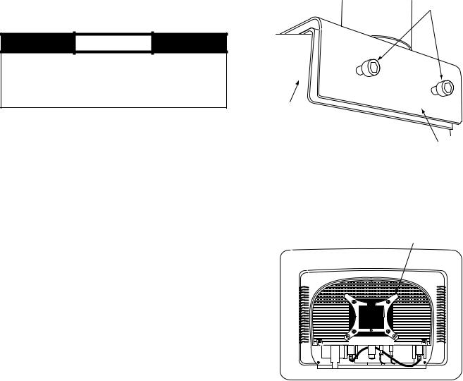
Step 3 — Attach Arm to Tube Sheet
1.Identify the tube sheet on the evaporator (19XR,XRV) or condenser (23XRV) where the display is to be mounted. Insert the bolt into the center hole of the tube sheet mounting bracket.
NOTE: Do not remove the white plastic piece inside the mounting bracket. This serves to insulate the metal between the tube sheet and mounting bracket.
2.Attach the 1/4 -20-1 in. hex bolts halfway through in the base of the mounting bracket. Do not tighten completely.
3.Align the arm mounting bracket to the tube sheet and tighten hex bolts using a 3/16 hex screwdriver. See Fig. 1.
MOUNTING
BOLTS
TUBE
SHEET
a19-1891
ARM BASE
Fig. 1 — Attach Arm to Tube Sheet
Step 4 — Mount Display Screen on Arm
Mounting Bracket — Locate the EverVu display panel. Do not remove the plastic covering until you are ready to start up the touch screen. The display screen is shipped with the quick connect mount attached to the back of the screen. See Fig. 2.
DISPLAY MOUNT
a19-1890
BACK OF DISPLAY PANEL
Fig. 2 — Display Panel with Mount Attached
2

1.Slide the screen display onto the mounting bracket. (location shown in Fig. 3).
 a19-1892
MOUNTING
BRACKET
Fig. 3 — Display Screen Mounting Location
2.Two hooks secure the display screen to the mounting bracket. Hold the display screen until verifying that the display screen is supported by the hooks on the mounting bracket before releasing. See Fig. 4.
IMPORTANT: To prevent damage to display screen, do not mount the display on the arm until arm is completely attached to the tube sheet.
MOUNTING
BRACKET
DISPLAY
MOUNT a19-1893 RETAINING BOLT
Fig. 4 — Bolt Display Screen to Arm
3.The display height is adjustable within a 15.9 in. range. Arm dimensions are shown in Fig. 5.
4.Using a hex screwdriver, secure the arm from pulling out of the mount by tightening the hex screw on the side of the mount. The display screen can now be positioned to desired height. To adjust tension on the up and down movement of the arm, tighten the hex screw on the top of the arm mount (Fig. 6).
3.1"
6.7"
MAX |
3.5" |
HORIZONTAL |
|
RANGE |
|
24.1" |
15.3" |
|
13.3"
MAX
VERTICAL
RANGE 15.9"

 7.1" 5.6"

a19-1894
Fig. 5 — Display Arm Dimensions
HEX SCREW TO
ADJUST ARM
TENSION
ARM
HEX SCREW
TO SECURE
ARM TO ARM
BASE
a19-
1891
Fig. 6 — Adjust Arm Tension
3
Step 5 — Connect Cable Between Display and ICVC (International Chiller Visual Control)
1.Remove the knockout from the control panel box.
2.Pass the 25-ft coiled RS-485 cable, through the knockout. Approximately 16 to 20 in. of cable should be inserted into the control box.
3.Connect one end of the RS-485 cable to the J8/SERVICE port of the ICVC.
4.Connect the other end of the cable to the RJ14 connector in the B&B Electronics converter provided with the display. The converter should then be attached to the 9-pin serial port on the display. If chiller is connected to a CCN network, see note below.
5.The ComfortVIEW™ software key is already installed in the back side of the display. The software key will allow preloaded software to run automatically when the display screen is booted up.
6.After connecting both cable ends, connect the power cord to the power brick and connect to the EverVu™ panel. Pull the cord through the side of the back cover and attach to the display.
7.If touch screen power cord was connected directly to the chiller power panel rather than an AC outlet, remove LOCK OUT and TAG OUT.
8.Turn on power to the display screen (lower right side) and to the ICVC.
Before going to the job site to perform the installation, you will need to know the chiller ICVC version. Some older versions need to be updated to work with the touch panel. Contact a Carrier Service office for assistance in downloading a new version, if required.
NOTE: Besides being connected to the display, the chiller may be on a CCN network in the building. If this is the case, make sure the correct wiring is utilized and coordinate with the Carrier controls technician on the site. The refresh rate of the touch screen display may need to be extended, depending on the other devices on the network.
COMMUNICATION BUS WIRE SPECIFICATIONS — The communication bus wiring is field-supplied and fieldinstalled. Bus wiring consists of shielded three-conductor cable
with drain (ground) wire. The cable selected must be identical to the communication bus wire used for the entire network. See Table 2 for recommended cable.
Table 2 — Recommended Cables
MANUFACTURER |
CABLE PART NO |
Alpha |
2413 or 5463 |
American |
A22503 |
Beiden |
8772 |
Columbia |
02525 |
NOTE: Conductors and drain wire must be at least 20 AWG (American Wire Gage), stranded, and tinned copper. Individual conductors must be insulated with PVC, PVC/nylon, vinyl, Teflon*, or polyethylene. An aluminum/polyester 100% foil shield and an outer jacket of PVC, PVC/nylon, chrome vinyl or Teflon with aluminum operating temperature range of –20 C to 60 C is required.
START-UP
Start Touch Screen System — Once the ICVC and display screen are powered up, the Touch Screen display will boot up to a default graphical chiller for a Version 04XRV. The CCN database for this display is defaulted to database only, so there will be no communications.
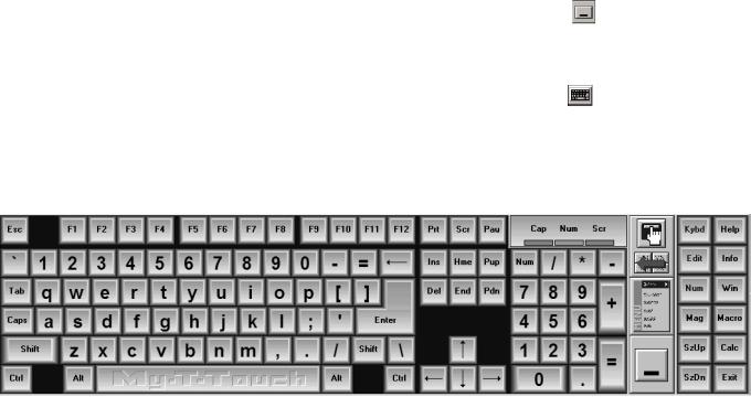
An expandable keyboard (Fig. 7) is viewable after boot up. The keyboard is used for inputting data into any menu screen or prompt that is the active.
The keyboard can be minimized to an icon again by pressing the large rectangular icon on the left side of the expandable keyboard.
The keyboard can be viewed at any time by pressing the keyboard icon at the top right side of any active screen or prompt.
The expandable keyboard can be moved to different positions on the screen be touching any of the blue areas between the keys and moving it to desired position on screen.
a19-1898
Fig. 7 — Expandable Keyboard
*Registered trademark of DuPont.
4
 Loading...