


19XRV
Table of contents
 Loading...
19XRV, 23XRV
with PIC III/PIC 6 Controls
Rockwell PowerFlex 755 VFD Option
Start-Up and Service Instructions
SAFETY CONSIDERATIONS
Centrifugal and screw compressor liquid chillers are designed to
provide safe and reliable service when operated within design
specifications. When operating this equipment, use good judgment and safety precautions to avoid damage to equipment and
property or injury to personnel.
Be sure you understand and follow the procedures and safety precautions contained in the chiller instructions as well as those listed
in this guide.
DANGER
Failure to follow these procedures will result in severe personal
injury or death.
ONLY QUALIFIED electrical personnel familiar with the
construction and operation of this equipment and the hazards
involved should install, adjust, operate, or service this equipment.
READ AND UNDERSTAND this manual and other applicable manuals in their entirety before proceeding. Failure to observe this precaution could result in severe bodily injury or loss
of life.
DO NOT install modification kits with power applied to the
drive. Disconnect and lock out incoming power before attempting such installation or removal. Failure to observe this
precaution could result in severe bodily injury or loss of life.
UNUSED WIRES in conduit must be grounded at both ends to
avoid a possible shock hazard caused by induced voltages. Also, if a drive sharing a conduit is being serviced or installed, all
drives using this conduit should be disabled to eliminate the
possible shock hazard from cross-coupled motor leads. Failure
to observe these precautions could result in bodily injury.
DO NOT VENT refrigerant relief valves within a building.
Outlet from rupture disc or relief valve must be vented outdoors in accordance with the latest edition of ANSI/
ASHRAE 15 (American National Standards Institute/American Society of Heating, Refrigerating, and Air-Conditioning
Engineers). The accumulation of refrigerant in an enclosed
space can displace oxygen and cause asphyxiation.
PROVIDE adequate ventilation in accordance with ANSI/
ASHRAE 15, especially for enclosed and low overhead spaces. Inhalation of high concentrations of vapor is harmful and
may cause heart irregularities, unconsciousness, or death. Misuse can be fatal. Vapor is heavier than air and reduces the
amount of oxygen available for breathing. Product causes eye
and skin irritation. Decomposition products are hazardous.
DO NOT USE OXYGEN to purge lines or to pressurize a
chiller for any purpose. Oxygen gas reacts violently with oil,
grease, and other common substances.
(Dangers continued in next column.)
DANGER
NEVER EXCEED specified test pressures. VERIFY the allowable test pressure by checking the instruction literature and
the design pressures on the equipment nameplate.
DO NOT USE air for leak testing. Use only refrigerant or dry
nitrogen.
DO NOT VALVE OFF any safety device.
BE SURE that all pressure relief devices are properly installed
and functioning before operating any chiller.
THERE IS A RISK OF INJURY OR DEATH by electrocu-
tion. High voltage may be present on the motor leads even
though the motor is not running. Open the power supply disconnect before touching motor leads or terminals.
WARNING
Failure to follow these procedures may result in personal injury or death.
DO NOT USE TORCH to remove any component. System
contains oil and refrigerant under pressure.
To remove a component, wear protective gloves and goggles
and proceed as follows:
a. Shut off electrical power to unit.
b. Recover refrigerant to relieve all pressure from system
using both high-pressure and low-pressure ports.
c. Traces of vapor should be displaced with nitrogen and
the work area should be well ventilated. Refrigerant in
contact with an open flame produces toxic gases.
d. Cut component connection tubing with tubing cutter and
remove component from unit. Use a pan to catch any oil
that may come out of the lines and as a gage for how
much oil to add to the system.
e. Carefully unsweat remaining tubing stubs when neces-
sary. Oil can ignite when exposed to torch flame.
DO NOT work on high-voltage equipment unless you are a
qualified electrician.
DO NOT WORK ON electrical components, including control
panels, switches, VFD, or oil heater until you are sure ALL
POWER IS OFF and no residual voltage can leak from capacitors or solid-state components.
LOCK OPEN AND TAG electrical circuits during servicing.
IF WORK IS INTERRUPTED, confirm that all circuits are
de-energized before resuming work.
AVOID SPILLING liquid refrigerant on skin or getting it into
the eyes. USE SAFETY GOGGLES. Wash any spills from
the skin with soap and water. If liquid refrigerant enters the
eyes, IMMEDIATELY FLUSH EYES with water and consult a physician.
(Warnings continued on next page.)
Catalog No. 04-53190061-01 Printed in U.S.A. Form 19/23-8SS Pg 1 6-19 Replaces: 19/23-7SS
Manufacturer reserves the right to discontinue, or change at any time, specifications or designs without notice and without incurring obligations.
WARNING
DO NOT ATTEMPT TO REMOVE fittings, covers, etc.,
while chiller is under pressure or while chiller is running. Be
sure pressure is at 0 psig (0 kPa) before breaking any refrigerant connection.
CAUTION
Failure to follow these procedures may result in personal injury or damage to equipment.
TO AVOID an electric shock hazard, verify that the voltage on
the bus capacitors has discharged completely before servicing.
Check the DC bus voltage at the power terminal block by measuring between the +DC and -DC terminals, between the +DC
terminal and the chassis, and between the -DC terminal and the
chassis. The voltage must be zero for all 3 measurements.
THE USER is responsible to conform with all applicable local,
national, and international codes. Failure to observe this precaution could result in damage to, or destruction of, the equipment.
THIS DRIVE contains ESD (electrostatic discharge) sensitive
parts and assemblies. Static control precautions are required
when installing, testing, servicing or repairing this assembly.
Component damage may result if ESD control procedures are
not followed. For static control procedures, reference Rockwell publication Guarding Against Electrostatic Damage, or
any other applicable ESD protection handbook.
DO NOT alter the setting of any jumper. Failure to observe
this precaution could result in damage to, or destruction of, the
equipment.
USE OF power correction capacitors on the output of the drive
can result in erratic operation of the motor, nuisance tripping,
and/or permanent damage to the drive. Remove power correction capacitors before proceeding. Failure to observe this precaution could result in damage to, or destruction of, the equipment.
MOST CODES require that upstream branch circuit protection
be provided to protect input power wiring. If fuses are chosen
as the protection method, refer to the PowerFlex 750 user manual. Failure to observe this precaution could result in damage
to, or destruction of, the equipment.
DO NOT route signal and control wiring with power wiring in
the same conduit. This can cause interference with drive operation. Failure to observe this precaution could result in damage
to, or destruction of, the equipment.
DISTRIBUTION SYSTEM short circuit capacity shall not exceed the rating of the drive. Failure to observe this precaution
could result in damage to, or destruction of, the equipment.
DO NOT STEP on refrigerant lines. Broken lines can whip
about and release refrigerant, causing personal injury.
DO NOT climb over a chiller. Use platform, catwalk, or staging. Follow safe practices when using ladders.
USE MECHANICAL EQUIPMENT (crane, hoist, etc.) to lift
or move inspection covers or other heavy components. Even if
components are light, use mechanical equipment when there is
a risk of slipping or losing your balance.
BE AWARE that certain automatic start arrangements CAN
ENGAGE THE VFD, TOWER FAN, OR PUMPS. Open the
disconnect ahead of the VFD, tower fans, or pumps.
(Cautions continued in next column.)
CAUTION
USE only repair or replacement parts that meet the code requirements of the original equipment.
PERIODICALLY INSPECT all valves, fittings, and piping for
corrosion, rust, leaks, or damage.
DO NOT re-use compressor oil or any oil that has been exposed to the atmosphere. Dispose of oil per local codes and
regulations.
DO NOT leave refrigerant system open to air any longer than
the actual time required to service the equipment. Seal circuits
being serviced and charge with dry nitrogen to prevent oil contamination when timely repairs cannot be completed.
CONTENTS
Page
SAFETY CONSIDERATIONS . . . . . . . . . . . . . . . . . . . . . . . . 1
INTRODUCTION . . . . . . . . . . . . . . . . . . . . . . . . . . . . . . . . . . . . 2
ABBREVIATIONS AND EXPLANATIONS. . . . . . . . . . . . 3
Required Publications. . . . . . . . . . . . . . . . . . . . . . . . . . . . . . 3
Getting Assistance from Rockwell Automation. . . . . 3
IDENTIFYING DRIVE COMPONENTS . . . . . . . . . . . . . . . 3
Opening the VFD Access Door . . . . . . . . . . . . . . . . . . . . . 3
Drive Assembly Catalog Number . . . . . . . . . . . . . . . . . . . 3
Components and Physical Data . . . . . . . . . . . . . . . . . . . . 4
START-UP. . . . . . . . . . . . . . . . . . . . . . . . . . . . . . . . . . . . . . . . . . 7
Alternate Wire Lugs . . . . . . . . . . . . . . . . . . . . . . . . . . . . . . . . 7
Verify Installation . . . . . . . . . . . . . . . . . . . . . . . . . . . . . . . . . . 7
Configure the VFD. . . . . . . . . . . . . . . . . . . . . . . . . . . . . . . . . . 8
Commissioning the Unit. . . . . . . . . . . . . . . . . . . . . . . . . . . . 9
Check Internal Jumpers . . . . . . . . . . . . . . . . . . . . . . . . . . . . 9
SERVICE . . . . . . . . . . . . . . . . . . . . . . . . . . . . . . . . . . . . . . . . . . 10
Troubleshooting the Drive. . . . . . . . . . . . . . . . . . . . . . . . . 10
• CHILLER ALERT CODES
• CHILLER ALARM CODES
• TEST EQUIPMENT NEEDED TO TROUBLESHOOT
• VERIFYING THAT DC BUS CAPACITORS ARE
DISCHARGED
• HIGH TEMPERATURE ALARMS
• MAIN CONTROL BOARD (MCB) COMPONENTS
Checking Power Modules and Motor Input
with Input Power Off . . . . . . . . . . . . . . . . . . . . . . . . . . . . 14
Servicing the Drive . . . . . . . . . . . . . . . . . . . . . . . . . . . . . . . . 15
• REMOVING THE DRIVE
• RIGGING THE ENCLOSURE
• REPLACING THE GATEWAY
• CHILL PLATE FAN AND INTERNAL FAN REPLACEMENT
Part Identification and Location . . . . . . . . . . . . . . . . . . . 18
APPENDIX A — WIRING SCHEMATICS . . . . . . . . . . . 21
INTRODUCTION
The Carrier VFD option Start-Up and Service Manual is intended
for trained and qualified service personnel and is to be used during
start-up, operation, and maintenance of Rockwell/Allen-Bradley
PF755L drive.
2
ABBREVIATIONS AND EXPLANATIONS
ID No.: 21P-104773-40
Input Rating: 480VAC 454A 60Hz 3PH
Output Rating: 0-460VAC 477A 0-325Hz 3PH
Short Circuit Rating: 65kA, 480V Max.
Interrupt Capacity Rating: 100kAIC
Enclosure Type: TYPE 1
Coolant Type: Refrigerant R134a
Design Pressure: 185 PSIG
Carrier Part Number: 19XVR0445335A1F
VFD Serial Number: XXXXXXXXX
Carrier Dwg. Number: 19XV04021001
Mfd. On: 08-13-10
FAC.LOC.: 1100
Max. Ambient Temperature: 40°C
ORDER NO: 0001772838-00001
1
L1 L2 L3
O
I
2
DC+ DC–
0V
0V
LOCKOUT/TAGOUT
MULTIMETER
DC BUS TEST
TERMINALS
LOCATED INSIDE
ACCESS DOOR
Frequently used abbreviations in this manual include:
CCM — Chiller Control Module
DC — Direct Current
DPI — Drive Peripheral Interface
ENET — Ethernet
HMI — Human Machine Interface
ICVC — International Chiller Visual Controller
IGBT — Insulated Gate Bipolar Transistor
I/O — Inputs/Outputs
IP — Internet Protocol
MCB — Main Control Board
MOV — Metal Oxide Varistor
PE — Protective Earthing Conductor
PIC — Product Integrated Control
PWM — Pulse Width Modulation
SIO — Sensor Input/Output
STS — Status
VFD — Variable Frequency Drive
Required Publications
The Carrier VFD option Start-Up and Service Manual must be
used with the following manuals:
• Latest version of the PowerFlex 755 AC Drives manuals
• Latest revision of the Start-Up, Operation, and Maintenance Instructions for the 19XRV or 23XRV with PIC III
Controls
Getting Assistance from Rockwell Automation
Contact the local Rockwell Automation sales office with any
questions or problems relating to the products described in this
manual. For technical support on drives, call the HVAC Hotline at
1-888-926-6786, Option 1.
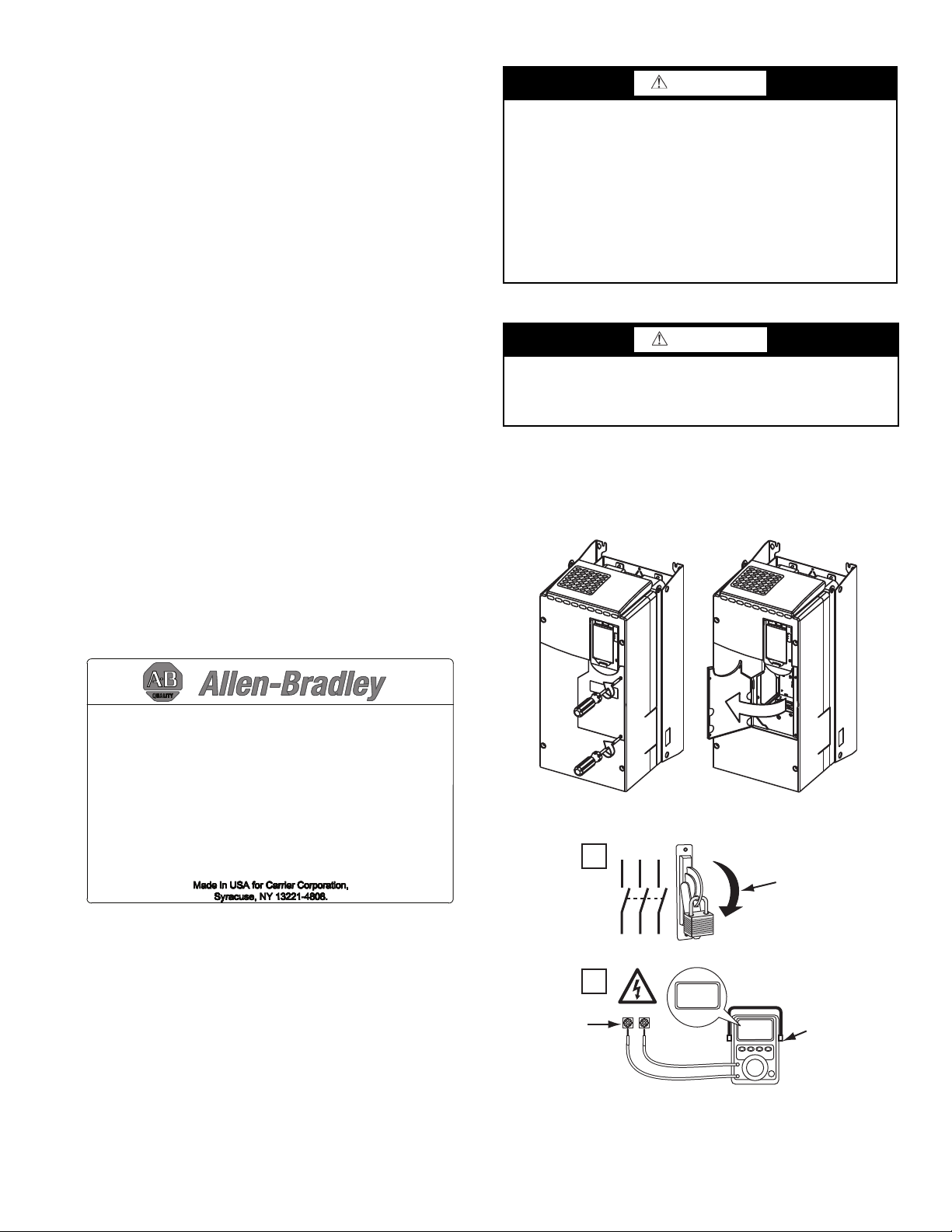
Before calling, have the following information available from the
Allen-Bradley data nameplate located inside the enclosure on the
right wall. See Fig. 1.
• Allen-Bradley ID or CAT. NO.
• Carrier VFD Code (Carrier Part Number)
• Allen-Bradley serial number
WARNING
DC bus capacitors retain hazardous voltages after input power
has been disconnected. After disconnecting input power, wait
five (5) minutes for the DC bus capacitors to discharge and
then check the voltage with a voltmeter rated for the DC bus
voltage to ensure the DC bus capacitors are discharged before
touching any internal components. Failure to observe this precaution could result in severe bodily injury or loss of life.
An isolated multimeter will be needed to measure DC bus voltage and to make resistance checks. The drive’s DC bus capacitors retain hazardous voltages after input power has been disconnected.
Opening the VFD Access Door
WARNING
Before removing the drive enclosure, open access door and
verify that the DC bus voltage has dropped to zero by checking
the terminals behind the access door. Failure to observe this
precaution could result in severe bodily injury or loss of life.
1. Using recommended screwdriver (6.4 mm [0.25 in.] flat or
T20 star), open access door. See Fig. 2.
2. Check to be sure that the voltage between DC+ and DC–
and from each DC terminal to the chassis is zero before
proceeding. See Fig. 3.
Fig. 1 — Allen Bradley Data Nameplate
IDENTIFYING DRIVE COMPONENTS
Chiller control schematics and VFD schematics are included in
Appendix A.
Fig. 2 — Opening Access Door
Fig. 3 — Check DC Bus Terminals
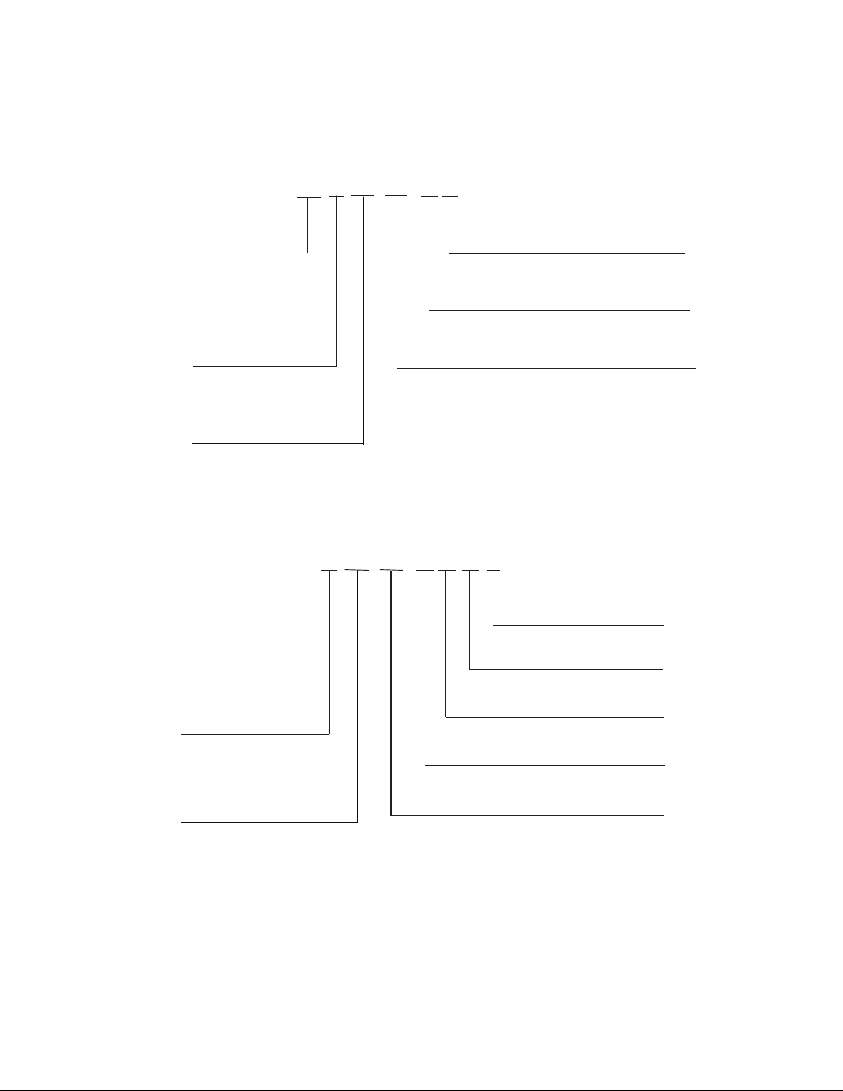
Drive Assembly Catalog Number
See Fig. 4 and 5 for examples of the Rockwell Automation Drive
Assembly Catalog Number.
3
Components and Physical Data
* For Carrier applications, maximum continuous amp ratings
are 230, 335, and 445.
* For Carrier applications, maximum continuous amp ratings are 230, 269, 335, and 445.
† For 600 v applications, CB1 = 65 KAIC and CB2 = 42 KAIC rating (575 v).
21PB -
1 0248
-
3 0
21PB - 23XRV Std Tier
Voltage Code
1 – 480 vac, 60 Hz
2 – 380 vac, 50 Hz
3 – 380 vac, 60 Hz
4 – 400 vac, 50 Hz
6 – 415 vac, 50 Hz
7 – 415 vac, 60 Hz
8 – 600 vac, 60 Hz
Full Load Amp Rating
(Maximum Continuous Amps)*
0248 – 248
0289 – 289
0361 – 361
0477 – 477
4
Enclosure
1 – Unit Mount Type 1/IP23 Air Cooled/Filter
4 – Unit Mount Type 1/IP23 Liquid Cooled
Input Device
3 – 65 KAIC Capacity Breaker
4 – 100 KAIC Capacity Breaker
†
Meter Option
0 – No Meters
2 – Digital Meter
a19-2381
0
Control Power
0 – Standard
1 – High
0
CE (Conformité Européenne)
0 – No
1 – Ye s
The 19XRV chillers use the Allen-Bradley PF755 Frame 6 drive
for the 230-amp rated application (Carrier Part No.
19XVR0230...). See Fig. 6.
The Allen-Bradley PF755 Frame 7 drive is used for the 335-amp
and 445-amp rated application (Carrier Part No. 19XVR0335...
and 19XVR0445...). See Fig. 7.
1 0248
21P -
21P - 19XRV Std Tier
Voltage Code
1 – 480 vac, 60 Hz
2 – 380 vac, 50 Hz
3 – 380 vac, 60 Hz
4 – 400 vac, 50 Hz
5 – 400 vac, 60 Hz
6 – 415 vac, 50 Hz
7 – 415 vac, 60 Hz
Full Load Amp Rating
(Maximum Continuous Amps)*
0248 – 248
0361 – 361
0477 – 477
See Fig. 8 for the dimensions of Frames 6 and 7 for 19XRV
chillers.
The 23XRV chiller uses the Frame 7 drive for 335-amp and 455amp rated applications (Carrier Part No. 23XVR0335... and
23XVR0445...). Frame 6 is not used.
See Fig. 9 for the dimensions of Frame 7 for 23XRV chillers.
-
3 0
5
Meter Option
0 – No Meters
2 – Digital Meter
Input Device
3 – 65 KAIC Capacity Breaker
4 – 100 KAIC Capacity Breaker
Enclosure
4 – Unit Mount Type 1/IP23 Liquid Cooled
5 – Unit Mount Type 1/IP23 Liquid Cooled/Air Filter
a19-2380
Fig. 4 — Rockwell Automation Drive Assembly Catalog Number Nomenclature: 19XRV Units
Fig. 5 — Rockwell Automation Drive Assembly Catalog Number Nomenclature: 23XRV Units
4
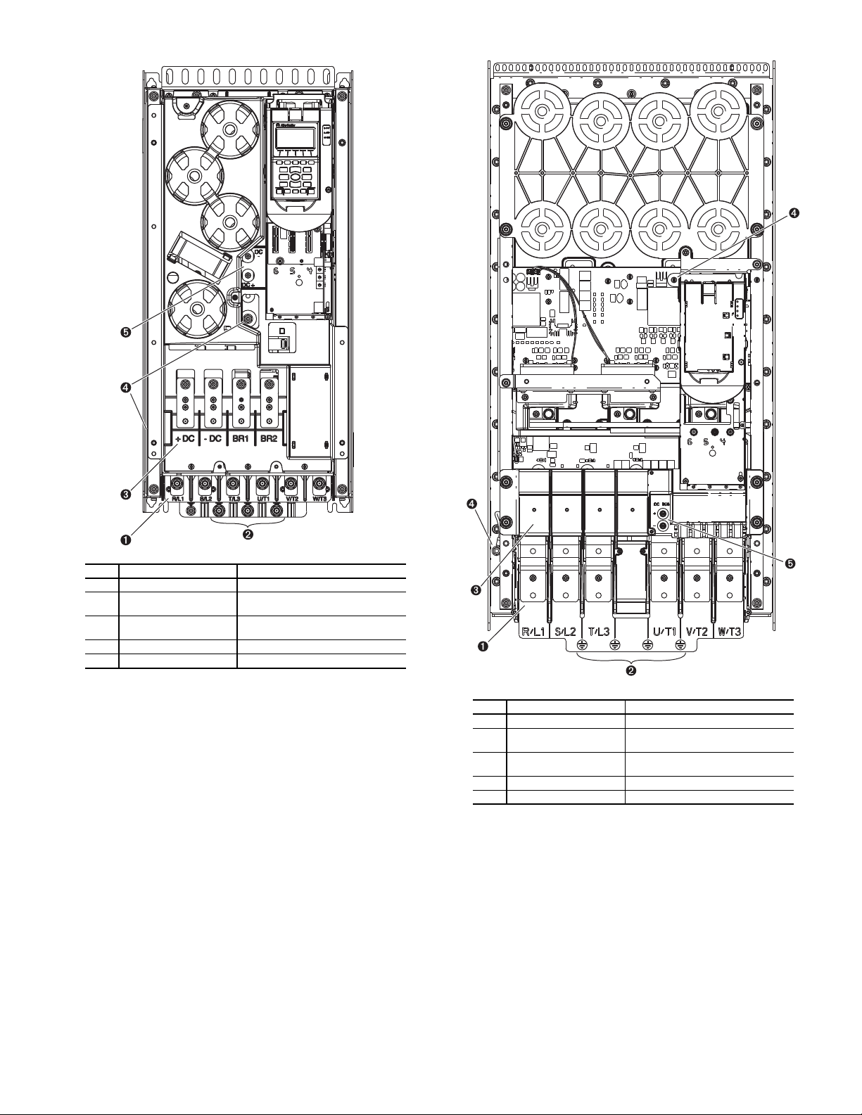
Fig. 6 — Frame 6 Drive Components
LEGEND
NO. NAME DESCRIPTION
1 Power Terminals R/L1, S/L2, T/L3, U/T1, V/T2, W/T3
2
PE Grounding Studs Terminating point to chassis ground
for incoming motor shield
3
DC Bus and Brake
Terminals
+DC, -DC, BR1, BR2
4 PE-A and PE-B MOV and CMC Jumper Wires
5 DC+ and DC- Bus Voltage Test Points
LEGEND
NO. NAME DESCRIPTION
1 Power Terminals R/L1, S/L2, T/L3, U/T1, V/T2, W/T3
2
PE Grounding Studs Terminating point to chassis ground
for incoming motor shield
3
DC Bus and Brake
Terminals
+DC, -DC, BR1, BR2
4 PE-A and PE-B MOV and CMC Jumper Wires
5 DC+ and DC- Bus Voltage Test Points
Fig. 7 — Frame 7 Drive Components
5
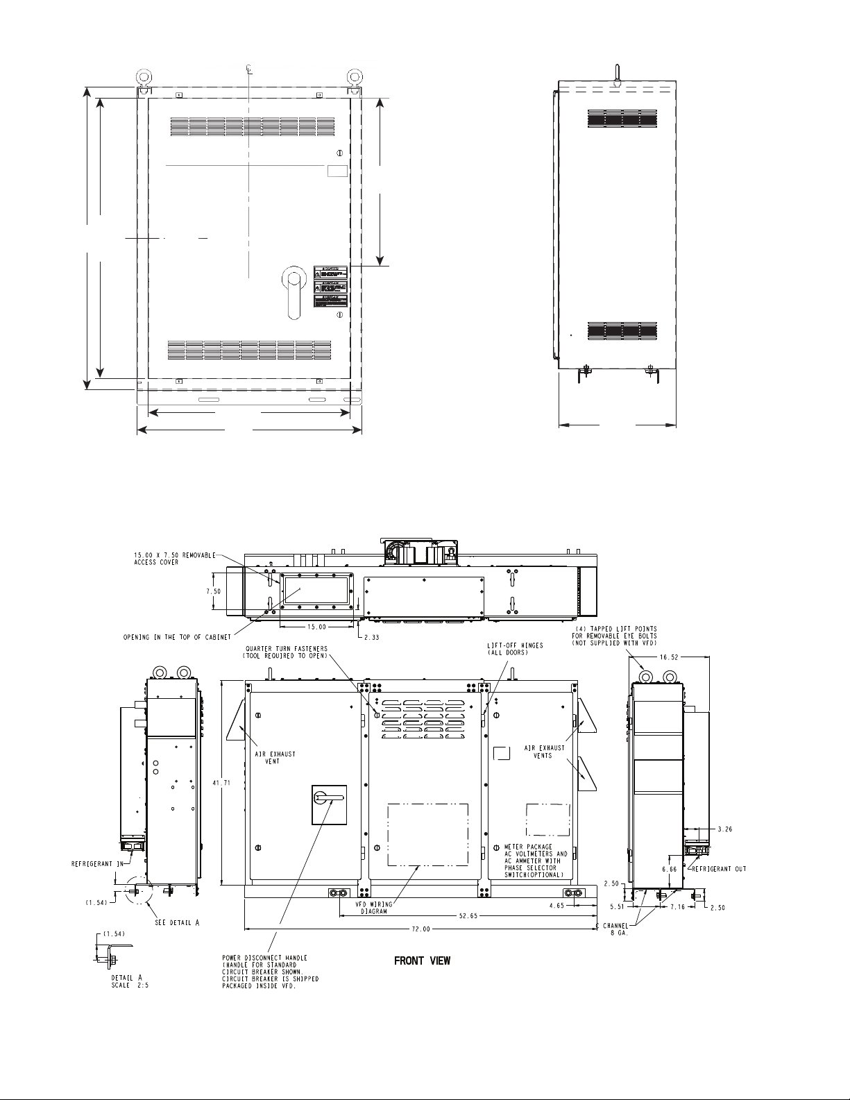
C
L
50.00 REF
54.00
36.00 REF
40.00
FRONT VIEW
C
L
30.00
22.00
a19-2379
SIDE VIEW
NOTE: Dimensions shown in inches.
a19-2011
NOTE: Dimensions shown in inches.
Fig. 8 — 19XRV Enclosure Dimensions — Frames 6 and 7
Fig. 9 — 23XRV Enclosure Dimensions — Frame 7
6
START-UP Alternate Wire Lugs
DANGER
Internal components and circuit boards of the drive are live
when the drive is connected to incoming power. Coming into
contact with this voltage is extremely dangerous and will result
in severe personal injury or death.
The motor terminals U, V, W and the DC-link/brake resistor
terminals B+/R+, R- are live when the drive is connected to incoming power, even if the motor is not running.
Do not make any connections when the drive is connected to
the incoming power.
After having disconnected the drive, wait until the indicators
on the keypad go out (if no keypad is attached see the indicator
through the keypad base). Wait 5 more minutes before doing
any work on drive connections. Do not even open the cover
before this time has expired.
Before connecting the drive to the incoming power, make sure
that the switchgear enclosure door is closed.
WARNING
The control I/O-terminals are isolated from the mains potential. However, the relay outputs and other I/O terminals may
have a dangerous control voltage present even when the drive
is disconnected from incoming power. Coming into contact
with this voltage could result in severe personal injury.
CAUTION
If other than refrigerant cooling is used, before connecting the
drive to the incoming power, make sure that the coolant is circulating and has no leaks.
If the incoming power wire size does not fit the standard lug, alternate lugs may be used. See Table 1. Note that lugs rated for a higher current than the circuit breaker may be used.
Verify Installation
Record the following job information:
1. Job Name
2. Job Number
3. City
4. State
5. Zip Code
Record the following nameplate information:
1. From the Allen-Bradley nameplate (Fig. 1) located inside
the VFD enclosure:
a. Allen-Bradley ID or CAT NO.
b. Allen-Bradley Serial Number
c. Carrier Part Number
2. From the machine nameplate (Fig. 10) located inside the
VFD enclosure:
a. Chiller Serial Number
b. Chiller Model
c. Motor rated load amps
d. Motor nameplate rpm
e. Motor nameplate kW
f. Motor nameplate voltage
g. Inverter PWM (pulse width modulation) frequency
h. Voltage
3. From the drive module label (Fig. 11) located on the drive
module:
a. Model or Cat. Number
b. Serial Number
4. From the HMI control panel screen:
a. Carrier Part Number and Revision
b. Software Number
CAUTION
When working with the Drive Explorer, never use the Rotate
function as the motor will immediately start and severe compressor damage could result.
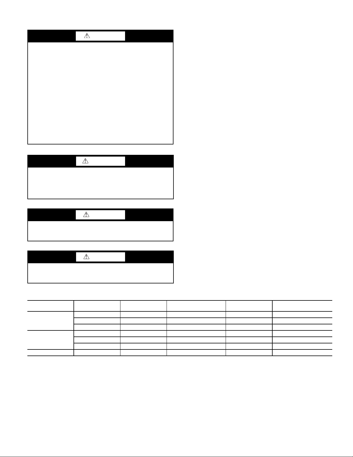
Table 1 — Wire Lugs
VOLTAGE
480
380/400/415
600 269 KT5300 (1) 250 - 500 MCM KT5400 (2) 3/0 - 250 MCM
CARRIER VFD MAX
INPUT AMPS
230 KT5300 (1) 250 - 500 MCM KT5400 (2) 3/0 - 250 MCM
335 K6TJ (3) 2/0 - 400 MCM K6TH (2) 250 - 500 MCM
445 K6TJ (3) 2/0 - 400 MCM K6TH (2) 250 - 500 MCM
230 KT5400 (2) 3/0 - 250 MCM KT5300 (1) 250 - 500 MCM
335 K6TJ (3) 2/0 - 400 MCM K6TH (2) 250 - 500 MCM
445 K6TJ (3) 2/0 - 400 MCM K6TH (2) 250 - 500 MCM
STANDARD
ABB LUG
STANDARD LUG
CABLE RANGE
ALTERNATE
ABB LUG
ALTERNATE LUG
CABLE RANGE
7
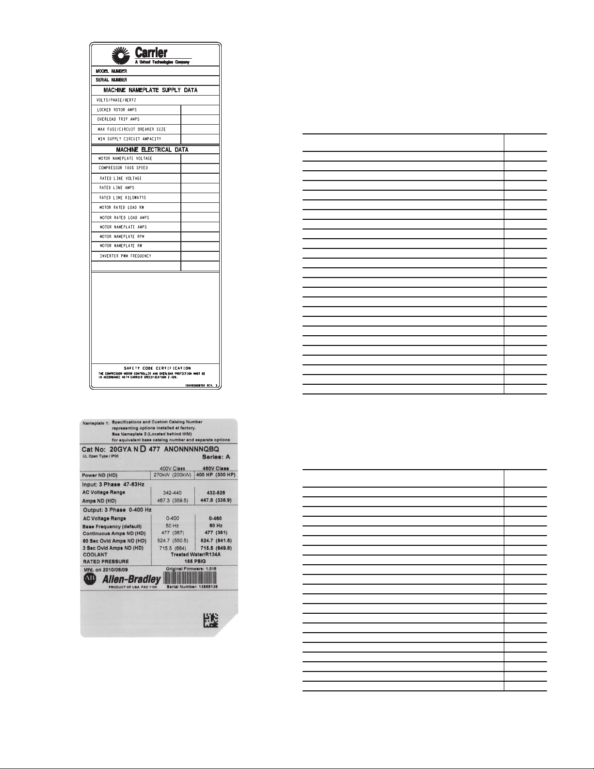
Fig. 10 — Machine Nameplate
Fig. 11 — Drive Module Label
Configure the VFD
All configurations required by the VFD are supplied by the HMI
through the VFD Gateway. The 19XRV, 23XRV Std Tier VFD
can operate with PIC III and PIC 6. Any configuration changes
necessary and possible are made on the HMI screens. A complete
set of configurations is transmitted to the VFD each time the controls are powered up.
Table 2 lists parameters displayed on the 19XRV, 23XRV PIC3/
VFD_CONF screen. Table 3 shows parameters in the Unit
Mounted VFD Configuration menu for PIC6. Parameters in ital-
ics are to be entered or confirmed at start-up. Parameters in bold
are to be changed only after consulting with Carrier service engineering.
Table 2 — VFD Configurations (PIC3/VFD_CONF)
PARAMETER
MOTOR NAMEPLATE VOLTAGE 460
COMPRESSOR 100% SPEED
LINE FREQ=60 HZ? (NO=50) YES
RATED LINE VOLTAGE* 460
RATED LINE AMPS* † 200
RATED LINE KILOWATTS* 100
MOTOR RATED LOAD KW 100
MOTOR RATED LOAD AMPS 200
MOTOR NAMEPLATE AMPS 100
MOTOR NAMEPLATE RPM 3456
MOTOR NAMEPLATE KW 100
INVERTER PWM FREQUENCY (0 = 4 KHZ, 1 = 2 KHZ) 1
SKIP FREQUENCY 1 (HZ) 20.0
SKIP FREQUENCY 2 (HZ) 20.0
SKIP FREQUENCY 3 (HZ) 20.0
SKIP FREQUENCY BAND LINE (HZ) 0.0
VOLTAGE % IMBALANCE 10
LINE VOLT IMBALANCE TIME (SEC) 10
LINE CURRENT % IMBALANCE 40
LINE CURRENT IMBAL TIME (SEC) 10
MOTOR CURRENT % IMBALANCE 40
MOTOR CURRENT IMBAL TIME 10
INCREASE RAMP TIME (SEC) 30
DECREASE RAMP TIME (SEC) 30
SINGLE CYCLE DROPOUT (DSABLE/ENABLE) DSABLE
* Parameters marked with an * are not downloadable to the VFD but are used in
other calculations and algorithms in the ICVC.
NOTES:
1. Parameters in italics are to be entered or confirmed at start-up.
2. Parameters in bold are to be changed only after consultation with service
engineering.
DEFAULT
VALUE
Table 3 — VFD Configuration (PIC6/UM VFD
Configuration) CFGUMVFD - UM VFD Configuration
PARAMETER
COMPRESSOR 100% SPEED 60
RATED LINE VOLTAGE* 460
MOTOR NAMEPLATE CURRENT 200
MOTOR RATED LOAD CURRENT 200
MOTOR NAMEPLATE VOLTAGE 460
MOTOR NAMEPLATE RPM 3000
MOTOR NAMEPLATE KW 1500
SKIP FREQUENCY 1 30
SKIP FREQUENCY 2 30
SKIP FREQUENCY 3 30
SKIP FREQUENCY BAND 0
INCREASE RAMP TIME 30
DECREASE RAMP TIME 30
LINE VOLTAGE IMBALANCE% 10
LINE VOLT IMBALANCE TIME 10
LINE CURRENT IMBALANCE% 40
LINE CURRENT IMBAL TIME 10
MOTOR CURRENT IMBALANCE% 40
MOTOR CURRENT IMBAL TIME 10
SINGLE CYCLE DROPOUT DISABLE
PWM SWITCH FREQUENCY (0=2 KHZ, 1=4 KHZ) 0
NOTES:
1. Parameters in italics are to be entered or confirmed at start-up.
2. Parameters in bold are to be changed only after consultation with service
engineering.
DEFAULT
VALUE
8
Commissioning the Unit
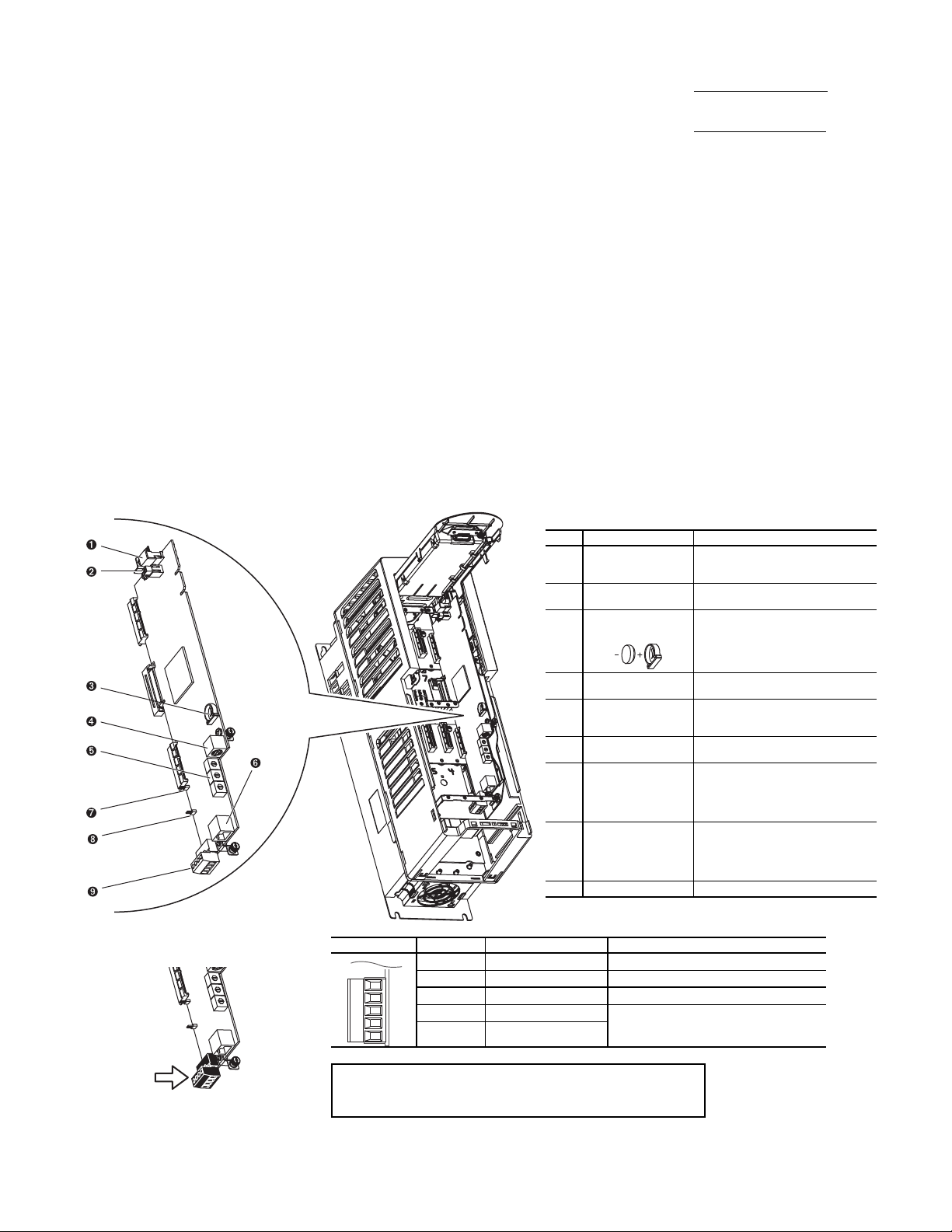
TB1 I/O TERMINAL DESIGNATIONS
FIXED I/O TERMINAL NAME DESCRIPTION
Di 0ac
Digital Input 120V AC Connections for AC power supply.
Di C
Digital Input Common Digital input common
Di 0dc
Digital Input 24V DC Connections for DC power supply.
+24V
+24 Volt Power Connections for drive supplied 24V power.
24VC
24 Volt Common
IMPORTANT: Wiring to pluggable terminal block connectors
should be supported by wire ties or other means to help prevent unintentional disconnection.
Di 0ac
Di C
Di 0dc
+24V
24VC
a19-1921
LEGEND
NO. NAME DESCRIPTION
1 HIM (Human
Interface Module)
Connector
DPI Port 1 (HIM Cradle) connection.
2
Fan Connector Power supply for internal cooling fan
(Frames 2 and 3).
3
Battery
Receptacle
User-installed CR1220 lithium coin
cell battery provides power to the
real-time clock (Optional, not
supplied).
4
DPI Port 2 Cable connection for handheld and
remote HIM options.
5
Embedded Ethernet/
IP Address Selectors
Rotary switches for setting lowest
octet of Ethernet address (forces
address to 192.168.1.xxx).
6
Embedded Ethernet/
IP Connector
Network cable connection.
7
Jumper J2 SAFETY
ENABLE
Safety enable jumper. Removed
when safety option is installed. For
additional information, refer to the
Check Internal Jumpers section on
page 9.
8
Jumper J1 HARDWARE ENABLE
Hardware enable jumper. Removed
when a hardware enable configuration is utilized. For additional information, refer to the Check Internal
Jumpers section on page 9.
9 TB1 I/O terminal block.
The commission procedure is as follows:
1. If the chiller has been stored outdoors, allow at least
24 hours room temperature stabilization prior to commissioning. Ensure any condensation that occurs as a result of
the ambient temperature is allowed to evaporate.
2. Enter parameters in the VFD_CONF screen.
3. Install surge suppression devices if required.
4. Review the power wiring and grounding to ensure that it
has been properly connected.
5. Visually examine the inside of the drive enclosure to:
a. Look for signs of corrosion or moisture residue.
b. Remove any dirt or debris.
c. Make sure all vents are clear.
6. Apply power to the drive and take thermal measurements
of the capacitor bank and power connections. Do this
again before start-up.
7. Measure and record the incoming line voltage. Line-toline voltages should be balanced within 3% as calculated
by Rockwell’s procedure below:
Measure voltages phase-to-phase and phase-to-ground.
Vmax = Maximum measured phase-to-phase voltage
(A to B, B to C, C to A)
Vmin = Minimum measured phase-to-phase voltage
Imbalance Calculation Formula
Va v g =
Imbalance % =
(VAB + VBC + VCA)
3
(Vmax – Vmin) x 100
Va v g
8. Take a final thermal measurement of the capacitor bank
and power after finalizing the installation to ensure all
connections are good.
9. If a ground fault occurs, then do the following:
a. Check for a ground in the motor or motor wiring.
b. Check for damage to wiring insulation and that wiring
is dry.
c. Verify the motor wiring is separated from ground and
there is no connection between phases.
d. Check for failed IGBTs.
10. If an overcurrent fault occurs, then do the following:
a. Check for excessive load and verify load limit settings
on the HMI.
b. Check motor and wiring insulation.
c. Check parameter settings on VFD_CONF screen in
the HMI (PIC3) or UM VFD Configuration for PIC 6.
Check Internal Jumpers
On the Main VFD Control board there are 2 jumpers labeled J1
HARDWARE ENABLE and J2 SAFETY ENABLE. J1 should
be removed and J2 should be in place. See Fig. 12.
Fig. 12 — PF755 Main Control Board
9
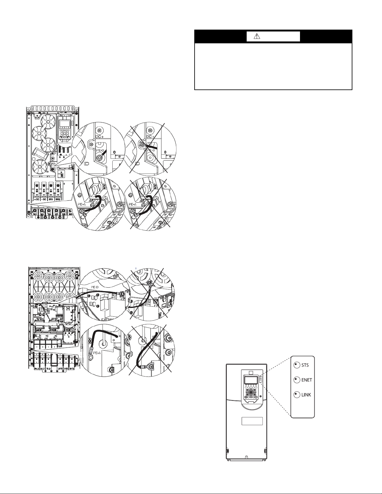
Two jumper wires connect a particular terminal to chassis ground.
CONNECTED
DISCONNECTED
COMMON MODE
MOV
A19-2325
CONNECTED
DISCONNECTED
COMMON MODE
MOV
A19-2326
2
8
5
79
1 3
46
Allen-Bradley
The MOV and AC EMI jumper should be connected to the PE-A
terminal. The COMMON MODE CAPACITORS to GROUND
jumper should be connected to a standoff rather than the PE-B
terminal.
Use the recommended tools as follows when connecting jumper
wires in Frame 6 and in Frame 7:
• Recommended torque (screws and nuts) = 1.36 N·m (120.0 lb·in.)
• Recommended hex socket = 7 mm
• Recommended screwdriver = T20 star type
See Fig. 13 and Fig. 14 for the correct positions of the jumpers.
Fig. 13 — Jumper Wire Locations — Frame 6
SERVICE
WARNING
DC bus capacitors retain hazardous voltages after input power
has been disconnected. After disconnecting input power, wait
five (5) minutes for the DC bus capacitors to discharge and
then check the voltage with a voltmeter to ensure the DC bus
capacitors are discharged before touching any internal components. Failure to observe this precaution could result in severe
bodily injury or loss of life.
Troubleshooting the Drive
The drive can display 2 kinds of error codes on the HMI called
Alert and Alarm codes. These codes signal a problem detected
during self-tuning or drive operation. Note the following differences between Carrier and Allen-Bradley terminology:
• A warning message on the HMI is an ALERT.
• The same warning viewed with Rockwell Drive Explorer
is a VFD ALARM.
• A failure resulting in a shutdown is seen as an ALARM on
the HMI and as a VFD FAULT when viewed with Drive
Explorer.
CONDITION CODES
CHILLER ALERT =VFD ALARM
CHILLER ALARM =VFD FAULT
See Tables 4-5 and Fig. 15.
CHILLER ALERT CODES
An alert condition is indicated by a message on the HMI screen.
The drive will continue to operate during the alert condition. Investigate the cause of the alert to ensure it does not lead to a fault
condition. The alert code will automatically be cleared from the
HMI when the condition causing the alert no longer exists. See the
19XRV or 23XRV Start-Up, Operation and Maintenance Instructions for ICVC alert codes or appropriate Controls Operation and
Troubleshooting manual for PIC6 controls.
CHILLER ALARM CODES
An alarm condition is also indicated by a message on the HMI
screen. If an alarm occurs, the drive coasts to stop. The STS (status) light on the drive will turn from green to red or yellow (see
Table 4). The detected fault message is maintained on the display
until it is cleared by pressing the RESET softkey. See the 19XRV
or 23XRV Start-Up, Operation and Maintenance Instructions for
ICVC alarm codes or appropriate Controls Operation and Troubleshooting manual for PIC6 controls.
TEST EQUIPMENT NEEDED TO TROUBLESHOOT
An isolated multimeter adequately rated for the DC bus voltage will
be needed to measure DC bus voltage and to make resistance checks.
Note that dedicated troubleshooting test points are not provided.
Fig. 14 — Jumper Wire Locations — Frame 7
Fig. 15 — Drive Status Indicator
10
Loading...