


19XR
19XR
Hermetic Centrifugal Liquid Chillers
50/60 Hz
With PIC II Controls and HFC-134a
Start-Up, Operation, and Maintenance Instructions
SAFETY CONSIDERATIONS
Centrifugal liquid chillers are designed to provide safe
and reliable service when operated within design specifications. When operating this equipment, use good judgment and safety precautions to avoid damage to equipment and property or injury to personnel.
Be sure you understand and follow the procedures and
safety precautions contained in the chiller instructions
as well as those listed in this guide.
DO NOT VENT refrigerant relief valves within a building. Outlet
from rupture disc or relief valve must be vented outdoors in accordance with the latest edition of ANSI/ASHRAE 15 (American
National Standards Institute/American Society of Heating, Refrigeration, and Air Conditioning Engineers). The accumulation of
refrigerant in an enclosed space can displace oxygen and cause
asphyxiation.
PROVIDE adequate ventilation in accordance with ANSI/ASHRAE
15, especially for enclosed and low overhead spaces. Inhalation of
high concentrations of vapor is harmful and may cause heart irregularities, unconsciousness, or death. Misuse can be fatal. Vapor
is heavier than air and reduces the amount of oxygen available for
breathing. Product causes eye and skin irritation. Decomposition
products are hazardous.
DO NOT USE OXYGEN to purge lines or to pressurize a chiller
for any purpose. Oxygen gas reacts violently with oil, grease, and
other common substances.
NEVER EXCEED specified test pressures, VERIFY the allowable
test pressure by checking the instruction literature and the design
pressures on the equipment nameplate.
DO NOT USE air for leak testing. Use only refrigerant or dry
nitrogen.
DO NOT VALVE OFF any safety device.
BE SURE that all pressure relief devices are properly installed and
functioning before operating any chiller.
RISK OF INJURY OR DEATH by electrocution. High voltage is
present on motor leads even though the motor is not running when
a solid-state or inside-delta mechanical starter is used. Open the
power supply disconnect before touching motor leads or terminals.
DO NOT WELD OR FLAMECUT any refrigerant line or vessel
until all refrigerant (liquid andvapor)hasbeenremovedfromchiller.
Traces of vapor should be displaced with dry air or nitrogen and
the work area should be well ventilated. Refrigerant in contact with
an open flame produces toxic gases.
DO NOT USE eyebolts or eyebolt holes to rig chiller sections or
the entire assembly.
DO NOT work on high-voltage equipment unless you are a qualified electrician.
DO NOTWORKON electrical components, including control panels, switches, starters, or oil heater until you are sure ALLPOWER
IS OFF and no residual voltage can leak from capacitors or solidstate components.
LOCK OPENANDTAGelectrical circuits during servicing.IF WORK
IS INTERRUPTED, confirm that all circuits are deenergized before resuming work.
AVOID SPILLING liquid refrigerant on skin or getting it into
the eyes. USE SAFETY GOGGLES. Wash any spills from the skin
with soap and water. If liquid refrigerant enters the eyes, IMMEDIATELY FLUSH EYES with water and consult a physician.
NEVER APPLY an open flame or live steam to a refrigerant
cylinder. Dangerous over pressure can result. When it is necessary
to heat refrigerant, use only warm (110 F [43 C]) water.
DO NOT REUSE disposable (nonreturnable) cylinders or attempt
to refill them. It is DANGEROUSAND ILLEGAL. When cylinder
is emptied, evacuate remaining gas pressure, loosen the collar and
unscrew and discard the valve stem. DO NOT INCINERATE.
CHECK THE REFRIGERANT TYPE before adding refrigerant to
the chiller.The introduction of the wrong refrigerant can cause damage or malfunction to this chiller.
Operation of this equipment with refrigerants other than those
cited herein should comply with ANSI/ASHRAE15 (latest edition). Contact Carrier for further information on use of this chiller
with other refrigerants.
DO NOTATTEMPTTO REMOVE fittings, covers,etc., while chiller
is under pressure or while chiller is running. Be sure pressure is at
0 psig (0 kPa) before breaking any refrigerant connection.
CAREFULLY INSPECT all relief devices, rupture discs, and other
relief devices AT LEAST ONCE A YEAR. If chiller operates in a
corrosive atmosphere, inspect the devices at more frequent
intervals.
DO NOT ATTEMPT TO REPAIR OR RECONDITION any relief
device when corrosion or build-up of foreign material (rust, dirt,
scale, etc.) is found within the valve body or mechanism. Replace
the device.
DO NOT install relief devices in series or backwards.
USE CARE when working near or in line with a compressed spring.
Sudden release of the spring can cause it and objects in its path to
act as projectiles.
DO NOT STEP on refrigerant lines. Broken lines can whip about
and release refrigerant, causing personal injury.
DO NOT climb over a chiller. Use platform, catwalk, or staging.
Follow safe practices when using ladders.
USE MECHANICAL EQUIPMENT (crane, hoist, etc.) to lift or
move inspection covers or other heavy components. Even if components are light, use mechanical equipment when there is a risk of
slipping or losing your balance.
BE AWARE that certain automatic start arrangements CAN
ENGAGE THE STARTER,TOWER FAN, OR PUMPS. Open the
disconnect ahead of the starter, tower fans, or pumps.
USE only repair or replacement parts that meet the code requirements of the original equipment.
DO NOTVENT OR DRAIN waterboxes containingindustrial brines,
liquid, gases, or semisolids without the permission of your process
control group.
DO NOT LOOSEN waterbox cover bolts until the waterbox has
been completely drained.
DOUBLE-CHECK that coupling nut wrenches, dial indicators, or
other items have been removed before rotating any shafts.
DO NOT LOOSEN a packing gland nut before checking that the
nut has a positive thread engagement.
PERIODICALLY INSPECT all valves, fittings, and piping for corrosion, rust, leaks, or damage.
PROVIDE A DRAIN connection in the vent line near each pressure relief device to prevent a build-up of condensate or rain water.
Manufacturer reserves the right to discontinue, or change at any time, specifications or designs without notice and without incurring obligations.
Book 2
Tab 5a
PC 211 Catalog No. 531-974 Printed in U.S.A. Form 19XR-3SS Pg 1 6-98 Replaces: New

CONTENTS
Page
SAFETY CONSIDERATIONS ................. 1
INTRODUCTION ............................ 4
ABBREVIATIONS AND EXPLANATIONS ...... 4
CHILLER FAMILIARIZATION ................ 5-7
Chiller Information Plate .................... 5
System Components ........................ 5
Cooler ..................................... 5
Condenser ................................. 5
Motor-Compressor .......................... 5
Control Panel .............................. 5
Factory-Mounted Starter (Optional) .......... 7
Storage Vessel (Optional) ................... 7
REFRIGERATION CYCLE .................... 7
MOTOR AND LUBRICATING OIL
COOLING CYCLE ........................ 7,8
LUBRICATION CYCLE ...................... 8
Summary .................................. 8
Details ..................................... 8
Oil Reclaim System ......................... 8
• PRIMARY OIL RECOVERY MODE
• SECONDARY OIL RECOVERY METHOD
STARTING EQUIPMENT .....................8-10
Unit-Mounted Solid-State Starter
(Optional) ................................ 9
Unit-Mounted Wye-Delta Starter
(Optional) ............................... 10
CONTROLS ...............................10-43
Definitions ................................ 10
• ANALOG SIGNAL
• DISCRETE SIGNAL
General ................................... 10
PIC II System Components ................. 10
• CHILLER VISUAL CONTROLLER (CVC)
• INTEGRATED STARTER MODULE (ISM)
• CHILLER CONTROL MODULE (CCM)
• OIL HEATER CONTACTOR (1C)
• OIL PUMP CONTACTOR (2C)
• HOT GAS BYPASS CONTACTOR RELAY (3C)
(Optional)
• CONTROL TRANSFORMERS (T1, T2)
CVC Operation and Menus ................. 14
• GENERAL
• ALARMS AND ALERTS
• CVC MENU ITEMS
• BASIC CVC OPERATIONS (Using the Softkeys)
• TO VIEW STATUS
• OVERRIDE OPERATIONS
• TIME SCHEDULE OPERATION
• TO VIEW AND CHANGE SET POINTS
• SERVICE OPERATION
PIC II System Functions ................... 32
• CAPACITY CONTROL
• ECW CONTROL OPTION
• CONTROL POINT DEADBAND
• DIFFUSER CONTROL
• PROPORTIONAL BANDS AND GAIN
• DEMAND LIMITING
• CHILLER TIMERS
• OCCUPANCY SCHEDULE
Safety Controls ............................ 33
Shunt Trip (Option) ........................ 35
Default Screen Freeze ..................... 35
Ramp Loading ............................. 35
Capacity Override ......................... 35
High Discharge Temperature Control ....... 35
Oil Sump Temperature Control ............. 35
Page
Oil Cooler ................................. 36
Remote Start/Stop Controls ................ 36
Spare Safety Inputs ........................ 36
Spare Safety Alarm Contacts .............. 36
Refrigerant Leak Detector ...................36
Condenser Pump Control .................. 36
Condenser Freeze Prevention .............. 37
Tower Fan Relay Low and High ............. 37
Auto. Restart After Power Failure ........... 37
Water/Brine Reset ......................... 37
• RESET TYPE 1
• RESET TYPE 2
• RESET TYPE 3
Demand Limit Control Option ................38
Surge Prevention Algorithm ................ 38
Surge Protection .......................... 39
Lead/Lag Control .......................... 39
• COMMON POINT SENSOR INSTALLATION
• CHILLER COMMUNICATION WIRING
• LEAD/LAG OPERATION
• FAULTED CHILLER OPERATION
• LOAD BALANCING
• AUTO. RESTART AFTER POWER FAILURE
Ice Build Control .......................... 41
• ICE BUILD INITIATION
• START-UP/RECYCLE OPERATION
• TEMPERATURE CONTROL DURING
ICE BUILD
• TERMINATION OF ICE BUILD
• RETURN TO NON-ICE BUILD OPERATIONS
Attach to Network Device Control .......... 42
• ATTACHING TO OTHER CCN MODULES
Service Operation ......................... 43
• TO ACCESS THE SERVICE SCREENS
• TO LOG OUT OF NETWORK DEVICE
• HOLIDAY SCHEDULING
START-UP/SHUTDOWN/RECYCLE
SEQUENCE .............................44,45
Local Start-Up ............................. 44
Shutdown Sequence ....................... 45
Automatic Soft Stop Amps Threshold ....... 45
Chilled Water Recycle Mode ................ 45
Safety Shutdown .......................... 45
BEFORE INITIAL START-UP ................46-58
Job Data Required ......................... 46
Equipment Required ....................... 46
Using the Optional Storage Tank
and Pumpout System .................... 46
Remove Shipping Packaging ............... 46
Open Oil Circuit Valves .................... 46
Tighten All Gasketed Joints and
Guide Vane Shaft Packing ................ 46
Check Chiller Tightness .................... 46
Refrigerant Tracer ......................... 46
Leak Test Chiller .......................... 48
Standing Vacuum Test ..................... 48
Chiller Dehydration ........................ 51
Inspect Water Piping ....................... 51
Check Optional Pumpout Compressor
Water Piping ............................ 51
Check Relief Valves ....................... 51
Inspect Wiring ............................. 51
Carrier Comfort Network Interface .......... 52
Check Starter ............................. 52
• MECHANICAL STARTER
• BENSHAW, INC. REDISTART MICRO
SOLID-STATE STARTER
Oil Charge ................................ 53
2

CONTENTS (cont)
Page
Power Up the Controls and
Check the Oil Heater ..................... 53
• SOFTWARE VERSION
Software Configuration .................... 53
Input the Design Set Points ................ 53
Input the Local Occupied Schedule
(OCCPC01S) ............................ 53
Input Service Configurations ............... 53
• PASSWORD
• INPUT TIME AND DATE
• CHANGE CVC CONFIGURATION
IF NECESSARY
• TO CHANGE THE PASSWORD
• TO CHANGE THE CVC DISPLAY FROM
ENGLISH TO METRIC UNITS
• MODIFY CONTROLLER IDENTIFICATION
IF NECESSARY
• INPUT EQUIPMENT SERVICE PARAMETERS
IF NECESSARY
• CONFIGURE DIFFUSER CONTROL IF
NECESSARY
• MODIFY EQUIPMENT CONFIGURATION
IF NECESSARY
Perform a Control Test ......................56
Check Optional Pumpout System
Controls and Compressor ................ 56
High Altitude Locations .................... 56
Charge Refrigerant Into Chiller ............. 56
• CHILLER EQUALIZATION WITHOUT A
PUMPOUT UNIT
• CHILLER EQUALIZATION WITH
PUMPOUT UNIT
• TRIMMING REFRIGERANT CHARGE
INITIAL START-UP .........................58,59
Preparation ............................... 58
Dry Run to Test Start-Up Sequence ......... 58
Check Motor Rotation ...................... 58
• IF THE MOTOR ROTATION IS CLOCKWISE
• IF THE MOTOR ROTATION IS NOT
CLOCKWISE
Check Oil Pressure and Compressor
Stop .................................... 59
To Prevent Accidental Start-Up ............. 59
Check Chiller Operating Condition .......... 59
Instruct the Customer Operator ............ 59
• COOLER-CONDENSER
• OPTIONAL PUMPOUT STORAGE TANK AND
PUMPOUT SYSTEM
• MOTOR COMPRESSOR ASSEMBLY
• MOTOR COMPRESSOR LUBRICATION
SYSTEM
• CONTROL SYSTEM
• AUXILIARY EQUIPMENT
• DESCRIBE CHILLER CYCLES
• REVIEW MAINTENANCE
• SAFETY DEVICES AND PROCEDURES
• CHECK OPERATOR KNOWLEDGE
• REVIEW THE START-UP, OPERATION, AND
MAINTENANCE MANUAL
OPERATING INSTRUCTIONS ...............59-61
Operator Duties ........................... 59
Prepare the Chiller for Start-Up ............. 59
To Start the Chiller ........................ 59
Check the Running System ................ 59
To Stop the Chiller ......................... 60
After Limited Shutdown .................... 60
Preparation for Extended Shutdown ........ 60
Page
After Extended Shutdown .................. 60
Cold Weather Operation ................... 60
Manual Guide Vane Operation .............. 60
Refrigeration Log .......................... 60
PUMPOUT AND REFRIGERANT TRANSFER
PROCEDURES ..........................62-64
Preparation ............................... 62
Operating the Optional Pumpout Unit ...... 62
• TO READ REFRIGERANT PRESSURES
Chillers with Storage Tanks ................ 63
• TRANSFER REFRIGERANT FROM
PUMPOUT STORAGE TANK TO CHILLER
• TRANSFER THE REFRIGERANT FROM
CHILLER TO PUMPOUT STORAGE TANK
Chillers with Isolation Valves ............... 64
• TRANSFER ALL REFRIGERANT TO
CHILLER CONDENSER VESSEL
• TRANSFER ALL REFRIGERANT TO
CHILLER COOLER VESSEL
• RETURN CHILLER TO NORMAL
OPERATING CONDITIONS
GENERAL MAINTENANCE .................65,66
Refrigerant Properties ..................... 65
Adding Refrigerant ........................ 65
Removing Refrigerant ...................... 65
Adjusting the Refrigerant Charge ........... 65
Refrigerant Leak Testing ................... 65
Leak Rate ................................. 65
Test After Service, Repair, or Major Leak .... 65
• REFRIGERANT TRACER
• TO PRESSURIZE WITH DRY NITROGEN
Repair the Leak, Retest, and Apply
Standing Vacuum Test ................... 65
Checking Guide Vane Linkage .............. 65
Trim Refrigerant Charge ................... 65
WEEKLY MAINTENANCE ................... 66
Check the Lubrication System .............. 66
SCHEDULED MAINTENANCE ..............66-69
Service Ontime ............................ 66
Inspect the Control Panel .................. 66
Check Safety and Operating Controls
Monthly ................................. 66
Changing Oil Filter ........................ 66
Oil Specification ........................... 67
Oil Changes ............................... 67
• TO CHANGE THE OIL
Refrigerant Filter .......................... 67
Oil Reclaim Filter .......................... 67
Inspect Refrigerant Float System ........... 67
Inspect Relief Valves and Piping ............ 67
Compressor Bearing and Gear
Maintenance ............................ 67
Inspect the Heat Exchanger Tubes
and Flow Devices ........................ 68
• COOLER AND FLOW DEVICES
• CONDENSER AND FLOW DEVICES
Water Leaks ............................... 68
Water Treatment ........................... 68
Inspect the Starting Equipment ............. 68
Check Pressure Transducers ............... 68
Optional Pumpout System Maintenance ..... 68
• OPTIONAL PUMPOUT COMPRESSOR OIL
CHARGE
• OPTIONAL PUMPOUT SAFETY CONTROL
SETTINGS
Ordering Replacement Chiller Parts ........ 69
3
CONTENTS (cont)
Page
TROUBLESHOOTING GUIDE ...............69-99
Overview .................................. 69
Checking the Display Messages ............ 69
Checking Temperature Sensors ............ 69
• RESISTANCE CHECK
• VOLTAGE DROP
• CHECK SENSOR ACCURACY
• DUAL TEMPERATURE SENSORS
Checking Pressure Transducers ............ 70
• COOLER AND CONDENSER PRESSURE
TRANSDUCER AND WATERSIDE FLOW DEVICE
CALIBRATION
• TRANSDUCER REPLACEMENT
Control Algorithms Checkout Procedure .... 70
Control Test ............................... 71
Control Modules ........................... 80
• RED LED (Labeled as STAT)
• GREEN LED (Labeled as COM)
Notes on Module Operation ................ 80
Page
Chiller Control Module (CCM) ................81
• INPUTS
• OUTPUTS
ISM Integrated Starter Module .............. 81
• INPUTS
• OUTPUTS
Replacing Defective Processor Modules .... 81
• INSTALLATION
Solid-State Starters ........................ 81
• TESTING SILICON CONTROL RECTIFIERS
IN BENSHAW, INC. SOLID-STATE STARTERS
• SCR REMOVAL/INSTALLATION
Physical Data ............................. 84
INDEX ..................................100,101
INITIAL START-UP CHECKLIST FOR
19XR HERMETIC CENTRIFUGAL
LIQUID CHILLER ..................CL-1 to CL-12
INTRODUCTION
Prior to initial start-up of the 19XR unit, those involved
in the start-up, operation, and maintenance should be thoroughly familiar with these instructions and other necessary
job data. This book is outlined to familiarize those involved
in the start-up, operation and maintenance of the unit with
the control system before performing start-up procedures. Procedures in this manual are arranged in the sequence required
for proper chiller start-up and operation.
This unit uses a microprocessor control system. Do not
short or jumper between terminations on circuit boards
or modules; control or board failure may result.
Be aware of electrostatic discharge (static electricity) when
handling or making contact with circuit boards or module connections. Always touch a chassis (grounded) part
to dissipate body electrostatic charge before working inside control center.
Use extreme care when handling tools near boards and
when connecting or disconnecting terminal plugs. Circuit boards can easily be damaged. Always hold boards
by the edges and avoid touching components and
connections.
This equipment uses, and can radiate, radio frequency
energy. If not installed and used in accordance with the
instruction manual, it may cause interference to radio
communications. It has been tested and found to comply with the limits for a Class A computing device pursuant to Subpart J of Part 15 of FCC Rules, which are
designed to provide reasonable protection against such
interference when operated in a commercial environment. Operation of this equipment in a residential area
is likely to cause interference, in which case the user, at
his own expense, will be required to take whatever measures may be required to correct the interference.
Always store and transport replacement or defective boards
in anti-static shipping bag.
ABBREVIATIONS AND EXPLANATIONS
Frequently used abbreviations in this manual include:
CCM — Chiller Control Module
CCN — Carrier Comfort Network
CVC — Chiller Visual Control
CCW — Counterclockwise
CW — Clockwise
ECDW — Entering Condenser Water
ECW — Entering Chilled Water
EMS — Energy Management System
HGBP — Hot Gas Bypass
I/O — Input/Output
ISM — Integrated Starter Module
LCD — Liquid Crystal Display
LCDW — Leaving Condenser Water
LCW — Leaving Chilled Water
LED — Light-Emitting Diode
OLTA — Overload Trip Amps
PIC II — Product Integrated Control II
RLA — Rated Load Amps
SCR — Silicon Controlled Rectifier
SI — International System of Units
TXV — Thermostatic Expansion Valve
W ordsprinted in all capital letters orin italics may be viewed
on the Chiller Visual Control (CVC) (e.g., LOCAL, CCN,
ALARM, etc.).
Words printed in both all capital letters and italics can also
be viewed on the CVC and are parameters (e.g., CONTROL
MODE, COMPRESSOR START RELAY, ICE BUILD
OPTION, etc.) with associated values (e.g., modes, tempera-
tures, percentages, pressures, on, off, etc.).
Words printed in all capital letters and in a box represent
softkeys on the CVC control panel (e.g., ENTER
, INCREASE , QUIT , etc.).
EXIT
Factory-installed additional components are referred to as
options in this manual; factory-supplied but field-installed
additional components are referred to as accessories.
The chiller software part number of the 19XR unit is located on the back of the CVC.
,
4
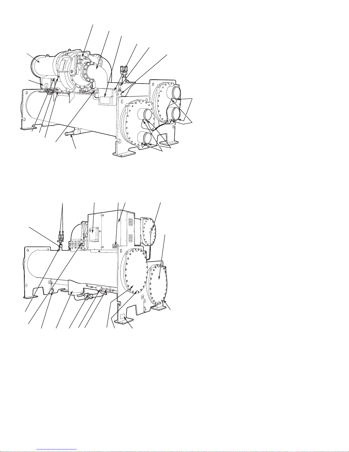
CHILLER FAMILIARIZATION
(Fig. 1 and 2)
Chiller Information Plate —
located on the right side of the chiller control panel.
The information plate is
System Components — The components include the
cooler and condenser heat exchangers in separate vessels,
motor-compressor, lubrication package, control panel, and
motor starter.All connections from pressure vessels have external threads to enable each component to be pressure tested
with a threaded pipe cap during factory assembly.
Cooler — This vessel (also known as the evaporator) is
located underneath the compressor. The cooler is maintained at lower temperature/pressure so evaporating refrigerant can remove heat from water flowing through its internal tubes.
Condenser — The condenser operates at a higher
temperature/pressure than the cooler and has water flowing
through its internal tubes in order to remove heat from the
refrigerant.
Motor-Compressor — This component maintains sys-
tem temperature and pressure differences and moves the heatcarrying refrigerant from the cooler to the condenser.
Control Panel — The control panel is the user interface
for controlling the chiller. It regulates the chiller’s capacity
as required to maintain proper leaving chilled water temperature. The control panel:
• registers cooler, condenser, and lubricating system
pressures
• shows chiller operating condition and alarm shutdown
conditions
• records the total chiller operating hours
• sequences chiller start, stop, and recycle under microprocessor control
• displays status of motor starter
• provides access to other CCN (Carrier Comfort Network)
devices
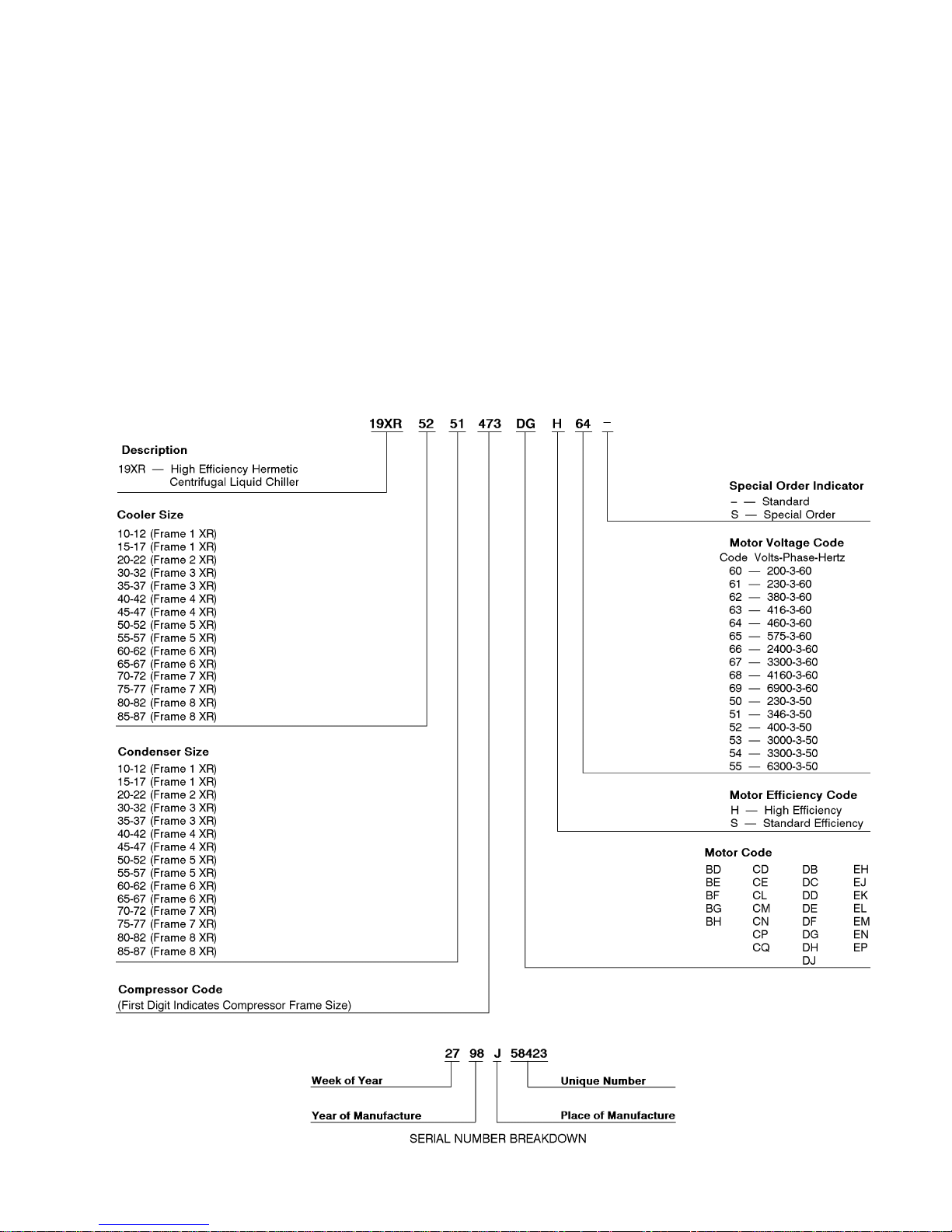
MODEL NUMBER NOMENCLATURE
Fig. 1 — 19XR Identification
5
1
2
3
4
5
17
16
15
14
13
12
11
6
7
8
9
10
1—Guide Vane Actuator
2—Suction Elbow
3—Chiller Visual Control (CVC)
4—Chiller Identification Nameplate
5—Cooler, Auto Reset Relief Valves
6—Cooler Pressure Transducer
7—Condenser In/Out Temperature
Thermistors
8—Condenser Waterflow Device
9—Cooler In/Out Temperature Thermistors
10 — Cooler Waterflow Device
11 — Refrigerant Charging Valve
12 — Typical Flange Connection
13 — Oil Drain Charging Valve
14 — Oil Level Sight Glasses
15 — Refrigerant Oil Cooler (Hidden)
16 — Auxiliary Power Panel
17 — Motor Housing
LEGEND
FRONT VIEW
18
34
33
32
31
30
28
29
19 20 21 22
27
26 25
24
18 — Condenser Auto. Reset Relief Valves
19 — Motor Circuit Breaker
20 — Solid-State Starter Control Display
21 — Unit-Mounted Starter (Optional),
Solid-State Starter Shown
23
24
22 — Motor Sight Glass
23 — Cooler Return-End Waterbox Cover
24 — ASME Nameplate (One Hidden)
25 — Typical Waterbox Drain Port
26 — Condenser Return-End Waterbox Cover
27 — Refrigerant Moisture/Flow Indicator
28 — Refrigerant Filter/Drier
29 — Liquid Line Isolation Valve (Optional)
30 — Linear Float Valve Chamber
31 — Vessel Take-Apart Connector
32 — Discharge Isolation Valve (Optional)
33 — Pumpout Valve
34 — Condenser Pressure Transducer
LEGEND
REAR VIEW
Fig.2—Typical 19XR Components
6
Factory-Mounted Starter (Optional)— The starter
allows for the proper start and disconnect of electrical energy for the compressor-motor, oil pump, oil heater,and control panel.
Storage Vessel (Optional) — There are 2 sizes of
storage vessels available. The vessels have double relief valves,
a magnetically-coupled dial-type refrigerant level gage, a
one-inch FPT drain valve, and a1⁄2-in. male flare vapor
connection for the pumpout unit.
NOTE: If a storage vessel is not used at the jobsite, factoryinstalled isolation valves on the chiller may be used to isolate the chiller charge in either the cooler or condenser.
An optional pumpout system is used to transfer refrigerant
from vessel to vessel.
REFRIGERATION CYCLE
The compressor continuously draws refrigerant vapor from
the cooler at a rate set by the amount of guide vane opening.
As the compressor suction reduces the pressure in the cooler,
the remaining refrigerant boils at a fairly low temperature
(typically 38 to 42 F [3 to 6 C]). The energy required for
boiling is obtained from the water flowing through the cooler
tubes. With heat energy removed, the water becomes cold
enough to use in an air conditioning circuit or for process
liquid cooling.
After taking heat from the water, the refrigerant vapor is
compressed. Compression adds still more heat energy, and
the refrigerant is quite warm (typically 98 to 102 F
[37 to 40 C]) when it is discharged from the compressor into
the condenser.
Relatively cool (typically 65 to 90 F [18 to 32 C]) water
flowing into the condenser tubes removes heat from the refrigerant and the vapor condenses to liquid.
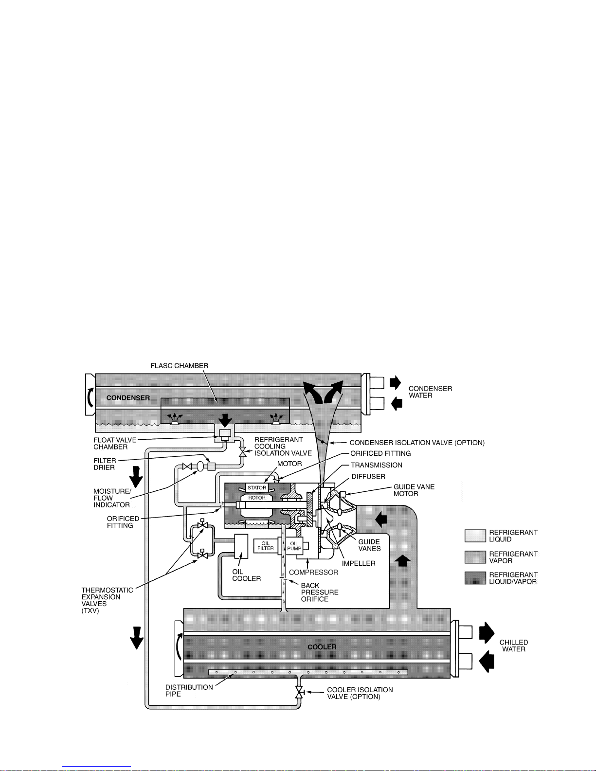
The liquid refrigerant passes through orifices into the FLASC
(Flash Subcooler) chamber (Fig. 3). Since the FLASC chamber is at a lower pressure, part of the liquid refrigerant flashes
to vapor, thereby cooling the remaining liquid. The FLASC
vapor is recondensed on the tubes which are cooled by entering condenser water. The liquid drains into a float chamber between the FLASC chamber and cooler. Here a float
valve forms a liquid seal to keep FLASC chamber vapor from
entering the cooler. When liquid refrigerant passes through
the valve, some of it flashes to vapor in the reduced pressure
on the cooler side. In flashing, it removes heat from the remaining liquid. The refrigerant is now at a temperature and
pressure at which the cycle began.
MOTOR AND LUBRICATING OIL
COOLING CYCLE
The motor and the lubricating oil are cooled by liquid refrigerant taken from the bottom of the condenser vessel
(Fig. 3). Refrigerant flow is maintained by the pressure differential that exists due to compressor operation. After the
refrigerant flows past an isolation valve, an in-line
filter, and a sight glass/moisture indicator, the flow is split
between the motor cooling and oil cooling systems.
Fig. 3 — Refrigerant Motor Cooling and Oil Cooling Cycles
7

Flow to the motor cooling system passes through an orifice and into the motor. Once past the orifice, the refrigerant
is directed over the motor by a spray nozzle. The refrigerant
collects in the bottom of the motor casing and is then drained
back into the cooler through the motor refrigerant drain line.
A back pressure valve or an orifice in this line maintains a
higher pressure in the motor shell than in the cooler/oil sump.
The motor is protected by a temperature sensor imbedded in
the stator windings. An increase in motor winding temperature past the motor override set point overrides the temperature capacity control to hold, and if the motor temperature
rises 10° F (5.5° C) above this set point, closes the inlet guide
vanes. If the temperature rises above the safety limit, the compressor shuts down.
Refrigerant that flows to the oil cooling system is regulated by thermostatic expansion valves (TXVs). The TXVs
regulate flow into the oil/refrigerant plate and frame-type heat
exchanger (the oil cooler in Fig. 3). The expansion valve
bulbs control oil temperature to the bearings. The refrigerant
leaving the oil cooler heat exchanger then returns to the chiller
cooler.
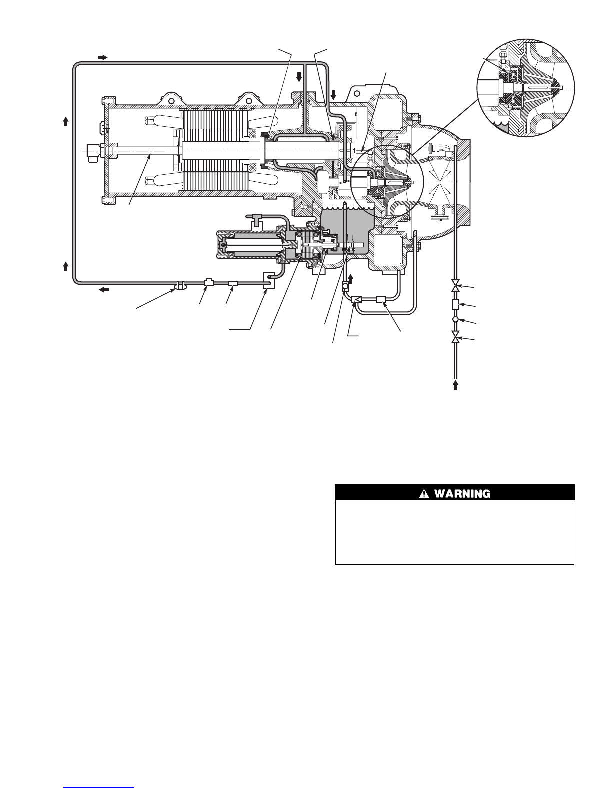
LUBRICATION CYCLE
Summary —
up a package located partially in the transmission casting of
the compressor-motor assembly. The oil is pumped into a
filter assembly to remove foreign particles and is then forced
into an oil cooler heat exchanger where the oil is cooled to
proper operational temperatures. After the oil cooler, part of
the flow is directed to the gears and the high speed shaft
bearings; the remaining flow is directed to the motor shaft
bearings. Oil drains into the transmission oil sump to complete the cycle (Fig. 4).
The oil pump, oil filter, and oil cooler make
Details— Oil is charged into the lubrication system through
a hand valve. Two sight glasses in the oil reservoir permit oil
level observation. Normal oil level is between the middle of
the upper sight glass and the top of the lower sight glass
when the compressor is shut down. The oil level should be
visible in at least one of the 2 sight glasses during operation.
Oil sump temperature is displayed on the CVC (Chiller
Visual Control) default screen. During compressor operation, the oil sump temperature ranges between 125 to 150 F
(52 to 66 C).
The oil pump suction is fed from the oil reservoir. An
oil pressure relief valve maintains 18 to 25 psid (124 to
172 kPad) differential pressure in the system at the pump
discharge.This differentialpressure can be read directly from
the CVC default screen. The oil pump discharges oil to the
oil filter assembly. This filter can be closed to permit
removal of the filter without draining the entire oil system
(see Maintenance sections, pages 65 to 69, for details). The
oil is then piped to the oil cooler heat exchanger. The oil
cooler uses refrigerant from the condenser as the coolant.
The refrigerant cools the oil to a temperature between 120
and 140 F (49 to 60 C).
As the oil leaves the oil cooler, it passes the oil pressure
transducer and the thermal bulb for the refrigerant expansion valve on the oil cooler. The oil is then divided. Part of
the oil flows to the thrust bearing, forward pinion bearing,
and gear spray. The rest of the oil lubricates the motor shaft
bearings and the rear pinion bearing. The oil temperature is
measured in the bearing housing as it leaves the thrust and
forward journal bearings. The oil then drains into the oil reservoir at the base of the compressor. The PIC II (Product
Integrated Control II) measures the temperature of the oil in
the sump and maintains the temperature during shutdown
(see Oil Sump Temperature Control section, page 35). This
temperature is read on the CVC default screen.
During the chiller start-up, the PIC IIenergizesthe oil pump
and provides 45 seconds of prelubrication to the bearings
after pressure is verified before starting the compressor.
During shutdown, the oil pump will run for 60 seconds to
post-lubricate after the compressor shuts down. The oil pump
can also be energized for testing purposes during a Control
Test.
Ramp loading can slow the rate of guide vane opening to
minimize oil foaming at start-up. If the guide vanes open
quickly, the sudden drop in suction pressure can cause any
refrigerant in the oil to flash. The resulting oil foam cannot be pumped efficiently; therefore, oil pressure falls off
and lubrication is poor. If oil pressure falls below 15 psid
(103 kPad) differential, the PIC II will shut down the
compressor.
If the controls are subject to a power failure that lasts more
than 3 hours, the oil pump will be energized periodically when
the power is restored. This helps to eliminate refrigerant that
has migrated to the oil sump during the power failure. The
controls energize the pump for 60 seconds every 30 minutes
until the chiller is started.
Oil Reclaim System — The oil reclaim system re-
turns oil lost from the compressor housing back to the oil
reservoir by recovering the oil from 2 areas on the chiller.
The guide vane housing is the primary area of recovery. Oil
is also recovered by skimming it from the operating refrigerant level in the cooler vessel.
PRIMARY OIL RECOVERY MODE — Oil is normally
recovered through the guide vane housing on the chiller.This
is possible because oil is normally entrained with refrigerant
in the chiller.As the compressor pulls the refrigerant up from
the cooler into the guide vane housing to be compressed, the
oil normally drops out at this point and falls to the bottom
of the guide vane housing where it accumulates. Using discharge gas pressure to power an eductor, the oil is drawn
from the housing and is discharged into the oil reservoir.
SECONDARY OIL RECOVERY METHOD — The secondary method of oil recovery is significant under light load
conditions, when the refrigerant going up to the compressor
suction does not have enough velocity in which to bring oil
along. Under these conditions, oil collects in a greater concentration at the top level of the refrigerant in the cooler.
This oil and refrigerant mixture is skimmed from the side of
the cooler and is then drawn up to the guide vane housing.
There is a filter in this line. Because the guide vane housing
pressure is much lower than the cooler pressure, the refrigerant boils off, leaving the oil behind to be collected by the
primary oil recovery method.
STARTING EQUIPMENT
The 19XR requires a motor starter to operate the centrifugal hermetic compressor motor, the oil pump, and various
auxiliary equipment. The starter is the main field wiring interface for the contractor.
See Carrier Specification Z-415 for specific starter requirements. All starters must meet these specifications in
order to properly start and satisfy mechanical safety requirements. Starters may be supplied as separate, free-standing
units or may be mounted directly on the chiller (unit mounted)
for low-voltage units only.
Three separate circuit breakers are inside the starter. Circuit breaker CB1 is the compressor motor circuit breaker.
The disconnect switch on the starter front cover is connected
to this breaker. Circuit breaker CB1 supplies power to the
compressor motor.
The main circuit breaker (CB1) on the front of the starter
disconnects the main motor current only. Power is still
energized for the other circuits. Two more circuit breakers inside the starter must be turned off to disconnect
power to the oil pump, PIC II controls, and oil heater.
8
MOTOR
COOLING LINE
TXV BULB PRESSURE
TRANSDUCER
REAR MOTOR
BEARING
ISOLATION
VALVE
OIL
COOLER
OIL PUMP
MOTOR
OIL
PUMP
OIL
HEATER
SIGHT GLASS
FWD MOTOR
BEARING
LABYRINTH
GAS LINE
FILTEREDUCTOR
OIL SUPPLY TO
FORWARD HIGH
SPEED BEARING
ISOLATION
VALVE
FILTER
SIGHT
GLASS
ISOLATION
VALVE
Fig. 4 — Lubrication System
Circuit breaker CB2 supplies power to the control panel,
oil heater, and portions of the starter controls.
Circuit breaker CB3 supplies power to the oil pump. Both
CB2 and CB3 are wired in parallel with CB1 so that power
is supplied to them if the CB1 disconnect is open.
All starters must include a Carrier control module called
the Integrated Starter Module (ISM), excluding the
Benshaw solid-state starters. This module controls and monitors all aspects of the starter. See the Controls section on
page 10 for additional ISM information. All starter replacement parts are supplied by the starter manufacturer excluding the ISM (contact Carrier’s Replacement Component
Division [RCD]).
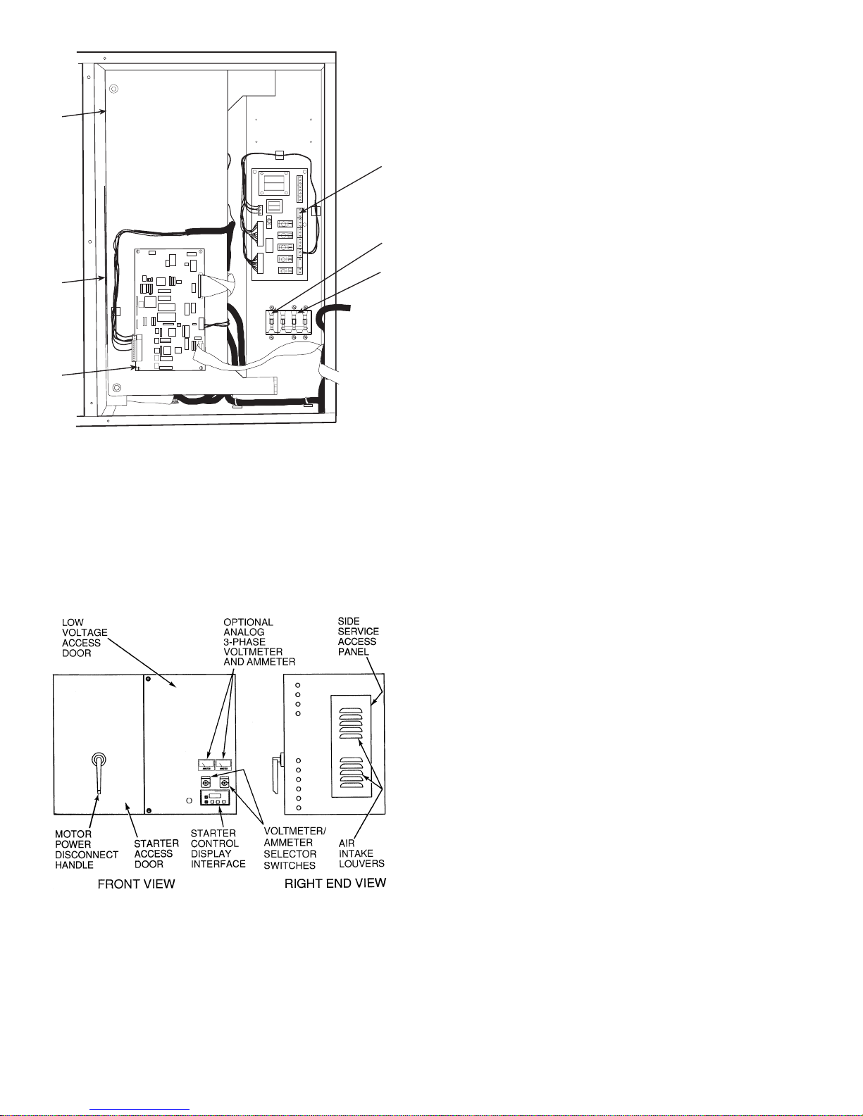
Unit-Mounted Solid-State Starter (Optional)
— The 19XR chiller may be equipped with a solid-state,
reduced-voltage starter (Fig. 5 and 6). This starter’s primary
function is to provide on-off control of the compressor motor. This type of starter reduces the peak starting torque,
reduces the motor inrush current, and decreases mechanical
shock. This capability is summed up by the phrase ‘‘soft starting.’’ The solid-state starter is available as a 19XR option
(factory supplied and installed). The solid-state starters manufacturer name is located inside the starter access door.
A solid-state, reduced-voltage starter operates by reducing the starting voltage. The starting torque of a motor at full
voltage is typically 125% to 175% of the running torque.
When the voltage and the current are reduced at start-up, the
starting torque is reduced as well. The object is to reduce the
starting voltage to just the voltage necessary to develop the
torque required to get the motor moving. The voltage is reduced by silicon controlled rectifiers (SCRs). The voltage
and current are then ramped up in a desired period of time.
Once full voltage is reached, a bypass contactor is energized
to bypass the SCRs.
When voltage is supplied to the solid-state circuitry, the
heat sinks in the starter as well as the wires leading to
the motor and the motor terminal are at line voltage.
Do not touch the heat sinks, power wiring, or motor
terminals while voltage is present or serious injury will
result.
There is a display on the front of the Benshaw,Inc., solidstate starters that is useful for troubleshooting and starter checkout. The display indicates:
• voltage to the SCRs
• SCR control voltage
• power indication
• proper phasing for rotation
• start circuit energized
• over-temperature
• ground fault
• current unbalance
• run state
• software configuration
The starter is further explained in the Check Starter and
Troubleshooting Guide sections, pages 52 and 66.
9
Unit-Mounted Wye-Delta Starter (Optional)
The 19XR chiller may be equipped with a wye-delta starter
—
mounted on the unit. This starter is intended for use with
low-voltage motors (under 600 v). It reduces the starting
6
1
current inrush by connecting each phase of the motor
windings into a wye configuration. This occurs during the
starting period when the motor is accelerating up to speed.
Once the motor is up to speed, the starter automatically connects the phase windings into a delta configuration. Starter
control, monitoring, and motor protection is provided by
Carrier’s Integrated Starter Module (ISM).
5
4
LEGEND
1—Ready-Start Micro Input/Output Card
2—Circuit Breaker 2 (CB2):
Machine Control and Heater Power
3—Circuit Breaker 3 (CB3): Oil Pump Power
4—Ready-Start Micro Central Processing Unit Card (CPU)
5—Restart Micro Power Card (hidden, not depicted)
6—Restart Micro Bypass Card (hidden, not depicted)
Fig. 5 — Solid-State Starter Box,
Internal View
2
CONTROLS
Definitions
3
ANALOG SIGNAL — An analog signal varies in proportion to the monitored source. It quantifies values between
operating limits. (Example: A temperature sensor is an analog device because its resistance changes in proportion to
the temperature, generating many values.)
DISCRETE SIGNAL — A discrete signal is a 2-position representation of the value of a monitored source. (Example: A
switch produces a discrete signal indicating whether a value
is above or below a set point or boundary by generating an
on/off, high/low, or open/closed signal.)
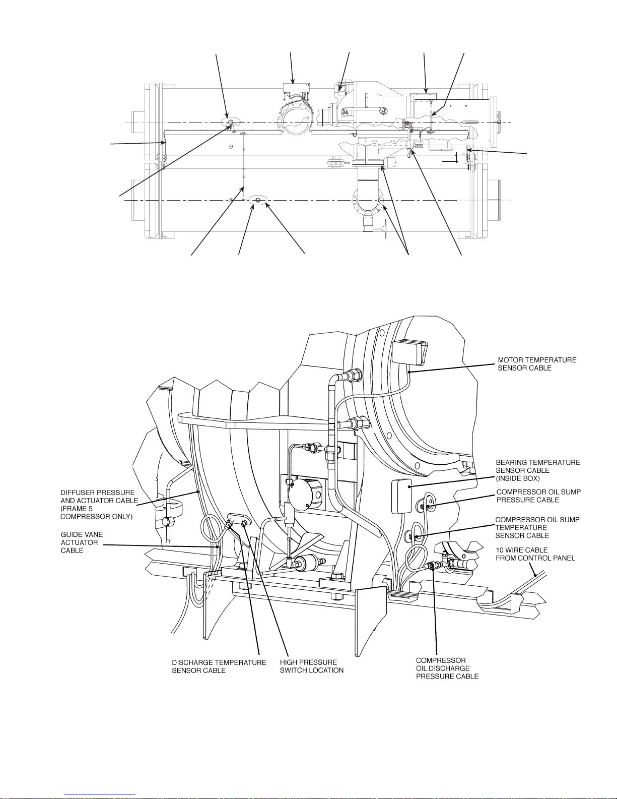
General — The 19XR hermetic centrifugal liquid chiller
contains a microprocessor-based control center that monitors and controls all operations of the chiller (see Fig. 7).
The microprocessor control system matches the cooling
capacity of the chiller to the cooling load while providing
state-of-the-art chiller protection. The system controls cooling load within the set point plus the deadband by sensing
the leaving chilled water or brine temperature and regulating the inlet guide vane via a mechanically-linked actuator
motor. The guide vane is a variable flow pre-whirl assembly that controls the refrigeration effect in the cooler by
regulating the amount of refrigerant vapor flow into the compressor.An increase in guide vane opening increases capacity.Adecrease in guide vane opening decreases capacity.The
microprocessor-based control center protects the chiller by
monitoring the digital and analog inputs and executing
capacity overrides or safety shutdowns, if required.
Fig.6—Typical Starter External View
(Solid-State Starter Shown)
PIC II System Components — The chiller control
system is called the PIC II (Product Integrated Control II).
See Table 1. The PIC II controls the operation of the chiller
by monitoring all operating conditions. The PIC II can diagnose a problem and let the operator know what the problem is and what to check. It promptly positions the guide
vanes to maintain leaving chilled water temperature. It can
interface with auxiliary equipment such as pumps and cooling tower fans to turn them on when required. It continually
checks all safeties to prevent any unsafe operating condition. It also regulates the oil heater while the compressor is
off and regulates the hot gas bypass valve, if installed. The
PIC II controls provide critical protection for the compressor motor and controls the motor starter.
10
WATER
SENSOR
CABLES
COOLER
PRESSURE
CONNECTION
COOLER SCHRADER
FITTING (HIDDEN)
CONTROL
PANEL
GUIDE VANE
ACTUATOR CABLE
POWER
PANEL
COMMUNICATION
CABLE
WATER
SENSOR
CABLES
CONDENSER
PRESSURE
CABLE
CONDENSER
SCHRADER
FITTING (HIDDEN)
CONDENSER
PRESSURE
CONNECTION
TRANSDUCER
TOP VIEW
COMPRESSOR
DISCHARGE
ELBOW JOINTS
MOTOR WINDING
TEMPERATURE
CABLE
VIEWA—A(COMPRESSOR DETAIL)
Fig. 7 — 19XR Controls and Sensor Locations
11
The PIC II can interface with the Carrier Comfort Network (CCN) if desired. It can communicate with other
PIC I or PIC II equipped chillers and other CCN devices.
The PIC II consists of 3 modules housed inside 3 major
components. The component names and corresponding control voltages are listed below (also see Table 1):
• control panel
— all extra low-voltage wiring (24 v or less)
• power panel
— 230 or 115 v control voltage (per job requirement)
— up to 600 v for oil pump power
• starter cabinet
— chiller power wiring (per job requirement)
Table 1 — Major PIC Components and
Panel Locations*
PIC II COMPONENT PANEL LOCATION
Chiller Visual Controller (CVC) and Display Control Panel
Integrated Starter Module (ISM) Starter Cabinet
Chiller Control Module (CCM) Control Panel
Oil Heater Contactor (1C) Power Panel
Oil Pump Contactor (2C) Power Panel
Hot Gas Bypass Relay (3C) (Optional) Power Panel
Control Transformers (T1, T2) Power Panel
Temperature Sensors See Fig. 7.
Pressure Transducers See Fig. 7.
*See Fig. 5 and Fig. 7-11.
CHILLER VISUAL CONTROLLER (CVC) — The CVC is
the ‘‘brain’’ of the PIC II. This module contains all the operating software needed to control the chiller. The CVC is
mounted to the control panel (Fig. 10) and is the input center
for all local chiller set points, schedules, configurable
functions, and options. The CVC has a stop button, an alarm
light, four buttons for logic inputs, and a backlight display.
The backlight will automatically turn off after 15 minutes of
non-use. The functions of the four buttons or ‘‘softkeys’’ are
menu driven and are shown on the display directly above
the softkeys.
The viewing angle of the CVC can be adjusted for optimum viewing. Remove the 2 bolts connecting the control
panel to the brackets attached to the cooler. Place them in
one of the holes to pivot the control panel forward to backward to change the viewing angle. See Fig. 10. To change
the contrast of the display, access the adjustment on the back
of the CVC. See Fig. 10.
INTEGRATED STARTER MODULE (ISM) — This module is located in the starter cabinet. This module initiates commands from the CVC for starter functions such as starting
and stopping the compressor, condenser, chilled water pumps,
tower fan, spare alarm contacts, and the shunt trip. The ISM
monitors starter inputs such as line voltage, motor current,
ground fault, remote start contact, spare safety, condenser
high pressure, oil pump interlock, starter 1M, and run contacts. The ISM contains logic capable of safety shutdown. It
shuts down the chiller if communications with the CVC
are lost.
CHILLER CONTROL MODULE (CCM) — This module
is located in the control panel. The CCM provides the input
and outputs necessary to control the chiller. This module monitors refrigerant pressure, entering and leaving water temperatures, and outputs control for the guide vane actuator,
oil heaters, and oil pump. The CCM is the connection point
for optional demand limit, chilled water reset, remote temperature reset, and refrigerant leak sensor.
OIL HEATER CONTACTOR (1C) — This contactor is located in the power panel (Fig. 11) and operates the heater at
either 115 or 230 v. It is controlled by the PIC II to maintain
oil temperature during chiller shutdown.
OIL PUMP CONTACTOR (2C) — This contactor is located
in the power panel. It operates all 200 to 575-v oil pumps.
The PIC II energizes the contactor to turn on the oil pump
as necessary.
HOT GAS BYPASS CONTACTOR RELAY (3C) (Optional) — This relay, located in the power panel, controls the
opening of the hot gas bypass valve. The PIC II energizes
the relay during low load, high lift conditions.
CONTROL TRANSFORMERS (T1, T2) — These transformers convert incoming control voltage to 24 vac power
for the 3 power panel contactor relays, CCM, and CVC.
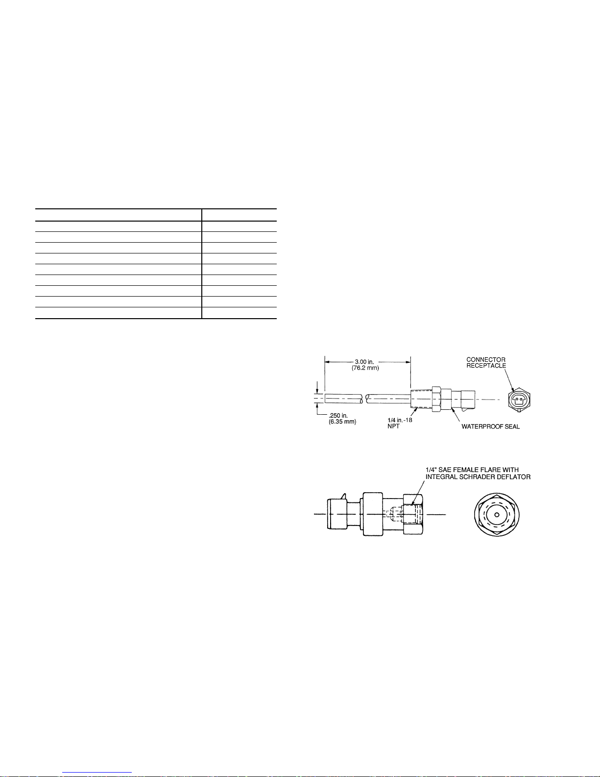
Fig. 8 — Control Sensors (Temperature)
Fig. 9 — Control Sensors
(Pressure Transducers, Typical)
12
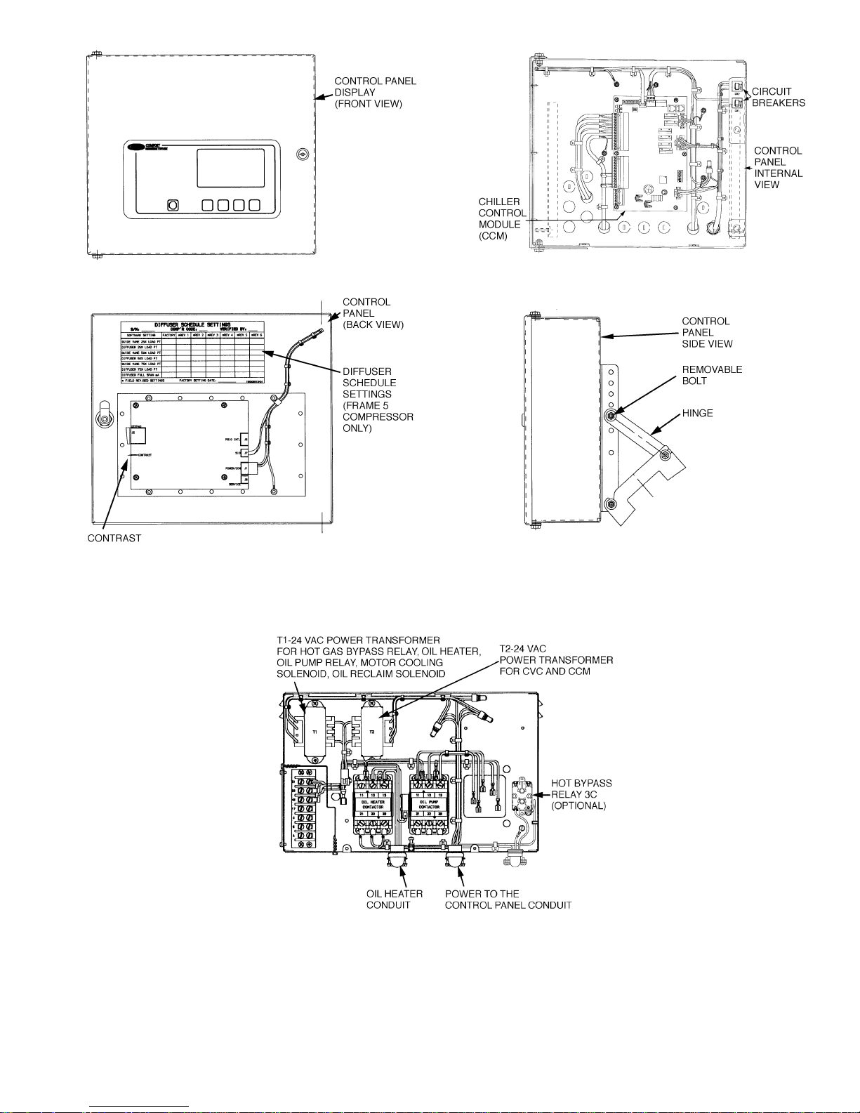
Fig. 10 — Control Panel
Fig. 11 — Power Panel
13
CVC Operation and Menus (Fig. 12-18)
GENERAL
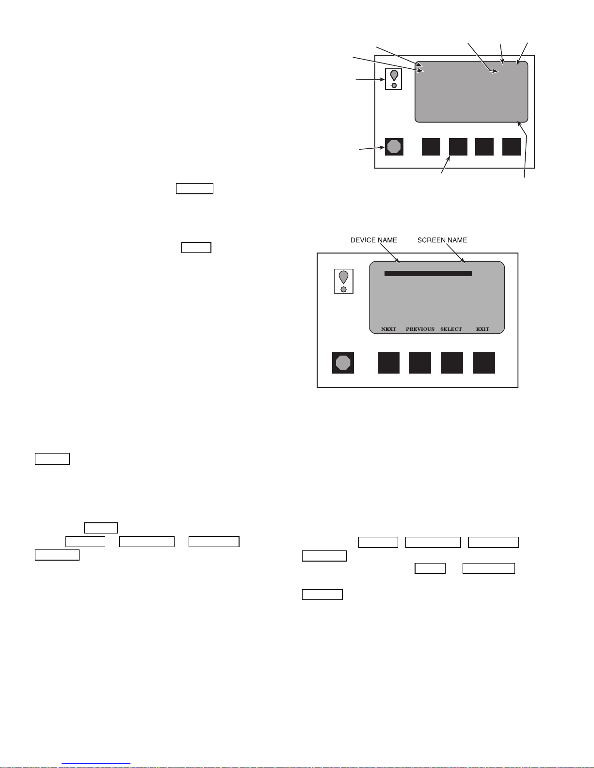
• The CVC display automatically reverts to the default screen
after 15 minutes if no softkey activity takes place and if
the chiller is not in the pumpdown mode (Fig. 12).
• If a screen other than the default screen is displayed on the
CVC, the name of that screen is in the upper right corner
(Fig. 13).
• The CVC may be set to display either English or SI units.
Use the CVC configuration screen (accessed from the Service menu) to change the units. See the Service Operation
section, page 43.
• Local Operation — The PIC II can be placed in local
operating mode by pressing the LOCAL
PIC II then accepts commands from the CVC only and
uses the Local Time Schedule to determine chiller start
and stop times.
• CCN Operation — The PIC II can be placed in the CCN
operating mode by pressing the CCN
PIC II then accepts modifications from any CCN interface
or module (with the proper authority), as well as from the
CVC. The PIC II uses the CCN time schedule to determine start and stop times.
ALARMSANDALERTS — An alarm shuts down the compressor. An alert does not shut down the compressor, but it
notifies the operator that an unusual condition has occurred.
An alarm (*) or alert (!) is indicated on the STATUS screens
on the far right field of the CVC display screen.
Alarms are indicated when the control center alarm light
(!) flashes. The primary alarm message is displayed on the
default screen. An additional, secondary message and
troubleshooting information are sent to the ALARM HISTORY table.
When an alarm is detected, the CVC default screen will
freeze (stop updating) at the time of alarm. The freeze enables the operator to view the chiller conditions at the time
of alarm. The STATUS tables will show the updated information. Once all alarms have been cleared (by pressing the
RESET
softkey), the default CVC screen will return to nor-
mal operation.
CVC MENU ITEMS — To perform any of the operations
described below, the PIC II must be powered up and have
successfully completed its self test. The self test takes place
automatically, after power-up.
Press the MENU
tures: STATUS
SERVICE
.
softkey to view the list of menu struc-
, SCHEDULE , SETPOINT , and
• The STATUS menu allows viewing and limited calibra-
tion or modification of control points and sensors, relays
and contacts, and the options board.
• The SCHEDULE menu allows viewing and modification
of the local and CCN time schedules and Ice Build time
schedules.
• The SETPOINT menu allows set point adjustments, such
as the entering chilled water and leaving chilled water set
points.
softkey. The
softkey. The
PRIMARY STATUS
MESSAGE
SECONDARY
STA TUS
MESSAGE
ALARM LIGHT
(ILLUMINATED
WHEN POWER ON)
BLINKS CONTINUOUSLY
•
ON FOR AN ALARM
BLINKS ONCE TO
•
CONFIRM A STOP
STOP BUTTON
HOLD FOR ONE
•
SECOND TO STOP
COMPRESSOR
ONTIME
RUNNING TEMP CONTROL
LEAVING CHILLED WATER
CHW IN CHW OUT EVAP REF
55.1 44.1 40.7
CDW IN CDW OUT COND REF
85.0 95.0 98.1
OIL PRESS OIL TEMP AMPS %
21.8 132.9 93
CCN LOCAL RESET MENU
SOFT KEYS
EACH KEY'S FUNCTION IS
DEFINED BY THE MENU DESCRIPTION
ON MENU LINE ABOVE
DATE TIME
01-01-95 11:48
28.8 HOURS
MENU
LINE
Fig. 12 — CVC Default Screen
19XR_II
ALARM HISTORY
CONTROL TEST
CONTROL ALGORITHM STATUS
EQUIPMENT CONFIGURATION
ISM (STARTER) CONFIGURATION DATA
EQUIPMENT SERVICE
TIME AND DATE
ATTACH TO NETWORK DEVICE
LOG OUT OF DEVICE
CVC CONFIGURATION
SERVICE
Fig. 13 — CVC Service Screen
• The SERVICE menu can be used to view or modify
information on the Alarm History, Control Test, Control
Algorithm Status, Equipment Configuration, ISM Starter
Configuration data, Equipment Service, Time and Date, Attach to Network Device, Log Out of Network Device, and
CVC Configuration screens.
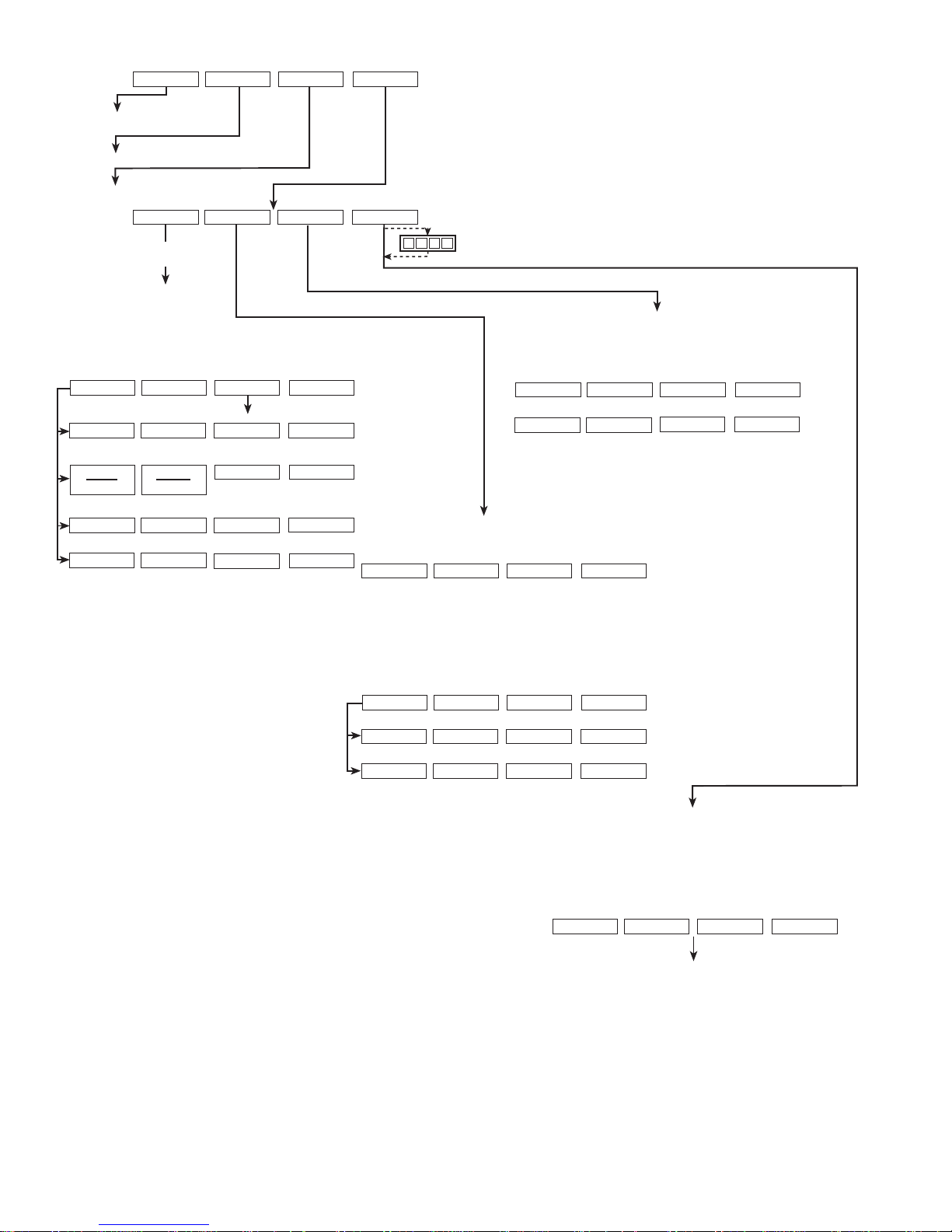
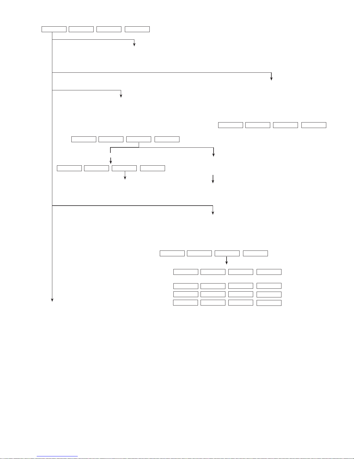
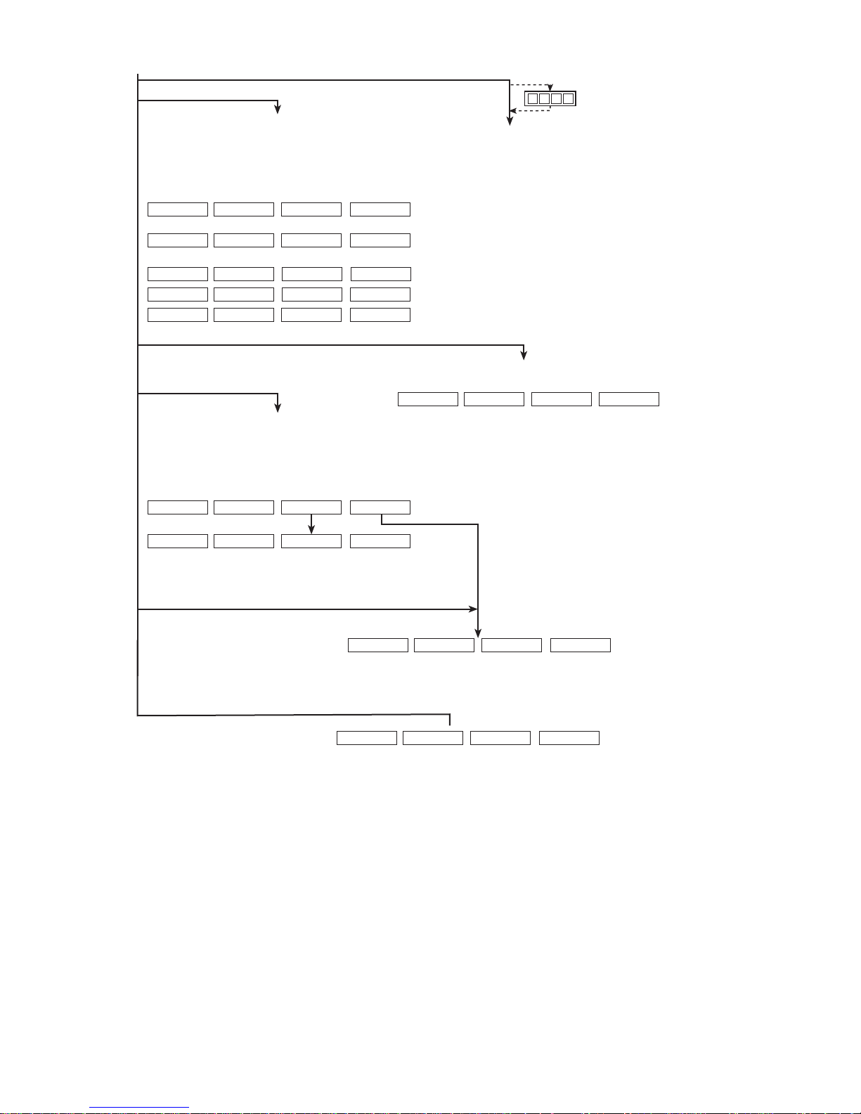
For more information on the menu structures, refer to
Fig. 15.
Press the softkey that corresponds to the menu structure
to be viewed : STATUS
SERVICE
. To view or change parameters within any of
these menu structures, use the NEXT
, SCHEDULE , SETPOINT ,or
and PREVIOUS soft-
keys to scroll down to the desired item or table. Use the
SELECT
softkey to select that item. The softkey choices
that then appear depend on the selected table or menu. The
softkey choices and their functions are described below.
BASIC CVC OPERA TIONS(Using the Softkeys) — Toperform any of the operations described below, the PIC II must
be powered up and have successfully completed its self test.
14
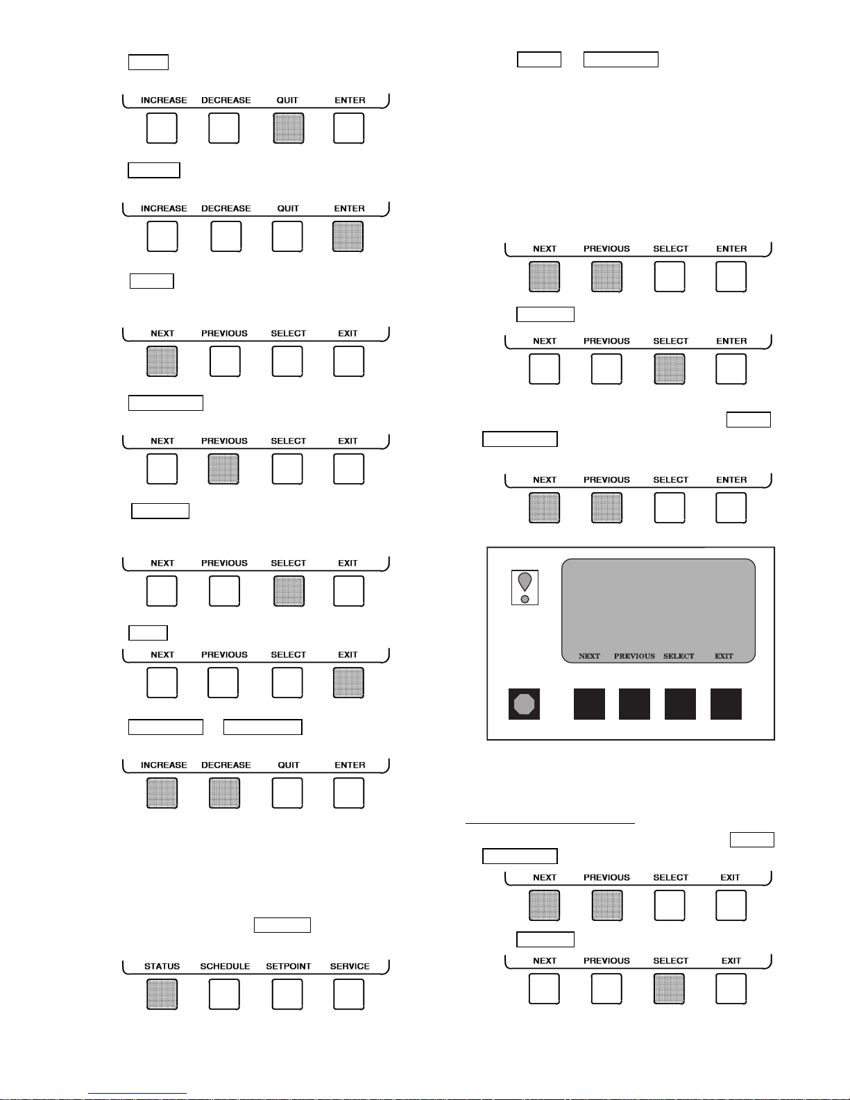
• Press QUIT to leave the selected decision or field without saving any changes.
• Press ENTER to leave the selected decision or field and
save changes.
• Press NEXT to scroll the cursor bar down in order to
highlight a point or to view more points below the current
screen.
• Press PREVIOUS to scroll the cursor bar up in order to
highlight a point or to view points above the current screen.
2. Press NEXT or PREVIOUS to highlight the desired
status table. The list of tables is:
• MAINSTAT — Overall chiller status
• STAR TUP— Status required to perform startup of chiller
• COMPRESS — Status of sensors related to the
compressor
• HEAT_EX — Status of sensors related to the heat
exchangers
• POWER — Status of motor input power
• ISM_STAT — Status of motor starter
• CVC_PSWD — Service menu password forcing ac-
cess screen
3. Press SELECT to view the desired point status table.
4. On the point status table, press NEXT or
PREVIOUS
until the desired point is displayed on the
screen.
• Press SELECT to view the next screen level (highlighted with the cursor bar), or to override (if allowable)
the highlighted point value.
• Press EXIT to return to the previous screen level.
• Press INCREASE or DECREASE to change the highlighted point value.
TO VIEW STATUS (Fig. 14) — The status table shows the
actual value of overall chiller status such as CONTROLMODE,
RUN STATUS, AUTO CHILLED WATER,RESET, and REMOTE RESET SENSOR.
1. On the menu screen, press STATUS
to view the list of
point status tables.
19XR_II MAINSTAT
Control Mode
Run Status
Start Inhibit Timer
Occupied?
System Alert/Alarm
Chiller Start/Stop
Remote Start Contact
Temperature Reset
Control Point
Chilled Water Temp
Active Demand Limit
Average Line Current
POINT STATUS
OFF
Ready
0.0 Min
NO
NORMAL
STOP
Open
0.0 F
44.0 F
44.6 F
100%
0.0%
Fig. 14 — Example of Status Screen
OVERRIDE OPERATIONS
To Override a Value or Status
1. From any point status screen, press NEXT or
PREVIOUS
to highlight the desired value.
2. Press SELECT to select the highlighted value. Then:
15
CCN
Start Chiller In CCN Control
Start Chiller in Local Control
DEFAULT SCREEN
LOCAL RESET
MENU
(SOFTKEYS)
Clear Alarms
STATUS
List the
Status Tables
• MAINSTAT
• STARTUP
• COMPRESS
• HEAT_EX
• POWER
• ISM_STAT
• CVC_PSWD
Select a Status Table
NEXT
Select a Modification Point
NEXT
Modify a Discrete Point
STOP
ON
Modify an Analog Point
INCREASE
Modify Control Options
ENABLE
PREVIOUS
PREVIOUS
START
OFF
DECREASE
DISABLE
Access Main Menu
SCHEDULE SETPOINT
SELECT
SELECT
RELEASE
RELEASE
RELEASE
EXIT
EXIT
ENTER
ENTER
ENTER
SERVICE
(ENTER A 4-DIGIT PASSWORD)
1
1
1
1
Display The Setpoint Table
List the Schedules
• LCW Setpoint
• ECW Setpoint
• Ice Build Setpoint
Select the Setpoint
NEXT
Modify the Setpoint
INCREASE
• OCCPC01S – LOCAL TIME SCHEDULE
• OCCPC02S – ICE BUILD TIME SCHEDULE
• OCCPC03S – CCN TIME SCHEDULE
Select a Schedule
NEXT
Select a Time Period/Override
NEXT
Modify a Schedule Time
INCREASE DECREASE ENTER EXIT
Add/Eliminate a Day
ENABLE DISABLE
PREVIOUS
PREVIOUS
SELECT
1
2
3
4
5
6
7
8
Override
SELECT
ENTER EXIT
• Tower Fan High Setpoint
PREVIOUS
DECREASE
EXIT
EXIT
•
Base Demand Limit
SELECT
QUIT
(ANALOG VALUES)
(DISCRETE VALUES)
List the Service Tables
EXIT
ENTER
Fig. 15 — 19XR CVC Menu Structure
16
NEXT
ALARM HISTORY
CONTROL TEST
CONTROL ALGORITHM STA TUS
EQUIPMENT CONFIGURATION
ISM (STARTER) CONFIG DATA
EQUIPMENT SERVICE
TIME AND DATE
ATTACH TO NETWORK DEVICE
LOG OUT OF DEVICE
CVC CONFIGURATION
PREVIOUS
SEE FIGURE 16
SELECT
EXIT
SERVICE TABLE
NEXT
PREVIOUS
ALARM HISTORY
CONTROL TEST
CONTROL ALGORITHM STA TUS
List the Control Algorithm Status Tables
• CAPACITY (Capacity Control)
• OVERRIDE (Override Status)
• LL_MAINT (Lead Lag Status)
• ISM_HIST (ISM Alarm History)
• LOADSHED
• WSMDEFME (Water System Manager Control Status)
• OCCDEFCM (Time Schedule Status)
Select a Table
NEXT
SELECT
Display Alarm History
(The table holds up to 25 alarms and
alerts with the most recent alarm
at the top of the screen.)
PREVIOUS
EXIT
SELECT
EXIT
List the Control Tests
Select a Test
NEXT
• CCM Thermistors
• CCM Pressure Transducers
• Pumps
• Discrete Outputs
• Guide Vane Actuator
• Diffuser Actuator
• Pumpdown/Lockout
• Terminate Lockout
• Guide Vane Calibration
PREVIOUS
SELECT
EXIT
OCCDEFM (Time Schedule Status)
Data Select Table
NEXT
EQUIPMENT CONFIGURATION List the Equipment Configuration Tables
CONTINUED
ON NEXT PAGE
PREVIOUS
SELECT
OCCPC01S (Local Status)
OCCPC02S (CCN, ICE BUILD Status)
OCCPC03S (CCN Status)
EXIT
Select a Table
NEXT
Select a Parameter
Modify a Parameter
INCREASE
ENABLE
Fig. 16 — 19XR Service Menu Structure
• CAPACITY (Capacity Control Algorithm)
• OVERRIDE (Override Status)
• LL_MAINT (LEADLAG Status)
• WSMDEFM2 (Water System Manager Control Status)
Maintenance Table Data
• NET_OPT
• BRODEF
• OCCEFCS
• HOLIDAYS
• CONSUME
• RUNTIME
PREVIOUS
DISABLE
NO
SELECT
EXIT
SELECT
QUIT
QUIT
QUIT
PREVIOUS
NEXT
DECREASE
YES
EXIT
ENTER
ENTER
ENTER
(ANALOG VALUES)
(DISCRETE VALUES)
(DISCRETE VALUES)
17
SERVICE MENU CONTINUED
FROM PREVIOUS PAGE
EQUIPMENT SERVICE
Select a Service Table
NEXT
Select a Service Table Parameter
NEXT
Modify a Service Table Parameter
INCREASE
ENABLE
NO
TIME AND DATE
ATTACH TO NETWORK DEVICE
Select a Device
NEXT
Modify Device Address
INCREASE
• Use to attach CVC to another CCN network or device
• Attach to "LOCAL" to enter this machine
• To upload new tables
PREVIOUS
PREVIOUS
DECREASE
DISABLE
PREVIOUS
DECREASE
ISM (STARTER CONFIG DATA)
Service Tables:
• OPTIONS
• SETUP1
• SETUP2
• LEADLAG
• RAMP_DEM
• TEMP_CTL
SELECT
SELECT
QUIT
QUIT
YES
List Network Devices
• Local
• Device 1
• Device 2
• Device 3
• Device 4
• Device 5
QUIT
• Device 6
• Device 7
• Device 8
• Device 9
SELECT
ENTER
EXIT
EXIT
ENTER
ENTER
ENTER
ATTACH
EXIT
(ANALOG VALUES)
(DISCRETE VALUES)
(DISCRETE VALUES)
Display Time and Date Table:
• To Modify — Current Time — Day of Week
INCREASE
DECREASE
(ENTER A 4-DIGIT PASSWORD)
4
4
4
4
Service Tables:
• ISM (STARTER) CONFIG PASSWORD
• ISM_CONFIG
— Current Date — Holiday Today
ENTER
EXIT
LOG OUT OF DEVICE
CVC CONFIGURATION
LEGEND
CCN — Carrier Comfort Network
CVC — Chiller Visual Control
ISM — Integrated Starter Module
PIC II — Product Integrated Control II
Default Screen
CCN
CVC Configuration Table
INCREASE
• To Modify — CVC CCN Address
— English or S.I. Metric Units
— Password
LOCAL
DECREASE
RESET
ENTER
• To View — CVC Software Version
(last 2 digits of part number
Fig. 16 — 19XR Service Menu Structure (cont)
MENU
EXIT
indicate software version)
18
For Discrete Points — Press START or STOP to select the desired state.
For Analog Points — Press INCREASE or
DECREASE
to select the desired value.
3. Press ENTER to register the new value.
NOTE: When overriding or changing metric values, it is necessary to hold down the softkey for a few seconds in order
to see a value change, especially on kilopascal values.
2. Press NEXT or PREVIOUS to highlight the desired schedule.
OCCPC01S — LOCAL Time Schedule
OCCPC02S — ICE BUILD Time Schedule
OCCPC03 — CCN Time Schedule
3. Press SELECT to view the desired time schedule.
4. Press NEXT or PREVIOUS to highlight the desired period or override to change.
To Remove an Override
1. On the point status table press NEXT or
PREVIOUS
to highlight the desired value.
2. Press SELECT to access the highlighted value.
3. Press RELEASE to remove the override and return the
point to the PIC II’s automatic control.
Override Indication — An override value is indicated by
‘ ‘SUPVSR,’’‘‘SERVC,’’or ‘‘BEST’’flashing next to the point
value on the STATUS table.
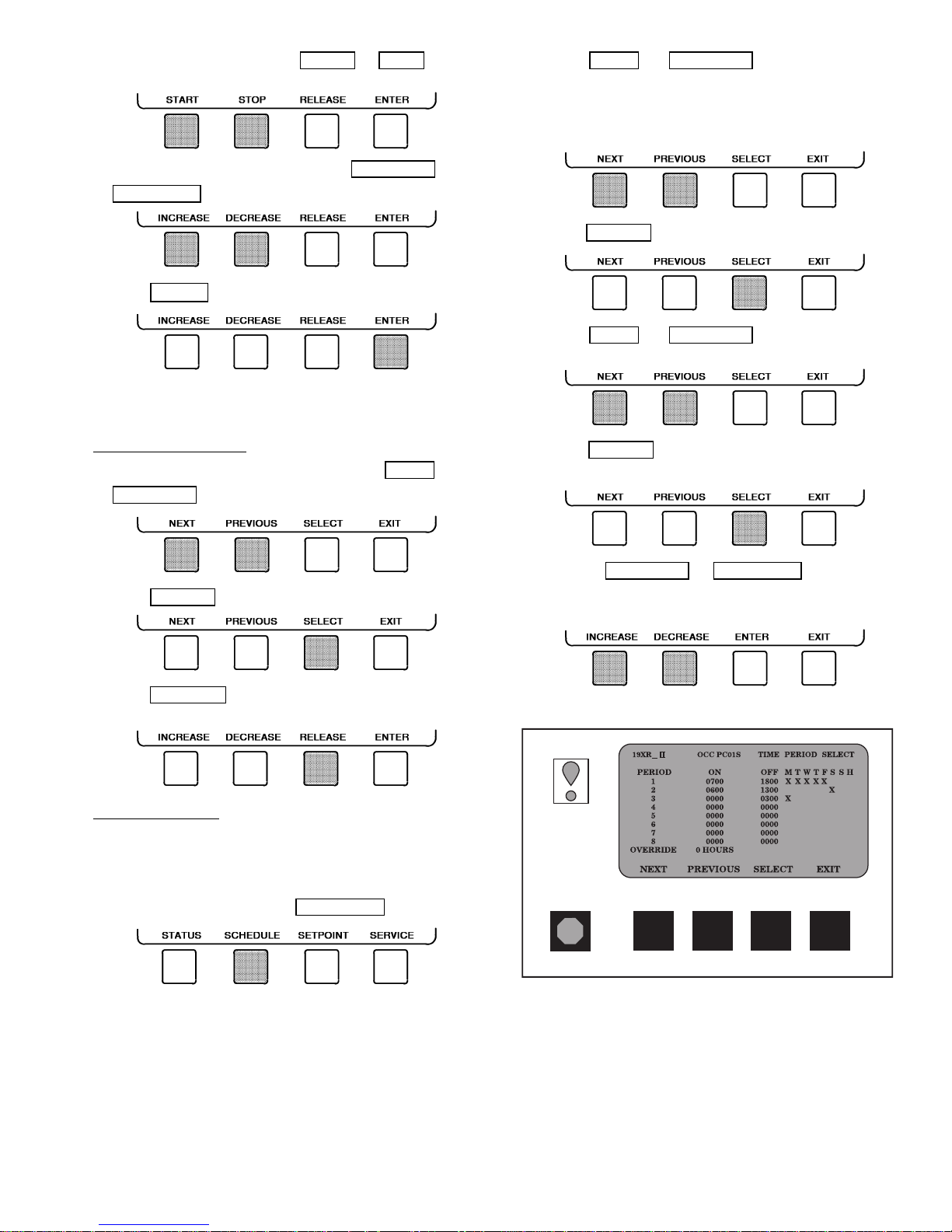
TIME SCHEDULE OPERATION (Fig. 17)
1. On the Menu screen, press SCHEDULE
.
5. Press SELECT to access the highlighted period or
override.
6. a. Press INCREASE or DECREASE to change the
time values. Override values are in one-hour increments, up to 4 hours.
Fig. 17 — Example of Time Schedule
Operation Screen
19
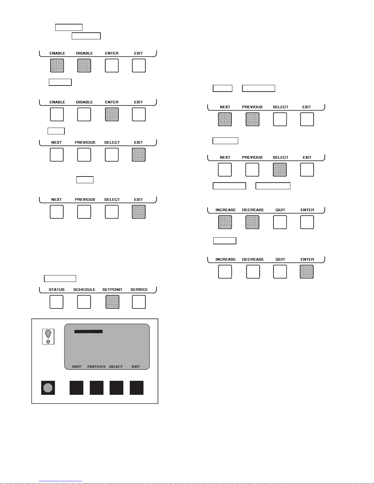
b. Press ENABLE to select days in the day-of-week
fields. Press DISABLE
to eliminate days from the
period.
7. Press ENTER to register the values and to move
horizontally (left to right) within a period.
8. Press EXIT to leave the period or override.
9. Either return to Step 4 to select another period or
override, or press EXIT
again to leave the current time
schedule screen and save the changes.
2. There are 5 set points on this screen: BASE DEMAND
LIMIT ,LCW SETPOINT (leaving chilled water set point),
ECW SETPOINT (entering chilled water set point), ICE
BUILD SETPOINT, and TOWER FAN HIGH SETPOINT. Only one of the chilled water set points can be
active at one time. The set point that is active is determined from the SERVICE menu. See the Service Operation section, page 43. The ice build (ICE BUILD) function is also activated and configured from the SERVICE
menu.
3. Press NEXT
or PREVIOUS to highlight the desired
set point entry.
4. Press SELECT to modify the highlighted set point.
5. Press INCREASE or DECREASE to change the selected set point value.
10. The Holiday Designation (HOLIDEF table) may be found
in the Service Operation section, page 43. The month,
day, and duration for the holiday must be assigned. The
Broadcast function in the BRODEF table also must be
enabled for holiday periods to function.
TO VIEW AND CHANGE SET POINTS (Fig. 18)
1. To view the SETPOINT table, from the MENU screen
press SETPOINT
.
19XR_II
SETPOINT
Base Demand Limit
Control Point
LCW Setpoint
ECW Setpoint
ICE BUILD Setpoint
Tower Fan High Setpoint
SETPOINT SELECT
100%
50.0 F
60.0 F
40.0 F
85.0 F
6. Press ENTER to save the changes and return to the
previous screen.
SERVICE OPERATION — To view the menu-driven programs available for Service Operation, see Service Operation section, page 43. For examples of CVC display screens,
see Table 2.
Fig. 18 — Example of Set Point Screen
20
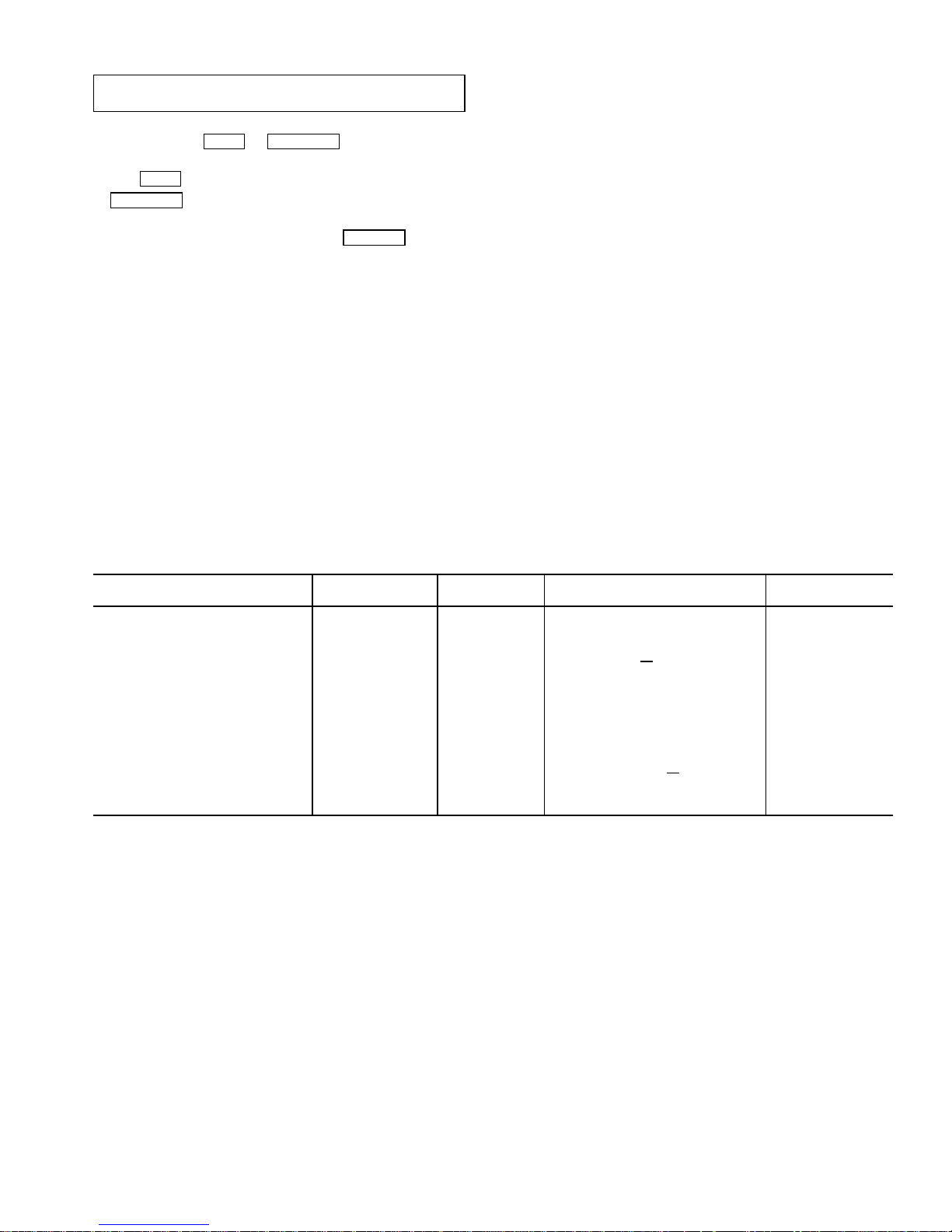
Table 2 — CVC Display Data
IMPORTANT: The following notes apply to all Table 2
examples.
1. Only 12 lines of information appear on theCVCscreen at any one
time. Press the NEXT
point or to view items below or above the current screen. Press
the NEXT
PREVIOUS
2. Toaccess the information shown in Examples 9 through 21, enter
your 4-digit password after pressing the SERVICE
no softkeys are pressed for 15 minutes, the CVC automatically
logs off (to prevent unrestricted access to PIC II controls) and reverts to the default screen. If this happens, you must reenter your
password to access the tables shown in Examples 9 through 21.
3. Termsin the Description column of these tables are listed as they
appear on the CVC screen.
4. The CVC may be configured in English or Metric (SI) units using
the CVC CONFIGURATION screen. See the Service Operation
section, page 43, for instructions on making this change.
5. The items in the Reference Point Name column
the CVC screen
Building Supervisor (BS) software. They are listed in these tables
as a convenience to the operator if it is necessary to cross referenceCCN/BS documentation oruse CCN/BS programs.For more
information, see the 19XR CCN literature.
softkey twice to page forward; press the
softkey twice to page back.
. They are data or variable names used in CCN or
or PREVIOUS softkey to highlight a
softkey. If
do not appear on
6. Reference Point Names shown in these tables in all capital letters
can beread by CCN andBS software. Of thesecapitalized names,
those preceded by a dagger can also be changed (that is, written
to) by the CCN, BS, and the CVC. Capitalized Reference Point
Names preceded by two asterisks can be changed only from the
CVC. Reference Point Names in lower case type can be viewed
by CCN or BS only by viewing the whole table.
7. Alarms and Alerts:An asterisk
screen
indicates that the chiller is in an alarm state; an exclamation point in the far right field of the CVC screen indicates an alert
state. The asterisk (or exclamation point) indicates that the value
on that line has exceeded (or is approaching) a limit. For more
information on alarms and alerts, see the Alarms and Alerts
section, page 14.
CCN — Carrier Comfort Network
CHW — Chilled Water
CHWR — Chilled Water Return
CHWS — Chilled Water Supply
CVC — Chiller Visual Control
CT — Current Transformer
ECW — Entering Chilled Water
HGBP — Hot Gas Bypass
ISM — Integrated Starter Module
LCW — Leaving Chilled Water
LRA — Locked Rotor Amps
mA — Milliamps
P—Pressure
SS — Solid State
T—Temperature
VFD — Variable Frequency Drive
WSM — Water System Manager
in the far right field of a CVC status
LEGEND
EXAMPLE 1 — CVC DEFAULT SCREEN
The following data is displayed in the CVC Default screen.
DESCRIPTION RANGE UNITS
(PRIMARY MESSAGE)
(SECONDARY MESSAGE)
(DATE AND TIME)
Compressor Ontime 0-500000.0 HOURS C
Entering Chilled Water −40-245 DEG F ECW CHW IN
Leaving Chilled Water −40-245 DEG F LCW CHW OUT
Evaporator Temperature −40-245 DEG F ERT EVAP REF
Entering Condenser Water −40-245 DEG F ECDW CDW IN
Leaving Condenser Water −40-245 DEG F LCDW CDW OUT
Condenser Temperature −40-245 DEG F CRT COND REF
Oil Pressure 0-420 PSI OILPD OILPRESS
Oil Sump Temp −40-245 DEG F OILT OIL TEMP
Average Line Current 0-999 % AMPS
NOTE: The last three entries are used to indicate operating mode to the PIC II. These values may be forced by the CVC only.
0-1 CCN
0-1 LOCAL
0-1 RESET
REFERENCE POINT NAME
(ALARM HISTORY)
HRS
% AMPS %
DISPLAY
21
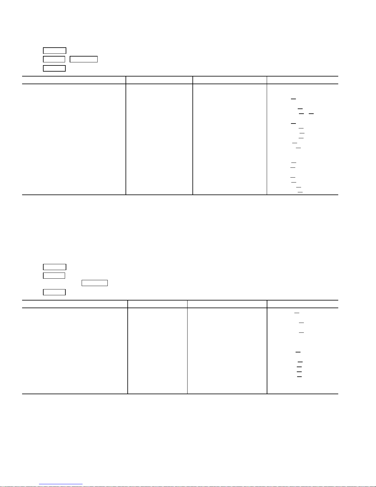
Table 2 — CVC Display Data (cont)
EXAMPLE 2 — MAINTSTAT DISPLAY SCREEN
To access this display from the CVC default screen:
1. Press MENU
2. Press STATUS
3. Press SELECT
Control Mode NOTE 1 NOTE 1 MODE
Run Status NOTE 2 NOTE 2 STATUS
Start Inhibit Timer 0-15 min T
Occupied ? 0/1 NO/YES OCC
System Alert/Alarm 0-2 NOTE 3 SYS
*Chiller Start/Stop 0/1 STOP/START CHIL S S
*Remote Start Contact 0/1 OFF/ON REMCON
Temperature Reset −30-30 DEG F T
*Control Point 10-120 DEG F LCW STPT
Chilled Water Temp −40-245 DEG F CHW
*Active Demand Limit 40-100 % DEM LIM
Average Line Current 0-999 % % AMPS
Motor Percent Kilowatts 0-999 % KW
Auto Demand Limit Input 4-20 mA AUTODEM
Auto Chilled Water Reset 4-20 mA AUTORES
Remote Reset Sensor −40-245 DEG F R
Total Compressor Starts 0-99999 c starts
Starts in 12 Hours 0-8 STARTS
Compressor Ontime 0-500000.0 HOURS c
*Service Ontime 0-32767 HOURS S HRS
Ice Build Contact 0-1 OPEN/CLOSE ICE
Refrigerant Leak Sensor 0-20 mA REF LEAK
NOTES:
1. Reset, Off, Local, CCN
2. Timeout, Ready, Recycle, Prestart, Start-up, Ramping, Running, Demand, Override, Shutdown, Trippout, Pumpdown, Lockout
3. Normal, Alert, Alarm
4. All variables with capital letter point names are available for CCN read operation. Those shown with (*) support write operations for all CCN
devices.
.
( MAINSTAT will be highlighted).
.
DESCRIPTION STATUS UNITS POINT
START
ALM
RESET
TMP
P
RESET
hrs
CON
EXAMPLE3—STARTUP DISPLAY SCREEN
To access this display from the CVC default screen:
1. Press MENU
2. Press STATUS
3. Scroll down to highlight STARTUP
4. Press SELECT
Actual Guide Vane Pos 0-100 % GV
**Chilled Water Pump 0-1 OFF/ON CHWP
Chilled Water Flow 0-1 NO/YES CHW FLOW
**Condenser Water Pump 0-1 OFF/ON CDP
Condenser Water Flow 0-1 NO/YES CDW
Oil Pump Relay 0-1 OFF/ON OILR
**Oil Pump Delta P −6.7-200 ^PSI OILPD
Compressor Start Relay 0-1 OFF/ON CMPR
Compressor Start Contact 0-1 OPEN/CLOSED ICR
Starter Trans Relay 0-1 OFF/ON CMPTRANS
Compressor Run Contact 0-1 OPEN/CLOSED RUN AUX
**Tower Fan Relay Low 0-1 OFF/ON TFR
**Tower Fan Relay High 0-1 OFF/ON TFR HIGH
Starter Fault 0-1 ALARM/NORMAL STR FLT
Spare Safety Input 0-1 ALARM/NORMAL SAFETY
Shunt Trip Relay 0-1 OFF/ON TRIPR
Starter Fault Status 0-255 STRSTAT
NOTE:All variables with CAPITALLETTER point names are available for CCN read operation. Those shown with (**) shall support write operations
for the CVC only.
.
.
.
.
DESCRIPTION STATUS UNITS POINT
ACT
FLOW
AUX
LOW
22
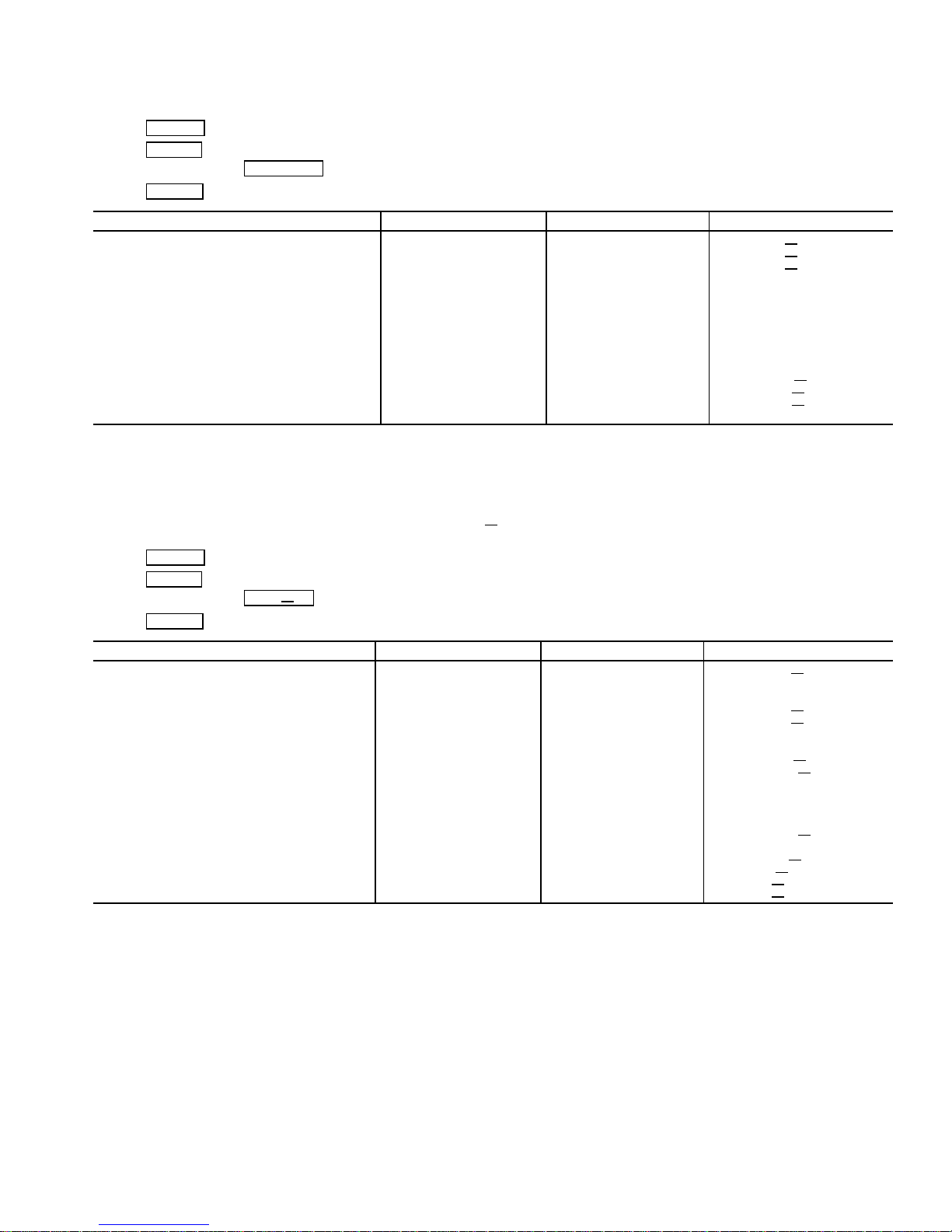
Table 2 — CVC Display Data (cont)
EXAMPLE 4 — COMPRESS DISPLAY SCREEN
To access this display from the CVC default screen:
1. Press MENU
2. Press STATUS
3. Scroll down to highlight COMPRESS .
4. Press SELECT
Actual Guide Vane Pos 0-100 % GV
Guide Vane Delta 0-100 % GV DELTA
**Target Guide Vane Pos 0-100 % GV
Oil Sump Temp −40-245 DEG F OILT
**Oil Pump Delta P −6.7-200 DEG F OILPD
Comp Discharge Temp −40-245 DEG F CMPD
Comp Thrust Brg Temp −40-245 DEG F MTRB
Comp Motor Winding Temp −40-245 DEG F MTRW
Spare Temperature 1 −40-245 DEG F SPARE1
Spare Temperature 2 −40-245 DEG F SPARE2
Oil Heater Relay 0/1 OFF/ON OILH
Diffuser Actuator 0-100 % DIFF
**Target VFD Speed 0-110 % VFD OUT
**Actual VFD Speed 0-100 % VFD
Surge Protection Counts 0-5 spc
NOTE:All variables with CAPITALLETTER point names are available for CCN read operation. Those shown with (**) shall support write operations
for the CVC only.
.
.
.
DESCRIPTION STATUS UNITS POINT
ACT
TRG
ACT
ACT
EXAMPLE 5 — HEAT
To access this display from the CVC default screen:
1. Press MENU
2. Press STATUS
3. Scroll down to highlight HEAT
4. Press SELECT
**Chilled Water Delta P −6.7-420 PSI CHW
Entering Chilled Water −40-245 DEG F ECW
Leaving Chilled Water −40-245 DEG F LCW
Chilled Water Delta T −6.7-420 ^ F CHW
Chill Water Pulldown/Min −20-20 ^ F CHW
Evaporator Refrig Temp −40-245 DEG F ERT
**Evaporator Pressure −6.7-420 PSI ERP
Evaporator Approach 0-99 ^ F EVAP
**Condenser Water Delta P −6.7-420 PSI COND PD
Entering Condenser Water −40-245 DEG F ECDW
Leaving Condenser Water −40-245 DEG F LCDW
Condenser Refrig Temp −40-245 DEG F CRT
**Condenser Pressure −6.7-420 PSI CRP
Condenser Approach 0-99 ^ F COND
Hot Gas Bypass Relay 0/1 OFF/ON HGBR
Surge/HGBP Active ? 0/1 NO/YES SHG
Active Delta P 0-200 PSI dp a
Active Delta T 0-200 DEG F dt a
Surge/HGBP Delta T 0-200 DEG F dt
NOTE:All variables with CAPITALLETTER point names are available for CCN read operation. Those shown with (**) shall support write operations
for the CVC only.
.
.
EX .
.
DESCRIPTION STATUS UNITS POINT
EX DISPLAY SCREEN
PD
DT
PULL
APP
APP
ACT
c
23
Table 2 — CVC Display Data (cont)
EXAMPLE 6 — POWER DISPLAY SCREEN
To access this display from the CVC default screen:
1. Press MENU
2. Press STATUS
3. Scroll down to highlight POWER .
4. Press SELECT
Average Line Current 0-999 % %
Actual Line Current 0-99999 AMPS AMP A
Average Line Voltage 0-999 % VOLT
Actual Line Voltage 0-99999 VOLTS VOLT A
Power Factor 0.0-1.0 PF
Motor Kilowatts 0-99999 kW KW
Motor Kilowatt-Hours 0-99999 kWH KWH
Demand Kilowatts 0-99999 kWH DEM KWH
Line Current Phase 1 0-99999 AMPS AMPS
Line Current Phase 2 0-99999 AMPS AMPS 2
Line Current Phase 3 0-99999 AMPS AMPS
Line Voltage Phase 1 0-99999 VOLTS VOLTS 1
Line Voltage Phase 2 0-99999 VOLTS VOLTS 2
Line Voltage Phase 3 0-99999 VOLTS VOLTS
Ground Fault Phase 1 0-999 AMPS GF 1
Ground Fault Phase 2 0-999 AMPS GF 2
Ground Fault Phase 3 0-999 AMPS GF
Frequency 0-99 Hz FREQ
I2T Sum Heat-Phase 1 0-200 % HEAT1SUM
I2T Sum Heat-Phase 2 0-200 % HEAT2SUM
I2T Sum Heat-Phase 3 0-200 % HEAT3SUM
NOTE: All variables with CAPITAL LETTER point names are available for CCN read operation.
.
.
.
DESCRIPTION STATUS UNITS POINT
AMPS
P
A
1
3
3
3
EXAMPLE7—ISM
To access this display from the CVC default screen:
1. Press MENU
2. Press STATUS
3. Scroll down to highlight ISM STAT .
4. Press SELECT
ISM Fault Status 0-223 ISMFLT
Single Cycle Dropout 0-1 NORMAL/ALARM CYCLE
Phase Loss 0-1 NORMAL/ALARM PH
Overvoltage 0-1 NORMAL/ALARM OV VOLT
Undervoltage 0-1 NORMAL/ALARM UN VOLT
Current Imbalance 0-1 NORMAL/ALARM AMP
Voltage Imbalance 0-1 NORMAL/ALARM VOLT UNB
Overload Trip 0-1 NORMAL/ALARM OVERLOAD
Locked Rotor Trip 0-1 NORMAL/ALARM LRATRIP
Starter LRA Trip 0-1 NORMAL/ALARM SLRATRIP
Ground Fault 0-1 NORMAL/ALARM GRND
Phase Reversal 0-1 NORMAL/ALARM PH REV
Frequency Out of Range 0-1 NORMAL/ALARM FREQFLT
ISM Power on Reset 0-1 NORMAL/ALARM ISM
Phase 1 Fault 0-1 NORMAL/ALARM PHASE 1
Phase 2 Fault 0-1 NORMAL/ALARM PHASE 2
Phase 3 Fault 0-1 NORMAL/ALARM PHASE
ICR Start Complete 0-1 FALSE/TRUE START OK
IM Start/Run Fault 0-1 NORMAL/ALARM 1M FLT
2M Start/Run Fault 0-1 NORMAL/ALARM 2M
Pressure Trip Contact 0-1 NORMAL/ALARM PRS TRIP
Starter Fault 0-1 NORMAL/ALARM STRT
Motor Amps Not Sensed 0-1 NORMAL/ALARM NO AMPS
Starter Acceleration Fault 0-1 NORMAL/ALARM ACCELFLT
High Motor Amps 0-1 NORMAL/ALARM HIGHAMPS
ICR Stop Complete 0-1 FALSET/TRUE STOP
1M/2M Stop Fault 0-1 NORMAL/ALARM 1M2MSTOP
Motor Amps When Stopped 0-1 NORMAL/ALARM AMPSTOP
Hardware Failure 0-1 NORMAL/ALARM HARDWARE
NOTE: All variables with CAPITAL LETTER point names are available for CCN read operation.
.
.
.
DESCRIPTION STATUS UNITS POINT
STAT SCREEN
LOSS
UNB
FLT
POR
FLT
FLT
OK
1
3
24
Table 2 — CVC Display Data (cont)
EXAMPLE 8 — SET POINT DISPLAY SCREEN
To access this display from the CVC default screen:
1. Press MENU
2. Press SETPOINT
3. Press SELECT
Base Demand Limit 40-100 % DLM 100
Control Point
LCW Set Point 10-120 DEG F lcw
ECW Set Point 15-120 DEG F ecw sp 60.0
Ice Build Set Point 15-60 DEG F ice
Tower Fan High Set Point 55-105 DEG F tf2 sp 75
NOTE: All variables are available for CCN read operation; forcing shall not be supported on set point screens.
To access this display from the CVC default screen:
1. Press MENU
2. Press SERVICE
3. Scroll down to highlight CONTROL ALGORITHM STATUS .
4. Press SELECT
5. Scroll down to highlight CAPACITY
.
(Base Demand Limit will be highlighted).
.
DESCRIPTION STATUS UNITS POINT DEFAULT
sp 50.0
sp 40.0
EXAMPLE 9 — CAPACITY DISPLAY SCREEN
.
.
.
.
DESCRIPTION STATUS UNITS POINT
Entering Chilled Water −40-245 DEG F ECW
Leaving Chilled Water −40-245 DEG F LCW
Capacity Control
Control Point 10-120 DEG F ctrlpt
Control Point Error −99-99 DEG F cperr
ECW Delta T −99-99 DEG F ecwdt
ECW Reset −99-99 DEG F ecwres
LCW Reset −99-99 DEG F lcwres
Total Error + Resets −99-99 DEG F error
Guide Vane Delta −2-2 % gvd
Target Guide Vane Pos 0-100 % GV
Actual Guide Vane Pos 0-100 % GV ACT
Target VFD Speed 0-100 % VFD
ACTUAL VFD Speed 0-100 % VFD ACT
VFD Gain 0.1-1.5 vfd gain
Demand Inhibit Active 0-1 NO/YES DEM
Amps/kW Ramp 0-100 % DMD RAMP
NOTE: All variables with CAPITAL LETTER point names are available for CCN read operation; forcing shall not be supported on maintenance
screen.
TRG
IN
INH
25
Table 2 — CVC Display Data (cont)
EXAMPLE 10 — OVERRIDE DISPLAY SCREEN
To access this display from the CVC default screen:
1. Press MENU
2. Press SERVICE
3. Scroll down to highlight CONTROL ALGORITHM STATUS .
4. Press SELECT
5. Scroll down to highlight OVERRIDE
Comp Motor Winding Temp −40-245 DEG F MTRW
Comp Motor Temp Override 150-200 DEG F mt
Condenser Pressure 0-420 PSI CRP
Cond Press Override 90-180 PSI cp over
Evaporator Refrig Temp −40-245 DEG F ERT
Evap Ref Override Temp 2-45 DEG F rt
Comp Discharge Temp −40-245 DEG F CMPD
Comp Discharge Alert 125-200 DEG F cd
Comp Thrust Brg Temp −40-245 DEG F MTRB
Comp Thrust Brg Alert 165-185 DEG F tb alert
Actual Superheat −20-99 DEG F SUPRHEAT
Superheat Required 6-99 ^ F SUPR
Condenser Refrig Temp −40-245 ^ F CRT
NOTE: All variables with CAPITAL LETTER point names are available for CCN read operation; forcing shall not be supported on maintenance
screens.
.
.
.
.
DESCRIPTION STATUS UNITS POINT
over
over
alert
REQ
EXAMPLE 11 — LL
To access this display from the CVC default screen:
1. Press MENU
2. Press SERVICE
3. Scroll down to highlight CONTROL ALGORITHM STATUS .
4. Press SELECT
5. Scroll down to highlight LL
Lead Lag Control
LEAD/LAG: Configuration NOTE 1 leadlag
Current Mode NOTE 2 llmode
Load Balance Option 0/1 DSABLE/ENABLE loadbal
LAG Start Time 2-60 MIN lagstart
LAG Stop Time 2-60 MIN lagstop
PRESTART FAULT Time 2-30 MIN preflt
Pulldown: Delta T/Min x.xx ^ DEG pull
Satisfied? 0/1 NO/YES pull
LEAD CHILLER in Control 0/1 NO/YES leadctrl
LAG CHILLER: Mode NOTE 3 lagmode
Run Status NOTE 4 lagstat
Start/Stop NOTE 5 lag
Recovery Start Request 0/1 NO/YES lag
STANDBY CHILLER: Mode NOTE 3 stdmode
Run Status NOTE 4 stdstat
Start/Stop NOTE 5 Std
Recovery Start Request 0/1 NO/YES std rec
Spare Temperature 1 −40-245 DEG F SPARE1
Spare Temperature 2 −40-245 DEG F SPARE2
NOTES:
1. DISABLE, LEAD, LAG, STANDBY, INVALID
2. DISABLE, LEAD, LAG, STANDBY, RECOVERY, CONFIG
3. Reset, Off, Local, CCN
4. Timeout, Ready, Recycle, Prestart, Startup Ramping, Running, Demand, Override, Shutdown, Trippout, Pumpdown, Lockout
5. Stop, Start, Retain
6. All variables with CAPITALLETTER point names are available for CCN read operation; forcing shall not be supported on maintenance screens.
.
.
.
MAINT. .
DESCRIPTION STATUS UNITS POINT
MAINT DISPLAY SCREEN
dt
sat
s s
rec
s s
26
Table 2 — CVC Display Data (cont)
EXAMPLE 12 — ISM HIST DISPLAY SCREEN
To access this display from the CVC default screen:
1. Press MENU
2. Press SERVICE
3. Scroll down to highlight CONTROL ALGORITHM STATUS .
4. Press SELECT
5. Scroll down to highlight ISM
ISM FAULT HISTORY
Values At Last Fault:
Line Current Phase 1 0-99999 AMPS AMPS
Line Current Phase 2 0-99999 AMPS AMPS
Line Current Phase 3 0-99999 AMPS AMPS 3F
Line Voltage Phase 1 0-99999 VOLTS VOLTS 1F
Line Voltage Phase 2 0-99999 VOLTS VOLTS
Line Voltage Phase 3 0-99999 VOLTS VOLTS 3F
Ground Fault Phase 1 0-999 AMPS GF 1F
Ground Fault Phase 2 0-999 AMPS GF
Ground Fault Phase 3 0-999 AMPS GF 3F
I2T Sum Heat-Phase 1 0-200 % HEAT1SUMF
I2T Sum Heat-Phase 2 0-200 % HEAT2SUMF
I2T Sum Heat-Phase 3 0-200 % HEAT3SUMF
Phase 1 Faulted? 0/1 NO/YES PH1
Phase 2 Faulted? 0/1 NO/YES PH2
Phase 3 Faulted? 0/1 NO/YES PH3 FLT
Line Frequency 0-99 Hz FREQ
ISM Fault Status 0-9999 ISM STAT
NOTE: All variables with CAPITAL LETTER point names are available for CCN read operation; forcing shall not be supported on maintenance
screens.
.
.
.
HIST .
DESCRIPTION STATUS UNITS POINT
2F
FLT
FLT
F
1F
2F
2F
EXAMPLE 13 — WSMDEFME DISPLAY SCREEN
To access this display from the CVC default screen:
1. Press MENU
2. Press SERVICE
3. Scroll down to highlight CONTROL ALGORITHM STATUS
4. Press SELECT
5. Scroll down to highlight WSMDEFME
WSM Active? 0/1 NO/YES WSMSTAT
Chilled Water Temp 0.0-99.9 DEG F CHWTEMP
Equipment Status 0/1 OFF/ON CHLRST
Commanded State XXXXXXXX TEXT CHLRENA
CHW setpt Reset Value 0.0-25.0 DEG F CHWRVAL
Current CHW Set Point 0.0-99.9 DEG F CHWSTPT
NOTE: All variables with CAPITAL LETTER point names are available for CCN read operation; forcing shall not be supported on maintenance
screens.
.
.
.
.
.
DESCRIPTION STATUS UNITS POINT
27
Table 2 — CVC Display Data (cont)
EXAMPLE 14 — NET OPT DISPLAY SCREEN
To access this display from the CVC default screen:
1. Press MENU
2. Press SERVICE
3. Scroll down to highlight EQUIPMENT CONFIGURATION .
4. Press SELECT
5. Scroll down to highlight NET
Loadshed Function
Group Number 0-99 ldsgrp 0
Demand Limit Decrease 0-60 % ldsdelta 20
Maximum Loadshed Time 0-120 MIN maxldstm 60
CCN Occupancy Config:
Schedule Number 3-99 occpcxxe 3
Broadcast Option 0-1 DSABLE/ENABLE occbrcst DSABLE
Alarm Configuration
Re-alarm Time 0-1440 MIN 30
Alarm Routing 0-1 10000000
NOTE: No variables are available for CCN read or write operation.
.
.
.
OPT .
DESCRIPTION STATUS UNITS POINT DEFAULT
EXAMPLE 15 — ISM
To access this display from the CVC default screen:
1. Press MENU
2. Press SERVICE
3. Scroll down to highlight ISM (STARTER) CONFIG DATA
4. Press SELECT
5. Scroll down to highlight ISM
Starter Type 0-2 starter 1
(0 = Full, 1 = Red, 2 = SS/VFD)
Motor Rated Line Voltage 200-13200 VOLTS v
Volt Transformer Ratio:1 1-33 vt
Overvoltage Threshold 105-115 % overvolt 115
Undervoltage Threshold 85-95 % undvolt 85
Over/Under Volt Time 1-10 SEC uvuntime 5
Voltage % Imbalance 1-10 % v
Voltage Imbalance Time 1-10 SEC v
Motor Rated Load Amps 10-5000 AMPS a fs 200
Motor Locked Rotor Trip 100-60000 AMPS motor lr 1000
Locked Rotor Start Delay 1-10 cycles lrdelay 5
Starter LRA Rating 100-60000 AMPS start
Motor Current CT Ratio:1 10-1000 ct turns 100
Current % Imbalance 5-40 % c
Current Imbalance Time 1-10 SEC c time 5
3 Grnd Fault CT’s? (1 = No) 0-1 NO/YES gf phase YES
Ground Fault CT Ratio:1 150 gf
Ground Fault Current 1-20 AMPS gf amps 15
Ground Fault Start Delay 1-20 cycles gf
Ground Fault Persistence 1-10 cycles gf pers 5
Single Cycle Dropout 0/1 DSABLE/ENABLE cycdrop DSABLE
Frequency = 60 Hz? (No = 50) 0/1 NO/YES freq YES
Line Frequency Faulting 0/1 DSABLE/ENABLE freq
.
.
.
.
CONF .
DESCRIPTION STATUS UNITS POINT DEFAULT
CONF DISPLAY SCREEN
fs 460
rat 1
unbal 5
time 5
lr 2000
unbal 15
ctr 150
delay 10
en DSABLE
28
Table 2 — CVC Display Data (cont)
EXAMPLE 16 — OPTIONS DISPLAY SCREEN
To access this display from the CVC default screen:
1. Press MENU
2. Press SERVICE
3. Scroll down to highlight EQUIPMENT SERVICE .
4. Press SELECT
5. Scroll down to highlight OPTIONS
Auto Restart Option 0/1 DSABLE/ENABLE astart DSABLE
Remote Contacts Option 0/1 DSABLE/ENABLE r
Soft Stop Amps Threshold 40-100 % softstop 100
Surge/Hot Gas Bypass
Surge Limit/HGBP Option 0/1 srg
Select: Surge = 0, HGBP = 1
Min. Load Point (T1/P1)
Surge/HGBP Delta T1 0.5-15 ^ F hgb
Surge/HGBP Delta P1 30-170 PSI hgb
Full Load Point (T2/P2)
Surge/HGBP Delta T2 0.5-15 ^ F hgb dt2 10
Surge/HGBP Delta P2 50-170 PSI hgb
Surge/HGBP Deadband 0.5-3 ^ F hgb dp 1
Surge Protection
Surge Delta % Amps 5-15 % surge
Surge Time Period 7-10 MIN surge
Ice Build Control
Ice Build Option 0/1 DSABLE/ENABLE ibopt DSABLE
Ice Build Termination 0-2 ibterm 0
0 = Temp, 1 = Contacts, 2 = Both
Ice Build Recycle 0/1 DSABLE/ENABLE ibrecyc DSABLE
Refrigerant Leak Option 0/1 DSABLE/ENABLE DSABLE
Refrigerant Leak Alarm mA 4-20 mA REF
NOTE: No variables are available for CCN read or write operation.
.
.
.
.
DESCRIPTION STATUS UNITS POINT DEFAULT
contact DSABLE
hgbp 0
dt1 1.5
dp1 50
dp2 85
a10
t8
LEAK 20
EXAMPLE 17 — SETUP1 DISPLAY SCREEN
To access this display from the CVC default screen:
1. Press MENU
2. Press SERVICE
3. Scroll down to highlight EQUIPMENT SERVICE .
4. Press SELECT
5. Scroll down to highlight SETUP1
Comp Motor Temp Override 150-200 DEG F mt
Cond Press Override 90-165 PSI cp over 125
Comp Discharge Alert 125-200 DEG F cd
Comp Thrust Brg Alert 165-185 DEG F tb alert 175
Chilled Medium 0/1 WATER/BRINE medium WATER
Chilled Water Deadband .5-2.0 ^F cw
Evap Refrig Trippoint 0.0-40.0 DEG F ert
Refrig Override Delta T 2.0-5.0 ^F ref over 3
Condenser Freeze Point −20 - 35 DEG F cdfreeze 34
Evap Flow Delta P Cutout 0.5 - 50.0 PSI evap
Cond Flow Delta P Cutout 0.5 - 50.0 PSI cond cut 5.0
Water Flow Verify Time 0.5-5 MIN wflow
Oil Press Verify Time 15-300 SEC oilpr t40
Recycle control
Recycle Restart Delta T 2.0-10.0 DEG F rcycr
Recycle Shutdown Delta 0.5-4.0 DEG F rcycs dt 1
SPARE ALERT/ALARM ENABLE
Disable=0, Lo=1/3,Hi=2/4
Spare Temp #1 Enable 0.4 sp1
Spare Temp #1 Limit −40-245 DEG F sp1 lim 245
Spare Temp #2 Enable 0-4 sp2
Spare Temp #2 Limit -40-245 DEG F sp2 lim 245
NOTE: No variables are available for CCN read operation; forcing shall not be supported on service screens.
.
.
.
.
DESCRIPTION STATUS UNITS POINT DEFAULT
over 200
alert 200
db 1.0
trip 33
cut 5.0
t5
dt 5
en 0
en 0
29
Table 2 — CVC Display Data (cont)
EXAMPLE 18 — SETUP2 DISPLAY SCREEN
To access this display from the CVC default screen:
1. Press MENU
2. Press SERVICE
3. Scroll down to highlight EQUIPMENT SERVICE .
4. Press SELECT
5. Scroll down to highlight SETUP2
Capacity Control
Proportional Inc Band 2-10 gv
Proportional DEC Band 2-10 gv dec 6.0
Proportional ECW Gain 1-3 gv
Guide Vane Travel Limit 30-100 % gv
Diffuser Control
Diffuser Option 0-1 DSABLE/ENABLE diff
Guide Vane 25% Load Pt 0-78 % gv
Diffuser 25% Load 0-100 % df 25 0
Guide Vane 50% Load Pt 0-78 % gv
Diffuser 50% Load Pt 0-100 % df 50 0
Guide Vane 75% Load Pt 0-78 % gv 75 75
Diffuser 75% Load Pt 0-100 % df
Diffuser Full Span mA 15-22 mA diff ma 18
VFD Speed Control
VFD Option 0/1 DSABLE/ENABLE vfd
VFD Gain 0.1-1.5 vfd gain 0.75
VFD Increase Step 1-5 % vfd
VFD Minimum Speed 65-100 % vfd min 70
VFD Maximum speed 90-110 % vfd max 100
NOTE: No variables are available for CCN read operation; forcing shall be supported on service screens.
.
.
.
.
DESCRIPTION STATUS UNITS POINT DEFAULT
inc 6.5
ecw 2.0
lim 80
opt DSABLE
25 25
50 50
75 0
opt DSABLE
step 2
EXAMPLE 19 − LEADLAG DISPLAY SCREEN
To access this display from the CVC default screen:
1. Press MENU
2. Press SERVICE
3. Scroll down to highlight EQUIPMENT SERVICE
4. Press SELECT
5. Scroll down to highlight LEADLAG
Lead Lag Control
LEAD/LAG Configuration 0-3 leadlag 0
DSABLE=0, LEAD=1,
LAG=2, STANDBY=3
Load Balance Option 0/1 DSABLE/ENABLE load/bal DSABLE
Common Sensor Option 0/1 DSABLE/ENABLE commsens DSABLE
LAG Percent Capacity 25-75 % lag
LAG Address 1-236 lag add 92
LAG START Timer 2-60 MIN lagstart 10
LAG STOP Timer 2-60 MIN lagstop 10
PRESTART FAULT Timer 2-30 MIN preflt 5
STANDBY Chiller Option 0/1 DSABLE/ENABLE stndopt DSABLE
STANDBY Percent Capacity 25-57 % stnd
STANDBY Address 1-236 stnd
NOTE: No variables are available for CCN read or write operation.
.
.
.
.
.
DESCRIPTION STATUS UNITS POINT DEFAULT
per 50
per 50
add 93
30
 Loading...