

Canon LBP-1760 Service manual

SERVICE
MANUAL
REVISION 0
COPYRIGHT 1998 CANON INC. CANON LBP-1760 REV. 0 MAY 1998 PRINTED IN JAPAN (IMPRIME AU JAPON)
RY8-1387-000
MAY 1998
LBP-1760

COPYRIGHT © 1998 CANON INC
Printed in Japan
Imprimé au Japon
Use of this manual should be
strictly supervised to avoid
disclosure of confidential
information.
Prepared by
PERIPHERAL PRODUCTS QUALITY ADVANCEMENT DIV.
PERIPHERAL PRODUCTS TECHNICAL DOCUMENTATION DEPT.
CANON INC.
5-1, Hakusan 7-chome, Toride-City, Ibaraki-Pref. 302-8501, Japan

PREFACE
This Service Manual contains basic information required for after-sales service of the laser beam
printer LBP-1760 (here after referred to as the “printer”). This information is vital to the service
technician in maintaining the high print quality and performance of the printer.
The paper feeder, envelope feeder and duplexing unit, which are prepared for the printer as
options, are described in this manual.
This manual consists of the following chapters:
Chapter 1: Product information
Features, specifications and installation
Chapter 2: Operation and Timing
A description of the operating principles and timing sequences of the electrical and
mechanical systems
Chapter 3: The Mechanical System
Explanation of mechanical operation, disassembly, reassembly and adjustment procedures
Chapter 4: Troubleshooting
Troubleshooting procedures, reference values and adjustments, maintenance and
servicing, etc.
Appendix: General timing chart, general circuit diagram, etc.
Information in this manual is subject to change as the product is improved or redesigned. All
relevant information in such cases will be supplied in the Service Information Bulletins.
A thorough understanding of this printer, based on information in this Manual and Service
Information bulletins, is required for maintaining its performance and for locating and repairing
the causes of malfunctions.

DTP system
This manual was produced on an Apple PowerMacintosh 9500/200 personal computer and output by an
Apple LaserWriter 16/600 PS laser beam printer.
All graphics were produced with Macromedia FreeHand (J), and all documents and page layouts were
created with QuarkXPress (E).
The video images were captured with SONY degital video camcorder and MASS microsystems
Quickimage 24 video capture board, and modified with Adobe Photoshop (J).

CONTENTS
CHAPTER 1 PRODUCT INFORMATION
I. FEATURES ............................. 1-1
II. SPECIFICATIONS.................... 1-3
III. SAFETY INFORMATION..... 1-6
IV. PARTS OF THE PRINTER ....... 1-7
V. INSTALLATION ....................... 1-12
VI. MAINTENANCE AND
SERVICING BY THE
CUSTOMER ............................ 1-19
VII. OPERATION............................ 1-20
CHAPTER 2 OPERATION AND TIMING
CHAPTER 3 THE MECHANICAL SYSTEM
I. BASIC OPERATION................. 2-1
A. Functions.......................... 2-1
B. Basic Operation Sequences 2-2
C. Power ON Sequence........... 2-3
II. ENGINE CONTROL SYSTEM.... 2-4
A. Engine Controller PCB....... 2-4
B. Fixing Control ................... 2-10
C. High-Voltage Power Supply
Circuit............................... 2-14
D. Low-Voltage Power Supply
Circuit............................... 2-16
E. Video Interface Control ..... 2-17
F. Other Controls .................. 2-20
III. LASER/SCANNER SYSTEM..... 2-22
A. Outline.............................. 2-22
B. Laser Control Circuit......... 2-23
C. Scanner System ................ 2-26
IV. IMAGE FORMATION SYSTEM . 2-28
A. Outline.............................. 2-28
B. Printing Process ................ 2-30
V. PICK-UP/FEED SYSTEM......... 2-38
A. Outline.............................. 2-38
B. Paper Size Detection ......... 2-40
C. Cassette Pick-up................ 2-41
D. Multi-purpose Tray
Pick-up.............................. 2-44
E. Fixing and Delivery Unit.... 2-46
F. Paper Jam Detection......... 2-48
VI. VIDEO CONTROL SYSTEM...... 2-50
A. Video Controller Circuit .... 2-50
B. Adapter Circuit.................. 2-52
C. Operation Panel................. 2-55
D. Self Test............................ 2-56
VII. PAPER FEEDER...................... 2-58
A. Outline.............................. 2-58
B. Pick-up and Feeding.......... 2-59
C. Paper Jam Detection......... 2-62
VIII.ENVELOPE FEEDER ............... 2-63
A. Outline.............................. 2-63
B. Pick-up and Feeding.......... 2-64
C. Paper Jam Detection......... 2-67
IX. DUPLEXING UNIT................... 2-68
A. Outline.............................. 2-68
B. Reversing and duplexing
unit Pick-up ...................... 2-70
C. Paper Jam Detection......... 2-74
I. EXTERNALS ........................... 3-1
A. External Covers................. 3-1
B. Pick-up Module.................. 3-5
C. Cooling Fan....................... 3-6
D. Operation Panel................. 3-7
II. DRIVE SYSTEM ...................... 3-8
A. Drive Unit ......................... 3-8
B. Main Motor........................ 3-9
C. Pick-up Drive Unit............. 3-10
III. PAPER TRANSPORT SYSTEM . 3-11

A. Cassette Pick-up Roller ..... 3-11
B. Cassette Feed Roller.......... 3-11
C. Separation Roller .............. 3-12
D. Multi-purpose Tray
Pick-up Roller ................... 3-12
E. Separation Pad .................. 3-13
F. Multi-purpose Tray Unit .... 3-14
G. Registration Unit............... 3-15
H. Feed Roller Unit ................ 3-17
I. Feed Guide Unit ................ 3-18
J. Delivery Unit..................... 3-18
IV. EXPOSURE SYSTEM............... 3-19
A. Laser/Scanner Unit ........... 3-19
V. ELECTROSTATIC IMAGING/
DEVELOPING/CLEANING
SYSTEM ................................. 3-20
A. EP-52 Cartridge................. 3-20
B. Transfer Charging Roller ... 3-21
VI. FIXING SYSTEM ..................... 3-23
A. Fixing Unit ........................ 3-23
VII. PRINTED CIRCUIT BOARDS ... 3-27
A. Engine Controller PCB....... 3-27
B. Paper Size Detection PCB.. 3-28
C. Video Controller PCB......... 3-29
D. Adapter PCB...................... 3-30
VIII.PAPER FEEDER...................... 3-31
IX. ENVELOPE FEEDER ............... 3-35
X. DUPLEXING UNIT ................... 3-39
CHAPTER 4 TROUBLESHOOTING
I. PREFACE ............................... 4-1
A. Malfunction Diagnosis
Flowchart .......................... 4-1
B. Initial Check ..................... 4-4
C. Test Print.......................... 4-5
II. IMAGE DEFECTS.................... 4-10
III. PAPER JAMS
TROUBLESHOOTING .............. 4-16
IV PAPER TRANSPORT
TROUBLESHOOTING .............. 4-22
V. MALFUNCTION
TROUBLESHOOTING .............. 4-24
VI. MALFUNCTION STATUS
TROUBLESHOOTING .............. 4-25
VII. MEASUREMENT AND
ADJUSTMENT ........................ 4-34
A. Mechanical Adjustment ..... 4-34
B. Electrical Adjustment........ 4-38
C. Variable Resisters, LEDs,
Test Pins, Jumpers and
Switches on PCBs.............. 4-40
VIII.MAINTENANCE AND
SERVICING............................. 4-43
A. Periodic Replacement
Parts ................................ 4-43
B. Expected Service Life of
Consumable Parts.............. 4-43
C. Periodic Service ................ 4-43
D. Cleaning Points for
Servicing .......................... 4-44
E. Standard Tools .................. 4-46
F. Special Tools..................... 4-47
G. Printer driver tester .......... 4-48
H. Solvents and Oil List ......... 4-55
IX. LOCATION OF ELECTRICAL
PARTS.................................... 4-56
A. Switches............................ 4-56
B. Sensors ............................. 4-58
C. Clutches/Solenoids ........... 4-60
D. Motors/Others................... 4-62
E. PCBs.................................. 4-64
F. Connectors........................ 4-66

APPENDIX
I. GENERAL TIMING CHART ...... A-1
II. GENERAL CIRCUIT DIAGRAM A-3
III. LIST OF SIGNALS................... A-5
IV. MESSAGE TABLE ................... A-11


CHAPTER 1
PRODUCT INFORMATION
I. FEATURES ............................. 1-1
II. SPECIFICATIONS.................... 1-3
III. SAFETY INFORMATION..... 1-6
IV. PARTS OF THE PRINTER ....... 1-7
V. INSTALLATION ....................... 1-12
VI. MAINTENANCE AND
SERVICING BY THE
CUSTOMER ............................ 1-19
VII. OPERATION............................ 1-20


I. FEATURES
1. High speed printing
Equipped with the Intel 960HD-50 processor, this printer is compact in size and capable of
printing a maximum of 17 pages/min. (LTR).
2. Excellent image quality
Resolution of 1200/600DPI, super fine particle toner, and automatic image refinement provide
excellent image.
3. Various paper source in option
The three kinds of optional paper source, paper feeder, envelope feeder, and duplexing unit, will
meet various requirements for a user.
In addition to the standard equipped multi-purpose tray and built-in cassette, installation of the
optional paper feeder and envelope feeder provide a user the four-way paper pick-up sources.
Installation of the duplexing unit enables duplex printing.
4. Memory saving techology
Memory Reduction Technology enables A4/LTR size single-side printing (1200 × 1200DPI resolution) with only 4MB of memory.
5. Energy saving
Employment of on-demand fixing method and energy saving function that automatically reduces
power consumption when the printer is idle for the specified period of time offers lower power
consumption.
6. Reduction in toner consumption
Toner consumption can be reduced by selecting the economy mode and printing rough image
with lesser toner.
7. Automatic PDL switch
This printer supports the Hewlett-Packard PCL6 printer language. It can also support the Adobe
PostScript 3 by installing the optional Canon Adobe PostScript 3 Module A5. It automatically
switches PDL between PCL and PostScript according to the received data.
8. Features of interface
This printer supports automatic interface switch between all active ports. The printer is
equipped with the IEEE 1284 compliant parallel interface that supports bi-directional communication between the printer and the computer. The network board is available as an option,
and the printer is equipped with the I/O slots that allow the printer to be connected to the
Ethernet network and the Token Ring network environments. As a result, the printer can be
connected to multiple computers simultaneously.
1 - 1
CHAPTER 1

This page intentionally left blank
1 - 2
CHAPTER 1

II. SPECIFICATIONS
A. Printer
1. Printer Engine
1) Type Desk-top page printer
2) Printing method Electrophotography
3) Printing speed (Note 1) About 17.1 pages/min. (Letter, 600 DPI), about 8.5 pages/min.
(Letter, 1200 DPI)
About 16.2 pages/min. (A4, 600 DPI), about 8.1 pages/min. (A4,
1200 DPI)
4) First print time (Note 2) 15.2 sec. or less (A4, 600 DPI, face-down)
14.1 sec. or less (A4, 600 DPI, face-up)
5) Wait time 25 sec. or less
6) Scanning pitch
Horizontal 600/1200 DPI
Vertical 600/1200 DPI
7) Image formation system
Laser Semiconductor laser
Scanning system Rotating six-faced prism mirror (Scanning mirror)
Photosensitive drum OPC
Charging Roller charging
Exposure Laser scanning
Toner Magnetic single-component dry toner
Development Toner projection development
Toner supply By EP-52 cartridge replacement (about 10,000 A4-sized prints:
with image density set in the middle, and 4% dot density ratio)
Transfer Roller transfer
Separation Curvature
Cleaning Blade
Fixing On-demand method
8) Feeding Multi-purpose tray
Cassette
Paper feeder (option)
Envelope feeder (option)
Print paper Plain paper, recycled paper, colored paper, labels, OHT, envelopes
Paper sizes
Multi-purpose tray W. 98.4mm × L. 190mm (min.) ~ W. 216mm × L. 356mm (max.)
size plain paper (60g/m2~ 128g/m2recommended paper), abovementioned paper
Cassette Letter, Legal, and A4-sized plain paper (60g/m2~ 105g/m2recom-
mended paper), recycled paper, colored paper
Multi-purpose tray
capacity 10mm stack (about 100 sheets of 80g/m2paper)
Cassette capacity 56mm stack (about 500 sheets of 80g/m2paper)
Cassette types Universal (Letter, Legal, A4 sizes)
9) Print delivery Face-down/face-up
Face-down tray capacity About 250 sheets (80g/m2paper)
Face-up tray capacity About 50 sheets (80g/m2paper)
10) Duplexing
Auto-duplexing When duplexing unit (option) is installed, Letter, Legal, Executive,
A4, and B5 size plain paper only (60g/m2~ 105g/m2recommend-
1 - 3
CHAPTER 1

ed paper).
Manual duplexing
(Note 3) Plain paper (60g/m2~ 105g/m2recommended paper) on multi-
purpose tray only
11) Environment
Temperature 7.5 ~ 32.5°C
Humidity 5 ~ 90%RH
Air pressure 747 ~ 1013hPa (560 ~ 760mmHg/equivalent to 0 ~ 2,600m above
the sea level)
12) Power consumption 1100W or less (20°C room temperature, with rated voltage input)
13) Noise level (Officially announced level based on ISO 9296)
Sound power level (1B=10dB) 6.6B or less (600dpi, printing)
4.4B or less (standby)
Sound pressure level 53dB or less (600dpi, printing)
(Bystander position) 33dB or less (standby)
The above figures are the values measured when all the options
are installed.
14) Dimensions 400 (W) × 507 (D) × 346 (H) mm
15) Weight About 18kg (printer with cassette)
About 1.5kg (EP-52 cartridge)
16) Line voltage requirements
100-127V (-10%, +6%) 50-60Hz (±2Hz)
200-240V (-10%, +6%) 50-60Hz (±2Hz)
17) Options Paper feeder, duplexing unit, envelope feeder
Notes: 1. At the room temperature of 20°C with rated voltage input.
2. When the printer is in READY state at a room temperature of 20°C, the time from
reception of the PRINT signal from the video controller until an A4-sized print is delivered to the face-down or face-up tray.
3. When manual duplexing, correct the curl of the print delivered in the face-down tray
before setting it in the multi-purpose tray.
2. Video Controller
1) CPU RISC processor: Intel 960HD-50
2) RAM Standard: 4MB
Maximum: 36MB
3) ROM 4MB
4) ROM DIMM socket 3
5) RAM DIMM socket 2
6) Host interface Standard: IEEE 1284 parallel interface
Option : expansion interface (Ethernet, Token Ring)
7) Language Standard: PCL 6, PCL 5e plus PCL-XL
Option : Adobe PostScript Level 3
8) Resident fonts 45 Scalable fonts (MicroType fonts), 8 Bitmap font
9) Optional fonts 136 fonts
10) Scalar UFST
Specifications are subject to change with product modification.
1 - 4
CHAPTER 1

B. Options
1. Paper feeder
1) Paper source Letter, Legal, Executive, A4, B5-JIS, B5-ISO, and Custom-sized
plain paper (60g/m2~ 105g/m2recommended paper), recycled
paper, colored paper
2) Capacity 56mm stack (about 500 sheets of 80g/m2paper)
3) Dimensions 390 (W) × 493 (D) × 129 (H) mm
4) Weight About 7kg
5) Power supply DC24V (supplied from printer)
2. Duplexing unit
1) Feed paper Letter, Legal, Executive, A4, and B5-JIS-sized plain paper (60g/m
2
~ 105g/m2recommended paper)
2) Dimensions 319 (W) × 360 (D) × 141 (H) mm
3) Weight About 3.5kg
4) Power supply DC24V (supplied from printer)
3. Envelope feeder
1) Feeding speed 12 prints/min., 9 prints/min., 6 prints/min. (variable according to
the number of envelopes to be printed or the initial temperature of
the fixing unit)
2) Envelope types Monarch, COM-10, DL, B5, C5 recommended envelopes
3) Envelope sizes W. 98.4mm × L. 190mm (min.) ~ W. 216mm × L. 356mm (max.)
size
4) Capacity 55mm stack or 75 envelopes, whichever is less.
5) Dimensions 326 (W) × 242 (D) × 115 (H) mm
6) Weight About 1.5kg
7) Power supply DC24V (supplied from printer)
Specifications are subject to change with product modification.
1 - 5
CHAPTER 1

III. SAFETY INFORMATION
A. Laser Safety
An invisible laser beam is irradiated within the laser/scanner unit.
Since the laser beam can injure your eye, be sure not to disassemble the laser/scanner unit.
Also, it cannot be adjusted in the field.
The label shown below is attached to the laser/scanner unit cover.
Figure 1-3-1
B. Toner Safety
Composed of minute, plastic, colored components, toner is a non-poisonous substance.
If toner adheres to your skin or clothes, remove as much of it as possible with dry tissue
paper, then wash with cold water. If you use hot water, the toner will gel and become difficult
to remove.
As toner easily breaks down vinyl materials, avoid letting toner come into contact with vinyl.
C. Ozone safety
An infinitesimal amount of ozone gas (O3) is generated during corona discharge from the charging roller used in this printer. The ozone gas is emitted only when the printer is operating.
This printer meets the ozone emission reference value set by Underwriters Laboratory (UL) at
the time it is shipped from the factory.
1 - 6
CHAPTER 1
DANGERCAUTION
!
ATTENTION
VORSICHT
ATTENZIONE
PRECAUCION
VARO!
VARNING!
ADVARSEL!
ADVARSEL
RAYONNEMENTLASER INVISIBLE EN CAS D'O UVERTURE.
-
EXPOSITION DANGEREUSE AU FAISCEAU.
UNSICHTBARE LASERSTRAHLUNG.WENN ABDECKUNG GEÖFFNET.
-
NICHT DEM STRAHL AUSSETZEN.
RADIAZIONE LASER INVISIBILE IN CASO DI APERTURA.
-
EVITARE L'ESPOSIZIONE AL FASCIO.
RADIACION LASER INVISIBLE CUANDO SE ABRE.
-
EVITAR EXPONERSE AL RAYO.
AVATTAESSA OLET ALTTIINA NÄKYMÄTTÖMÄLLE
-
LASERSÄTEILYLLE. ÄLÄ KATSO SÄTEESEEN.
OSYNLIG LASERSTRÅLNING NAR DENNA DEL ÄR ÖPPNAD.
-
BETRAKTA EJ STRÅLEN.
USYNLIG LASER STRÅLING,NÅR DENNE ER ÅBEN.
-
UNDGÅ BESTRÅLING.
USYNLIG LASERSTRÅLING NÅR DEKSEL ÅPNES.
UNNGÅ EKSPONERING FOR STRÅLEN.
Invisible laser radiation when open.
AVOID DIRECT EXPOSURETO BEAM.
INVISIBLE LASER RADIATIONWHEN OPEN.
-
AVOID EXPOSURE TO BEAM.
-
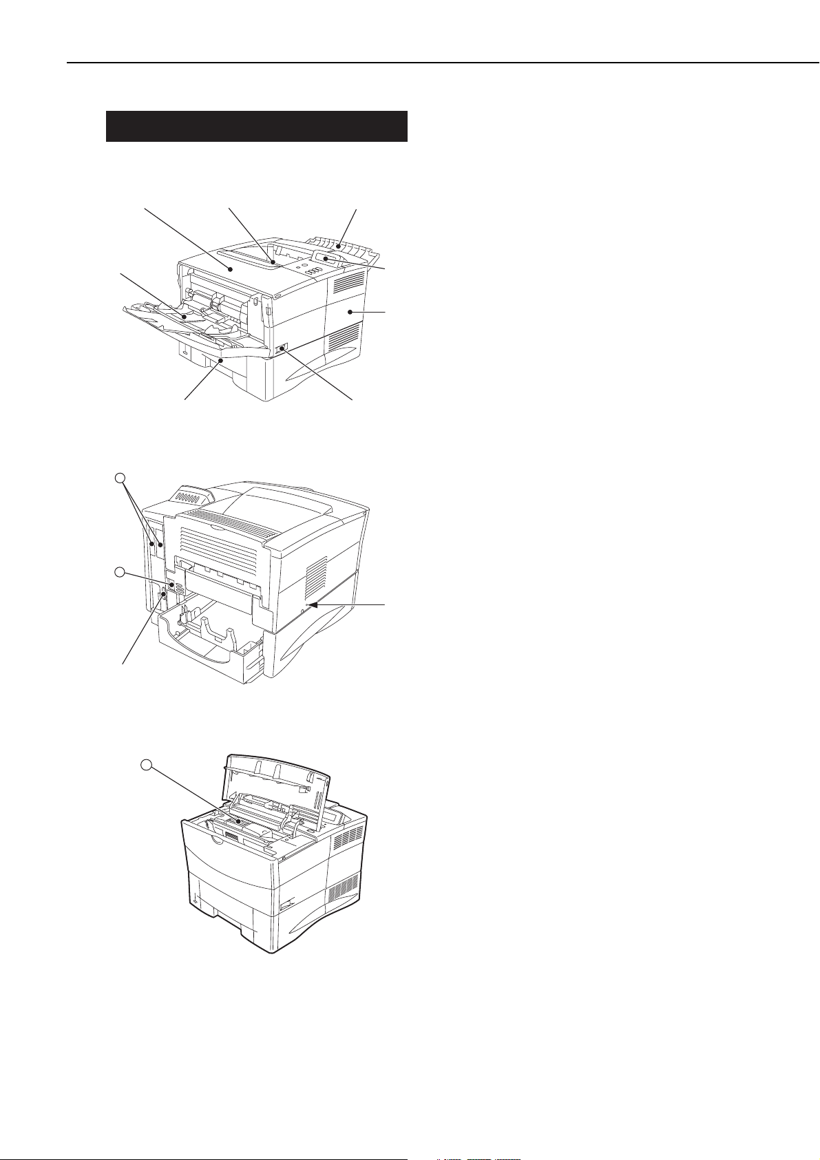
IV. PARTS OF THE PRINTER
A. External Views
1. Printer
Figure 1-4-1
Figure 1-4-2
Figure 1-4-3
1: Face-down tray
2: Face-up tray
3: Operation panel
4: Right rear cover
5: Power switch
6: Cassette
7: Multi-purpose tray
8: Top cover
9: Test print switch
10: Parallel interface connector
11: Power receptacle
12: Expansion I/O slots
13: EP-52 cartridge
1 - 7
CHAPTER 1
➇
➆
➀
➁
➄➅
➂
➃
12
11
➈
➉
13
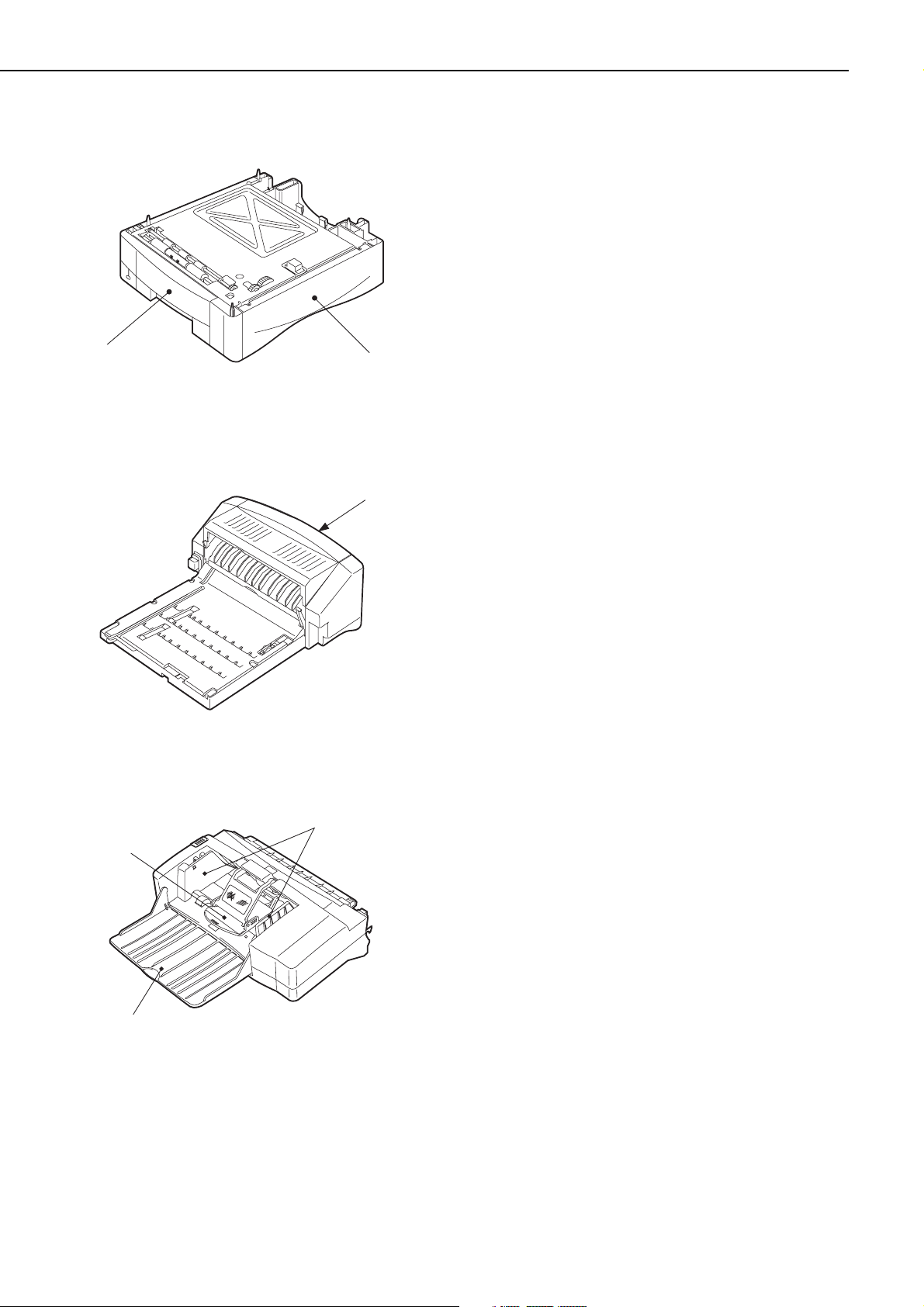
2. Paper feeder
Figure 1-4-4
3. Duplexing unit
Figure 1-4-5
4. Envelope feeder
Figure 1-4-6
1: Paper feeder
2: 500-sheet cassette
1: Duplexing unit jam release cover
1: Envelope guide
2: Extension tray
3: Weight
1 - 8
CHAPTER 1
➁
➀
➀
➂
➁
➀
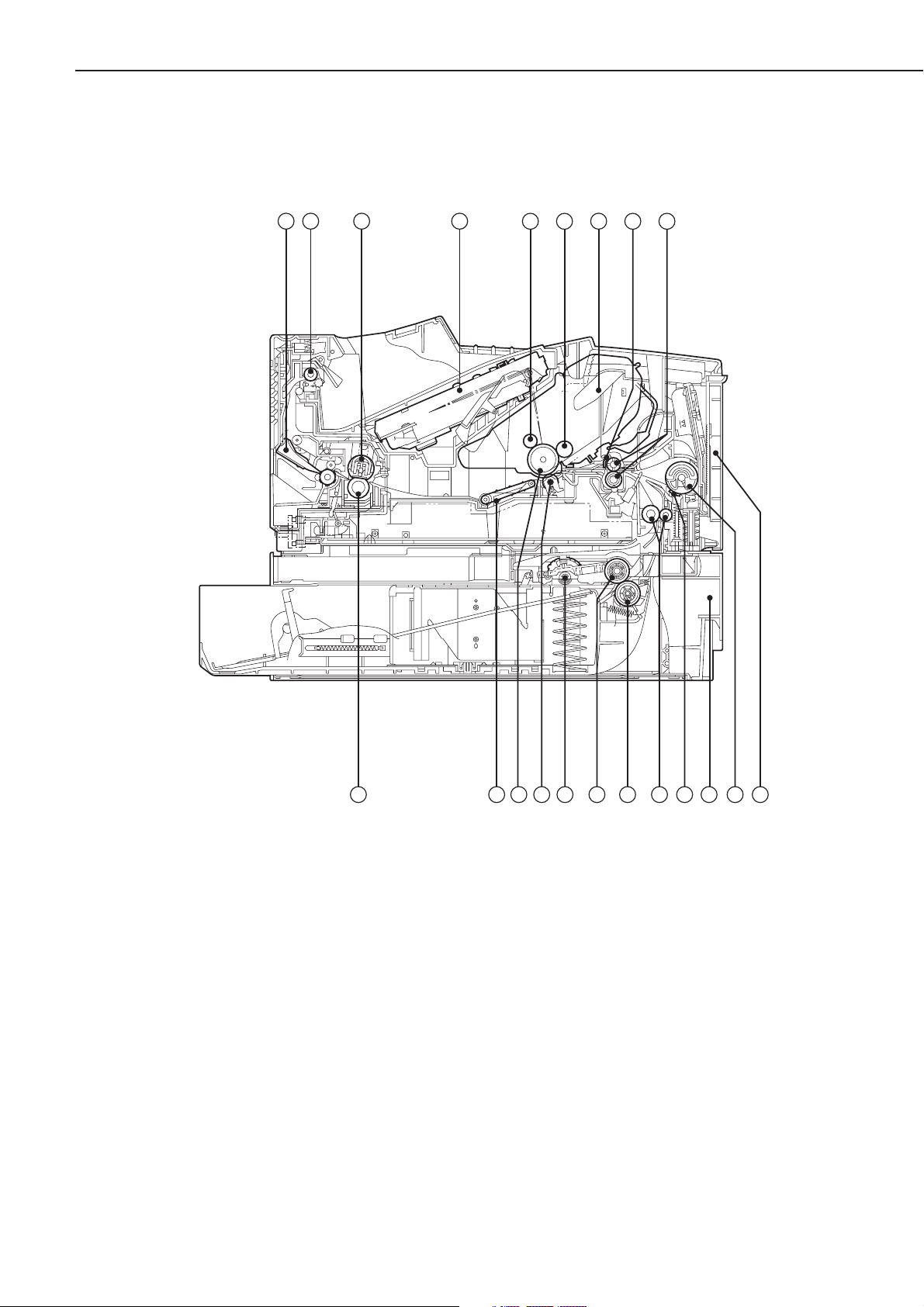
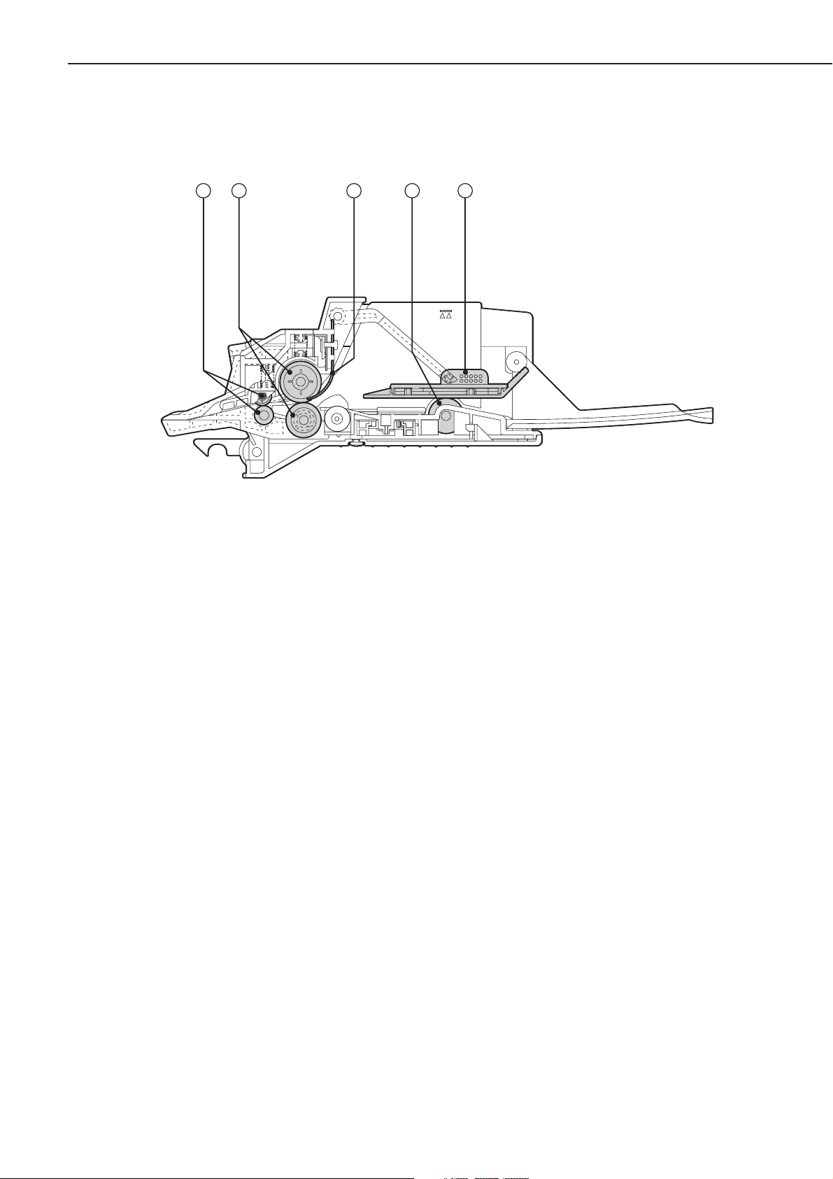
B. Cross-sectional Views
1. Printer
Figure 1-4-7
1 - 9
CHAPTER 1
1: Face-up deflector
2: Face-down delivery roller
3: Fixing film unit
4: Laser/scanner unit
5: Primary charging roller
6: Developing cylinder
7: EP-52 cartridge
8: Registration arm
9: Pre-transfer rollers
10: Multi-purpose tray
11: Multi-purpose tray pick-up roller
12: Cassette
13: Separation pad
14: Feed rollers
15: Cassette separation roller
16: Cassette feed roller
17: Cassette pick-up rollers
18: Transfer charging roller
19: Photosensitive drum
20: Feed belt
21: Pressure roller
1 2 3
4
5 6
7
8 9
21 20
14
1517 161819
13 11 1012
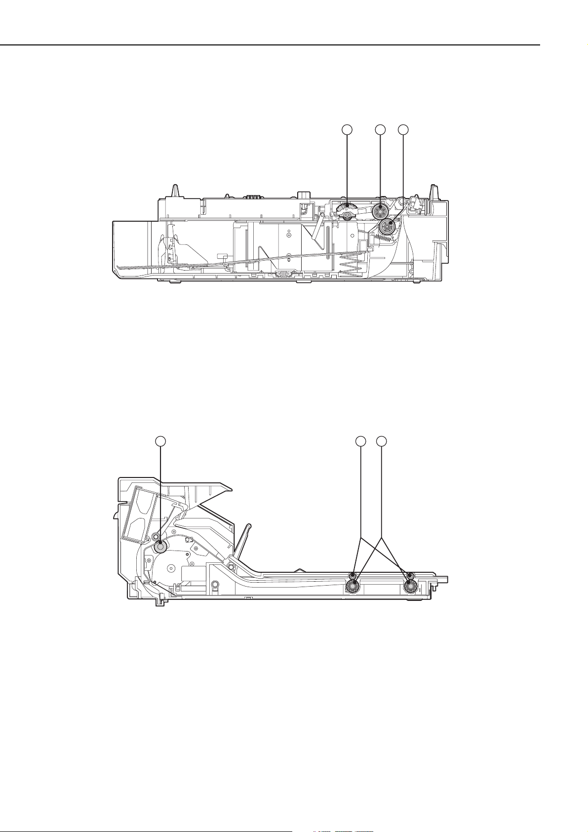
2. Paper feeder
Figure 1-4-8
1: Pick-up roller
2: Feed roller
3: Separation roller
3. Duplexing unit
Figure 1-4-9
1: Reversing roller
2: Oblique rollers
3: Duplexing unit pick-up rollers
1 - 10
CHAPTER 1
1 2 3
21 3
4. Envelope feeder
Figure 1-4-10
1: Feed rollers
2: Separation rollers
3: Separation guide
4: Pick-up rollers
5: Weight
1 - 11
CHAPTER 1
1 2 3 4 5

V. INSTALLATION
A. Outline
This printer is packaged and shipped from the factory after careful adjustments and rigorous
inspections.
When installing the printer, it is important to demonstrate its performance in the same way
as when it passed the factory inspection.
The service engineer must sufficiently understand the performance of the printer, install it
correctly in a location with an appropriate environment, and conduct sufficient checks of the
unit.
B. Location Selection
Before taking the printer to the customer’s premises, you should confirm the following installation conditions.
1. Power supply
Use the following power supplies:
• Line voltage (AC): -10%, +6% rated voltage
• Power frequency: 50/60 Hz±2 Hz
2. Operating environment
Install in a location that meets the following conditions:
• Level, flat surface
• Temperature, humidity within the following ranges:
Surrounding temperature: 7.5 ~ 32.5°C
Surrounding humidity: 5 ~ 90%RH (relative humidity)
• Cool, well-ventilated space
Do not install in the following locations:
• Exposed to direct sunlight
If you cannot avoid such a location, hang heavy curtains, etc. to shut out the direct sunlight.
• Near magnets and devices that emit a magnetic field
• Areas with vibration
• Dusty places
• Near fire or water
3. Installation space
Install the printer at a suitable distance from the walls, leaving enough room to operate it (see
Figure 1-5-1).
When installing the printer on a desk, be sure that it is large enough to accommodate the
printer’s feet (rubber pads) and strong enough to stand its weight.
1 - 12
CHAPTER 1
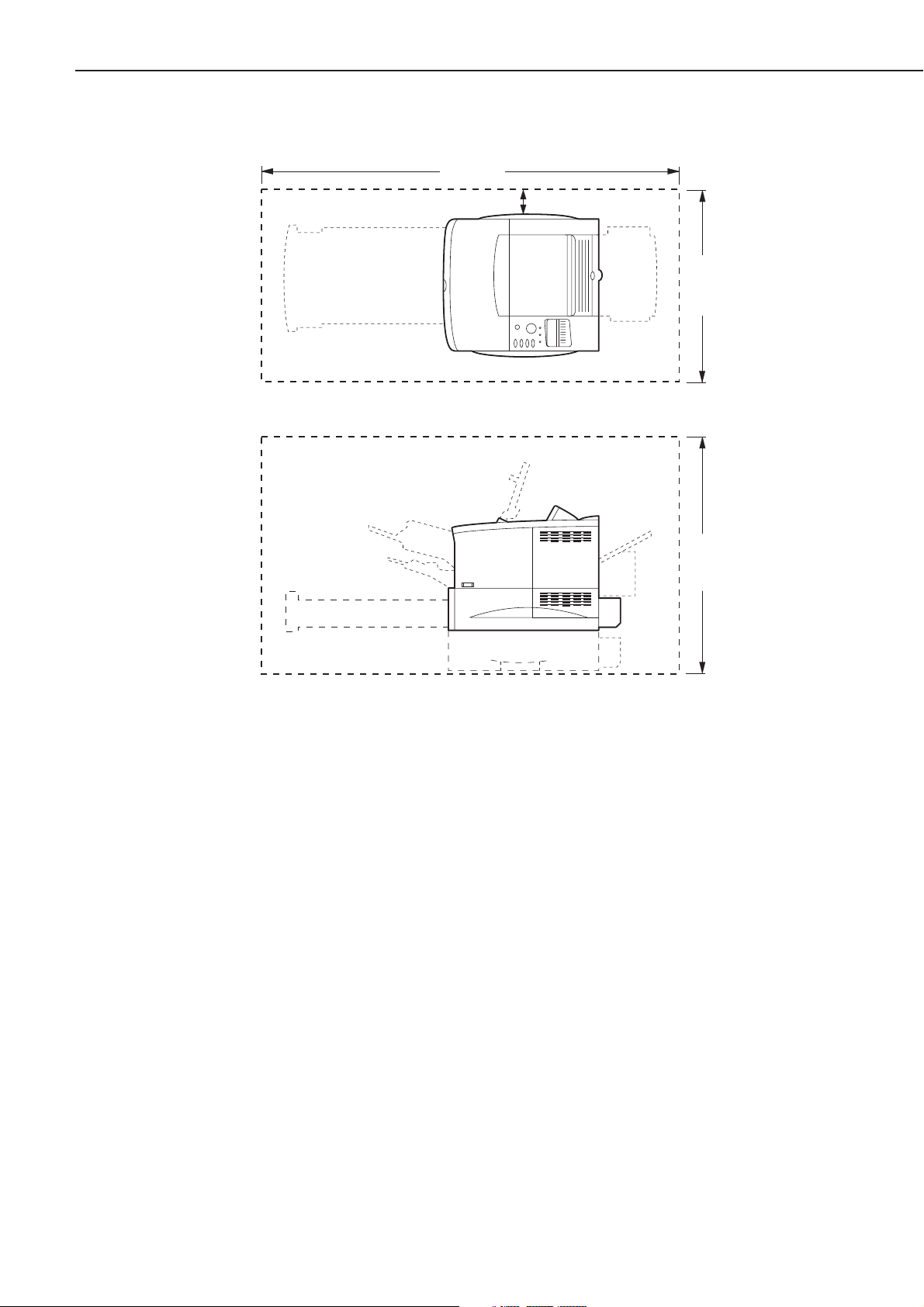
Figure 1-5-1
1 - 13
CHAPTER 1
1220mm
100mm
600mm
630mm

C. Unpacking and Installation
Condensation appear on metal surfaces in the printer when brought from a cold area into a
warm area. Also, since the condensation can cause various troubles including print defects, in
such a case, leave it in the carton at room temperature for at least an hour so that it is acclimatized to room temperature.
When installing the options, be sure that the printer is powered OFF.
1. Printer
1) Open the printer packaging.
2) Take out the accessories. Confirm that the power cord, cartridge, CD-ROM, and manuals
are included.
3) Take the plastic bag off the printer and peel the tape off each part. Confirm that none of the
covers were scratched or deformed during shipment.
4) Open the top cover and remove the tape and packing materials from inside the printer.
5) Remove the tape and spacer from the face-down tray.
6) Take out the cassette from the printer, and remove the packing materials from the cassette.
2. Cartridge
1) Open the bag holding the cartridge and take out the cartridge.
2) Hold the cartridge as shown in figure 1-5-2 and slowly rock it to right and left 5 to 6 times
so that the toner is evenly distributed.
3) Place the cartridge on a flat surface. While holding down on the top of the cartridge with one
hand, grasp the tab with the other hand and gently pull out the sealing tape.
4) Open the top cover of the printer and load the cartridge in the printer. Make sure to insert
the cartridge until it firmly contacts with the back of the slot.
3. Paper feeder
1) Open the paper feeder packaging.
2) Take out the paper feeder with the front and rear pads from the package.
3) Take the plastic bag off the paper feeder and peel the tape off each part. Confirm that none
of the covers were scratched or deformed during shipment.
4) Remove the packing materials from the paper feeder.
5) Place the paper feeder on a flat surface.
6) Lift the printer, and align the positioning pins of the paper feeder with the positioning holes
of the printer.
4. Envelope feeder
1) Open the envelope feeder packaging.
2) Take off the plastic bag and peel the tape off. Confirm that none of the covers were scratched
or deformed during shipment.
3) Remove the packing materials from the envelope feeder.
4) Open the multi-purpose tray of the printer, remove the envelope entrance cover, and open
the envelope feeder gear cover.
5) Holding the envelope feeder with both hands, install it into the printer.
5. Duplexing unit
1) Open the duplexing unit packaging.
2) Take off the plastic bag and peel the tape off. Confirm that none of the covers were scratched
or deformed during shipment.
3) Remove the packing materials from the duplexing unit.
4) Remove the 2 duplexing unit slot covers from the printer.
5) Holding the duplexing unit with both hands, install in into the printer.
1 - 14
CHAPTER 1

6. Operation confirmation
1) Load paper in the cassette.
2) Plug the power cord into the printer and outlet, and turn the power switch ON. Be sure to
use the enclosed power cord.
3) After the printer enters the STANDBY mode, press the test print switch to make a test print.
Check if the density of the output image is correct.
4) Keep clean around the printer and ensure that it is ready for use at anytime.
1 - 15
CHAPTER 1
D. Storing, Handling the EP-52 Cartridge
Whether the cartridge is still sealed in its box or installed in the printer, the effect of the natural environment will change it over time regardless of the number of prints. As the progression
of this natural change depends on the storage or installation environment, take sufficient care
in storing and handling the cartridges.
a. Before unsealing the box
When the cartridge is stored in a warehouse, workshop, etc., be sure to keep it within the ranges
shown in Table 1-5-1. Note the following points:
1) Avoid locations in direct sunlight.
2) Do not leave in areas exposed to strong vibration.
3) Do not bump or drop.
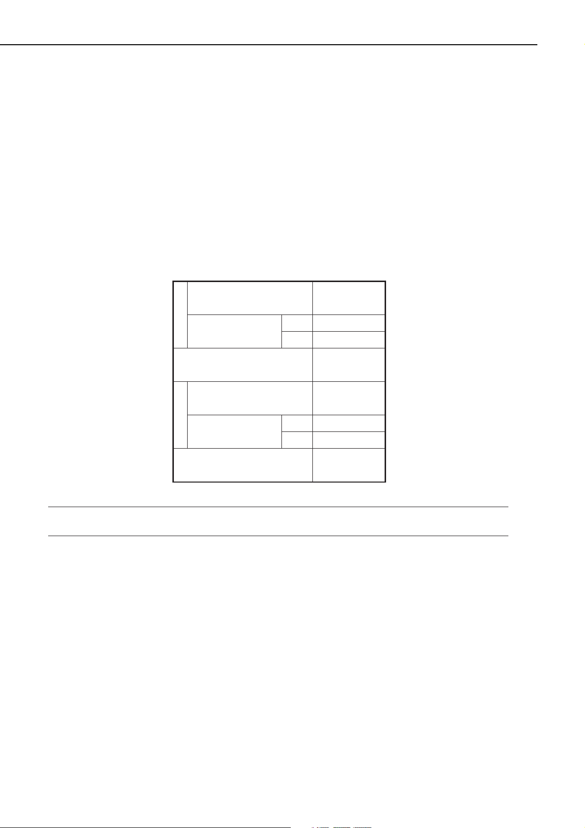
Table 1-5-1 Environmental conditions
Note: Total storage time is the valid time span following the manufacture date displayed on
the cartridge box.
b. Storing unsealed parts
As an organic photoconductor (OPC) is used in the photosensitive drum, it will deteriorate if
exposed to strong light. As there is also toner in the cartridge, be sure to explain to the customer the need to be careful in handling and storing unsealed cartridges.
1. Storage environment
1) Be sure to store in the protective bag.
2) Avoid locations exposed to direct sunlight, near windows, etc. Do not leave the cartridge in
cars for any extended period of time as heat can damage it.
3) Avoid high, low, and changeable temperature/humidity locations.
4) Avoid sites with corrosive gases (pesticides) or salt in the air.
5) Store the cartridge within a range of 0 to 35°C.
6) Do not place the cartridge near CRT displays, disk drives, or floppy disks.
7) Store the cartridges out of reach of children.
1 - 16
CHAPTER 1
Normal (total storage time ×
9/10)
Severe (total storage
time × 1/10)
Temperature
Temperature change (within
3 minutes or so)
Normal (total storage time ×
9/10)
humidity
Severe (total storage
time 1/10)
Relative
Air pressure
High
Low –20 to 0°C
High
Low
0to35°C
35 to 40°C
40°C→15°C
–20°C→25°C
35 to 85% RH
85 to 95% RH
10 to 35% RH
345 to 1013 hPa
(460 to 760 mmHg)
2. Effective life
Cartridges are effective for 2.5 years following the date of manufacture, which is displayed in an
abbreviated form on the cartridge. The cartridge life span is also displayed (month and year) on
the cartridge box as 2.5 years from the date of manufacture. Cartridges should be used within
their life spans, as image quality will deteriorate after the expiry date.
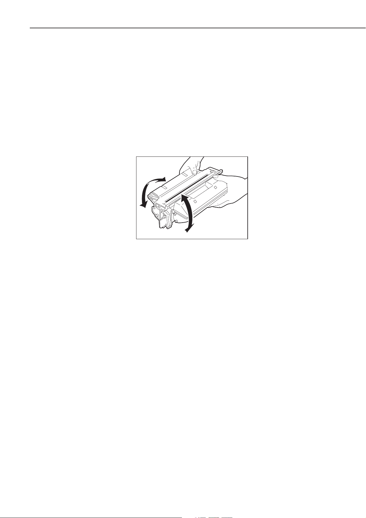
c. Handling
1) When loading a new cartridge into the printer, or when blank spots appear on output images
due to uneven distribution of the toner during use, hold the cartridge at each end as shown
in the figure below. Slowly rock it 5 to 6 times at a 45-degree angle to evenly distribute the
toner, and reload it into the printer. Do not shake the cartridge in any other ways, as toner
may leak from the developing cylinder or the cleaning unit.
Figure 1-5-2
After loading the cartridge in the printer, print 3 to 5 sheets of test patterns and check for
toner leakage to prevent output image from dirt.
2) Remove the cartridge from the printer before transporting it. During transportation, the cartridge must be kept in the protective bag or thick cloth to prevent direct exposure to light.
3) Avoid placing the cartridge near CRT displays, disk drives or floppy disks, as the magnetism
generated by the cartridge may destroy the data.
4) As the photosensitive drum is sensitive to strong light, do not expose the cartridge to direct
sunlight or strong light. If it is exposed to strong light, blank spots or black lines may appear
on images. In such cases, stop the printer for a while. However, these problems may still
remain if the drum has been exposed to strong light for an extended period of time.
5) Do not open the photosensitive drum protective shutter by hand nor touch the drum surface. Do not clean the drum.
6) Do not stand the cartridge nor upside down. Always place it so that the label side faces
upward.
7) Do not disassemble the cartridge.
1 - 17
CHAPTER 1

Figure 1-5-3
1 - 18
CHAPTER 1
VI. MAINTENANCE AND SERVICING BY THE CUSTOMER
Table 1-6-1 shows the maintenance the customer should conduct to ensure optimum machine
performance at all times.
Table 1-6-1
1 - 19
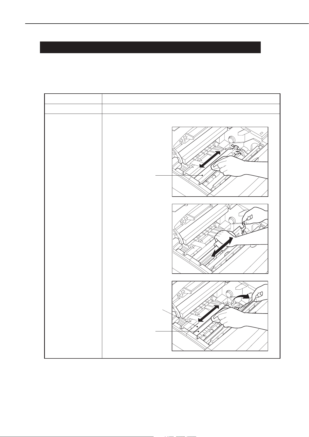
CHAPTER 1
Item
Cartridge
Transfer guide
Customer maintenance
Rock the cartridgeor replace it, if necessary.
Clean the transfer guide when replacing the cartridge.
Upper transfer guide
Transfer charging roller
Lower transfer guide
VII. OPERATION
A. The Operation Panel
The operation panel is used to perform basic printer operations, make printer configuration
changes that software applications cannot control, identify available typefaces, and check the
status of the printer.
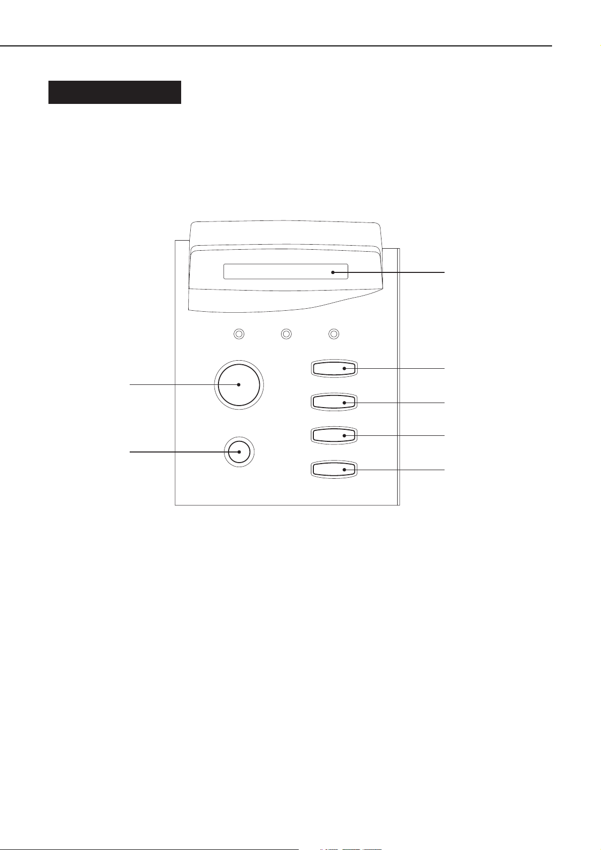
The operation panel consists of the status indication display, three indicator lights, and six
menu and operation keys.
Figure 1-7-1
• Status indication display (2-line, 16-segment LCD): 1
Indicates the printer status and menu setting, and displays messages.
• On Line indicator: 2
ON:
The printer is on-line.
Blinking:
The printer is processing or printing.
OFF:
The printer is off-line.
• Job indicator: 3
ON:
A page buffer has been composed and is currently stored in printer memory.
Blinking:
1 - 20
CHAPTER 1
➀
On Line
Job
Alarm
➁➂➃
Go
➉
Shift
➈
Menu
Item
V alue
Enter/Cancel
➄
➅
➆
➇
 Loading...