


PUB. DIE-0356-000B
HD Camcorder
Instruction Manual
PAL
Important Usage Instructions
WARNING:
TO REDUCE THE RISK OF ELECTRIC SHOCK, DO NOT REMOVE COVER (OR BACK). NO USER SERVICEABLE PARTS INSIDE.
REFER SERVICING TO QUALIFIED SERVICE PERSONNEL.
WARNING:
TO REDUCE THE RISK OF FIRE OR ELECTRIC SHOCK, DO NOT EXPOSE THIS PRODUCT TO RAIN OR MOISTURE.
COPYRIGHT WARNING:
Unauthorized recording of copyrighted materials may infringe on the rights of copyright owners and be contrary to copyright laws.
CAUTION:
TO REDUCE THE RISK OF ELECTRIC SHOCK AND TO REDUCE ANNOYING INTERFERENCE, USE THE RECOMMENDED ACCESSORIES ONLY.
CAUTION:
DISCONNECT THE MAINS PLUG FROM THE SUPPLY SOCKET WHEN NOT IN USE.
To reduce the risk of electric shock, do not expose this product to dripping or splashing.
For Users in the UK
When replacing the fuse only a correctly rated approved type should be used and be sure to re-fit the fuse cover.
The Mains plug is used as the disconnect device. The Mains plug shall remain readily operable to disconnect the plug in case of an accident.
CAUTION:
•Danger of explosion if the wrong type of batteries are attached. Use only the same type of batteries.
•Do not expose batteries or product to excessive heat such as the inside of a car under direct sunlight, fire, etc.
While using the compact power adapter, do not wrap it or cover it with a piece of cloth, and do not place it in confined narrow spaces. Heat may build up, the plastic case may deform and it could result in electric shock or fire.
CA-930 identification plate is located on the bottom.
2

European Union (and EEA) only.
These symbols indicate that this product is not to be disposed of with your household waste, according to the WEEE Directive (2002/96/EC), the Battery Directive (2006/66/EC) and/or your national laws implementing those Directives.
 This product should be handed over to a designated collection point, e.g., on an authorized one-for-one basis when you buy a new similar product or to an authorized collection site for recycling waste electrical and electronic equipment (EEE) and batteries and accumulators. Improper handling of this type of waste could have a possible impact on the environment and human health due to potentially hazardous substances that are generally associated with EEE. Your cooperation in the correct disposal of this product will contribute to the effective usage of natural resources.
For more information about the recycling of this product, please contact your local city office, waste authority, approved scheme or your household waste disposal service or visit www.canon-europe.com/environment. (EEA: Norway, Iceland and Liechtenstein)
Trademark Acknowledgements
•SD and SDHC logos are trademarks of SD-3C, LLC.
•CompactFlash is a trademark of SanDisk Corporation.
•Microsoft and Windows are trademarks or registered trademarks of Microsoft Corporation in the United States and/or other countries.
•Apple, Macintosh, Mac OS, Final Cut Pro are trademarks of Apple Inc., registered in the U.S. and other countries.
•Avid and Media Composer are trademarks or registered trademarks of Avid Technology, Inc. or its subsidiaries in the United States and/or other countries.
•HDMI, the HDMI logo and High-Definition Multimedia Interface are trademarks or registered trademarks of HDMI Licensing LLC in the United States and other countries.
•Other names and products not mentioned above may be trademarks or registered trademarks of their respective companies.
•This device incorporates exFAT technology licensed from Microsoft.
•ANY USE OF THIS PRODUCT OTHER THAN CONSUMER PERSONAL USE IN ANY MANNER THAT COMPLIES WITH THE MPEG-2 STANDARD FOR ENCODING VIDEO INFORMATION FOR PACKAGED MEDIA IS EXPRESSLY PROHIBITED WITHOUT A LICENSE UNDER APPLICABLE PATENTS IN THE MPEG-2 PATENT PORTFOLIO, WHICH LICENSE IS AVAILABLE FROM MPEG LA, L.L.C., 250 STEELE STREET, SUITE 300, DENVER, COLORADO 80206.
3
Highlights of the XF305/XF300
The Canon XF305/XF300 HD Camcorder has been designed to fulfill the needs demanded by industry professionals. The following are just some of the many features that will help turn your creative vision into reality.
HD Recording
3CMOS system and DIGIC DV III image processor
The camcorder is equipped with three 1/3-type CMOS sensors that each capture video at an effective pixel count of approximately 2.07 megapixels (1920x1080). Combined with the DIGIC DV III image processor and newly developed 18x zoom lens (29.3 mm, F1.6), the camcorder offers a center resolution of 1,000 TV lines. Furthermore, the camcorder produces spectacular video with true-to- life color reproduction while reducing noise and “rolling shutter” artifacts thanks to a twofold improvement (when the frame rate is 50i) over previous models in scanning speed.
Superb HD video
The camcorder uses the MPEG-2 Long GOP codec. When you record using the 50 Mbps bit rate (with 4:2:2 color sampling), the quality of your recordings will rival that of broadcast video. Your recordings are saved as Material eXchange Format (MXF) files, which are compatible with major non-linear editing (NLE) software.
You can configure the video recording signal to suit your needs. By combining the bit rate/resolution setting with the frame rate setting, you can produce video from 1440x1080/25P at 25 Mbps to 1280x720/50P at 35 Mbps to 1920x1080/50i at 50 Mbps. You can select from a total of 10 different combinations!
Operability
Focus and zoom
Enhancements were made to the focus and zoom systems. The newly added full manual focus mode (052) sets physical stops on the focus ring and also displays a distance indicator on the ring itself. With the physical stops on the zoom ring (074), you can easily go from full wide angle to full telephoto by turning the zoom ring about 90°.
Overall design
The various buttons, switches and other controls were redesigned after extensive research and interviews with industry professionals. Buttons and switches were repositioned for easier use and access and the ergonomic design of the grip was also refined for better balance. In addition, you can frame your shots more easily with the improved viewfinder and larger LCD screen, which both now have 100% coverage.
Recording media
The camcorder records video and audio to CompactFlash (CF) cards. You can even make lengthy recordings without worry because the camcorder features two CF card slots. When one CF card becomes full, the recording will automatically continue on the other one without interruption.
Supplied Canon XF Utility software
Managing your recordings is as simple as using the supplied Canon XF Utility software. You can transfer your recordings to your computer, where you can view and manage them. Using the supplied plugins, you can then use the recordings with major NLE software*.
*Refer to Saving Clips to a Computer (0146) for details on compatible software.
Versatile Artistic Expression
Special recording modes
The special recording modes (0101) give you more creative control over your recordings. You can create a slow motion or fast motion effect in your recordings, record a certain number of frames at a set interval (ideal for subjects with little movement) or record a certain number of frames every time you press a button (ideal for stop motion animation).
Custom picture settings
With custom picture settings (0109), you can enjoy unparalleled image control to deliver the “look” you want by adjusting parameters, such as gamma and sharpness. The custom picture settings can be recorded onto an SD card, which allows multiple XF305/XF300 camcorders to use the same settings, or embedded in the recording itself.
4
Advanced Professional Features
Pro-level connectivity (bonly)
An industry-standard HD/SD SDI terminal (0142) for uncompressed HD signal output, embedded audio and SMPTE time code (LTC) give the camcorder the functionality of professional broadcast cameras. Genlock synchronization (086) and the TIME CODE terminal (086) allow the camcorder to be part of any multi-camera shooting setup.
Customization
The camcorder features several customization options. You can assign often-used functions to assignable buttons (0107) so that you can call up those functions with the press of a single button. Custom functions (0120) and custom onscreen displays (0121) give you even more freedom to control many aspects of the camcorder’s operation. Save custom picture and menu settings to an SD card so that you can transfer your setting preferences to other XF305/XF300 camcorders in order to use them in the same way.
Other Functions
Audio
Sound is recorded as 2-channel linear PCM audio (16-bit/48 kHz). You can use the built-in microphone or the two XLR audio input terminals (with phantom power supply) when recording.
Video scopes
Check the brightness of the image using the waveform monitor (096), the color of the image using the vectorscope (097), or the focus using the edge monitor (097).
Added and improved functionality
Other functions include improved image stabilization (059), the option to add metadata to recordings (094), and the Intelligent System-compatible battery pack (0191).
5
Table of Contents
1. Introduction 9
About this Manual 9
Conventions Used in this Manual 9
Supplied Accessories 11
Names of Parts 12
2. Preparations |
21 |
|
|
|
|
|
|
|
Preparing the Power Supply |
21 |
|
|
|
|
|||
Using a Battery Pack |
21 |
|
|
|
|
|
|
|
Turning the Camcorder On and Off |
25 |
|
||||||
Date, Time and Language Settings |
26 |
|
||||||
Setting the Date and Time |
26 |
|
|
|
|
|||
Changing the Time Zone |
26 |
|
|
|
|
|||
Displaying the Date and Time while Recording |
27 |
|||||||
Changing the Language |
27 |
|
|
|
|
|||
Using the Menus |
28 |
|
|
|
|
|
|
|
Selecting an Option from the Menu |
28 |
|
||||||
Preparing the Camcorder |
30 |
|
|
|
|
|||
Attaching the Lens Hood |
30 |
|
|
|
|
|||
Attaching and Detaching the Eye Cup |
30 |
|
||||||
Dioptric Adjustment |
31 |
|
|
|
|
|
|
|
Using the LCD Panel |
32 |
|
|
|
|
|
|
|
Using the Viewfinder and LCD Screen |
|
|
||||||
Simultaneously |
32 |
|
|
|
|
|
|
|
Adjusting the Viewfinder/LCD Screen |
33 |
|
||||||
Setting the Screen to Black & White |
33 |
|
||||||
Adjusting the Grip Belt 34 |
|
|
|
|
|
|||
Attaching a Shoulder Strap |
34 |
|
|
|
|
|||
Removing and Attaching the Terminal Covers |
35 |
|||||||
Using the Wireless Controller 35 |
|
|
|
|
||||
Using a Tripod |
36 |
|
|
|
|
|
|
|
Preparing Recording Media |
37 |
|
|
|
|
|||
Inserting a CF Card |
37 |
|
|
|
|
|
|
|
Checking the Status of the CF Card Slots 38 |
|
|||||||
Removing a CF card |
38 |
|
|
|
|
|
|
|
Inserting and Removing an SD Card |
|
39 |
|
|||||
Initializing the Recording Media 39 |
|
|
|
|||||
Switching Between the CF Card Slots |
40 |
|
||||||
Checking the Available Recording Time 41 |
|
|||||||
Recovering Data on the CF Card |
41 |
|
|
|||||
3. Recording 43
Recording Video 43
Preparing to Record 43
Recording 44
Onscreen Displays 46
Side Panel Displays 48
Power Save Mode 50
Video Configuration: Bit Rate, Resolution and
Frame Rate 51
Adjusting the Focus 52
Full Manual Focus Mode 52
Manual Focus Mode 53
Using the Focus Assistance Functions 54
Autofocus Mode 56
Push AF 57
Detecting and Focusing On Faces 57
Focus Limit and Macro Shooting 58
Image Stabilizer 59
Gain 60
Automatic Gain Control (AGC) 60
Manual Gain Control 61
Shutter Speed 63
Changing the Shutter Speed Mode 64
Flicker Reduction 65
Adjusting the Aperture 66
Automatic Aperture Control 66
Manual Aperture Control 66
Temporary Manual Aperture Control Override
(PUSH AUTO IRIS) 67
Adjusting the AE Level 68
Setting the Light Metering Mode 68
Using the ND Filter 69
White Balance 70
Auto White Balance 70
Preset White Balance 71
Setting the Color Temperature 72
Custom White Balance 72
Zooming 74
Selecting the Zoom Controls 74 Using the Zoom Ring 74
Using the Zoom Rockers, Wireless Controller or Optional Remote Control 75
6
Onscreen Markers and Zebra Patterns |
78 |
|
Displaying Onscreen Markers |
78 |
|
Displaying Zebra Patterns 79 |
|
|
Setting the Time Code 81 |
|
|
Selecting the Running Mode |
81 |
|
Putting the Time Code Display on Hold |
83 |
|
Setting the User Bit 84 |
|
|
bSynchronizing with an External Device 85
Connecting an External Device 85 Using a Reference Video Signal
(Genlock Synchronization) 86 Using a Time Code Signal 86 Time Code Signal Output 87
Recording Audio 88
Using the Built-in Microphone 88
Using an External Microphone or Line Input 89 Adjusting the Audio Level 92
Monitoring the Audio with Headphones 93
Using Metadata 94
Setting a User Memo 94
Colors Bars/Audio Reference Signal 95
Recording Color Bars 95
Recording an Audio Reference Signal 95
Video Scopes 96
Displaying a Video Scope 96
Configuring the Waveform Monitor 96
Configuring the Vectorscope 97
Configuring the Edge Monitor 97
Adding Shot Marks while Recording 99 Reviewing a Recording 100
Special Recording Modes 101
Interval Recording Mode 101
Frame Recording Mode 103
Slow & Fast Motion Mode 104 Pre-recording Mode 106
4. Customization 107
Assignable Buttons 107
Changing the Assigned Function 107
Using an Assignable Button 108
Custom Picture Settings 109 |
|
Selecting Custom Picture Files |
109 |
Editing a Custom Picture File’s Settings 110 |
|
Renaming Custom Picture Files |
110 |
Protecting Custom Picture Files |
111 |
Transferring Custom Picture Files 111
Embedding Custom Picture Settings in a
Recording 112
Available Custom Picture Settings 113
Customizing Functions and Onscreen
Displays 120
Customizing Functions 120
Customizing Onscreen Displays 121
Saving and Loading Camera Settings 122
Saving Camera Settings to an SD Card 122 Loading Camera Settings from an SD Card 122
5. Playback 123
Playback 123
Clip Index Screen 123
Playing Back Clips 125
Onscreen Displays 125
Playback Controls 127 Adjusting the Volume 128
Adding Shot Marks during Playback 128
Clip Operations 129
Using the Clip Menu 130 Displaying Clip Information 130 Adding eMarks or ZMarks 131 Deleting eMarks or ZMarks 132 Copying Clips 132
Deleting Clips 134
Deleting the User Memo 134
Copying a Custom Picture File Embedded in a Clip 135
Displaying an Index Screen of Shot Marks 135 Displaying a Frame Index Screen of a Single
Clip 136
Adding or Deleting Shot Marks from an Index Screen 137
Changing a Clip’s Thumbnail 138
7
6. External Connections 139
Video Output Configuration 139
Video Output Configuration by Terminal 139
SD Output 140
Connecting to an External Monitor 141
Connection Diagram 141
bUsing the HD/SD SDI Terminal 142 Using the HDMI OUT Terminal 142
Using the HD/SD COMPONENT OUT Terminal 142
Using the AV or VIDEO 2 Terminal 143 Superimposing Onscreen Displays to Appear on an
External Monitor 143 |
|
|
Audio Output 144 |
|
|
bEmbedded Audio |
144 |
|
Synchronizing the Video with the Audio being |
||
Monitored |
144 |
|
Selecting the Audio Channel |
145 |
|
Selecting the Output Level of the AV Terminal 145 |
||
Saving Clips to a Computer |
146 |
|
System Requirements 146 |
|
|
Installing and Uninstalling Canon XF Utility |
||
(Windows) |
147 |
|
Installing and Uninstalling Canon XF Utility |
||
(Mac OS) |
150 |
|
Viewing the Software Instruction Manuals 153
7. Photos 155
Taking Photos 155 |
|
|
Taking Photos in CAMERA Mode |
155 |
|
Capturing Photos in MEDIA Mode |
156 |
|
Photo Playback |
157 |
|
Displaying the [Photos] Index Screen 157 |
||
Viewing Photos |
157 |
|
Photo Operations |
158 |
|
Using the Photo Menu 158 |
|
|
Deleting Photos |
158 |
|
Protecting Photos 159
Copying Custom Picture Files 160
Photo Numbering 161
8. Additional Information 163
Menu Options 163
Displaying the Status Screens 172
Troubleshooting 178
List of Messages 181
Handling Precautions 185
Maintenance/Others 188
Optional Accessories 190
Specifications 194
Index 198
8

Introduction
About this Manual
Introduction |
1 |
|
|
Thank you for purchasing the Canon XF305/XF300. Please read this manual carefully before you use the camcorder and retain it for future reference. Should the camcorder fail to operate correctly, refer to
Troubleshooting (0178).
Conventions Used in this Manual
• IMPORTANT: Precautions related to the camcorder’s operation.
• NOTES: Additional topics that complement the basic operating procedures.
•0: Reference page number.
•b: Text that applies only to the model shown in the icon.
•The following terms are used in this manual.
“Screen” refers to the LCD screen and the viewfinder screen. “CF card” refers to a CompactFlash (CF) card.
“SD card” refers to an SD or SDHC memory card. “Recording media” refers to CF cards and SD cards.
•Photographs in the manual are simulated pictures taken with a still camera. Some screenshots have been altered to make them easier to read.
•Illustrations in the manual show the b.
9

1 |
Introduction |
About this Manual |
|
|
|
When a function requires the use of the menu, the quick reference shows the submenus and, when applicable, the default setting for the menu item. The example illustration indicates that you can find the function by selecting the [lCamera Setup] menu and then the [Image Stabilizer] menu item.
Operating modes
 indicates that a function is available in the operating mode indicated and
  indicates that the function is not available. For a detailed explanation, refer to Turning the Camcorder On and Off (025).
3Recording Image Stabilizer
Image Stabilizer
[lCamera Setup]
[Image Stabilizer]
[Standard]
Use the image stabilizer to compensate for camcorder shake in order to achieve steadier shots. There are 3 methods of image stabilization; select the method that best suits your needs.
Operating modes: 

1 Open the [Image Stabilizer] submenu.
[lCamera Setup]  [Image Stabilizer]
2 Select the desired option and then press SET.
• The icon of the selected mode appears on the bottom of the screen.
Options
[Powered] Q: Powered IS is most effective when you are stationary and zooming in on far subjects using high zoom ratios (the more you approach the telephoto end). This mode is not suitable for tilting and panning shots.
[Dynamic] P: Dynamic IS compensates for a higher degree of camcorder shake, such as when shooting while walking, and is more effective as the zoom approaches full wide angle.
[Standard] O: Standard IS compensates for a lower degree of camcorder shake, such as when shooting while remaining stationary, and is suitable for shooting natural-looking scenes.
[Off]: Use this setting when the camcorder is mounted on a tripod.
 NOTES
NOTES
•By default, assignable button 1 is set to [Standard] but you can also set it for another assignable button instead. You can press the button to activate standard IS.
•If you set an assignable button to [Dynamic IS] or [Powered IS]
(0111), you can press the button to turn the assigned mode on or off.
•If the degree of camcorder shake is too high, the image stabilizer may not be able to fully compensate.
•When you are using [Dynamic] mode the edges of the picture may be
When a procedure requires selecting an option, the available options are listed within or after the procedure. Brackets [ ] are used to refer to menu options as they are displayed on screen.
The arrow is used to abbreviate menu selections. For a detailed explanation on how to use the menus, refer to Using the Menus (028). For a concise summary of all available menu options and settings, refer to the appendix Menu Options (0163).
10
Supplied Accessories
Introduction |
1 |
|
|
The following accessories are supplied with the camcorder.
|
|
|
|
|
CA-930 Compact Power Adapter |
|
BP-955 Battery Pack |
|
DC-930 DC Cable |
(incl. power cord) |
|
(incl. terminal cover) |
|
|
|
|
|
|
|
|
|
|
|
|
DTC-1500 Component |
|
Lens Hood |
|
Eye Cup |
Video Cable |
|
|
|
|
|
|
|
|
|
|
|
|
|
|
Lens Cap |
WL-D6000 Wireless Controller |
SS-1200 Shoulder Strap |
|
(incl. CR2025 Lithium Battery) |
|
|
|
|
|
|
|
Canon XF Utilities Disc*
*The Canon XF Utilities Disc includes software for saving and managing clips on a computer. For details on installing the software, refer to Saving Clips to a Computer (0146). For more information on the functions, refer to the ‘Canon XF Utility Instruction Manual’ after you install the software.
11

1 |
Introduction |
Names of Parts |
|
|
|
Operation panel |
1 2 |
3 4 |
(018) |
|
|
5
6
7
8
9
|
20 |
19 18 17 16 15 14 |
|
Operation panel |
13 12 1110 |
||
|
|
|
|
(018) |
|
||
|
|
|
|
|
|
||
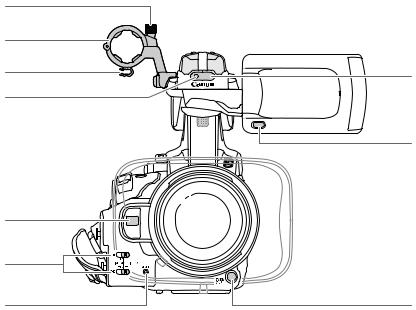
1 |
ZOOM SPEED switch for the handle zoom rocker |
11 |
SET button (028) |
||||
|
(076) |
|
|
12 |
CANCEL button (028) |
||
2 |
Side panel (048) |
|
|
13 |
CUSTOM PICT. (custom picture) button (0109) |
||
3 |
eswitches (092) |
14 |
PUSH AUTO IRIS button (067) |
||||
4 |
SLOT SELECT (CF card slot selection) button |
15 |
SHUTTER switch (064) |
||||
|
(040) |
|
|
16 |
Iris ring (066) |
||
5 |
CFj(CF card slot A) and CFl(CF card slot B) |
||||||
17 |
Zoom ring (074) |
||||||
|
access indicators (038) |
||||||
|
18 |
Distance indicator (052) |
|||||
6 |
edials for CH1 and CH2 (092) |
||||||
19 |
Focus ring (052) |
||||||
7 |
MENU button (028) |
|
|
||||
|
|
20 |
Lens hood (030) |
||||
8 |
STATUS button (0172) |
||||||
|
|
|
|||||
9SELECT dial (028)
10 FULL AUTO switch (045)
12

Names of Parts
Introduction |
1 |
|
|
Terminals |
1 |
2 3 |
|
4 |
|
|
|
|
|
|
5 6 |
|||||||||
(019) |
|
|
|
|
|
|
|
|
|
|
|
|
|
|
|
|
|
|
|
|
|
|
|
|
|
|
|
|
|
|
|
|
|
|
|
|
|
|
|
||
|
|
|
|
|
|
|
|
|
|
|
|
|
|
|
|
|
|
|
|
|
|
|
|
|
|
|
|
|
|
|
|
|
|
|
|
|
|
|
|
|
|
|
|
|
|
|
|
|
|
|
|
|
|
|
|
|
|
|
|
|
|
|
|
|
|
|
|
|
|
|
|
|
|
|
|
|
|
|
|
|
|
|
|
|
|
|
|
|
|
|
|
|
|
|
|
|
|
|
|
|
|
|
|
|
|
|
|
|
|
|
|
|
|
|
|
|
|
|
|
|
|
|
|
|
|
|
|
|
|
|
|
|
|
|
|
|
|
|
|
|
|
|
|
|
|
|
|
|
|
|
|
|
|
|
|
|
|
|
|
|
|
|
|
|
|
|
|
|
|
|
|
|
|
|
|
|
|
|
|
|
|
|
|
|
|
|
|
|
|
|
|
|
|
|
|
|
|
|
|
|
|
|
|
|
|
|
|
|
|
|
|
|
|
|
|
|
|
|
|
|
|
|
|
|
|
|
|
|
|
|
|
|
|
|
|
|
|
|
|
|
|
|
|
|
|
|
|
|
|
|
|
|
|
|
|
|
|
|
|
|
|
|
|
|
|
|
|
|
|
|
|
|
|
|
|
|
|
|
|
|
|
|
|
|
|
|
|
|
|
|
|
|
|
|
|
|
|
|
|
|
|
|
|
|
|
|
|
|
|
|
|
|
|
|
|
|
|
|
|
|
|
|
|
|
|
|
|
|
|
|
|
|
|
|
|
|
|
|
|
|
|
|
|
|
|
|
|
|
|
|
|
|
|
|
|
|
|
|
|
|
|
|
|
|
|
|
|
|
|
|
|
|
|
|
|
|
|
|
|
|
|
|
|
|
|
|
|
|
|
|
|
|
|
|
|
|
|
|
|
|
|
|
|
|
|
|
|
|
|
|
|
|
|
|
|
|
|
|
|
|
|
|
|
|
|
|
|
|
|
|
|
|
|
|
|
|
|
|
|
|
|
|
|
|
|
|
|
|
|
|
|
|
|
|
|
|
|
|
|
|
|
10 |
9 |
8 |
7 |
1 Speaker (0128)
2SD card slot cover
3 SD card access indicator (039)
4 SD card slot (039)
5PUSH button (052)
6Focus mode ring (052)
7Lens hood lock screw (030)
8XLR terminals (CH1 and CH2) (089)
9 AUDIO IN switches for CH1 and CH2 (088, 90) 10 Grip belt (034)
13
1 |
Introduction |
Names of Parts |
|
|
|
10 |
|
9 |
|
8 |
1 |
7 |
|
|
2 |
6
5
4 |
3 |
1 Remote sensor (036)
2MIRROR button (032)
3 START/STOP button (044)
4RESET button (0179)
5 XLR terminal switches for CH1 and CH2 (090) 6 Instant AF sensor (056)
7Front tally lamp (044)
8 Microphone cable clamp (089)
9Microphone holder (089)
10 Microphone lock screw (089)
14
Names of Parts
Introduction |
1 |
|
|
1 |
2 |
|
3 |
||
|
|
|
|
|
|
|
|
|
|
|
|
11
10 |
13 |
|
9 |
12 |
8
7
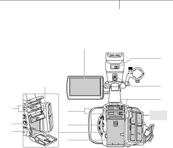
1 LCD screen (033)
2Viewfinder unit
3Viewfinder (031, 33)
4Dioptric adjustment lever (031)
5RELEASE (viewfinder release) switch (0188)
6 CF card slot cover switches for CF card slots A (top) and B (bottom) (037)
7Battery compartment cover (022)
8 BATT. RELEASE (battery release) switch (022)
9Battery compartment
10CF card slots A (top) and B (bottom) (037)
11CF card release buttons (038)
12BATT. OPEN (open battery compartment) switch (022)
13CF card slot covers for CF card slots A (top) and B (bottom)
4
5
6
Terminals
(019)
15

1 |
Introduction |
Names of Parts |
|
|
|
1 |
2 |
3 |
4 |
5 |
6 |
7 |
12 
|
Operation panel |
|
|
|
|
11 |
(018) |
7 |
10 |
9 |
8 |
1Accessory shoe
For attaching accessories such as the optional VL-10Li II Battery Video Light.
2Grip zoom rocker (075)
3 MAGN. (magnification) button (055)/Assignable button 6 (0107)
4START/STOP button (044)
5 U(review recording) button (0100)/Assignable button 5 (0107) 6 Handle socket for 0.64 cm (1/4") screws
7 Strap mount (034)
8dswitch (025)
9HEADPHONE +/- buttons (093)
10DISPLAY button (046)/BATT. INFO (battery information) button (022)
11Rear tally lamp (044)
12Built-in microphone (088)
16

Names of Parts
Introduction |
1 |
|
|
1
2
4 3
1 Attachment sockets for the optional TA-100 Tripod Adapter (036) 2 Attachment screws for the tripod base (036)
3Tripod socket (036)
4Tripod base for tripods with 0.64 cm (1/4") screws (036)
17

1 |
Introduction |
|
|
Operation panel
12
9
87
Operation panel
14
13
Operation panel
27
26
25
24
Names of Parts
|
1 |
PUSH AF button (057) |
|
|
2 |
FOCUS switch (053, 56) |
|
|
3 |
IS (image stabilizer) button (059)/ |
|
|
|
Assignable button 1 (0107) |
|
|
4 |
PEAKING button (055) / |
|
3 |
|
Assignable button 2 (0107) |
|
5 |
ZEBRA button (078)/ |
||
|
|||
4 |
|
Assignable button 3 (0107) |
|
6 |
WFM (waveform monitor) button (096)/ |
||
|
Assignable button 4 (0107)
57 IRIS switch (066)
8 ZOOM switch (074)
69 ND FILTER switch (069)
10 AWB (automatic white balance) switch (070)
11 S(white balance adjustment) button (071)
12 WHITE BAL. (white balance) switch (071)
13 GAIN switch (061)
14 AGC (automatic gain control) switch (060)
|
15 |
D(play/pause) button (0125)/ |
|
10 |
|
Assignable button 9 (0107) |
|
16 |
I(fast playback) button (0127)/ |
||
|
|||
|
|
Assignable button 10 (0107) |
|
11 |
17 |
B(stop) button (0125)/ |
|
12 |
|
Assignable button 12 (0107) |
|
18 |
K(skip forward) button (0127)/ |
||
|
|||
|
|
Assignable button 13 (0107) |
|
|
19 |
CANCEL button (028) |
|
|
20 |
Joystick (028)/SET button (028) |
|
15 |
21 |
START/STOP button (044) |
|
16 |
22 |
START/STOP lock lever (044) |
|
23 |
MAGN. (magnification) button (055)/ |
||
17 |
|
Assignable button 7 (0107) |
|
18 |
24 |
Handle zoom rocker (076) |
|
|
|||
19 |
25 |
INDEX button (0124)/ |
|
|
POWER SAVE button (050) |
||
20 |
26 |
L(skip backward) button (0127)/ |
|
|
Assignable button 11 (0107) |
||
21 |
|
||
27 |
J(fast reverse playback) button (0127)/ |
||
22 |
|
Assignable button 8 (0107) |
|
|
|
||
23 |
|
|
18

Names of Parts
Introduction |
1 |
|
|
Terminals |
1 |
DC IN terminal (024) |
|
1 |
2 |
bHD/SD SDI terminal (0142) |
|
3 |
bGENLOCK terminal (086) |
||
|
4 |
bTIME CODE terminal (087) |
|
|
5 |
VIDEO 2 terminal (0143) |
|
|
6 |
W(headphone) terminal (093) |
|
2 |
7 |
REMOTE terminal |
|
|
8 |
HD/SD COMPONENT OUT terminal (0142) |
|
3 |
9 |
HDMI OUT terminal (0142) |
|
10 |
USB terminal (0146) |
||
|
|||
|
11 |
AV terminal (0143) |
|
4 |
|
|
|
5 |
|
|
Terminals
6
11
7
10
9 |
8 |
19

1 |
Introduction |
Names of Parts |
|
|
|
WL-D6000 Wireless Controller |
|
|
|
1 |
|
14 |
|
|
13 |
2 |
|
12 |
||
11 |
|
|
10 |
3 |
|
|
||
9 |
4 |
|
8 |
||
|
||
7 |
5 |
|
|
6 |
1 START/STOP button (044)
2 ZOOM buttons (077)
3 F/O/E/Abuttons
4MENU button (028)
5 J/I(fast playback/reverse playback) buttons (0127) 6 Z/Y(frame forward/reverse) buttons (0127)
7B(stop) button (0125)
8 D(play/pause) button (0125)
9INDEX button (0124)
10SET button (028)
11CANCEL button (028)
12SHOT1 (shot mark 1) button (099)
13PHOTO button (0155)
14Record enable button: When you use the START/STOP button or ZOOM buttons, you must press this button simultaneously with the desired button.
20
Preparations
Preparing the Power Supply |
Preparations |
2 |
|
|
|
You can power the camcorder using a battery pack or directly using the compact power adapter. If you connect the compact power adapter to the camcorder while a battery pack is attached, the camcorder will draw power from the power outlet.
Charge battery packs before use. For approximate charging times and recording/playback times with a fully charged battery pack, refer to
Charging Times (0191) and Recording and Playback Times (0191).
Using a Battery Pack
You can power the camcorder using the supplied BP-955 or optional BP-975, BP-950G or BP-970G Battery Pack. The BP-955 and BP-975 Battery Packs are compatible with Intelligent System, meaning that you can check the remaining battery time.
Charging the Battery Pack
Charge battery packs using the supplied compact power adapter. Before charging, disconnect the DC cable from the compact power adapter and remove the terminal cover of the battery pack.
1If the DC cable is connected to the compact power adapter, disconnect it.
2 Connect the power cord to the compact power adapter ( ).
3 Plug the power cord into a power outlet ( ).
4Attach the battery pack to the compact power adapter ( ).
•Press lightly and slide the battery pack in the direction of the arrow until it clicks.
•The CHARGE indicator starts flashing and also indicates the battery pack’s approximate charge. The indicator will stay on when charging has completed.
 0-34%: Flashes once per second
 35-69%: Flashes twice per second
 70-99%: Flashes 3 times per second
5When charging has completed, remove the battery pack from the compact power adapter.


CHARGE indicator
21

2 |
Preparations |
|
|
|
Preparing the Power Supply
6Unplug the power cord from the power outlet and disconnect it from the compact power adapter.
 NOTES
NOTES
•To charge the battery pack, disconnect the DC cable from the compact power adapter.
•The supplied BP-955 and optional BP-975 Battery Packs are not compatible with previous Canon camcorder models.
Attaching the Battery Pack
1 Hold down the button on the dswitch and move it to OFF ( ).
2Slide the BATT. OPEN (open battery compartment) switch in the direction of the arrow and open the battery compartment cover ( ).
3Insert the battery pack all the way into the compartment and press gently until it clicks ( ).
4 Close the battery compartment cover.
Removing the Battery Pack
1 Hold down the button on the dswitch and move it to OFF.
2Slide the BATT. OPEN switch in the direction of the arrow and open the battery compartment cover.
3Press the BATT. RELEASE (battery release) latch in the direction of the arrow and pull out the battery.
4 Close the battery compartment cover.
CHECKbutton
0 
 100%
100% 
Battery charge indicator
Checking the Remaining Battery Charge
If you are using the supplied BP-955 or optional BP-975 Battery Pack, you can check the approximate remaining battery charge using one of the following methods when the camcorder is turned off. When the camcorder is turned on, you can check on the remaining battery charge by looking at any recording/playback screen or the [Battery / Hour Meter] status screen (0172).
Press the CHECK button on the battery pack. An indicator will light for approximately 3 seconds and show the approximate remaining battery charge.
22

Preparing the Power Supply |
Preparations |
2 |
|
|
|
0-25%
26-50%
51-75%
76-100%
When the camcorder is off and an Intelligent System-compatible battery pack is attached, press the BATT. INFO (battery information) button to display the remaining battery time and available recording time (displays for 5 seconds). Depending on the battery life, the battery information may not be displayed.
 IMPORTANT
• Do not connect to the compact power adapter any product that is not expressly recommended for use with this camcorder.
 NOTES
NOTES
• We recommend charging the battery pack in temperatures between 10 ºC and 30 ºC. Outside the temperature range of 0 ºC to 40 ºC, charging will not start.
• If there is a malfunction with the compact power adapter or battery pack, the charge indicator will go out and charging will stop.
•For handling precautions regarding the battery pack, refer to Battery Pack (0185).
•Charged battery packs continue to discharge naturally. Therefore, charge them on the day of use, or the day before, to ensure a full charge.
•We recommend that you prepare battery packs to last 2 to 3 times longer than you think you might need.
•The first time you use a battery pack, fully charge it and then use the camcorder until the battery pack is completely exhausted. Doing so will ensure that the remaining recording time will be displayed accurately.
•Repeatedly charging and discharging the battery pack will eventually shorten its battery life. When you are using the supplied BP-955 or optional BP-975 Battery Pack, you can check the battery life on the [Battery / Hour Meter] status screen (0176) or the battery information screen (press the BATT INFO. button while the camcorder is turned off). Fully charging the battery pack and then discharging it will give you a more accurate reading.
23

2 |
Preparations |
|
|
|
DC IN 
 terminal


Preparing the Power Supply
Using a Household Power Outlet
When Using the Supplied CA-930 Compact Power Adapter and DC-930 DC Cable:
1 Hold down the button on the dswitch and move it to OFF ( ).
2 Connect the DC cable to the DC IN terminal on the camcorder ( ).
3Connect the power cord to the compact power adapter and plug it into a power outlet ( ).
4 Connect the DC cable to the compact power adapter ( ).
 IMPORTANT
•Turn off the camcorder before connecting or disconnecting the compact power adapter.
 NOTES
NOTES
•When using the camcorder with a household power outlet, you can change the battery pack while the power is on.
When Using the Optional CA-920 Compact Power Adapter and DC-920 DC Coupler:
1 Hold down the button on the dswitch and move it to OFF ( ).
2 Attach the DC coupler to the camcorder ( ).
3Connect the power cord to the compact power adapter and plug it into a power outlet ( ).
4 Connect the DC coupler to the adapter ( ).
5 Close the battery compartment cover.
6Detach the DC coupler after use.
•Open the battery compartment cover, push the BATT. RELEASE latch left and pull out the DC coupler.
 IMPORTANT
•Turn off the camcorder before connecting or disconnecting the compact power adapter.
24
Preparing the Power Supply
Preparations |
2 |
|
|
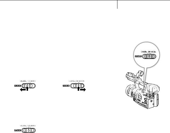
Turning the Camcorder On and Off
The camcorder has two operating modes: CAMERA ( ) mode for making recordings and MEDIA (
 ) mode for playing back recordings. Select the operating mode using the dswitch.
To turn on the camcorder
Hold down the button on the dswitch and move it to CAMERA for  mode or MEDIA for
  mode.
mode.
CAMERA mode |
MEDIA mode |
To turn off the camcorder
Hold down the button on the dswitch and move it to OFF.
25

2 |
Preparations |
Date, Time and Language Settings |
|
|
|
Setting the Date and Time
You will need to set the date and time of the camcorder before you can start using it. When the camcorder’s clock is not set, the [Date/Time] screen will appear automatically with the year selected.
Operating modes: 

1Push the joystick up/down or turn the SELECT dial to change the day then move (A) to the month.
2 Change the rest of the fields in the same way.
3Select (A) [Set] and then press SET to start the clock and close the screen.
 NOTES
NOTES
•When the built-in rechargeable lithium battery is exhausted, the date and time setting may be lost. In such case, recharge the built-in lithium battery (0187) and set the time zone, date and time again.
•You can change the date format and the clock format (12/24 hours) with the [JOther Functions]  [Clock Set]
  [Date Format] setting.
•You can also change the date and time later on (not during the initial
setup) with the [JOther Functions]  [Clock Set]
  [Date/Time] setting.
[JOther Functions]
[Time Zone]
[UTC+01:00 Paris]
Changing the Time Zone
Change the time zone to match the time zone of your location. The default setting is [UTC+01:00 Paris]. The time zones are based on Coordinated Universal Time (UTC).
Operating modes: 

1 Press the MENU button.
2 Push the joystick up/down or turn the SELECT dial to select [JOther Functions].
3 Select [Time Zone] in a similar fashion.
26

Date, Time and Language Settings
Preparations |
2 |
|
|
4Push the joystick up/down or turn the SELECT dial to change the time zone.
5Press SET to set the time zone and then press the MENU button to close the menu.
Displaying the Date and Time while Recording
You can display the date and time in the lower left of the screen.
Operating modes: 

1 Press the MENU button.
2 Push the joystick up/down or turn the SELECT dial to select [MLCD/VF Setup].
3 Select [Custom Display] and then [Date/Time] in a similar fashion.
4 Push the joystick up/down or turn the SELECT dial to select the information to display.
• Select [Off] to record without displaying the date and time.
5 Press SET and then press the MENU button to close the menu.
[MLCD/VF Setup]
[Custom Display]
[Date/Time]
[Date/Time]
Changing the Language
You can change the language in which onscreen messages are displayed. The default language is English but you can select German, Spanish, French, Italian, Polish, Russian, Simplified Chinese or Japanese. Menus and setting options, however, will always be displayed in English, regardless of the language setting.
Operating modes: 

1 Press the MENU button.
2 Push the joystick up/down or turn the SELECT dial to select [JOther Functions].
3 Select [Language o] in a similar fashion.
4 Push the joystick up/down or turn the SELECT dial to select a language.
5 Press SET to select the language and then press the MENU button to close the menu.
[JOther Functions]
[Language o]
[English]
27

2 |
Preparations |
Using the Menus |
|
|
|
In  mode, many of the camcorder’s functions can be adjusted from the menu for general settings, which opens after pressing the MENU button. In
  mode, press the MENU button to open the menu for general settings or SET to open the clip menu for clip operations. For details about the available menu options and settings, refer to Menu Options (0163).
Operating modes: 
CANCEL button
Joystick/SET button
Push the joystick to move the orange selection frame in the menu. Then, press the joystick itself (SET button) or the SET button next to the SELECT dial to select the menu item indicated by the orange selection frame.
MENU button
Press to open the menu and then press again to close the menu after adjusting desired settings.
CANCEL button |
SELECT dial |
Press to return to the previous menu or to |
Turn the dial to move the orange selection |
stop some operations that are in progress. |
frame up or down in the menu. |
Selecting an Option from the Menu
The following is a step-by-step explanation of how to select an option from the menu. In the procedures throughout the rest of this manual, opening and closing the menu is assumed and not included in the procedure.
1 Press the MENU button.
•The menu opens with the orange selection frame indicating the menu item that was selected the previous time the menu was closed (unless the camcorder was turned off).
2 Push the joystick up/down or turn the SELECT dial to select the desired submenu.
3 Push the joystick right or press SET.
•The orange selection frame will appear on a menu item in the submenu.
•Press the CANCEL button, push the joystick left, or select [a] to return to the previous submenu.
28

Using the Menus
Preparations |
2 |
|
|
4 Push the joystick up/down or turn the SELECT dial to select the desired menu item.
•If a submenu contains many menu items, a scroll bar will appear on the right side of the submenu indicating that you must scroll up or down to see other menu items.
•A Amark next to a menu item indicates another submenu. Repeat steps 3 and 4.
5 Push the joystick right or press SET.
•The orange selection frame will appear on a setting option.
•Press the CANCEL button to return to the previous submenu.
6 Push the joystick up/down or turn the SELECT dial to select the desired setting option and then press SET.
•Depending on the menu item, additional selections may be necessary.
7 Press the MENU button to close the menu.
 NOTES
NOTES
•Unavailable items may appear grayed out.
•Pressing the MENU button at any time closes the menu.
•When using the wireless controller, use the h, i, f, gand SET buttons in the same way as the camcorder’s joystick.
•You can check the current settings on the status screens (0172).
29

2 |
Preparations |
Preparing the Camcorder |
|
|
|
This section outlines the basic preparations for the camcorder such as attaching the lens hood, attaching/removing the eyecup, and adjusting the viewfinder and LCD screen.
|
Attaching the Lens Hood |
|
|
Attach the lens hood to protect the lens and reduce the amount of stray |
|
|
light that may hit the lens. |
|
|
|
|
|
1 Place the lens hood on the front of the lens so that the window |
|
|
for the external Instant AF sensor faces down ( ) and turn it 90 |
|
degrees clockwise ( ). |
||
|
•Be careful not to deform the lens hood.
•Make sure that the lens hood is aligned with the thread.
2 Tighten the lock screw ( ).
Attaching and Detaching the Eye Cup
Attaching the Eye Cup
Attach the eye cup so that it covers the rubber portion of the viewfinder unit.
• The dioptric adjustment lever can be operated even with the eye cup attached.
•For left eye use, attach the eye cup so that the protruding portion faces the opposite side.
30
 Loading...