

Page 1
Type 8694
Positioner Top Control Basic
Electropneumatic position controller
Operating Instructions
Page 2

We reserve the right to make technical changes without notice.
Technische Änderungen vorbehalten.
Sous réserve de modifications techniques.
© Bürkert Werke GmbH & Co. KG, 2008 - 2019
Operating Instructions 1909/10_EN-EN_00805886 / Original DE
Page 3
Type 8694
Positioner Type 8694
Table of ConTenTs
1 OPERATING INSTRUCTIONS ........................................................................................................................................................7
1.1 Symbols
Definition of term / abbreviation ...................................................................................................................................7
1.2
AUTHORIZED USE .............................................................................................................................................................................8
2
2.1 Restrictions
BASIC SAFETY INSTRUCTIONS .................................................................................................................................................9
3
GENERAL INFORMATION .............................................................................................................................................................10
4
Contact address ..................................................................................................................................................................10
4.1
4.2 Warranty
4.3 Trademarks
Information on the internet ............................................................................................................................................10
4.4
SYSTEM DESCRIPTION ................................................................................................................................................................11
5
Intended application area ...............................................................................................................................................11
5.1
Function of the positioner and combination with valve types ....................................................................11
5.2
......................................................................................................................................................................................7
...............................................................................................................................................................................8
...................................................................................................................................................................................10
............................................................................................................................................................................10
Features of the valve types ...........................................................................................................................................12
5.3
Structure of the positioner ............................................................................................................................................13
5.4
5.4.1 Representation ....................................................................................................................................13
5.4.2 Features ................................................................................................................................................14
5.4.3 Function diagram of the positioner with single-acting actuator .............................................. 15
Type 8694 positioner (position controller) ............................................................................................................16
5.5
5.5.1 Schematic representation of the position control Type 8694 ..................................................16
5.5.2 Functions of the position controller software ............................................................................... 17
Interfaces of the positioner ..........................................................................................................................................19
5.6
TECHNICAL DATA .............................................................................................................................................................................20
6
6.1 Conformity
6.2 Standards
6.3 Licenses
Operating conditions ........................................................................................................................................................20
6.4
..............................................................................................................................................................................20
................................................................................................................................................................................20
...................................................................................................................................................................................20
3
english
Page 4

Type 8694
6.5 Mechanical data ...................................................................................................................................................................20
Pneumatic data ....................................................................................................................................................................21
6.6
Type labels ..............................................................................................................................................................................21
6.7
6.7.1 Type label standard ............................................................................................................................21
6.7.2 UL type label ........................................................................................................................................22
6.7.3 UL additional label ..............................................................................................................................22
Electrical data .......................................................................................................................................................................22
6.8
6.8.1 Electrical data without bus control 24 V DC ...............................................................................22
6.8.2 Electrical data with AS-Interface bus control ..............................................................................23
Factory settings of the positioner ..............................................................................................................................24
6.9
CONTROL AND DISPLAY ELEMENTS ...................................................................................................................................25
7
Operating status ...................................................................................................................................................................... 25
7.1
Control and display elements of the positioner .................................................................................................25
7.2
Configuration of the keys ................................................................................................................................................... 27
7.3
Function of the DIP switches ........................................................................................................................................... 29
7.4
Display of the LEDs ............................................................................................................................................................... 31
7.5
Error messages ....................................................................................................................................................................... 32
7.6
7.6.1 Error messages in MANUAL and AUTOMATIC operating statuses .........................................32
7.6.2 Error messages while the X.TUNE function is running ..............................................................32
8 INSTALLATION
Safety instructions .............................................................................................................................................................33
8.1
Installation of the positioner Type 8694 on process valves of series 2103, 2300 and 2301 .....33
8.2
Installing the positioner Type 8694 on process valves belonging to series 26xx and 27xx .......... 36
8.3
Rotating the actuator module ......................................................................................................................................40
8.4
Rotating the positioner for process valves belonging to series 26xx and 27xx ...............................42
8.5
...................................................................................................................................................................................33
PNEUMATIC INSTALLATION .......................................................................................................................................................43
9
Manual actuation of the actuator via pilot valves ..............................................................................................44
9.1
9.1.1 Single-acting actuators (control function A and B) ....................................................................44
ELECTRICAL INSTALLATION 24 V DC ...................................................................................................................................46
10
Safety instructions .............................................................................................................................................................46
10.1
4
english
Page 5

Type 8694
10.2 Electrical installation with circular plug-in connector .....................................................................................46
10.2.1 Designation of the contacts Type 8694 ........................................................................................ 46
10.2.2 Connection of the positioner Type 8694 ......................................................................................47
Electrical installation with cable gland ....................................................................................................................48
10.3
AS-INTERFACE INSTALLATION ................................................................................................................................................51
11
AS-Interface connection .................................................................................................................................................51
11.1
Maximum length of the bus line .................................................................................................................................51
11.2
Technical data for AS-Interface PCBs .....................................................................................................................51
11.3
Programming data ..............................................................................................................................................................52
11.4
Communication sequence for the version S-7.A.5 profile ..........................................................................53
11.5
LED status display ..............................................................................................................................................................54
11.6
Electrical installation AS-interface ............................................................................................................................55
11.7
11.7.1 Safety instructions ..............................................................................................................................55
11.7.2 Connection with circular plug-in connector M12 x 1, 4-pole, male .......................................56
11.7.3 Connection with multi-pole cable and ribbon cable terminal ...................................................56
12 START-UP
12.1
12.2
.............................................................................................................................................................................................58
Safety instructions .............................................................................................................................................................58
Specifying the standard settings ................................................................................................................................58
12.2.1 Running the automatic adjustment X.TUNE .........................................................................58
OPERATION AND FUNCTION ....................................................................................................................................................61
13
Basic functions ........................................................................................................................................................................ 61
13.1
13.1.1 DIR.CMD -
Effective direction of the positioner set-point value ...................................................................62
13.1.2 CUTOFF -
Sealing function for the positioner .................................................................................................63
13.1.3 CHARACT -
Select the transfer characteristic between input signal (position set-point value) and
stroke ..................................................................................................................................................... 64
13.1.4 INPUT -
Enter the input signal .........................................................................................................................66
13.1.5 RESET -
Reset to factory settings ...................................................................................................................67
13.1.6 X.TUNE -
Automatic adjustment of the positioner to the relevant operating conditions ......................67
5
english
Page 6
Type 8694
13.2 Auxiliary functions .................................................................................................................................................................. 68
13.2.1 DIR.ACTUATOR -
Effective direction of the actuator ................................................................................................... 68
13.2.2 SPLITRANGE -
Signal split range ................................................................................................................................69
13.2.3 X.LIMIT -
Limiting the mechanical stroke range ............................................................................................70
13.2.4 X.TIME -
Limiting the control speed ................................................................................................................71
13.2.5 X.CONTROL -
Parameterization of the positioner .................................................................................................. 72
13.2.6 SAFE POSITION -
Definition of the safe position .......................................................................................................... 72
13.2.7 SIGNAL ERROR -
Configuration of signal level fault detection ................................................................................. 73
13.2.8 BINARY INPUT -
Activation of the binary input ........................................................................................................... 73
13.2.9 OUTPUT (optional) -
Configuration of the analog output ................................................................................................ 74
SAFETY END POSITIONS ............................................................................................................................................................75
14
Safety end positions after failure of the electrical or pneumatic auxiliary power ...........................75
14.1
15 MAINTENANCE
Safety instructions .............................................................................................................................................................76
15.1
Service at the air intake filter .......................................................................................................................................77
15.2
16 ACCESSORIES
Communications software .............................................................................................................................................78
16.1
..................................................................................................................................................................................76
..................................................................................................................................................................................78
16.1.1 USB interface ......................................................................................................................................78
16.1.2 Download ............................................................................................................................................. 78
17 DISASSEMBLY
...................................................................................................................................................................................79
Safety instructions .............................................................................................................................................................79
17.1
Disassembly the positioner ...........................................................................................................................................79
17.2
PACKAGING AND TRANSPORT ...............................................................................................................................................81
18
19 STORAGE
20 DISPOSAL
6
..............................................................................................................................................................................................81
............................................................................................................................................................................................81
english
Page 7
Type 8694
Operating instructions
1 OPERATING INSTRUCTIONS
The operating instructions describe the entire life cycle of the device. Keep these instructions in a location which is
easily accessible to every user, and make these instructions available to every new owner of the device.
Important safety information.
Read the operating instruction carefully and thoroughly. Study in particular the chapters entitled “Basic safety
instructions” and “Authorized use”.
▶ The operating instructions must be read and understood.
1.1 Symbols
DANGER!
Warns of an immediate danger.
▶ Failure to observe the warning will result in a fatal or serious injury.
WARNING!
Warns of a potentially dangerous situation.
▶ Failure to observe the warning may result in serious injuries or death.
CAUTION!
Warns of a possible danger.
▶ Failure to observe this warning may result in a moderate or minor injury.
NOTE!
Warns of damage to property.
• Failure to observe the warning may result in damage to the device or the equipment.
Indicates important additional information, tips and recommendations.
refers to information in these operating instructions or in other documentation.
▶ Designates an instruction to prevent risks.
→ Designates a procedure which you must carry out.
1.2 Definition of term / abbreviation
The term “device” used in these instructions always stands for the positioner Type 8694.
In these instructions, the abbreviation “Ex” always refers to “potentially explosive”.
english
7
Page 8
Type 8694
Authorized use
2 AUTHORIZED USE
Non-authorized use of the positioner Type 8694 may be a hazard to people, nearby equipment and the
environment.
The device is designed to be mounted on pneumatic actuators of process valves for the control of media.
▶ Do not expose the device to direct sunlight.
▶ Use according to the authorized data, operating conditions and conditions of use specified in the contract
documents and operating instructions. These are described in the chapter entitled “6 Technical data”.
▶ The device may be used only in conjunction with third-party devices and components recommended and
authorized by Bürkert.
▶ In view of the large number of options for use, before installation, it is essential to study and if necessary to
test whether the positioner is suitable for the actual use planned.
▶ Correct transportation, correct storage and installation and careful use and maintenance are essential for reli-
able and faultless operation.
▶ Use the positioner Type 8694 only as intended.
2.1 Restrictions
If exporting the system/device, observe any existing restrictions.
8
english
Page 9
Type 8694
Basic safety instructions
3 BASIC SAFETY INSTRUCTIONS
These safety instructions do not make allowance for any
• contingencies and events which may arise during the installation, operation and maintenance of the devices.
• local safety regulations – the operator is responsible for observing these regulations, also with reference to the
installation personnel.
DANGER!
Risk of injury from high pressure in the equipment/device.
▶ Before working on equipment or device, switch off the pressure and deaerate/drain lines.
Risk of electric shock.
▶ Before working on equipment or device, switch off the power supply and secure to prevent reactivation.
▶ Observe applicable accident prevention and safety regulations for electrical equipment.
General hazardous situations.
To prevent injury, ensure:
▶ In the potentially explosion-risk area the positioner Type 8694 may be used only according to the specification
on the separate approval sticker. For use observe the additional instructions enclosed with the device together
with safety instructions for the explosion-risk area.
▶ Devices without a separate approval sticker may not be used in a potentially explosive area.
▶ That the system cannot be activated unintentionally.
▶ Installation and repair work may be carried out by authorized technicians only and with the appropriate tools.
▶ After an interruption in the power supply or pneumatic supply, ensure that the process is restarted in a defined
or controlled manner.
▶ The device may be operated only when in perfect condition and in consideration of the operating instructions.
▶ The general rules of technology apply to application planning and operation of the device.
To prevent damage to property on the device, ensure:
▶ Do not feed any aggressive or flammable media into the pilot air port.
▶ Do not feed any liquids into the pilot air port.
▶ When unscrewing and screwing in the body casing or the transparent cap, do not hold the actuator of the pro-
cess valve but the connection housing of Type 8694.
▶ Do not put any loads on the housing (e.g. by placing objects on it or standing on it).
▶ Do not make any external modifications to the device bodies. Do not paint the housing parts or screws.
english
9
Page 10
Type 8694
Basic safety instructions
NOTE!
Electrostatic sensitive components / modules.
The device contains electronic components, which react sensitively to electrostatic discharge (ESD). Contact
with electrostatically charged persons or objects is hazardous to these components. In the worst case scenario,
they will be destroyed immediately or will fail after start-up.
▶ Observe the requirements in accordance with EN 100 015 - 1 and to minimize or avoid the possibility of damage
caused by sudden electrostatic discharge.
▶ Also ensure that you do not touch electronic components when the power supply is on.
4 GENERAL INFORMATION
4.1 Contact address
Germany
Bürkert Fluid Control System
Sales Center
Chr.-Bürkert-Str. 13-17
D-74653 Ingelfingen
Tel. + 49 (0) 7940 - 10 91 111
Fax + 49 (0) 7940 - 10 91 448
E-mail: info@burkert.com
International
Contact addresses can be found on the final pages of the printed operating instructions.
And also on the Internet at:
www.burkert.com
4.2 Warranty
The warranty is only valid if the positioner Type 8694 is used as intended in accordance with the specified application conditions.
4.3 Trademarks
10
Brands and trademarks listed below are trademarks of the corresponding companies / associations / organizations
Loctite Henkel Loctite Deutschland GmbH
4.4 Information on the internet
The operating instructions and data sheets for Type 8694 can be found on the Internet at:
www.burkert.com
english
Page 11
Type 8694
System description
5 SYSTEM DESCRIPTION
5.1 Intended application area
The positioner Type 8694 is designed to be mounted on pneumatic actuators of process valves for the control of
media.
5.2 Function of the positioner and combination with
valve types
Positioner Type 8694 is an electropneumatic position controller for pneumatically actuated control valves with
single-acting actuators.
Together with the pneumatic actuator, the positioner forms a functional unit.
The control valve systems can be used for a wide range of control tasks in fluid technology and, depending on the
application conditions, different process valves belonging to series 2103, 2300, 2301, 26xx or 27xx from the Bürkert
range can be combined with the positioner. Angle-seat valves, diaphragm valves or ball valves fitted with a control
cone are suitable.
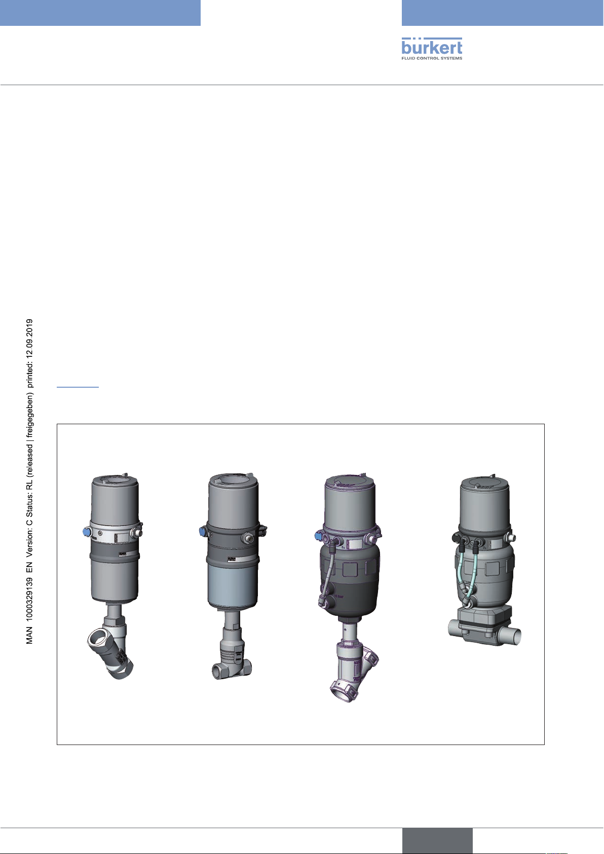
“Figure 1” shows an overview of the possible combinations of positioner and different pneumatically actuated valves.
Different actuator sizes and valve nominal widths, not illustrated here, are available for each type. More precise
specifications can be found on the respective data sheets. The product range is being continuously expanded.
Positioner Type 8694
with diaphragm
valve
with angle seat valve
Type 2300
Figure 1: Overview of possible combinations
with straight seat valve
Type 2301
Type 2730
with angle seat valve
Type 2702
11
english
Page 12
Type 8694
System description
The position of the actuator is regulated according to the position set-point value. The position set-point value is
specified by an external standard signal.
Pneumatically actuated piston actuators and rotary actuators can be used as an actuator. Single-acting actuators
are offered in combination with the positioner.
For single-acting actuators, only one chamber is aerated and deaerated in the actuator. The generated pressure works
against a spring. The piston moves until there is an equilibrium of forces between compressive force and spring force.
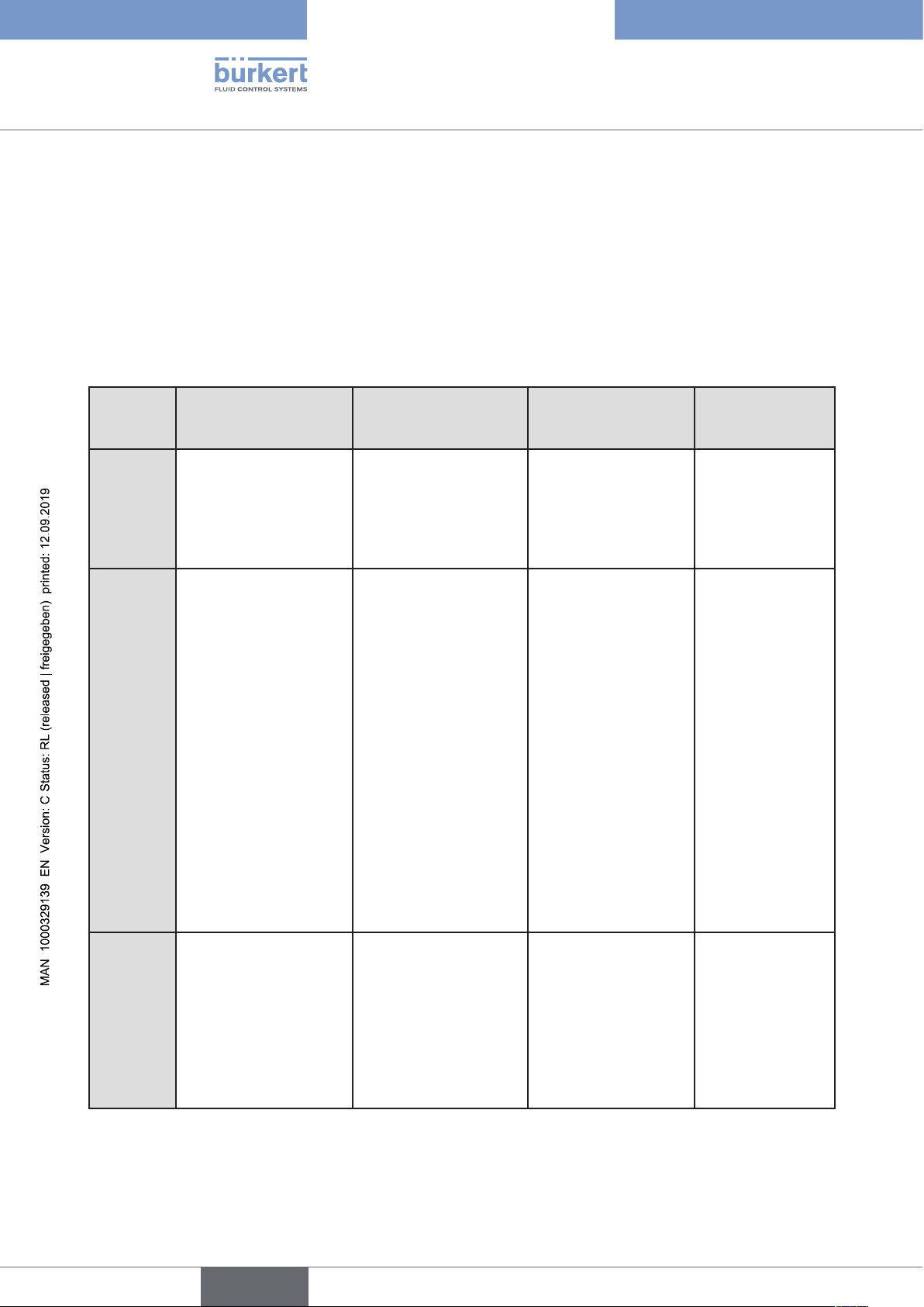
5.3 Features of the valve types
Types
Features
Angle seat control
valves / straight seat
control valves
• 2300
• 2301
• 2702
• 2712
• incoming flow under
seat
• no closing impact
• straight flow path of
the medium
• self-adjusting
stuffing box for high
leak-tightness
Diaphragm valves Ball valves Flap valves
• 2103
• 2730
• 2731
• medium is hermetically separated from
the actuator and
environment
• cavity-free and selfdraining body design
• any flow direction with
low-turbulence flow
• steam-sterilizable
• CIP-compliant
• no closing impact
• 2652
• 2655
• 2658
• scrapable
• minimum dead space
• unaffected by
contamination
• little pressure loss
compared to other
valve types
• seat and seal can
be exchanged in the
three-piece ball valve
when installed
• 2672
• 2675
• unaffected by
contamination
• little pressure
loss compared to
other valve types
• inexpensive
• low construction
volume
12
Typical
media
Table 1: Features of the valve types
• water, steam and
gases
• alcohols, oils, propellants, hydraulic fluids
• salt solutions, lyes
(organic)
• solvents
english
• actuator and diaphragm can be
removed when the
body is installed
• neutral gases and
liquids
• contaminated,
abrasive and
aggressive media
• media of higher
viscosity
Note
can be used as
process controller only
• neutral gases and
liquids
• clean water
• slightly aggressive
media
• neutral gases
and liquids
• slightly
aggressive media
Page 13
Type 8694
System description
5.4 Structure of the positioner
The positioner Type 8694 consists of the micro-processor controlled electronics, the position measuring system
and the control system. The device is designed using three-wire technology. The positioner is operated via 2 keys
and a 4-pole DIP switch. The pneumatic control system for single-acting actuators consists of 2 solenoid valves.
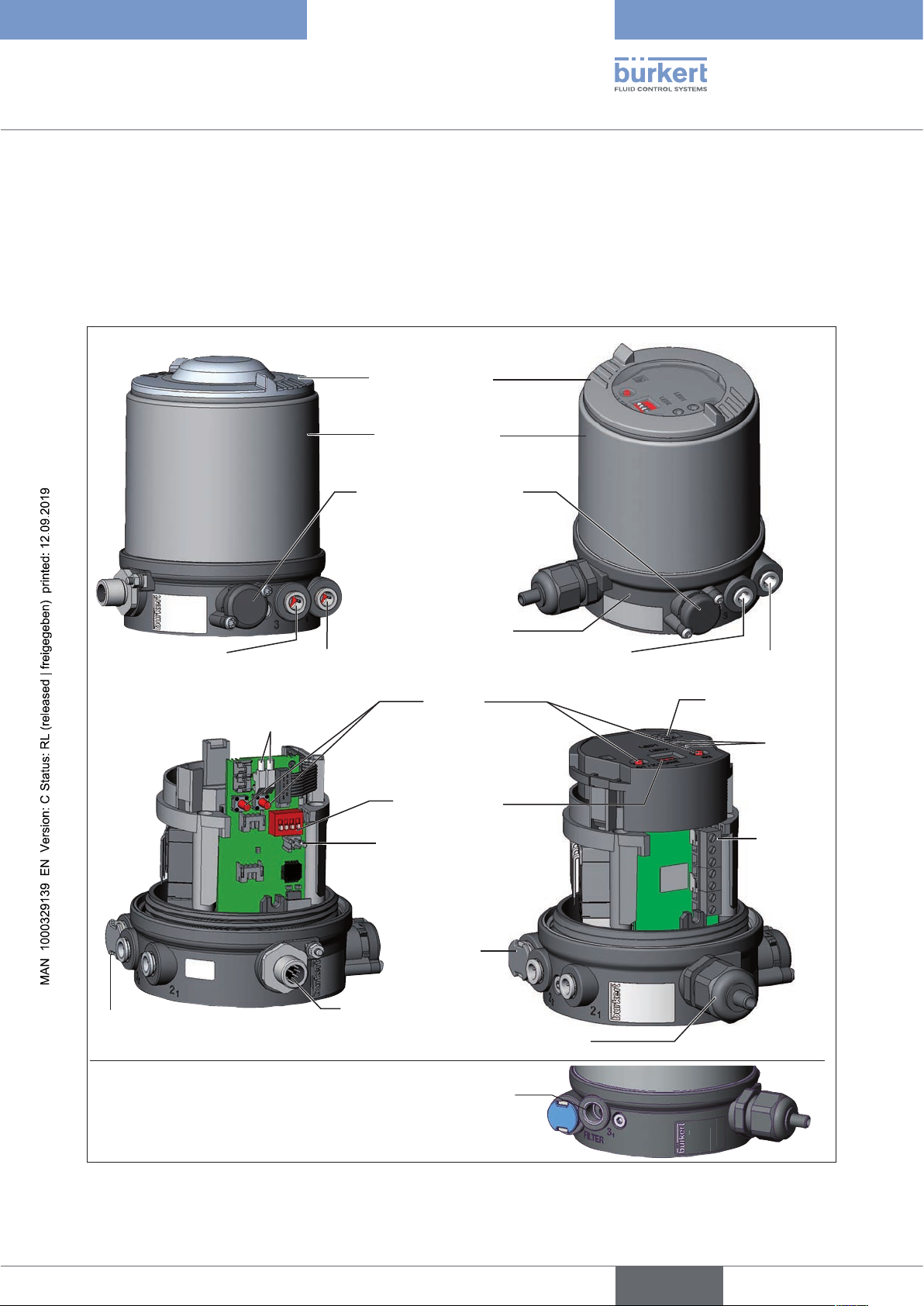
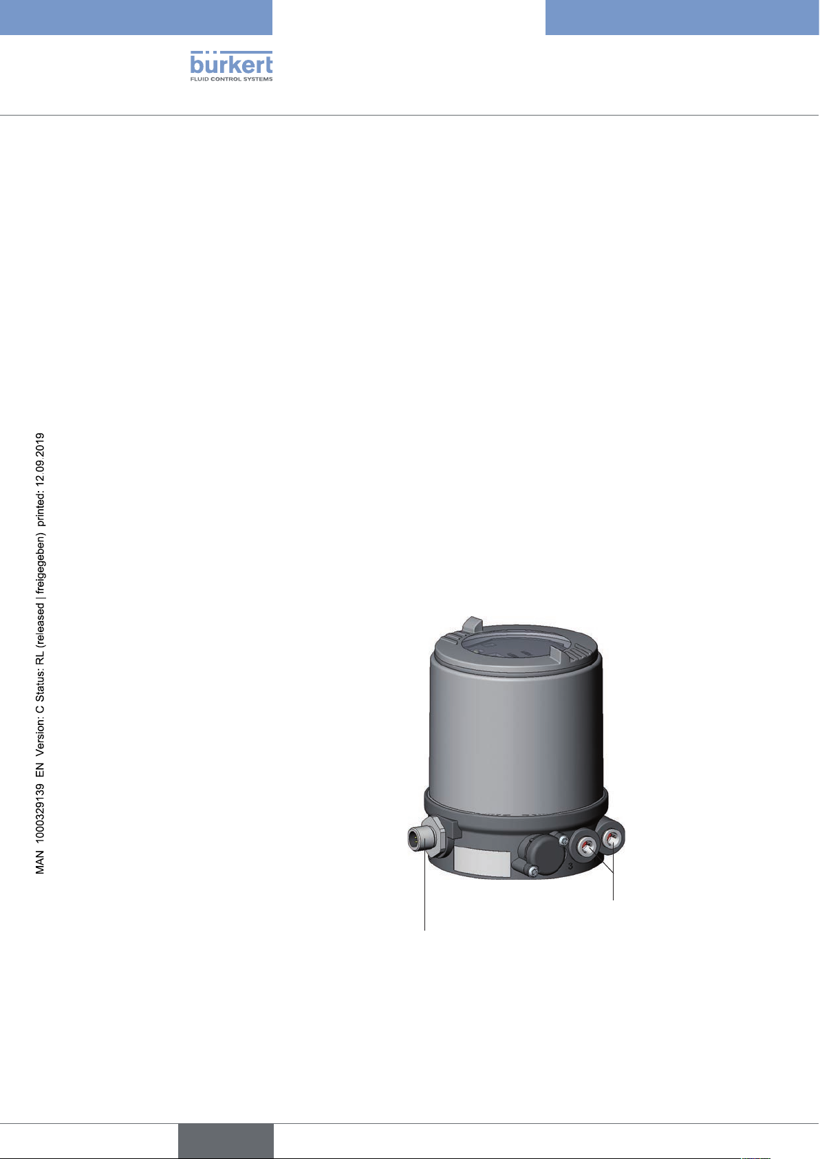
5.4.1 Representation
Version 1
Exhaust air connection (label: 3)
Body casing removed:
Transparent cap
Body casing
Pressure limiting valve
(for protection against too
high internal pressure in
case of error)
Connection housing
Pressure supply connection
(label: 1)
LED
Buttons
Version 2
Exhaust air connection (label: 3)
Pressure supply
connection (label: 1)
Communications
interface
LED
Air intake filter
(exchangeable)
with pilot-operated control system for high air flow rate
Figure 2: Structure
DIP Switches
Communications
interface
Air intake
filter
(exchangeable)
Electrical connection
(cable gland M16 x 1.5
or circular plug-in connector M12 x 1)
Additional exhaust air port (label: 3.1)
only for Type 23xx and 2103
(actuator size ø 130)
Screwtype
terminals
13
english
Page 14
Type 8694
System description
5.4.2 Features
• Models
for single-acting valve actuators.
• Position measuring system
Contactless and therefore wear-free position measuring system.
• Microprocessor-controlled electronics
for signal processing, control and valve control.
• Control module
The device is controlled via 2 buttons and a 4-pole DIP switch. 2x 2-colored LEDs indicate different statuses of
the device.
• Control system
The control system consists of 2 solenoid valves. One valve is used to aerate and another to deaerate the
pneumatic actuator. The solenoid valves operate according to the rocker principle and are controlled with a
PWM voltage via the controller. Doing so achieves a higher flexibility with regard to actuator volume and final
control speed. The direct-action model has an orifice of DN 0.6. In larger pneumatic actuators the solenoid
valves feature diaphragm amplifiers to increase the maximum flow and therefore to improve the dynamics (DN
2.5).
• Position feedback (optional)
The position of the valve can be transmitted to the PLC via an analog 0/4-20 mA output.
• Binary input
If a voltage > 10 V is applied, SAFE POSITION is activated, i.e. the valve is moved to the safety position
(factory setting, can be changed with communications software).
• Pneumatic interfaces
1/4“ connections with different thread forms
(G, NPT)
hose plug-in connection
• Electrical interfaces
Circular plug-in connector or cable gland
Pneumatic interface
14
Electrical interface
• Body
The body of the positioner is protected from excessively high internal pressure, e.g. due to leaks, by a pressure
limiting valve.
• Communications interface
For configuration and parameterization.
english
Page 15
Type 8694
System description
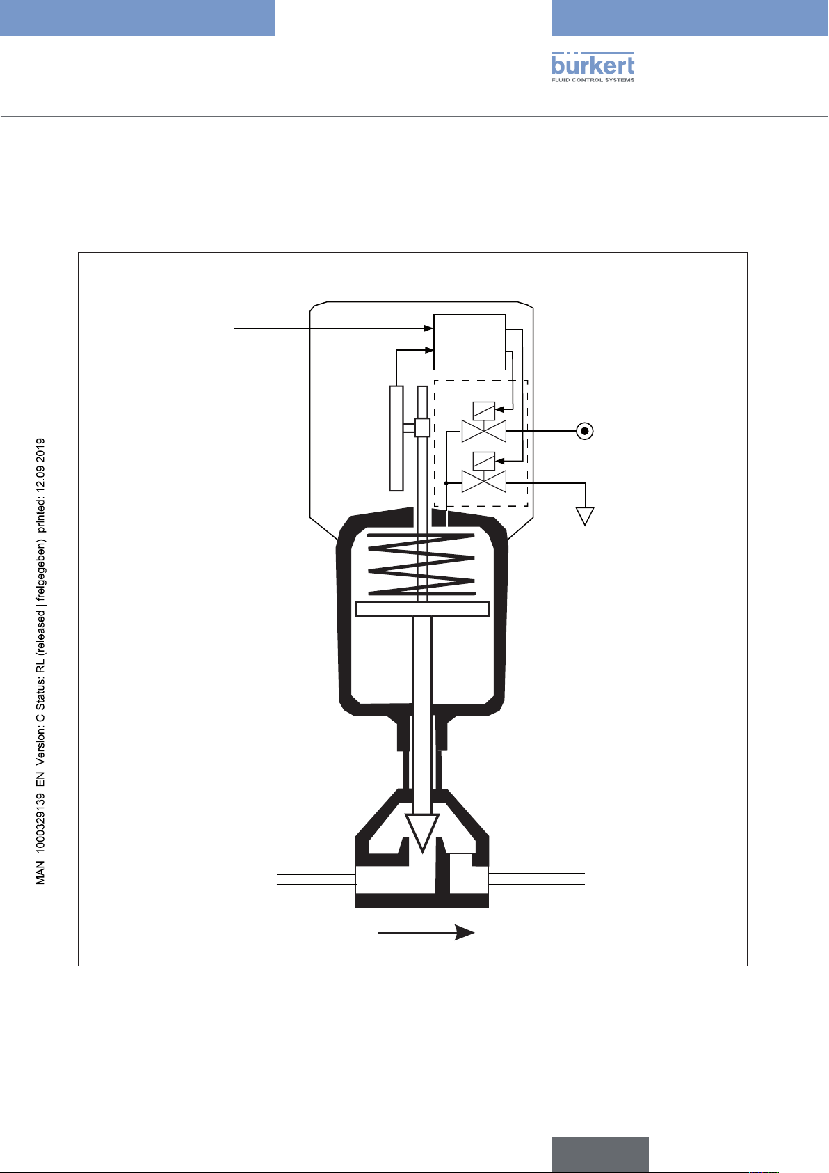
5.4.3 Function diagram of the positioner with single-acting actuator
The illustrated function diagram describes the function of the positioner (Type 8694).
external
position
set-point value
Position
controller
Control system
1
2
Control system
1: Aeration valve
2: Bleed valve
Pressure
supply
Positioner
Actual
position
Position
measuring
system
Pneumatic actuator
(single-acting)
Valve
(actuator)
Exhaust air
Figure 3: Function diagram
15
english
Page 16
Type 8694
System description
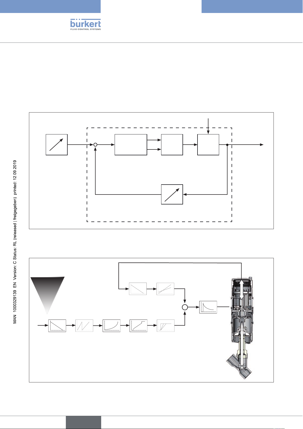
5.5 Type 8694 positioner (position controller)
The position measuring system records the current position (POS) of the pneumatic actuator. The position controller
compares this actual position value with the set-point value (CMD) which is definable as standard signal. In case
of a control deviation (Xd1), a pulse-width modulated voltage signal is sent to the control system as a manipulated variable. If there is a positive control difference in single-acting actuators, the air inlet valve is controlled via
output B1. If the control difference is negative, the bleed valve is controlled via output E1. In this way the position
of the actuator is changed until control difference is 0. Z1 represents a disturbance variable.
Z1
B1
Position
set-point
CMD Xd1
+
-
Position
controller
E1
Solenoid valves
P
K
Valve opening
Control valveControl system
value
POS
Position control
circuit
Position measuring system
Figure 4: Signal flow plan of position controller
5.5.1 Schematic representation of the position control Type 8694
16
4 ... 20 mA1)
0 ... 20 mA
DIR.ACT
INP
DIR.CMD
1) Default setting
2) Can only be activated with communications software
Figure 5: Schematic representation of position control
SPLTRNG
2)
CHARACT
CUTOFF
english
2)
X.LIMIT
X.TIME
POS
2)
CMD
2)
POS
CMD
X.CONTROL
DBND
Page 17
Type 8694
System description
5.5.2 Functions of the position controller software
Functions I
• Activation via DIP switches
• Parameter setting via communications software
Additional function Effect
Sealing function
CUTOFF
Correction line to adjust the operating characteristic
CHARACT
Effective direction of the controller set-point value
DIR.CMD
Table 2: Functions I
Valve closes tight outside the control range. Specification
of the value (as %), from which the actuator is completely
deaerated (when 0 %) or aerated (when 100 %)
(see chapter “7.4 Function of the DIP switches”).
Linearization of the operating characteristic can be implemented (see chapter “7.4 Function of the DIP switches”).
Reversal of the effective direction of the set-point value
(see chapter “7.4 Function of the DIP switches”).
english
17
Page 18
Functions II
• Activation and parameter setting via communications software
Additional function Effect
Type 8694
System description
Standard signal for set-point value
INPUT
Effective direction of the actuator
DIR.ACTUATOR
Signal split range
SPLITRANGE
Mechanical stroke range limit
X.LIMIT
Opening and closing time
X.TIME
Position controller
X.CONTROL
Safety position
SAFE POSITION
Select set-point value standard signal
Assignment of the aeration status of the actuator
chamber to the actual position.
Standard signal as % for which the valve runs through
the entire mechanical stroke range.
Limit the mechanical stroke range
Limit the control speed
Parameterize the position controller
Definition of the safety position
18
Signal level fault detection
Configuration of signal level fault detection
SIGNAL ERROR
Binary input
Configuration of the binary input
BINARY INPUT
Analog output
Configuration of the analog output (optional)
OUTPUT
Reset
Reset to factory settings
RESET
Table 3: Functions II
english
Page 19
Type 8694
System description
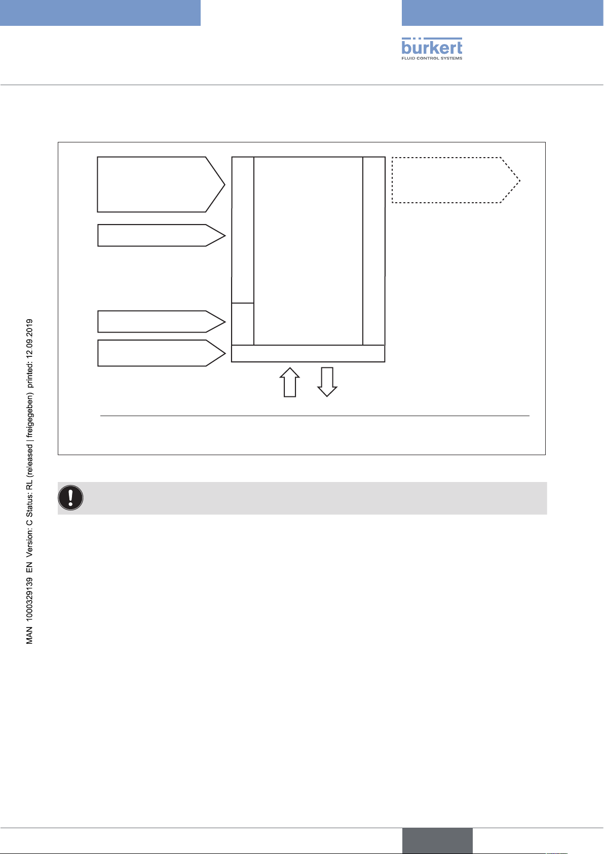
5.6 Interfaces of the positioner
Input for position
set-point value3)
4 – 20 mA4)
0 – 20 mA
Binary input
24 V DC
Communications
interface
3) Or optional bus connection AS interface
4) Default setting
Inputs
Power
Positioner
Operation
Analog
position feedback
(optional)
Outputs
Figure 6: Interfaces
The positioner Type 8694 is a 3-wire device, i.e. the power (24 V DC) is supplied separately from the setpoint value signal.
• Input for position set-point value (4 – 20 mA corresponds to 0 – 100 %
(depending on position of DIP switch 1)).
• Binary input
If a voltage > 10 V is applied, SAFE POSITION is activated, i.e. the valve is moved to the safety position
(factory setting, can be changed with communications software).
• Analog position feedback (optional)
The position of the valve can be transmitted via an analog 4 – 20 mA output to the PLC
(4 – 20 mA corresponds to 0 – 100 %).
english
19
Page 20
Type 8694
Technical data
6 TECHNICAL DATA
6.1 Conformity
In accordance with the EU Declaration of conformity, the positioner Type 8694 is compliant with the EU Directives.
6.2 Standards
The applied standards on the basis of which compliance with the EU Directives is confirmed are listed in the EU
type examination certificate and/or the EU Declaration of Conformity.
6.3 Licenses
The product is approved for use in zone 2 and 22 in accordance with ATEX directive 2014/34/EU category 3GD.
Observe instructions on operation in an explosion-risk (Ex) area.
Observe the ATEX additional instructions.
The product is cULus approved. Instructions for use in the UL area see chapter “6.8 Electrical data”.
6.4 Operating conditions
WARNING!
Solar radiation and temperature fluctuations may cause malfunctions or leaks.
▶ If the device is used outdoors, do not expose it unprotected to the weather conditions.
▶ Ensure that the permitted ambient temperature does not exceed the maximum value or drop below the mini-
mum value.
Ambient temperature see type label
Degree of protection
Evaluated by the manufacturer: Evaluated by UL:
IP65 / IP67 according to EN 60529 * UL Type 4x Rating *
Operating altitude up to 2000 m above sea level
20
* Only if cables, plugs and sockets have been connected correctly and in compliance with the exhaust air concept see chapter
“9 Pneumatic installation”.
6.5 Mechanical data
Dimensions See data sheet
Body material exterior: PPS, PC, VA,
interior: PA 6; ABS
Sealing material EPDM / (NBR)
Stroke range of valve spindle: 2 – 45 mm
english
Page 21
Type 8694
Technical data
6.6 Pneumatic data
Control medium neutral gases, air
Quality classes in accordance with ISO 8573-1
Dust content Quality class 7 max. particle size 40 µm, max. particle density 10 mg/m³
Water content Quality class 3 max. pressure dew point
- 20 °C or min. 10 °C below the lowest operating temperature
Oil content Quality class X max. 25 mg/m³
Temperature range
of the control medium -10 – +50 °C
Pressure range
of the control medium 3 – 7 bar
Air output of pilot valve 7 lN / min (for aeration and deaeration)
(QNn - value according to definition for pressure drop from 7 to 6 bar
absolute)
optional: 130 lN / min (for aeration and deaeration)
(only single-acting)
Connections Plug-in hose connector Ø6 mm / 1/4"
Socket connection G1/8
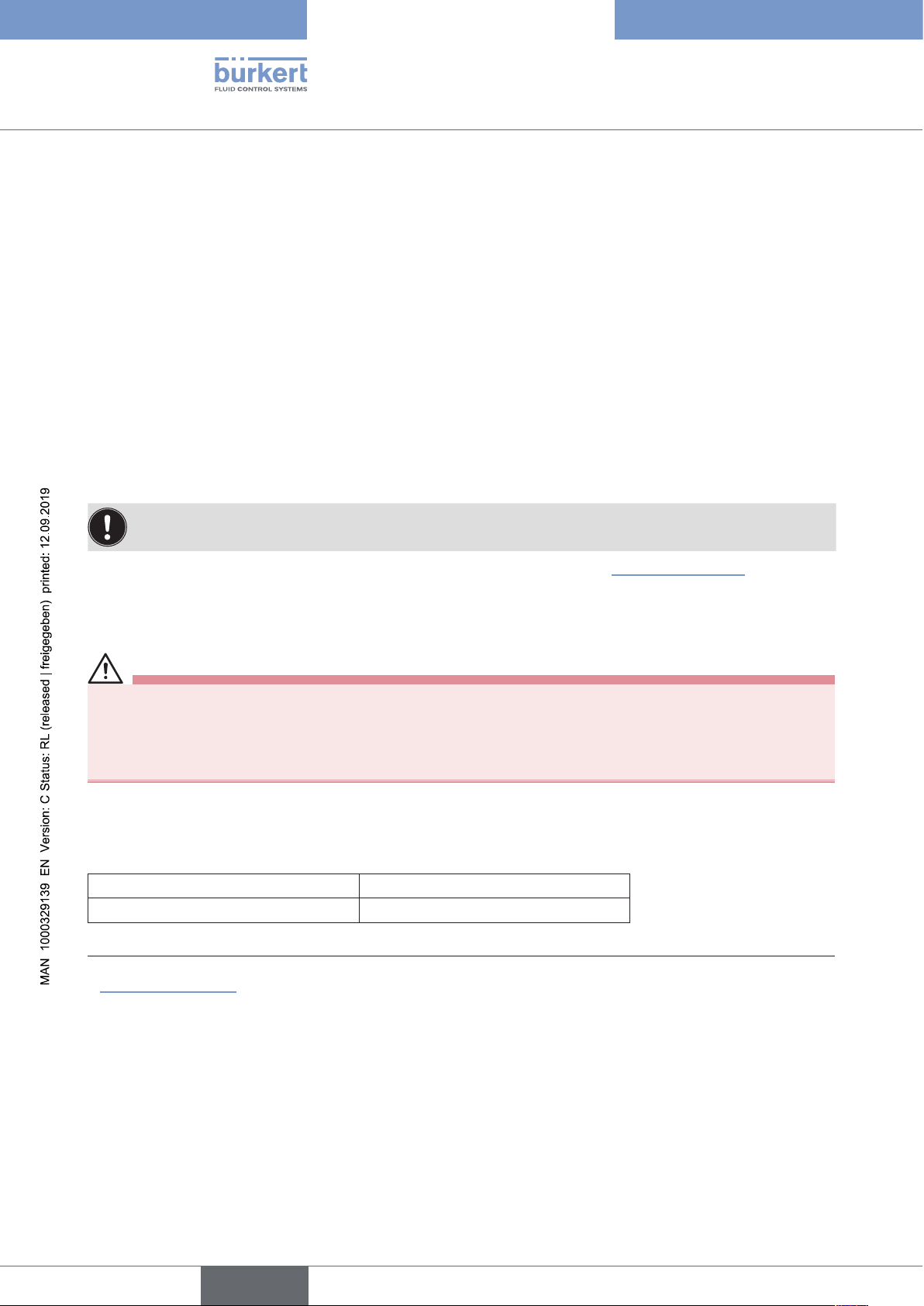
6.7 Type labels
6.7.1 Type label standard
Example:
Supply voltage / Control
Type
8694 24 V DC
single act Pilot 0,6
Pmax 7bar
Tamb 0°C - +60°C
S/N 001000
00185134
D-74653 Ingelfingen
Identification number
W14UN
CE
Control function - Pilot valve
Max. operating pressure
Max. ambient temperature
Serial number - CE mark
Bar-code
Figure 7: Example of type label
21
english
Page 22
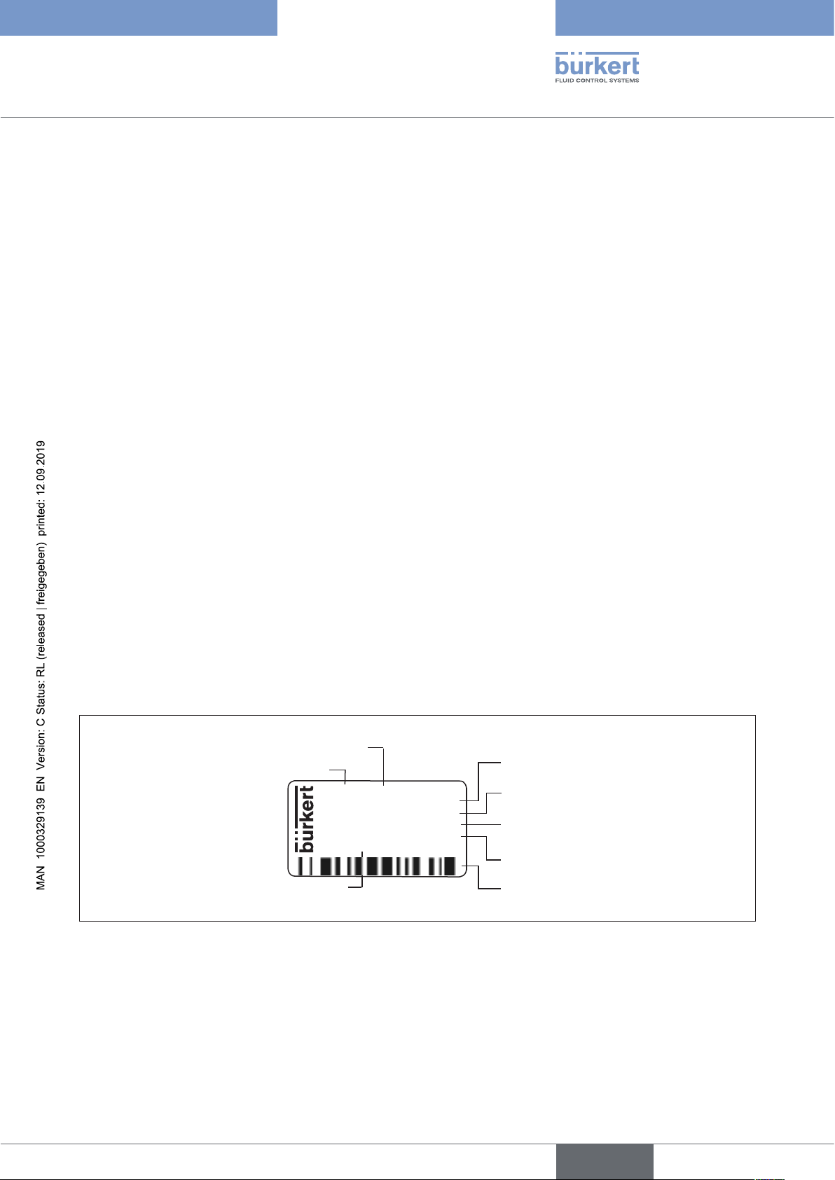
6.7.2 UL type label
Example:
Type; Features of the type code applicable to UL and ATEX
8694 -E3-...-0 PU02
Single act Pilot 3.0 24V
Pmax 7 bar
Tamb -10 - +55 °C
S/N 1001
00123456
D-74653 Ingelfingen
Figure 8: UL type label (example)
CE
W15MA
Type 8694
Technical data
Control function; pilot valve;
Supply voltage pilot valve
Max. operating pressure
Max. ambient temperature
Serial number; CE mark
Identification number; Date of manufacture (encoded)
Bar code
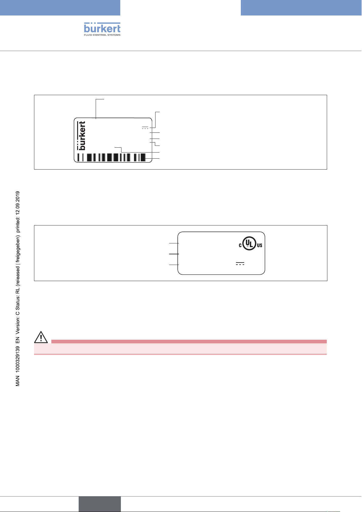
6.7.3 UL additional label
Example:
Degree of protection
Circuit with limited power
Supply voltage device
Figure 9: UL additional label (example)
Type 4X enclosure
NEC Class 2 only
Supply voltage: 24V
6.8 Electrical data
WARNING!
Only circuits with limited power may be used for UL approved components according to “NEC Class 2”.
6.8.1 Electrical data without bus control 24 V DC
22
Protection class 3 as per DIN EN 61140 (VDE 0140-1)
Connections Cable gland M16 x 1.5, wrench size 22 (clamping area 5 – 10 mm)
with screw-type terminals for cable cross-sections 0.14 – 1.5 mm²
Circular plug-in connector (M12 x 1, 8-pole)
Control valve
Operating voltage 24 V DC ± 10% - max. residual ripple 10 %
Power input ≤ 3.5 W
Input resistance
for set-point value signal 75 Ω at 0/4 - 20 mA / 12 bit resolution
english
Page 23
Type 8694
Technical data
Analogue position feedback
max. load
for current output 0/4 – 20 mA 560 Ω
Binary input 0 – 5 V = log “0”, 12 - 30 V = log “1”
inverted input in reverse order
Communications interface Direct connection to PC via USB adapter with integrated interface driver,
communication with communications software, see “Table 34: Accessories”.
6.8.2 Electrical data with AS-Interface bus control
Protection class 3 as per DIN EN 61140 (VDE 0140-1)
Connections Circular plug-in connector (M12 x 1, 4-pole)
Electrical supply voltage 29.5 V – 31.6 V DC (according to specification)
Devices without external supply voltage:
Max. power consumption 150 mA
Devices with external supply voltage:
External supply voltage 24 V ± 10 %
The power supply unit must
include a secure disconnection in
accordance with IEC 364-4-41
(PELV or SELV)
Max. power consumption 100 mA
Max. power consumption
from AS-Interface 50 mA
english
23
Page 24
6.9 Factory settings of the positioner
Functions can be activated via DIP switches:
Function Parameter Value
Type 8694
Technical data
CUTOFF
CHARACT
DIR.CMD
Table 4: Factory settings - Functions I
Sealing function below
Sealing function above
2 %
98 %
Select characteristic FREE
Effective direction set-point value rise
Functions can be activated via communications software:
Function Parameter Value
INPUT
DIR.ACTUATOR
SPLITRANGE
Function deactivated
X.LIMIT
Function deactivated
Set-point value input 4 ... 20 mA
Effective direction actual value rise
Signal split range below
Signal split range above
Stroke limit below
Stroke limit above
0 %
100 %
0 %
100 %
5)
24
X.TIME
Function deactivated
Actuating time Open
Actuating time Closed
(1 s) values determined by X.TUNE
(1 s) values determined by X.TUNE
After implementation of RESET: 1 s
X.CONTROL
Deadband
Open amplification factor
Close amplification factor
1,0 %
(1) values determined by X.TUNE
(1) values determined by X.TUNE
After implementation of RESET: 1
SAFE POSITION
SIGNAL ERROR
Safety position 0 %
Sensor break detection set-point value OFF
Function deactivated
BINARY INPUT
OUTPUT
(optional)
Table 5: Factory settings Functions II
5) Without change to the settings via the communications software a linear characteristic is stored in FREE.
Binary input function
Operating principle of binary input
Norm signal output: Parameter
Norm signal output: Type
Safety position
Normally open
Position
4 – 20 mA
english
Page 25
Type 8694
Control and display elements
7 CONTROL AND DISPLAY ELEMENTS
The following chapter describes the operating statuses as well as the control and display elements of the positioner.
Further information on the operation of the positioner can be found in the chapter entitled “12 Start-up”.
7.1 Operating status
AUTOMATIC (AUTO)
Normal controller mode is implemented and monitored in AUTOMATIC operating status.
→ LED 1 flashes green.
MANUAL
In MANUAL operating status the valve can be opened and closed manually via the keys.
→ LED 1 flashes red / green alternately.
DIP switch 4 can be used to switch between the two operating statuses AUTOMATIC and MANUAL.
ON DIP
2 3 4
1
7.2 Control and display elements of the positioner
Version 1
LED 2LED 1
Key 1
Key 2
LED 2
DIP Switches
Communications
interface
Version 2
Communications
interface
LED 1
ON DIP
1 2 3 4
Figure 10: Description of control elements
Key 1
Key 2
25
english
Page 26

Type 8694
Control and display elements
The positioner features 2 buttons, 4-pole DIP switches and 2x 2-colored LEDs as a display element.
NOTE!
Breakage of the pneumatic connection pieces due to rotational impact.
▶ When unscrewing and screwing in the body casing or transparent cap, do not hold the actuator of the pro-
cess valve but the connection housing.
→ To operate the buttons and DIP switches, for
Version 1: unscrew the body casing
Version 2: unscrew the transparent cap
Transparent cap
Body casing
Connection housing
Actuator
Version 1 Version 2
Figure 11: Open positioner
Body casing
Seal
body casing
Connection housing
Figure 12: Position of the seal in the body casing
→ Version 1:
Check that the seal is correctly positioned in the body casing.
26
NOTE!
Damage or malfunction due to penetration of dirt and humidity.
▶ To observe degree of protection IP65 / IP67, screw the transparent cap in all the way.
→ Close the device (assembly tool: 674077
6) The assembly tool (674077) is available from your Bürkert sales office.
english
6)
).
Page 27

Type 8694
Control and display elements
7.3 Configuration of the keys
The configuration of the 2 keys varies depending on the operating status (AUTOMATIC / MANUAL).
The description of the operating statuses (AUTOMATIC / MANUAL) can be found in the chapter entitled “7.1
Operating status”.
Version 1 Version 2
Key 1
Key 2
Figure 13: Description of the buttons
Key 1
Key 2
NOTE!
Breakage of the pneumatic connection pieces due to rotational impact.
▶ When unscrewing and screwing in the body casing or transparent cap, do not hold the actuator of the pro-
cess valve but the connection housing.
→ To operate the buttons, for
Version 1: unscrew the body casing
Version 2: unscrew the transparent cap
Transparent cap
Body casing
Connection housing
Actuator
Version 1 Version 2
Figure 14: Open positioner
27
english
Page 28

MANUAL operating status (DIP switch 4 set to ON):
Key Function
7)
1
2
Table 6: Configuration of the keys for MANUAL operating status
Aerate
(manually open / close the actuator)
Deaerate7)
(manually open / close the actuator)
8)
8)
AUTOMATIC operating status (DIP switch 4 set to OFF):
Key Function
1 Press for 5 seconds to start the X.TUNE function
2 -
Type 8694
Control and display elements
Table 7: Configuration of the keys for AUTOMATIC operating status
Body casing
Seal
body casing
Connection housing
Figure 15: Position of the seal in the body casing
→ Version 1:
Check that the seal is correctly positioned in the body casing.
NOTE!
Breakage of the pneumatic connection pieces due to rotational impact.
▶ When unscrewing and screwing in the body casing or transparent cap, do not hold the actuator of the pro-
cess valve but the connection housing.
28
Damage or malfunction due to penetration of dirt and humidity.
▶ To observe degree of protection IP65 / IP67, screw the transparent cap in all the way.
→ Close the device (assembly tool: 674077
7) No function if the binary input was activated with the “Manual/Auto change-over” via the communications software
8) Depending on the operating principle of the actuator.
9) The assembly tool (674077) is available from your Bürkert sales office.
9)
).
english
Page 29

Type 8694
Control and display elements
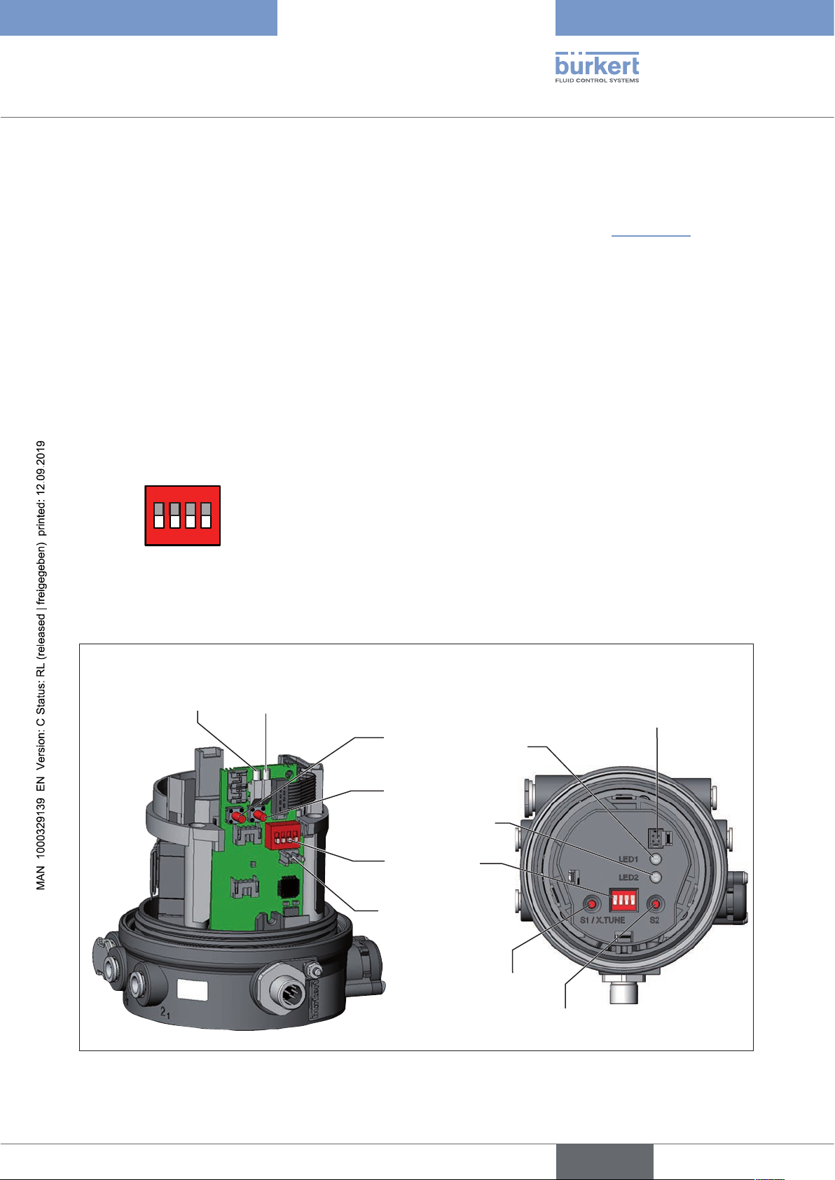
7.4 Function of the DIP switches
ON DIP
2 3 4
1
NOTE!
Breakage of the pneumatic connection pieces due to rotational impact.
▶ When unscrewing and screwing in the body casing or transparent cap, do not hold the actuator of the pro-
cess valve but the connection housing.
→ To operate the DIP switches, for
Version 1: unscrew the body casing
Version 2: unscrew the transparent cap
Transparent cap
Version 1 Version 2
Figure 16: Open positioner
DIP Switches Position Function
1 ON Reversal of the effective direction of the set-point value (DIR.CMD)
(set-point value 20 – 4 mA corresponds to position 0 – 100 %), descending
OFF Normal effective direction of the set-point value
(set-point value 4 – 20 mA corresponds to position 0 – 100 %), ascending
2 ON Sealing function active. The valve completely closes below 2 %
above 98 % of the set-point value (CUTOFF)
OFF No sealing function
3 ON Correction characteristic for adjustment of the operating characteristic
(linearization of the process characteristic CHARACT)
OFF Linear characteristic
Body casing
Connection housing
Actuator
11)
10)
and opens
4 ON Operating status MANUAL (BY HAND)
OFF Operating status AUTOMATIC (AUTO)
Table 8: DIP Switches
10) Factory setting, can be changed via communications software.
11) The characteristic type can be changed via communications software.
29
english
Page 30

Type 8694
Control and display elements
Information about the communications software:
The switching position of the DIP switch has priority over the settings via the communications software.
If the values of the sealing function (CUTOFF) or the correction characteristic (CHARACT) are changed
via the communications software, the corresponding function must be active (DIP switches set to ON).
The effective direction of the set-point value (DIR.CMD) can be changed via the DIP switches only.
If the correction characteristic (CHARACT) is not changed via the communications software, a linear characteristic is saved when DIP switch 3 is set to ON.
A detailed description of the functions can be found in the chapter entitled “Basic functions”.
Body casing
Seal
body casing
Connection housing
Figure 17: Position of the seal in the body casing
→ Version 1:
Check that the seal is correctly positioned in the body casing.
NOTE!
Breakage of the pneumatic connection pieces due to rotational impact.
▶ When unscrewing and screwing in the body casing or transparent cap, do not hold the actuator of the pro-
cess valve but the connection housing.
D
amage or malfunction due to penetration of dirt and humidity.
▶ To observe degree of protection IP65 / IP67, screw the transparent cap in all the way.
→ Close the device (assembly tool: 674077
12)
).
30
12) The assembly tool (674077) is available from your Bürkert sales office.
english
Page 31

Type 8694
Control and display elements
7.5 Display of the LEDs
Version 1 Version 2
LED 1 LED 2
LED 1
(green /
red)
Display of mode
statuses
AUTO, MANUAL,
X.TUNE and FAULT
LED 2
(green /
yellow)
Display of the actuator
status
(open, closed, opens
or closes)
Figure 18: LED display
LED 1 (green / red)
LED statuses
Display
green red
on off Acceleration phase when Power ON
flashes slowly off Operating status AUTO (AUTOMATIC)
flashing flashing MANUAL operating status
alternating
flashes quickly off X.TUNE function
off on
ERROR (see chapter entitled “7.6 Error messages”)
off flashes slowly AUTO operating status for sensor break detection
Table 9: Display LED 1
LED 2 (green / yellow)
LED statuses
Display
green yellow
on off Actuator closed
off on Actuator open
flashes slowly off
off flashes slowly
remaining control deviation
(actual value > set-point value)
remaining control deviation
(actual value < set-point value)
flashes quickly off Closing in MANUAL operating status
off flashes quickly Opening in MANUAL operating status
Table 10: Display LED 2
31
english
Page 32

Type 8694
Control and display elements
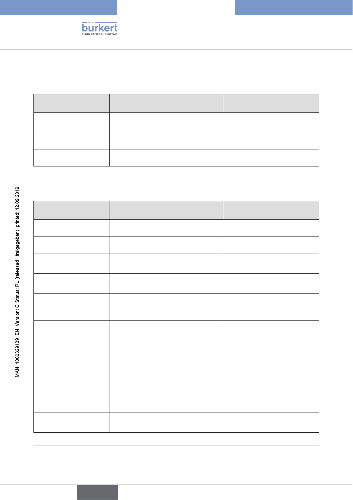
7.6 Error messages
7.6.1 Error messages in MANUAL and AUTOMATIC operating statuses
Display Cause of fault Remedial action
LED 1 (red) onChecksum error in data memory
→ Data memory defective
The device automatically switches to an older
→
(possibly not current) data record.
Table 11: Error messages in the operating statuses
Not possible, device defective
7.6.2 Error messages while the X.TUNE function is running
Display Cause of fault Remedial action
LED 1 (red) onNo compressed air connected Connect compressed air
Compressed air failure while the X.TUNE
function was running
Actuator or control system deaeration side
leaking
Control system aeration side leaking Not possible, device defective
Check compressed air supply
Not possible, device defective
32
Table 12: Error messages for the X.TUNE function
english
Page 33

Type 8694
Installation
8 INSTALLATION
8.1 Safety instructions
DANGER!
Risk of injury from high pressure in the equipment/device.
▶ Before working on equipment or device, switch off the pressure and deaerate/drain lines.
Risk of electric shock.
▶ Before working on equipment or device, switch off the power supply and secure to prevent reactivation.
▶ Observe applicable accident prevention and safety regulations for electrical equipment.
WARNING!
Risk of injury from improper installation.
▶ Installation may be carried out by authorized technicians only and with the appropriate tools.
Risk of injury from unintentional activation of the system and an uncontrolled restart.
▶ Secure system from unintentional activation.
▶ Following assembly, ensure a controlled restart.
8.2 Installation of the positioner Type 8694 on process valves of series 2103, 2300 and 2301
NOTE!
When mounting on process valves with a welded body, follow the installation instructions in the operating instructions for the process valve.
Procedure:
1. Install switch spindle
Transparent cap
Pilot air ports
(plug-in hose connectors with collets or
threaded bushings)
Actuator
Figure 19: Installation of the switch spindle (1), series 2103, 2300 and 2301
→ Unscrew the transparent cap on the actuator and unscrew the position display (yellow cap) on the spindle
extension (if present).
english
33
Page 34

Type 8694
Installation
→ For version with plug-in hose connector, remove the collets (white nozzles) from both pilot air ports (if
present).
Puck
Switch spindle
Guide element
Groove ring
max. 1 Nm
max. 5 Nm
Actuator cover
O-ring
Spindle extension
Figure 20: Installation of the switch spindle (2), series 2103, 2300 and 2301
NOTE!
Improper installation may damage the groove ring in the guide element.
The groove ring is already be pre-assembled in the guide element and must be “locked into position” in the
undercut.
▶ When installing the switch spindle, do not damage the groove ring.
→ Push the switch spindle through the guide element.
NOTE!
Screw locking paint may contaminate the groove ring.
▶ Do not apply any screw locking paint to the switch spindle.
→ To secure the switch spindle, apply some screw locking paint (Loctite 290) in the tapped bore of the spindle
extension in the actuator.
34
→ Check that the O-ring is correctly positioned.
→ Screw the guide element to the actuator cover (maximum torque: 5 Nm).
→ Screw switch spindle onto the spindle extension. To do this, there is a slot on the upper side
(maximum torque: 1 Nm).
→ Push puck onto the switch spindle and lock into position.
english
Page 35

Type 8694
Installation
2. Install sealing rings
→ Pull the form seal onto the actuator cover (smaller diameter points upwards).
→ Check that the O-rings are correctly positioned in the pilot air ports.
When the positioner is being installed, the collets of the pilot air ports must not be fitted to the actuator.
Form seal
Pilot air port
Caution:
collets must not be
fitted !
Installation of the form
seal
Figure 21: Installation of the sealing rings, series 2103, 2300 and 2301
3. Install positioner
→ Align the puck and the positioner until
1. the puck can be inserted into the guide rail of the positioner (see “Figure 22”)
and
2. the connection pieces of the positioner can be inserted into the pilot air ports of the actuator (see also
“Figure 23”).
NOTE!
Damaged printed circuit board or malfunction.
▶ Ensure that the puck is situated flat on the guide rail.
Guide rail
Puck
Figure 22: Aligning the puck
35
english
Page 36

Type 8694
Installation
→ Push the positioner, without turning it, onto the actuator until no gap is visible on the form seal.
NOTE!
Too high torque when screwing in the fastening screw does not ensure degree of protection IP65 /
IP67.
▶ The fastening screws may be tightened to a maximum torque of 1.5 Nm only.
→ Attach the positioner to the actuator using the two side fastening screws. In doing so, tighten the screws only
hand-tight (max. torque: 1.5 Nm).
Fastening screws
max. 1.5 Nm
Connection pieces
Pilot air
ports
Figure 23: Installation of positioner, series 2103, 2300 and 2301
Actuator
8.3 Installing the positioner Type 8694 on process valves belonging to series 26xx and 27xx
Procedure:
1. Install switch spindle
Guide element
Spindle extension
36
Actuator
Figure 24: Installing the switch spindle (1), series 26xx and 27xx
→ Unscrew the already fitted guide element from the actuator (if present).
→ Remove intermediate ring (if present).
english
Page 37

Type 8694
Installation
Puck
Switch spindle
Guide element
O-ring
Plastic part
(Switch spindle)
Spindle (actuator)
Figure 25: Installing the switch spindle (2), series 26xx and 27xx
→ Press the O-ring downwards into the cover of the actuator.
→ Actuator size 125 and bigger with high air flow rate:
remove existing spindle extension and replace with the new one. To do this, apply some screw locking paint
(Loctite 290) in the tapped bore of the spindle extension.
→ Screw the guide element into the cover of the actuator using a face wrench
13)
(torque: 8.0 Nm).
→ To secure the switch spindle, apply some screw locking paint (Loctite 290) to the thread of the switch spindle.
→ Screw the switch spindle onto the spindle extension. To do this, there is a slot on the upper side
(maximum torque: 1 Nm).
→ Push the puck onto the switch spindle until it engages.
13) Journal Ø: 3 mm; journal gap: 23.5 mm
37
english
Page 38

Type 8694
Installation
2. Install positioner
→ Push the positioner onto the actuator. The puck must be aligned in such a way that it is inserted into the guide
rail of the positioner.
NOTE!
Damaged printed circuit board or malfunction.
▶ Ensure that the puck is situated flat on the guide rail.
Guide rail
Puck
Figure 26: Aligning the puck
→ Press the positioner all the way down as far as the actuator and turn it into the required position.
Fastening screws
max. 1.5 Nm
Figure 27: Installing the positioner
Ensure that the pneumatic connections of the positioner and those of the valve actuator are situated preferably vertically one above the other.
If they are positioned differently, longer hoses may be required other than those supplied in the accessory kit.
38
NOTE!
Too high torque when screwing in the fastening screw does not ensure degree of protection IP65 /
IP67.
▶ The fastening screws may be tightened to a maximum torque of 1.5 Nm only.
→ Attach the positioner to the actuator using the two side fastening screws. In doing so, tighten the fastening
screws hand-tight only (maximum torque: 1.5 Nm).
english
Page 39

Type 8694
Installation
3. Install pneumatic connection between positioner and actuator
Pilot air outlet 2
Pilot air outlet 2
1
2
Upper pilot air port
Lower pilot air port
Example ∅ 80, CFA
Figure 28: Installing the positioner
→ Screw the plug-in hose connectors onto the positioner and the actuator.
→ Using the hoses supplied in the accessory kit, make the pneumatic connection between the positioner and
actuator with the following “Table 13: Pneumatic connection to actuator - CFA” or “Table 14: Pneumatic connection to actuator - CFB”.
NOTE!
Damage or malfunction due to ingress of dirt and moisture.
To observe degree of protection IP65 / IP67:
▶ In the case of actuator size ∅ 80, ∅ 100
connect the pilot air outlet which is not required to the free pilot air port of the actuator or seal with a plug.
▶ In the case of actuator size ∅ 125
seal the pilot air outlet 22 which is not required with a plug and feed the free pilot air port of the actuator via a
hose into a dry environment.
Control function A (CFA)
Process valve closed in rest position (by spring force)
Actuator size ∅ 80, ∅ 100
∅ 125
Pilot air outlet
2
2
2
2
2
2
1
1
Positioner
Upper pilot air port
Lower pilot air port
Actuator
Dry area
Table 13: Pneumatic connection to actuator - CFA
39
english
Page 40

Control function B (CFB)
Process valve open in rest position (by spring force)
Actuator size ∅ 80, ∅ 100
Pilot air outlet
2
2
2
1
Positioner
Upper pilot air port
Lower pilot air port
Actuator
Dry area
Table 14: Pneumatic connection to actuator - CFB
Type 8694
Installation
2
∅ 125
2
2
1
"In rest position" means that the pilot valves of the positioner Type 8694 are isolated or not actuated.
8.4 Rotating the actuator module
The actuator module (positioner and actuator) can be rotated for straight seat valves and angle seat valves
belonging to series 2300, 2301 and 27xx only.
The position of the connections can be aligned steplessly by rotating the actuator module (positioner and actuator)
through 360°.
Process valves Type 2300, 2301 and 27xx: Only the entire actuator module can be rotated. The positioner cannot be rotated contrary to the actuator.
The process valve must be in the open position for alignment of the actuator module.
DANGER!
Risk of injury from high pressure in the equipment/device.
▶ Before working on equipment or device, switch off the pressure and deaerate/drain lines.
Procedure:
40
→ Clamp valve body in a holding device (only required if the process valve has not yet been installed).
NOTE!
Damage to the seat seal or the seat contour.
▶ When removing the actuator module, ensure that the valve is in open position.
→ Control function A: Open process valve.
english
Page 41

Type 8694
Installation
Actuator
module
Key contour
Nipple
Figure 29: Rotating the actuator module
without hexagon
Hexagon
Nipple
with hexagon
→ Using a suitable open-end wrench, counter the wrench flat on the pipe.
→ Actuator module without hexagon:
Fit special key
14)
exactly in the key contour on the underside of the actuator.
→ Actuator module with hexagon:
Place suitable open-end wrench on the hexagon of the actuator.
WARNING!
Risk of injury from discharge of medium and pressure.
If the direction of rotation is wrong, the body interface may become detached.
▶ Rotate the actuator module in the specified direction only (see “Figure 30”) .
→ Actuator module without hexagon:
Rotate clockwise (as seen from below) to bring the actuator module into the required position.
→ Actuator module with hexagon:
Rotate counter-clockwise (as seen from below) to bring the actuator module into the required position.
Open-end wrench
Special key
Figure 30: Rotating with special key / open-end wrench
14) The special key (665702) is available from your Bürkert sales office.
without hexagonwith hexagon
41
english
Page 42

Type 8694
Installation
8.5 Rotating the positioner for process valves belonging to series 26xx and 27xx
If the connecting cables or hoses cannot be fitted properly following installation of the process valve, the positioner
can be rotated contrary to the actuator.
Fastening screw (2x)
Positioner
Pneumatic connection
Actuator
Figure 31: Rotating the positioner, series 26xx and 27xx
Procedure
→ Loosen the pneumatic connection between the positioner and the actuator.
→ Loosen the fastening screws (hexagon socket wrench size 2.5).
→ Rotate the positioner into the required position.
NOTE!
Too high torque when screwing in the fastening screw does not ensure degree of protection IP65 /
IP67.
▶ The fastening screw may be tightened to a maximum torque of 1.5 Nm only.
→ Tighten the fastening screws hand-tight only (maximum torque: 1.5 Nm).
→ Re-attach the pneumatic connections between the positioner and the actuator. If required, use longer hoses.
42
english
Page 43

Type 8694
Pneumatic installation
9 PNEUMATIC INSTALLATION
DANGER!
Risk of injury from high pressure in the equipment/device.
▶ Before working on equipment or device, switch off the pressure and deaerate/drain lines.
WARNING!
Risk of injury from improper installation.
▶ Installation may be carried out by authorized technicians only and with the appropriate tools.
Risk of injury from unintentional activation of the system and an uncontrolled restart.
▶ Secure system from unintentional activation.
▶ Following installation, ensure a controlled restart.
Procedure:
→ Connect the control medium to the pilot air port (1) (3 – 7 bar; instrument air, free of oil, water and dust).
→ Attach the exhaust air line or a silencer to the exhaust air port (3)
and, if available to the exhaust air port (3.1)
Important information for the problem-free functioning of the device:
▶ The installation must not cause back pressure to build up.
▶ Select a hose for the connection with an adequate cross-section.
▶ The exhaust air line must be designed in such a way that no water or other liquid can get into the device
through the exhaust air port (3) or (3.1).
Exhaust air port
Figure 32: Pneumatic connection
(label: 3)
Pilot air port
(label: 1)
Additional exhaust air port (label: 3.1)
only for Type 23xx and 2103
with pilot-operated control system
for high air flow rate (actuator size ø 130)
43
english
Page 44

Type 8694
Pneumatic installation
Caution:(Exhaust air concept):
In compliance with degree of protection IP67, an exhaust air line must be installed in the dry area.
Keep the adjacent supply pressure always at least 0.5 – 1 bar above the pressure which is required to
move the actuator to its end position. This ensures that the control behavior is not extremely negatively
affected in the upper stroke range on account of too little pressure difference.
During operation keep the fluctuations of the pressure supply as low as possible (max. ±10 %). If fluctuations are greater, the control parameters measured with the X.TUNE function are not optimum.
9.1 Manual actuation of the actuator via pilot valves
9.1.1 Single-acting actuators (control function A and B)
The actuator can be moved without a power supply from the rest position to its end position and back again. To do
this, the pilot valves must be actuated with a screwdriver.
NOTE!
The hand lever may be damaged if it is simultaneously pressed and turned.
▶ Do not press the hand lever when turning it.
Pilot valve non activated
(normal position)
Hand lever
to the left
Pilot valve activated
Hand lever
to the right
Pilot valve
for aerate
Pilot valve
for deaerate
Type 8694 for high air flow rate
Pilot valve
for aerate
44
Pilot valve
for deaerate
Figure 33: Pilot valves for aerate and deaerate the actuator
english
Page 45

Type 8694
Pneumatic installation
Move actuator to end position
Turn the hand levers to the right using a screwdriver.
Note: - do not press the hand levers when turning them
- observe the sequence as described below
→ 1. Actuate hand lever pilot valve deaeration.
→ 2. Actuate hand lever pilot valve aeration.
Both hand levers point to the right.
The actuator moves to the end position.
Figure 34: Move actuator to end position
Move actuator back to the rest position
Turn the hand levers to the left using a screwdriver.
Note: - do not press the hand levers when turning them
- observe the sequence as described below
2.1.
Type 8694 for high air flow rate
1.2.
→ 1. Actuate hand lever pilot valve aeration.
→ 2. Actuate hand lever pilot valve deaeration.
Both hand levers point to the left (normal position).
The actuator moves by spring force to the rest position.
Figure 35: Move actuator back to the rest position
Caution:
If the pilot valves are actuated, electrical control is not possible.
▶ Move hand levers to normal position before starting up the device.
1.2.
Type 8694 for high air flow rate
2.1.
45
english
Page 46

Type 8694
Electrical installation 24 V DC
10 ELECTRICAL INSTALLATION 24 V DC
All electrical inputs and outputs of the device are not galvanically isolated from the supply voltage.
Two kinds of connections are used for the electrical bonding of the positioner:
• Cable gland
with cable gland M16 x 1.5 and screw-type terminals
• Multi-pole
with circular plug-in connector M12 x 1, 8-pole
10.1 Safety instructions
DANGER!
Risk of electric shock.
▶ Before working on equipment or device, switch off the power supply and secure to prevent reactivation.
▶ Observe applicable accident prevention and safety regulations for electrical equipment.
WARNING!
Risk of injury from improper installation.
▶ Installation may be carried out by authorized technicians only and with the appropriate tools.
Risk of injury from unintentional activation of the system and an uncontrolled restart.
▶ Secure system from unintentional activation.
▶ Following installation, ensure a controlled restart.
10.2 Electrical installation with circular plug-in connector
DANGER!
Risk of electric shock.
▶ Before working on equipment or device, switch off the power supply and secure to prevent reactivation.
▶ Observe applicable accident prevention and safety regulations for electrical equipment.
46
10.2.1 Designation of the contacts Type 8694
View without body
casing
7
8
Figure 36: Circular plug M12 x 1, 8-pole
english
5
6
1
Circular plug
4
M12 x1, 8-pole
3
2
Page 47

Type 8694
Electrical installation 24 V DC
10.2.2 Connection of the positioner Type 8694
→ Connect the pins according to the model (options) of the positioner.
Input signals of the control center (e.g. PLC) - circular plug M12 x 1, 8-pole
Pin Wire color
1 2white
brown
grey
5
pink
6
Table 15: Pin assignment - input signals of the control center - circular plug M12 x 1, 8-pole
15)
Configuration External circuit / signal level
Set-point value + (0/4 – 20 mA)
Set-point value GND
Binary input +
Binary input GND
1
+ (0/4 ... 20 mA)
2 GND
5 + 0 ... 5 V (log. 0)
identical to Pin 3 (GND)
Output signals to the control center (e.g. PLC) - circular plug M 12 x 1, 8-pole
(required for analogue output option only)
Pin Wire color
8 7red
blue
Table 16: Pin assignment - output signals of the control center - circular plug M12 x 1, 8-pole
15)
Configuration External circuit / signal level
Analogue position feedback +
Analogue position feedback GND
8
7 GND
+ (0/4 ... 20 mA)
10 ... 30 V (log. 1)
Operating voltage (circular plug M12 x 1, 8-pole)
Pin Wire color
4 3yellow
15)
Configuration External circuit
+ 24 V
4
24 V DC ± 10 %
green
Table 17: Pin assignment - operating voltage (circular plug M12 x 1, 8-pole)
GND
3
max. residual ripple 10 %
When the supply voltage is applied, the positioner is operating.
→ Make the required basic settings and actuate the automatic adjustment of the positioner, as described in the
chapter entitled “12 Start-up”.
15) The indicated colors refer to the connecting cable available as an accessory (919061)
47
english
Page 48

Type 8694
Electrical installation 24 V DC
10.3 Electrical installation with cable gland
DANGER!
Risk of electric shock.
▶ Before working on equipment or device, switch off the power supply and secure to prevent reactivation.
▶ Observe applicable accident prevention and safety regulations for electrical equipment.
NOTE!
Breakage of the pneumatic connection pieces due to rotational impact.
▶ When unscrewing and screwing in the body casing, do not hold the actuator of the process valve but the
connection housing.
→ The screw-type terminals can be accessed by unscrewing the body casing (stainless steel).
Figure 37: Open positioner
→ Push the cables through the cable gland.
Transparent cap
Body casing
Connection housing
Actuator
48
english
Page 49

Type 8694
Electrical installation 24 V DC
Figure 38: Connection of screw-type terminals
→ Connect the positioner according to the following tables:
1
16)
2
16)
3
4
5
6
7
Input signals from the control centre (e.g. PLC)
Terminal Configuration External circuit
4
5
1
Table 18: Assignment of screw-type terminals - input signals of the control center - cable gland
Set-point value +
Set-point value GND
Binary input +
4
5 GND
1 + 0 ... 5 V (log. 0)
with reference to terminal 7 (GND)
+ (0/4 ... 20 mA)
Output signals to the control center (e.g. PLC; for analog output option only)
Terminal Configuration External circuit
2
Analogue position feedback +
2
+ (0/4 ... 20 mA)
3
Table 19: Assignment of screw-type terminals - output signals to the control center - cable gland
Analogue position feedback GND
3 GND
10 ... 30 V (log. 1)
Operating voltage
Terminal Configuration External circuit
6
7
Table 20: Assignment of screw-type terminals - operating voltage - cable gland
16) Option only
Operating voltage +
Operating voltage GND
6
7
24 V DC ± 10 %
max. residual ripple 10 %
49
english
Page 50

Body casing
Seal
body casing
Connection housing
Figure 39: Position of the seal in the body casing
→ Check that the seal is correctly positioned in the body casing.
NOTE!
Breakage of the pneumatic connection pieces due to rotational impact.
Type 8694
Electrical installation 24 V DC
▶ When unscrewing and screwing in the body casing, do not hold the actuator of the process valve but the
connection housing.
Damage or malfunction due to penetration of dirt and humidity.
To ensure degree of protection IP65 / IP67:
▶ Tighten the union nut on the cable gland according to the cable size or dummy plugs used (approx. 1.5 Nm).
▶ Screw the body casing in all the way.
→ Tighten union nut on the cable gland (torque approx. 1.5 Nm).
→ Close the device (assembly tool: 674077
When the power supply is applied, the positioner is operating.
17)
).
→ Make the required basic settings and actuate the automatic adjustment of the positioner, as described in the
chapter entitled “12 Start-up”.
50
17) The assembly tool (674077) is available from your Bürkert sales office.
english
Page 51

Type 8694
AS-Interface installation
11 AS-INTERFACE INSTALLATION
11.1 AS-Interface connection
AS-Interface (Actuator Sensor Interface) is a field bus system which is used primarily for networking binary sensors
and actuators (slaves) with a higher-level control (master).
Bus line
Unshielded two-wire line (AS-Interface line as AS-Interface flat cable) along which both information (data) and
energy (power supply for the actuators and sensors) are transmitted.
Network topology
Freely selectable within wide limits, i.e. star, tree and line networks are possible. Further details are described in the
AS-Interface specification (A/B slave model conforms to the version 3.0 specification).
11.2 Maximum length of the bus line
The bus line may have a maximum length of 100 m. During the design phase, consider all AS-Interface lines in an
AS-Interface section, i.e. even the stub lines to the individual slaves.
The development stage which is actually possible depends on the sum of all the individual operating currents per
positioner which are supplied on a common AS-Interface bus segment via the bus.
• Observe the maximum power supply ≤ 8 A via certified AS-Interface power supply units. Details see
AS-Interface specification.
• Note the optional model “AS-Interface with external power supply” to relieve the AS-Interface bus
segment (see “11.7.2”).
• Use cables according to the AS-Interface specification. If other cables are used, the maximum bus line
length will change.
11.3 Technical data for AS-Interface PCBs
Version Profile S-7.3.4 Version Profile S-7.A.5
Supply via AS-Interface via AS-Interface
Outputs 16 bit set-point value 16 bit set-point value
Inputs - 16 bit feedback
Certification Certificate no. 87301 after version 3.0 Certificate no. xxxxx after version 3.0
Table 21: Technical data
english
51
Page 52

Type 8694
AS-Interface installation
11.4 Programming data
Version Profile S-7.3.4 Version Profile S-7.A.5
I/O configuration 7 hex 7 hex
ID code 3 hex (analog profile) A hex
Extended ID code 1
Extended ID code 2 4 hex 5 hex
Profile S-7.3.4 S-7.A.5
Table 22: Programming data
Bit configuration
1. Output set-point value (Value range 0 – 10.000, is equivalent to 0 – 100 %)
2. Input feedback
18)
(Value range 0 – 10.000 (16 Bit, signed integer), is equivalent to 0 – 100 %)
Values below 0 (0.0 %) and above 10,000 (100.0 %) are possible due to mechanical tolerances.
Example: Position -1.0 % corresponds to -100 = 0xFF9C
F hex
(Default value, can be changed by the user)
7 hex
Byte 2 Byte 1
D15 D14 D13 D12 D11 D10 D9 D8 D7 D6 D5 D4 D3 D2 D1 D0
Parameter bit P3 P2 P1 P0
Output not used not used not used not used
Table 23: Bit configuration
52
english
Page 53

Type 8694
AS-Interface installation
11.5 Communication sequence for the version S-7.A.5 profile
1. Following start-up, the AS-Interface master (from master class 4) automatically replaces the ID object with the
S-7.A.5 slave.
Master transmits 3 bytes:
1. Byte: Code = 16 dez
2. Byte: Index = 0 dez
3. Byte: Length = 5 dez
2. Then the following cyclical commands can be used:
Code = 0 (get cyclic data from Slave)
→ for feedback 0 – 100 %
S-7.A.5 slave replies with 6 bytes
1. Byte: Code = 80 dez
2. Byte: Vendor ID (high)
3. Byte: Vendor ID (low)
4. Byte: Device ID (high)
5. Byte: Device ID (low)
6. Byte: 1 word output +
or with 2 Byte (Read Response not OK)
1. Byte: Code = 144 dez
2. Byte: Error Code = 0
1 word input
= 120 dez
= 1 dez
= 34 dez
dez (no error)
1
dez (illegal index)
2
dez (illegal length)
3
dez (request not
implemented)
4
dez (busy)
Code = 1 (put cyclic data to slave)
→ for set-point value 0 – 100 %
18) Only for version with S-7.A.5 profile
53
english
Page 54

Type 8694
AS-Interface installation
11.6 LED status display
NOTE!
Breakage of the pneumatic connection pieces due to rotational impact.
▶ When unscrewing and screwing in the body casing, do not hold the actuator of the process valve but the
connection housing.
The LED status display indicates the bus status (LED green and red).
Bus LED green
Bus LED red
Figure 40: LED status display AS-Interface
LED green LED red
off off POWER OFF
off on No data traffic (expired Watch Dog at slave address does not equal 0)
on off OK
flashing on Slave address equals 0
off flashing Electronic error or external reset
flashing flashing Timeout bus communication after 100 ms (periphery error)
Table 24: LED Status Display AS-Interface
Body casing
54
Seal
body casing
Connection housing
Figure 41: Position of the seal in the body casing
english
Page 55

Type 8694
AS-Interface installation
→ Check that the seal is correctly positioned in the body casing.
NOTE!
Breakage of the pneumatic connection pieces due to rotational impact.
▶ When unscrewing and screwing in the body casing, do not hold the actuator of the process valve but the
connection housing.
D
amage or malfunction due to penetration of dirt and humidity.
▶ To observe degree of protection IP65 / IP67, screw the transparent cap in all the way.
→ Close the device (assembly tool: 674077
19) The assembly tool (674077) is available from your Bürkert sales office.
19)
).
11.7 Electrical installation AS-interface
11.7.1 Safety instructions
DANGER!
Risk of electric shock.
▶ Before working on equipment or device, switch off the power supply and secure to prevent reactivation.
▶ Observe applicable accident prevention and safety regulations for electrical equipment.
WARNING!
Risk of injury from improper installation.
▶ Installation may be carried out by authorized technicians only and with the appropriate tools.
Risk of injury from unintentional activation of the system and an uncontrolled restart.
▶ Secure system from unintentional activation.
▶ Following installation, ensure a controlled restart.
english
55
Page 56

Type 8694
AS-Interface installation
11.7.2 Connection with circular plug-in connector M12 x 1, 4-pole, male
It is not necessary to open the positioner for the multi-pole model.
Bus connection without external / with external supply voltage
Pin Designation Configuration
1 Bus + AS-Interface bus line +
2 NC or GND (optional) not used or external supply voltage – (optional)
3 Bus – AS-Interface bus line 4 NC or 24 V + (optional) not used or external supply voltage + (optional)
Table 25: Pin assignment of circular plug-in connector for AS-Interface
Views of plug: From the front onto the pins, the soldered connections are behind
Pin 4:
Pin 3:
Pin 4:
Pin 3:
NC
Pin 1:
Bus +
Figure 42: Bus connection without external supply
voltage
Bus –
Pin 2:
NC
24 V +
Pin 1:
Bus +
Figure 43: Bus connection with external supply
voltage (optional)
Bus –
Pin 2:
GND
When the supply voltage is applied, the positioner is operating.
→ Make the required basic settings and actuate the automatic adjustment of the positioner, as described in the
chapter entitled “12 Start-up”.
11.7.3 Connection with multi-pole cable and ribbon cable terminal
As an alternative to the bus connection model with 4-pole circular plug, there is the positioner with multi-pole cable
(M12 circular plug) and ribbon cable terminal. The wiring diagram of the circular plug corresponds to the bus connection of the M12 4-pole circular plug (see “Figure 42” and “Figure 43”) and can easily be connected to the ribbon
cable terminal (see “Figure 45”).
56
Figure 44: Positioner 8694 with multi-pole cable and ribbon cable terminal
english
Page 57

Type 8694
AS-Interface installation
Calculated bus line length:
When designing the system, consider the length of the cable which is fed directly to the positioner for the
maximum bus line length (multi-pole cable and cable inside: 1.0 m).
Example calculation:
When using 62 positioner with multi-pole cable, the AS-Interface flat cable may still be maximum 38 m long.
100 m – 62 x 1.0 m = 38 m
If the calculated bus line length of 100 m is exceeded, a commercially available AS-Interface repeater can be
used.
Handling the ribbon cable terminal
The multi-pole cable features a ribbon cable terminal - with M12 plug-in connector branch circuit - for AS-Interface
flat cable. The ribbon cable terminal contacts the AS-Interface flat cable by means of penetration technology which
allows installation by "clipping in" the AS-Interface flat cable without cutting and without removing insulation.
Work steps:
→ Open the ribbon cable terminal
(loosen screws and remove cover)
→ Insert flat cable conclusively
→ Close ribbon cable terminal again
→ Tighten screws
Screws
M12 plug-in con-
Figure 45: Ribbon cable terminal
When the supply voltage is applied, the positioner is operating.
nector branch circuit
Slightly undo thread-forming screws
(approx. 3/4 turn to the left) and position them on the
existing tapped bore and screw in.
→ Make the required basic settings and actuate the automatic adjustment of the positioner, as described in the
chapter entitled “12 Start-up”.
english
57
Page 58

Type 8694
Start-up
12 START-UP
12.1 Safety instructions
DANGER!
Risk of injury from high pressure in the equipment/device.
▶ Before working on equipment or device, switch off the pressure and deaerate/drain lines.
WARNING!
Risk of injury from improper operation.
Improper operation may result in injuries as well as damage to the device and the area around it.
▶ Before start-up, ensure that the operating personnel are familiar with and completely understand the contents
of the operating instructions.
▶ Observe the safety instructions and intended use.
▶ Only adequately trained personnel may operate the equipment/the device.
12.2 Specifying the standard settings
The basic settings of the positioner are implemented at the factory.
To adjust the positioner to local conditions, the X.TUNE function must be run following installation.
12.2.1 Running the automatic adjustment X.TUNE
WARNING!
Danger due to the valve position changing when the X.TUNE function is running.
When the X.TUNE is running under operating pressure, there is an acute risk of injury.
▶ Never run X.TUNE while a process is running.
▶ Take appropriate measures to prevent the equipment from being accidentally actuated.
NOTE!
Avoid maladjustment of the controller due to an incorrect pilot pressure or applied operating medium
pressure.
58
▶ Run X.TUNE whenever the pilot pressure (= pneumatic auxiliary energy) is available during subsequent operation.
▶ Run the X.TUNE function preferably without operating medium pressure to exclude interference caused by
flow forces.
To run X.TUNE, the positioner must be in the AUTOMATIC operating status (DIP switch 4 = OFF).
english
Page 59

Type 8694
Start-up
NOTE!
Breakage of the pneumatic connection pieces due to rotational impact.
▶ When unscrewing and screwing in the body casing or transparent cap, do not hold the actuator of the pro-
cess valve but the connection housing.
→ To operate the DIP switches, for
Version 1: unscrew the body casing
Version 2: unscrew the transparent cap
Transparent cap
Body casing
Connection housing
Actuator
Version 1 Version 2
Figure 46: Open positioner
Version 1
Figure 47: Automatic adjustment X.TUNE
→ Start the X.TUNE by pressing button 1
20)
for 5 s.
LED 1
LED 2
LED 1
Key 2
Key 1
LED 2
DIP Switches
Communications
interface
Key 1
Key 2
Communications interface
Version 2
ON DIP
1 2 3 4
While the X.TUNE is running, LED 1 flashes quickly (green).
When the automatic adjustment is complete, LED 1 flashes slowly (green)
21)
.
The changes are automatically transferred to the memory (EEPROM) provided the X.TUNE function is successful.
Important: When the X.TUNE function is activated, the actuator cannot be actuated via the AS-Interface
communication.
20) The X.TUNE can also be started via communications software.
21) If a fault occurs, LED 1 is lit red.
english
59
Page 60

Type 8694
Start-up
Body casing
Seal
body casing
Connection housing
Figure 48: Position of the seal in the body casing
→ Version 1: Check that the seal is correctly positioned in the body casing.
NOTE!
Breakage of the pneumatic connection pieces due to rotational impact.
▶ When unscrewing and screwing in the body casing or transparent cap, do not hold the actuator of the pro-
cess valve but the connection housing.
D
amage or malfunction due to penetration of dirt and humidity.
▶ To observe degree of protection IP65 / IP67, screw the transparent cap in all the way.
→ Close the device (assembly tool: 674077
22)
).
60
22) The assembly tool (674077) is available from your Bürkert sales office.
english
Page 61

Type 8694
Operation and function
13 OPERATION AND FUNCTION
The positioner type 8694 has different basic and additional functions which can be configured and parameterized
via the DIP switches or the communications software.
13.1 Basic functions
The following basic functions can be activated via the DIP switches (CUTOFF and CHARACT) or changed
(DIR.CMD).
Function Description DIP Switches OFF ON
DIR.CMD
CUTOFF
CHARACT
Table 26: Basic functions of DIP switches
The following basic function can be changed via the communications software only.
Function Description Factory setting
INPUT
RESET
X.TUNE
Table 27: Basic function of communications software
Effective direction between input
signal and set-point position
Sealing function for position
controller
Selection of the Transfer Characteristic between Input Signal and
Stroke (Correction Characteristic)
Entry of the standard signal input
for the set-point value
Reset to factory settings
Automatic adjustment of the positioner to the relevant operating
conditions
1 rise fall
2 Sealing function off Sealing function on
3 Linear characteristic Correction
4 – 20 mA
characteristic
The INPUT, CUTOFF and CHARACT functions can be parameterized via the communications software.
english
61
Page 62

Type 8694
Operation and function
13.1.1 DIR.CMD - Effective direction of the positioner set-point value
You can use this function to adjust the effective direction between the input signal (INPUT) and the nominal
position of the actuator.
Factory setting: DIP switch set to OFF (ascending)
DIP Switches Position Function
1 ON Reversal of the effective direction of the set-point value (DIR.CMD)
(set-point value 20 – 4 mA corresponds to position 0 – 100 %), fall
OFF Normal effective direction of the set-point value
(set-point value 4 – 20 mA corresponds to position 0 – 100 %),
rise
Table 28: DIP switch 1
The effective direction (DIR.CMD) can only be changed via DIP switch 1 in the positioner.
Nominal position
rise
fall
Input signal
(INPUT)
Figure 49: DIR.CMD graph
62
english
Page 63

Type 8694
Operation and function
13.1.2 CUTOFF - Sealing function for the positioner
This function causes the valve to be sealed outside the control range.
Control mode resumes at a hysteresis of 1%.
Factory setting: DIP switch 2 set to OFF (no sealing function)
DIP Switches Position Function
2 ON Sealing function active. The valve completely closes below 2 %
23)
and opens above 98 % of the set-point value (CUTOFF)
OFF No sealing function
Table 29: DIP switch 2
The communications software can be used to change the limits for the position set-point value as a percentage.
The switching position of the DIP switches in the positioner has priority over the communications
software, i.e. settings of the sealing function (CUTOFF) which are modified via the communications
software are only active if DIP switch 2 in the positioner is set to ON.
Valve stroke [%]
Adjustable from 75 – 100 %
Figure 50: CUTOFF graph
23) Factory setting can be changed via communications software.
Adjustable from 0 – 25 %
Set-point
value [%]
63
english
Page 64

Type 8694
Operation and function
13.1.3 CHARACT - Select the transfer characteristic between input signal (position set-point value) and stroke
Characteristic (customer-specific characteristic)
This function can be used to activate a transfer characteristic with respect to set-point value (set-point position)
and valve stroke for correction of the flow-rate or operating characteristic.
The transfer characteristic can be changed via the communications software only.
Factory setting: DIP switch 3 set to OFF (linear)
DIP Switches Position Function
3 ON Correction characteristic for adjustment of the operating characteristic
(linearization of the process characteristic CHARACT)
OFF Linear characteristic
Table 30: DIP switch 3
The switching position of the DIP switches in the positioner has priority over the communications
software, i.e. settings of the correction characteristic (CHARACT) which are modified via the communications software are only active if DIP switch 3 in the positioner is set to ON.
Characteristics which can be selected via the communications software:
Characteristic Description
linear Linear characteristic
1 : 25 Equal percentage characteristic 1 : 25
1 : 33 Equal percentage characteristic 1 : 33
1 : 50 Equal percentage characteristic 1 : 50
25 : 1 Inversely equal percentage characteristic 25 : 1
24)
64
33 : 1 Inversely equal percentage characteristic 33 : 1
55 : 1 Inversely equal percentage characteristic 55 : 1
FREE User-defined characteristic, freely programmable via nodes
Table 31: Selection of characteristics
24) The characteristic type can be changed via the communications software only.
english
Page 65

Type 8694
Operation and function
The flow characteristic kV = f(s) indicates the flow-rate of a valve, expressed by the value kV as a function of the
stroke s of the actuator spindle. It is determined by the design of the valve seat and the seat seal. In general two
types of flow characteristics are implemented, the linear and the equal percentage.
In the case of linear characteristics, equal k
= n
(dk
⋅ ds).
V
lin
In the case of an equal percentage characteristic, an equal percentage change of the k
value changes dkV are assigned to equal stroke changes ds.
V
value corresponds to a
V
stroke change ds.
(dk
V/kV
= n
eqlprct
⋅ ds).
The operating characteristic Q = f(s) specifies the correlation between the volumetric flow Q in the installed
valve and the stroke s. This characteristic has the properties of the pipelines, pumps and consumers. It therefore
exhibits a form which differs from the flow characteristic.
Standardized valve stroke [%]
Position set-point value
[%]
Figure 51: Characteristic
In the case of control tasks for closed-loop control systems it is usually particular demands which are placed on the
course of the operating characteristic, e.g. linearity. For this reason it is occasionally necessary to correct the course
of the operating characteristic in a suitable way. For this purpose the positioner features a transfer element which
implements different characteristics. These are used to correct the operating characteristic.
Equal percentage characteristics 1:25, 1:33, 1:50, 25:1, 33:1, and 50:1 as well as a linear characteristic can be
set. A characteristic can be freely programmed using nodes.
english
65
Page 66

Type 8694
Operation and function
Entering the freely programmable characteristic
The characteristic is defined by 21 nodes distributed uniformly over the position set-point values ranging from 0 –
100%. They are spaced at intervals of 5%. A freely selectable stroke (adjustment range 0 – 100%) is assigned to
each node. The difference between the stroke values of two adjacent nodes must not be greater than 20%.
Example of a programmed characteristic
Valve stroke [&]
100
90
80
70
60
50
40
30
20
10
0
10 20 30 40 50 60 70 80 90 100
4 – 20 mA
0 – 20 mA
Figure 52: Example of a programmed characteristic
13.1.4 INPUT - Enter the input signal
Unit signal [%]
66
Under this menu option, enter the unit signal used for the set-point value.
Factory setting: 4 – 20 mA
english
Page 67

Type 8694
Operation and function
13.1.5 RESET - Reset to factory settings
This function can be used to reset the positioner to the factory settings.
13.1.6 X.TUNE - Automatic adjustment of the positioner to the relevant operating conditions
The X.TUNE function must be run for a function check of the positioner to adjust to specific local features.
WARNING!
While the X.TUNE function is running, the valve automatically moves from its current position.
▶ Never run X.TUNE while a process is running.
▶ Take appropriate measures to prevent the system / positioner from being unintentionally actuated.
NOTE!
Avoid maladjustment of the controller due to an incorrect compressed air supply or applied operating
medium pressure.
▶ Run X.TUNE whenever the compressed air supply (= pneumatic auxiliary energy) is available during subse-
quent operation.
▶ Run the X.TUNE function preferably without operating medium pressure to exclude interference caused by
flow forces.
To run X.TUNE, the positioner must be in the AUTOMATIC operating state (DIP switch 4 = OFF).
→ Set up TUNE / TUNE Functions.
→ Start X.TUNE. To do this, click „Start X.TUNE“
The progress of X.TUNE is shown in the communication software:
When the automatic adjustment completes, a message appears.
2)
.
The changes are automatically transferred to the positioner‘s memory (EEPROM) after the X.TUNE function is
successful.
english
67
Page 68

Type 8694
Operation and function
13.2 Auxiliary functions
The following additional functions can be configured and parameterized via the communications software:
Function Description
DIR.ACTUATOR
SPLITRANGE
X.LIMIT
X.TIME
X.CONTROL
SAFE POSITION
SIGNAL ERROR
BINARY INPUT
OUTPUT
Table 32: Auxiliary functions
Assignment of the aeration status of the actuator chamber to the actual position
Signal split range; input signal as a % for which the valve runs through the entire
stroke range.
Limit the mechanical stroke range
Limit the control speed
Parameterize the position controller
Input the safety position
Configuration of signal level fault detection
Activation of the binary input
Configuration of the outputs (only with auxiliary board for analogue feedback signal
or binary outputs)
13.2.1 DIR.ACTUATOR - Effective direction of the actuator
68
Use this function to set the effective direction between the aeration state of the actuator and the actual position.
Factory setting: rise
Rise: Direct effective direction (deaerated → 0 %; aerated 100 %)
Case: Inverse effective direction (deaerated → 100 %; aerated 0 %)
Actual
position
increasing
deaerated
Figure 53: DIR.ACTUATOR graph
aerated
decreasing
Aeration
state
english
Page 69

Type 8694
Operation and function
13.2.2 SPLITRANGE - Signal split range
Minimum and maximum values of the input signal as a % for which the valve runs through the entire stroke range.
Factory setting: Lower signal range split = 0 %; Upper signal range split = 100 %
Lower value split range: Input the minimum value of the input signal as a %
Adjustment range: 0 – 75 %
Upper value split range: Input the maximum value of the input signal as a %
Adjustment range: 25 – 100 %
Use this function to limit the position set-point value range of the positioner by specifying a minimum and a
maximum value. This makes it possible to divide a unit signal range that is used (4 – 20 mA, 0 – 20 mA) into
several positioners (without or with overlapping). This allows several valves to be used alternately or, in the case
of overlapping set-point value ranges, simultaneously as actuators.
To split a unit signal range into two set-point value ranges:
Valve stroke [%]
Set-point value range
Positioner 1
Figure 54: SPLTRNG graph
Set-point value range
Positioner 2
Set-point value [mA]
(INPUT)
english
69
Page 70

Type 8694
Operation and function
13.2.3 X.LIMIT - Limiting the mechanical stroke range
This function limits the (physical) stroke to specified % values (lower and upper). In doing so, the stroke range of
the limited stroke is set equal to 100 %. If the limited stroke range is left during operation, negative actual positions or actual positions greater than 100 % are shown.
Factory setting: Lower position limit = 0 %, upper position limit = 100 %
Adjustment ranges:
Lower position limit: 0 – 50 % of the entire stroke
Upper position limit: 50 – 100 % of the entire stroke
The minimum distance between the upper and lower stroke limit is 50 %. Therefore if one value is entered with a
minimum distance of < 50 % the other value is adjusted automatically.
Limited
stroke (%)
Control range in
AUTOMATIC mode
Adjustment range in MANUAL mode
Figure 55: X.LIMIT graph
Physical
stroke (%)
Unlimited
stroke
Limited
stroke
Set-point value
[mA] (INPUT)
70
english
Page 71

Type 8694
Operation and function
13.2.4 X.TIME -
Limiting the control speed
Use this function to specify the opening and closing times for the entire stroke and thereby limit control speeds.
When the X.TUNE function is running, the minimum opening and closing time for the entire stroke is automatically entered for Open and Close. Therefore, movement can be at maximum speed.
Factory setting: values determined at the factory by the X.TUNE function
If the control speed will be limited, values can be input for Open and Close which are between the minimum
values determined by the X.TUNE and 60 seconds.
Valve timeopen
Valve timeclose: Closing time for entire stroke (in seconds)
Effect of limiting the opening speed when there is a jump in the set-point value
: Opening time for entire stroke (in seconds)
Adjustment range: 1 – 60 seconds
Adjustment range: 1 – 60 seconds
Valve stroke [%]
Set-point
value
Actual value
t
Open
Figure 56: X.TIME graph
71
english
Page 72

Type 8694
Operation and function
13.2.5 X.CONTROL - Parameterization of the positioner
Use this function to set the parameters for the positioner (dead band and amplification factors (kp)).
Deadband: Insensitivity range of the positioner
Entry for the deadband as a % in reference to the scaled stroke range;
i.e. X.LIMIT upper stroke limit - X.LIMIT lower stroke (see auxiliary function X.LIMIT).
This function causes the controller to respond only beginning at a specific control difference. This function saves
wear on the solenoid valves in the positioner and the pneumatic actuator.
If the auxiliary function X.CONTROL is in the main menu while X.TUNE (Autotune of the positioner) is
running, the deadband is determined automatically depending on the friction behavior of the actuator drive.
The value determined in this way is an approximate value. You can re-adjust it manually.
Xd1‘
Position setpoint value
Figure 57: X.CONTROL graph
Open/close amplification factor: Parameters for the positioner
Open amplification factor: Amplification factor of the positioner (for closing the valve)
Close amplification factor: Amplification factor of the positioner (for opening the valve)
Control
difference
Xd1
Position
actual value
Dead band
Xd1
to the
controller
Xd1‘
13.2.6 SAFE POSITION - Definition of the safe position
This function specifies the actuator safety position which is approached at defined signals.
72
The set safety position is only approached if there is a corresponding signal at the binary input (for configuration see BINARY INPUT) or if a signal error occurs (for configuration see SIGNAL ERROR).
If the mechanical stroke range is limited with the X.LIMIT function, only safety positions within these limits
can be approached.
This function is executed in AUTOMATIC mode only.
english
Page 73

Type 8694
Operation and function
13.2.7 SIGNAL ERROR - Configuration of signal level fault detection
The SIGNAL ERROR function is used to detect a fault on the input signal.
Fault detection
Fault detection can be selected for a 4 – 20 mA signal only:
Fault if input signal ≤ 3.5 mA (± 0.5 % of final value, hysteresis 0.5 % of final value)
If 0 – 20 mA is selected, sensor break detection cannot be selected.
A signal error is indicated on the device by the red LED for “setpoint error detection” ON.
Safety position for sensor break ON:
The following configurations can occur with “safety position if setpoint error” ON:
Active SAFE POSITION
If a fault is detected, the drive moves to the lower SAFE POSITION set position.
Inactive SAFE POSITION
If a fault is detected, the drive moves to the end position which it would assume in the isolated state.
13.2.8 BINARY INPUT - Activation of the binary input
This function activates the binary input.
The following settings can be implemented for this:
• Approach the safety position
• Switching over the MANUAL/AUTOMATIC operating mode
• Starting the function X.TUNE (standard valid since software version A.20, with rotary actuator valid since
software version A.02).
Safety position
Approach the safety position.
Active SAFE POSITION function
the drive moves to the lower SAFE POSITION set position.
Inactive SAFE POSITION
The drive moves to the end position which it would assume in the isolated state.
Switch over the operating state to MANUAL or AUTOMATIC.
Binary input = 0 → AUTOMATIC operating state
Binary input = 1 → MANUAL operating state
If switching over the operating mode is selected, you can no longer switch the operating mode with DIP switch 4
Starting the function X.TUNE
Binary input = 1 → Starting X.TUNE.
english
73
Page 74

Type 8694
Operation and function
13.2.9 OUTPUT (optional) - Configuration of the analog output
The OUTPUT menu item only appears in the selection of auxiliary functions if the positioner has an analog output
(optional) or if no parameters have been read in yet.
The analog output can be used for feedback of the current position or of the set-point value to the control center.
Standard signal output: parameter Position Output of the current position
Set-point value Output of the set-point value
Standard signal output: type 4 – 20 mA Selection of the unit signal
0 – 20 mA
74
english
Page 75

Type 8694
Safety end positions
14 SAFETY END POSITIONS
14.1 Safety end positions after failure of the electrical or pneumatic auxiliary power
Safety end positions after failure of the auxiliary
Actuator system Designation
single-acting
up
down
Control
function A
electrical pneumatic
down
power
pilot-controlled control
system:
down
direct-acting control
system:
not defined
up
down
Table 33: Safety end positions
single-acting
Control
function B
pilot-controlled control
system:
up
up
direct-acting control
system:
not defined
english
75
Page 76

Type 8694
Maintenance
15 MAINTENANCE
15.1 Safety instructions
DANGER!
Risk of injury from high pressure in the equipment/device.
▶ Before working on equipment or device, switch off the pressure and deaerate/drain lines.
Risk of electric shock.
▶ Before working on equipment or device, switch off the power supply and secure to prevent reactivation.
▶ Observe applicable accident prevention and safety regulations for electrical equipment.
WARNING!
Risk of injury from improper maintenance.
▶ Maintenance may be performed by authorised technicians only.
Risk of injury from unintentional activation of the system and an uncontrolled restart.
▶ Secure system from unintentional activation.
▶ Following maintenance, ensure a controlled restart.
76
english
Page 77

Type 8694
Maintenance
15.2 Service at the air intake filter
DANGER!
Risk of injury from high pressure in the equipment/device.
▶ Before working on equipment or device, switch off the pressure and deaerate/drain lines.
To protect the internal solenoid valves and the actuator, the pilot air is filtered.
The direction of flow of the air intake filter in installed state is from the inside to the outside through the filter
material.
Quick connector
O-ring
Air intake filter
Figure 58: Service on the air intake filter
Procedure:
→ Unlock the quick connector by pressing the holding element and pulling out the air intake filter (if necessary,
use a suitable tool in between the recesses in the head of the filter).
→ Clean the filter or, if necessary, replace the filter.
→ Check inner O-ring and, if required, clean.
→ Insert the air intake filter all the way into the quick connector.
DANGER!
Risk of injury due to improper installation.
▶ Ensure that the air intake filter is installed correctly.
→ Check that the air intake filter is secure.
77
english
Page 78

Type 8694
Accessories
16 ACCESSORIES
Designation Order no.
USB adapter for connection to a PC in conjunction with an extension cable 227093
Communicator
Connection cable M12 x 1, 8-pole 919061
Assembly tool 647077
Table 34: Accessories
16.1 Communications software
The PC operating program “Communicator” is designed for communication with the devices from the Bürkert positioner family (valid since serial number 20000).
Information at www.burkert.com
A detailed description and precise schedule of the procedure for the installation and operation of the
software can be found in the associated documentation.
16.1.1 USB interface
The PC requires an USB interface for communication with the positioners as well as an additional adapter with
interface driver (see “Table 34: Accessories”).
The data transfer must be according to HART specification.
16.1.2 Download
Download the software at: www.burkert.com
78
english
Page 79

Type 8694
Disassembly
17 DISASSEMBLY
17.1 Safety instructions
DANGER!
Risk of injury from high pressure in the equipment/device.
▶ Before working on equipment or device, switch off the pressure and deaerate/drain lines.
Risk of electric shock.
▶ Before working on equipment or device, switch off the power supply and secure to prevent reactivation.
▶ Observe applicable accident prevention and safety regulations for electrical equipment.
WARNING!
Risk of injury from improper disassembly.
▶ Disassembly may be carried out by authorized technicians only and with the appropriate tools.
Risk of injury from unintentional activation of the system and an uncontrolled restart.
▶ Secure system from unintentional activation.
▶ Following disassembly, ensure a controlled restart.
17.2 Disassembly the positioner
Procedure:
1. Pneumatic connection
DANGER!
Risk of injury from high pressure in the equipment/device.
▶ Before working on equipment or device, switch off the pressure and deaerate/drain lines.
→ Loosen the pneumatic connection.
→ Series 20xx:
Loosen the pneumatic connection between positioner and actuator.
79
english
Page 80

Type 8694
Disassembly
2. Electrical connection
DANGER!
Risk of electric shock.
▶ Before working on equipment or device, switch off the power supply and secure to prevent reactivation.
▶ Observe applicable accident prevention and safety regulations for electrical equipment.
Circular plug-in connector:
→ Loosen the circular plug-in connector.
Cable gland:
→ Open the positioner: unscrewing the body casing in an anticlockwise direction.
→ Unscrew the screw terminals and pull out cables.
→ Close the positioner.
3. Mechanical connection
→ Loosen the fastening screws.
→ Remove the positioner upwards.
Pneumatic
connections
Positioner
Actuator
Electrical con-
nection cir-
cular plug-in
connector
Fastening
screws (2x)
Pneumatic
connection to
the actuator
80
Series 21xx
Figure 59: Disassembly the positioner
english
Actuator
Series 20xx
Page 81

Type 8694
Packaging and transport
18 PACKAGING AND TRANSPORT
NOTE!
Transport damages.
Inadequately protected equipment may be damaged during transport.
▶ During transportation protect the device against wet and dirt in shock-resistant packaging.
▶ Avoid the effects of heat and cold which could result in temperatures above or below the permitted storage
temperature.
19 STORAGE
NOTE!
Incorrect storage may damage the device.
▶ Store the device in a dry and dust-free location.
▶ Storage temperature -20 – +65°C.
20 DISPOSAL
→ Dispose of the device and packaging in an environmentally friendly manner.
NOTE!
Damage to the environment caused by device components contaminated with media.
▶ Observe the relevant disposal and environmental protection regulations.
Observe national waste disposal regulations.
english
81
Page 82

Type 8694
82
english
Page 83

www.burkert.com
 Loading...