

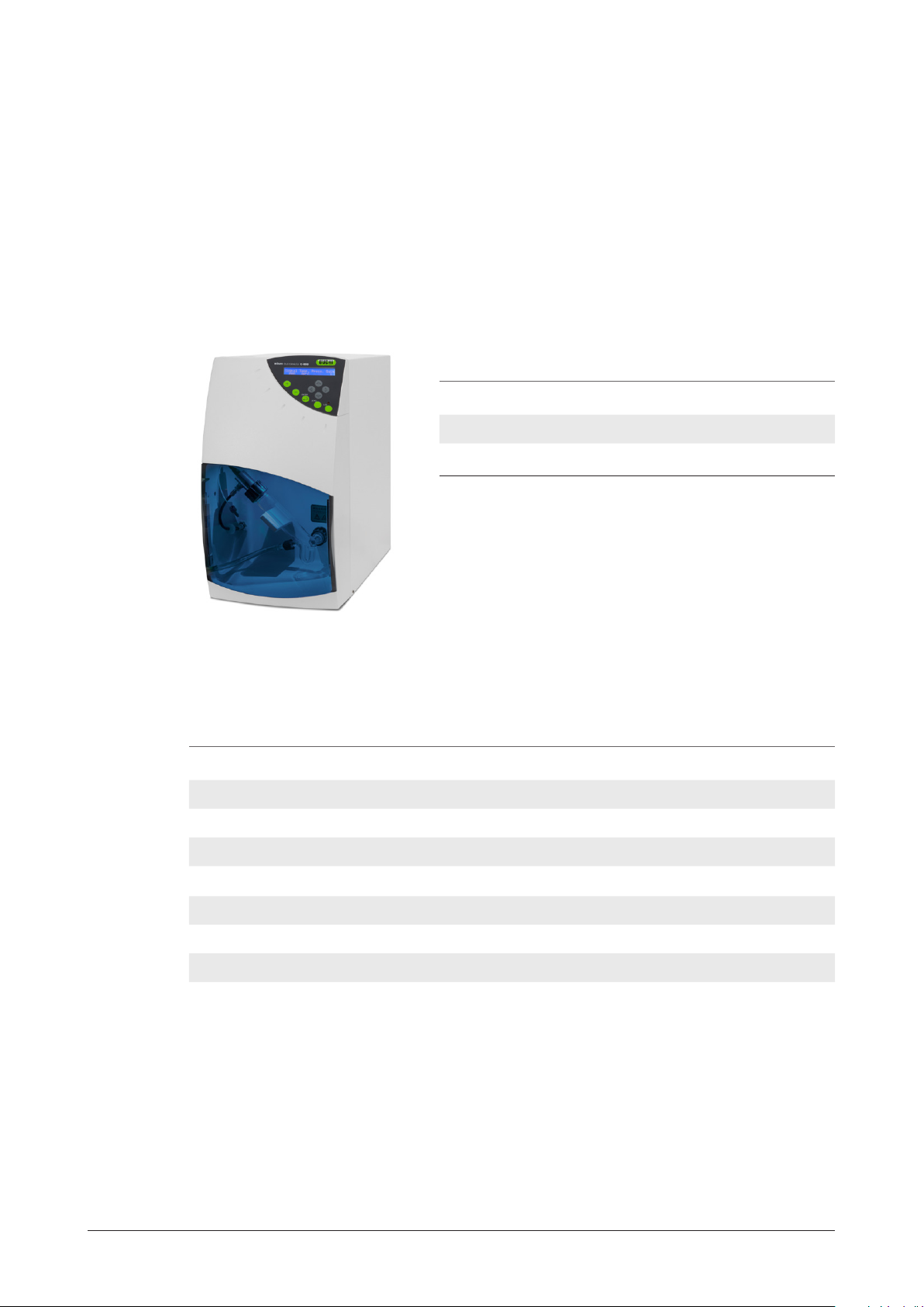
Page 1
ELS Detector C-650
Operation Manual
11593555 en
Page 2

Page 3

Table of content
1 About this manual 5
1.1 Abbreviations 5
2 Safety 6
2.1 User qualification 6
2.2 Proper use 6
2.3 Improper use 6
2.4 Safety warnings and safety signs 7
2.5 Product safety 9
2.5.1 General hazards 9
2.5.2 Warning labels on housing and assemblies 10
2.5.3 Personal protective equipment 10
2.6 General safety rules 10
2.6.1 Responsibility of the operator 10
2.6.2 Duty of maintenance and care 10
2.6.3 Spare parts to be used 10
2.6.4 Modifications 10
3 Technical data 11
3.1 Scope of delivery 11
3.1.1 Standard device 11
3.1.2 Standard accessories 11
3.1.3 Optional accessories 12
3.2 Technical data overview 12
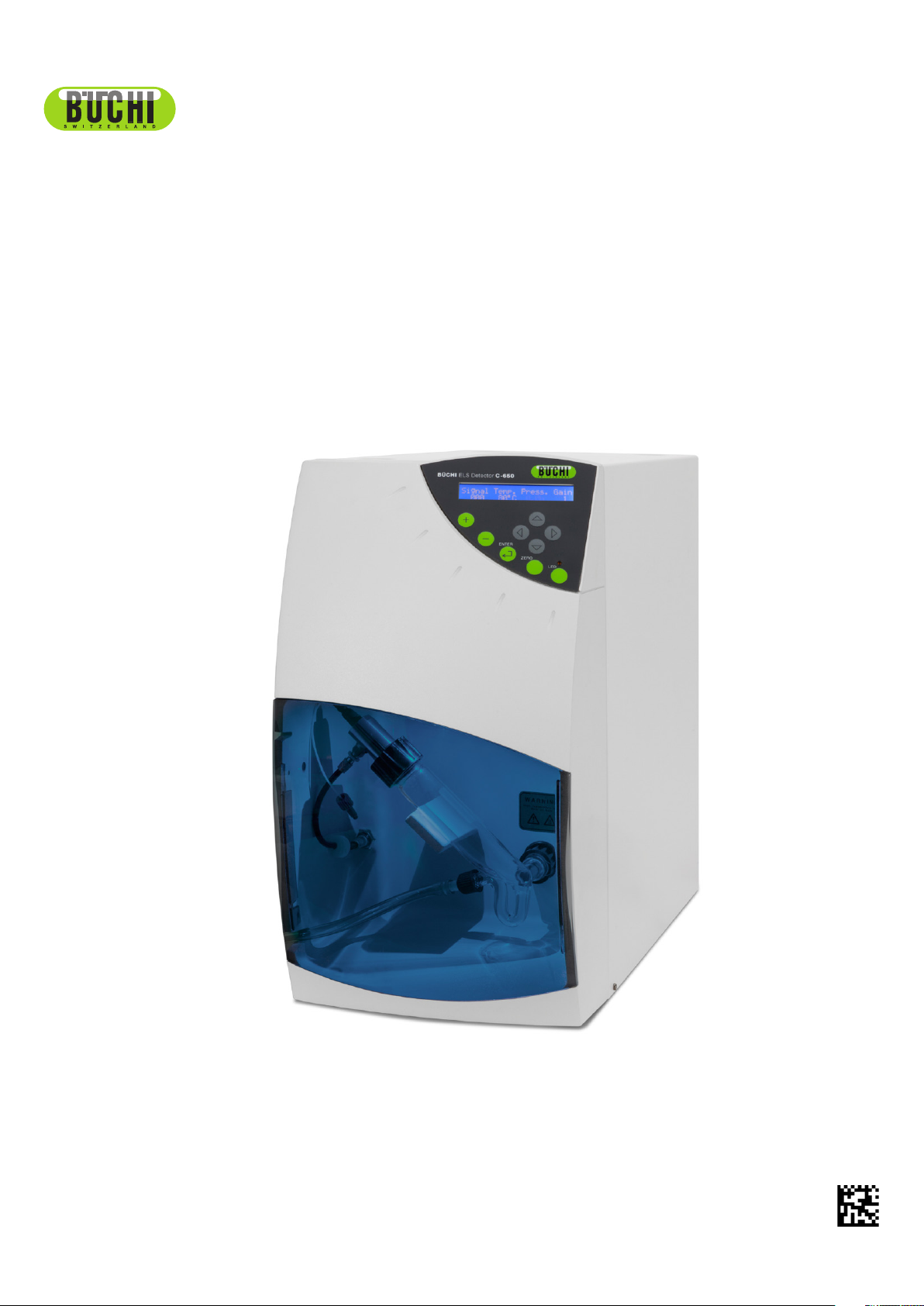
4 Description of function 13
4.1 Overview over the device 13
4.2 Functional principle 14
4.2.1 Nebulization 14
4.2.2 Evaporation of the solvent 16
4.2.3 Detection 16
4.3 Eluent flow splitting 17
5 Putting into operation 18
5.1 Installation site 18
5.2 Electrical connections 19
5.3 Gas supply 20
5.4 Exhaust venting and drain requirements 22
5.5 Installing the nebulizer/glass chamber assembly 23
5.5.1 Connecting the siphon overflow 24
5.5.2 Connecting the nebulization gas to the nebulizer 24
5.6 Installing the flow splitter 25
5.6.1 Connecting the flow splitter 25
5.6.2 Adjusting the flow rate of the ELSD splitter 25
5.6.3 Connecting to the ELS nebulizer 26
5.7 Powering up the device 26
Page 4

5.8 Control panel 26
5.8.1 Digital display 26
5.8.2 User interface 27
5.9 Initial test procedures 34
5.9.1 Preliminary activities 34
5.9.2 Electronic noise test 35
5.9.3 Background noise (stray light) test 35
5.9.4 Solvent noise test 36
5.9.5 Column noise test 37
6 Operation 38
6.1 Preparing the device for operation 38
6.2 Auto-zeroing the detector 38
6.2.1 Manual 38
6.2.2 External 39
6.3 Routine operation of the detector 39
6.4 Optimizing the performance 39
6.4.1 Selecting the optimum temperature 39
6.4.2 Optimizing the mobile phase 40
6.4.3 Sample pretreatment 41
6.4.4 Column treatment 41
6.4.5 Optimizing the noise filter 42
6.5 Powering down and shutting down the detector 42
7 Maintenance 43
7.1 Customer service 44
8 Troubleshooting 45
8.1 General troubleshooting information 45
8.2 Initial troubleshooting activities 45
8.3 Perform the noise test 46
8.4 Specific detector troubleshooting 46
8.5 Nebulizer cleaning and replacement procedures 47
8.6 Gas flow problems 49
8.7 Cleaning and decontamination 49
8.7.1 Device cleaning 49
8.7.2 Device decontamination 50
8.8 Light source exchange 50
9 Shutdown, storage, transport and disposal 51
9.1 Preparing the device for storage and transport 51
9.2 Storage and transport 51
10 Spare parts 52
11 Declarations and requirements 53
11.1 FCC requirements (for USA and Canada) 53
11.2 Declaration of conformity 54
Page 5

1 About this manual
This manual describes the Low Temperature Evaporative Light Scattering Detector C-650 and
provides all information required for its safe operation and to maintain it in good working order. It
is addressed to laboratory personnel and operators in particular.
Read this manual carefully before installing and running your system and note the safety precautions in chapter 2 in particular. Store the manual in the immediate vicinity of the device, so that it
can be consulted at any time.
No technical modifications may be made to the device without the prior written agreement of
BUCHI. Unauthorized modifications may affect the system safety or result in accidents. Technical
data are subject to change without notice.
NOTE
The symbols pertaining to safety are explained in chapter 2.
This manual is copyright. Information from it may not be reproduced, distributed or used for
competitive purposes, nor made available to third parties. The manufacture of any component
with the aid of this manual without prior written agreement is also prohibited.
The English manual is the original language Version Bnd serves as basis for all translations into
other languages. If you need another language version of this manual, you can download available versions at www.buchi.com.
1.1 Abbreviations
ELSD: Evaporative Light Scattering Detector
Fig: Figure
TTL: Time to live (electrical signal)
5
1 About this manual
C-650 Operation Manual, Version B
Page 6
2 Safety
This chapter points out the safety concept of the device and contains general rules of behavior
and warnings from hazards concerning the use of the product.
The safety of users and personnel can only be ensured if these safety instructions and the safety
related warnings in the individual chapters are strictly observed and followed. Therefore, the
manual must always be available to all persons performing the tasks described herein.
2.1 User qualification
The device may only be used by laboratory personnel and other persons who on account of
training or professional experience have an overview of the dangers which can develop when
operating the device.
Personnel without this training or persons who are currently being trained require careful instruction. The present Operation Manual serves as the basis for this.
2.2 Proper use
The device has been designed and built for the use in laboratories. The ELSDC-650 is a standalone device. The C-650 is designed to detect compounds in the eluent from Preparative Chromatography.
2.3 Improper use
Applications not mentioned above are improper. Also applications which do not comply with the
technical data are considered improper.
DANGER
During any improper use, the effectiveness of the protection systems can be affected.
• Avoid any improper use of the devices!
The operator bears the sole risk for any damages caused by such improper use.
The following uses are expressly forbidden:
• Use of the device in rooms which require ex-protected devices.
• Use on samples which can explode or inflame (e.g.: explosives, etc.) due to shock, friction,
heat or spark formation.
6
2 Safety
C-650 Operation Manual, Version B
Page 7
2.4 Safety warnings and safety signs
DANGER, WARNING, CAUTION and NOTICE are standardized signal words for identifying
levels of hazard seriousness of risks related to personal injury and property damage. All signal
words, which are related to personal injury are accompanied by the general safety sign.
For your safety it is important to read and fully understand the table below with the different signal words and their definitions!
Sign Signal word Definition Risk level
Indicates a hazardous situation which, if
DANGER
WARNING
CAUTION
not avoided, will result in death or serious
injury.
Indicates a hazardous situation which, if not
avoided, could result in death or serious
injury.
Indicates a hazardous situation which, if
not avoided, may result in minor or moderate injury.
★★★★
★★★☆
★★☆☆
Space for
supplementary safety
information
symbols.
★☆☆☆
(property damage
no
NOTICE
Indicates possible property damage, but no
practices related to personal injury.
only)
Supplementary safety information symbols may be placed in a rectangular panel on the left to
the signal word and the supplementary text (see example below).
Source of hazard.
Table of supplementary safety information symbols
The reference list below incorporates all safety information symbols used in this manual and their
meaning.
Symbol Meaning
SIGNAL WORD
• List of measures to avoid the herein described, hazard or hazardous situation.
• …
• …
General warning
Electrical hazard
Heavy weight, avoid overexertion
7
2 Safety
C-650 Operation Manual, Version B
Page 8

Symbol Meaning
Harmful to life-forms
Pinch point. Mechanical hazard.
Fire hazard
Hot item, hot surface
Device damage
Inhalation of substances
Chemical burns by corrosives
Wear laboratory coat
Wear protective goggles
Wear protective gloves
Heavy weight, lifting requires more than one person
8
2 Safety
C-650 Operation Manual, Version B
Page 9

Additional user information
Paragraphs starting with NOTE transport helpful information for working with the device/software
or its supplementaries. NOTEs are not related to any kind of hazard or damage (see following
example).
NOTE
Useful tips for the easy operation of the device/software.
2.5 Product safety
The ELSD is designed and built in accordance with state-of-the-art technology. Nevertheless,
risks to users, property, and the environment can arise when the device is used carelessly or
improperly.
The manufacturer has determined residual dangers emanating from the device
• if the device is operated by insufficiently trained personnel.
• if the device is not operated according to its proper use.
Appropriate warnings in this manual serve to make the user alert to these residual dangers.
2.5.1 General hazards
Pay attention to the following safety notices:
DANGER
Death or serious injuries by use in explosive environments.
• Do not store or operate the device in explosive environments.
• Provide sufficient ventilation and make sure to directly withdraw fumes
WARNING
Death or serious burns by flammable vapors, flames and sparks.
• Remove all sources of flammable vapors, flames and sparks
• Do not store flammable chemicals in the vicinity of the device
NOTICE
Risk of device damage by liquids or mechanical shocks.
• Do not spill liquids over the device or its components
• Do not move the device when it is loaded with sample liquid
• Do not drop the device or its components
• Keep external vibrations away from the device
• Safely attach the device to the bench in earthquake prone regions
• Do not operate the device without the safety shield installed
9
2 Safety
NOTICE
Risk of device damage by wrong mains supply.
• External mains supply must meet the voltage given on the type plate
• Check for sufficient grounding
C-650 Operation Manual, Version B
Page 10
2.5.2 Warning labels on housing and assemblies
The following warning sticker(s) can be found on the housing or assemblies of the C-650:
Symbol
Meaning Location
Hot item, hot surface Sticker / label, located at the heating block
2.5.3 Personal protective equipment
Always wear personal protective equipment such as protective eye goggles, protective clothing
and gloves. The personal protective equipment must meet all requirements of the supplementary
data sheets for the chemicals used.
WARNING
Serious chemical burns by corrosives.
• Observe supplementary data sheets of all used chemicals.
• Always wear protective goggles.
• Always wear protective gloves.
• Always wear protective clothes.
2.6 General safety rules
2.6.1 Responsibility of the operator
The head of laboratory is responsible for training his personnel.
The operator shall inform the manufacturer without delay of any safety-related incidents which
might occur during operation of the device. Legal regulations, such as local, state and federal
laws applying to the device must be strictly followed.
2.6.2 Duty of maintenance and care
The operator is responsible for ensuring that the device is operated in proper condition only, and
that maintenance, service, and repair jobs are performed with care and on schedule, and by
authorized personnel only.
2.6.3 Spare parts to be used
Use only genuine consumables and genuine spare parts for maintenance to assure good system
performance and reliability. Any modifications to the spare parts used are only allowed with the
prior written permission of the manufacturer.
2.6.4 Modifications
10
Modifications to the device are only permitted after prior consultation with and with the written
approval of the manufacturer. Modifications and upgrades shall only be carried out by an authorized BUCHI technical engineer. The manufacturer will decline any claim resulting from unauthorized modifications.
2 Safety
C-650 Operation Manual, Version B
Page 11
3 Technical data
This chapter introduces the device specifications. It contains the scope of delivery, technical
data, requirements and performance data.
3.1 Scope of delivery
Check the scope of delivery according to the order number.
NOTE
For detailed information on the listed products, see www.buchi.com or contact your local dealer.
3.1.1 Standard device
Table 3.1: Standard device
Product Order number
ELS Detector C-650 (230V/50 Hz) 11059105
ELS Detector C-650 (115V/60 Hz) 11059106
3.1.2 Standard accessories
Table 3.2: Standard accessories
Product Order number
C-650 signal cable 11059100
C-650 autozero cable 110 5 916 5
C-650 external signal cable 110 5 92 29
C-650 RS232 cable 110 59 2 75
Gas tubing, 6 mm, 2 m + 1 m 110 5 9 276
Set of fuses (115V) 110 5 9172
Set of fuses (230V) 110 5 9173
11
3 Technical data
C-650 Operation Manual, Version B
Page 12

3.1.3 Optional accessories
Table 3.3: Optional accessories
Product Order number
Flow splitter 110 5 9 0 07
3.2 Technical data overview
Table 3:4: Technical data
Dimensions (L×H×D) 250×450×550 mm
Connection voltage 115VAC (±10%)/60Hz/1.8A
Weight 18.5 kg
Overvoltage category II
Pollution degree 2
230VAC (±10%)/50Hz/1.7A
Environmental conditions
Temperature
Altitude
Humidity
For indoor use only
5–40 °C
Up to 2000m above sea level
Maximum relative humidity 80% for temperatures up to
31°C, and then linearly decreasing to 50% at 40°C
Detection High sensitivity photomultiplier
Light source Selected high efficiency blue LED
Temperature range Ambient to 100°C
Gas flow control Manual and computer controlled (power down) nebulization
gas flow and patented auxiliary gas flow
Gas consumption Less than 5l/min
Eluent flow rate 0.1mL/min to 5mL/min
Device control Microprocessor with stand alone manual keypad or PC
control
Operating parameters control Liquid crystal digital panel
Signal drift Less than 2mV/30min
Signal output 0–1V (analog), RS-232 (digital)
12
Inputs Remote Autozero (contact closure and TTL)
Remote Power down Mode (contact closure and TTL)
Power Down Mode General
Standby
Cleaning
Zero control Manual Autozero and remote Autozero
3 Technical data
C-650 Operation Manual, Version B
Page 13
4 Description of function
This chapter explains the basic principle of the device, shows how it is structured and gives a
functional description of the assemblies.
4.1 Overview over the device
Fig 4.1: Overview over the device
The C-650 is designed to detect compounds in the eluent from Preparative Chromatography. It
is capable of monitoring eluent flow rates from 0.1mL/min to 5mL/min. Evaporative Light-Scattering Detection is a nearly universal technique which can detect any non-volatile analyte. Unlike other types of detection mode such as UV Detection, it is not dependent on the absorption
of radiation and is not affected by the absorption characteristics of the solvent. Thus, solvents
which absorb UV radiation can be used. As the solvent is completely evaporated, a gradient can
be performed to optimize the separation.
The detector is controlled via the keypad and digital LCD display on the front panel or by RS-232.
The analog signal output can be sent to a recorder, an integrator or a data station such as BUCHI
SeparcoreRecord or SepacoreControl Software.
The detector includes a nebulization cell, an evaporation tube and a detection chamber. The
evaporation tube is heated in order to evaporate the solvent.
13
4 Description of function
C-650 Operation Manual, Version B
Page 14

4.2 Functional principle
There are three discrete steps in the operation of the detector; nebulization of the eluent, evaporation of the solvent and detection of the compound(s) of interest.
Nebulization --> Evaporation --> Detection
Nebulization involves the conversion of the eluent into a fine aerosol. This aerosol is directed to
an evaporator to vaporize the solvent, then the mist is irradiated by a light source and the scattered light is measured by a photomultiplier; which is related to the concentration of the compound of interest in the sample.
A cross sectional view of the device is presented below.
3
a Nebulization
b Evaporation
Fig 4.2: Cross-sectional view of the detector
4.2.1 Nebulization
The eluent from the chromatograph is nebulized by the inlet gas (typically air or nitrogen). At the
outlet of the nebulizer, the aerosol travels through a chamber. Large droplets in the aerosol are
drawn to a siphon while the fine mist travels to the evaporation tube. The overall design of the
nebulizer is shown in Fig 4.3 and the nebulization chamber is shown in Fig 4.4.
2
1
c Detection
14
The Flash Chromatography Nebulizer has a flow rate of 0.1mL/min –5mL/min and a back pressure of 4bar (1mL/min) by the use of water.
4 Description of function
C-650 Operation Manual, Version B
Page 15
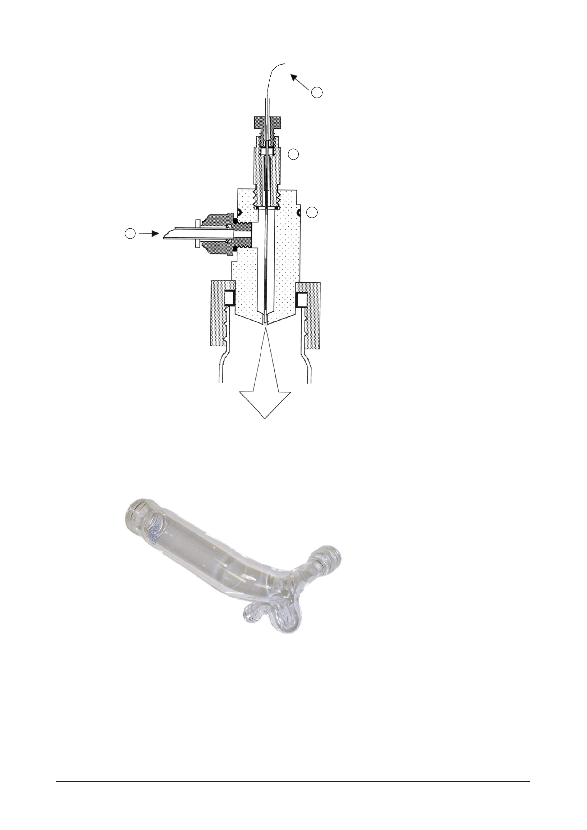
1
2
3
4
a Liquid inlet
b Coloured seal
Fig 4.3: Design of the nebulizer
Fig 4.4: Glassware chamber
c Ring
d Gas inlet
15
4 Description of function
C-650 Operation Manual, Version B
Page 16
4.2.2 Evaporation of the solvent
A heated tube is used to evaporate the solvent. The exit of the heated tube leads directly into the
detection chamber.
In liquid chromatography, water and organic solvents with low boiling points are typically employed (e.g. CH3OH, CHCl3, CH3CN). A typical mobile phase for a reverse phase separation using Evaporative Light-Scattering Detection might be CH3OH/H2O (60/40) while a typical mobile
phase for normal phase separation might be C6H14/CHCl3 (6 0/40).
If acids, bases and salts are used to modify mobile phase to provide the desired separation, they
should be able to be readily evaporated, sublimed or decomposed into gases in the evaporation
tube. Mobile phase modifiers that are commonly used when an Evaporative Light-Scattering
Detector is employed include NH4OH, (C2H5)3N, NH4 Acetate, NH4 Formate, HCOOH, CH3COOH
and CF3COOH.
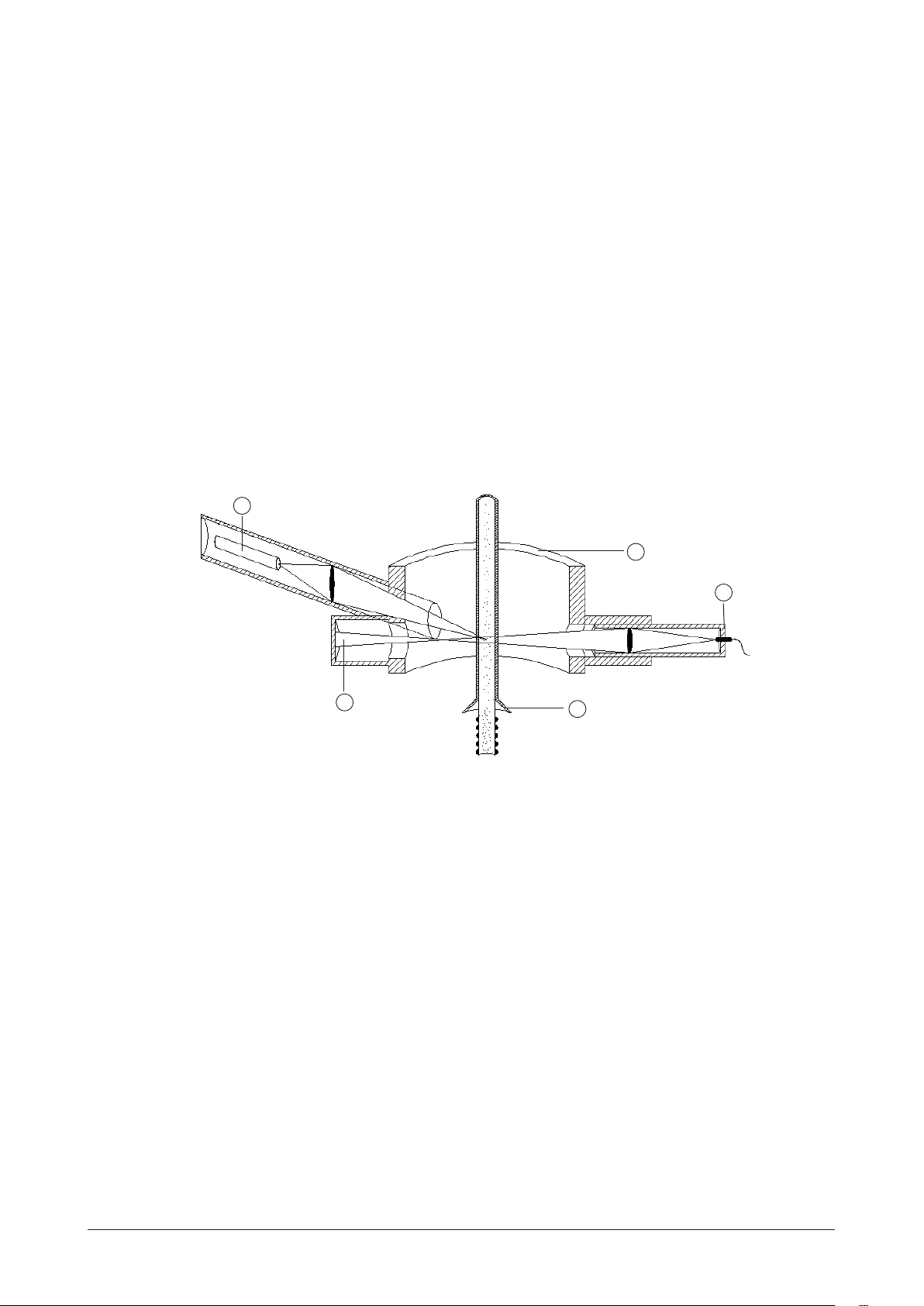
4.2.3 Detection
The carrier gas transports the microparticles from the heating tube into the detection chamber
(Fig 4.5).
1
2
3
5
a Photomultiplier
b Detection chamber
4
d Additional gas
e Light trap
c LED
Fig 4.5: Detection chamber
The detector chamber contains a Light Emitting Diode (LED) and a photomultiplier that is positioned at an angle of 100° with respect to the light beam (Fig 4.5). When the carrier gas contains
microparticles, the light is scattered and is detected by the off-axis photomultiplier.
The intensity of the scattered light is a function of the mass of the scattering particles and generally follows an exponential relationship, which is shown in the following equation.
16
I = k m
b
where: I is the intensity of light
m is the mass of the scattering particles
k and b are constants
4 Description of function
C-650 Operation Manual, Version B
Page 17

A plot of log I versus log m provides a linear response. The values of the constants (k and b) are
dependent on a variety of parameters (e.g. the temperature and the nature of the mobile phase).
An inlet to provide additional gas is located immediately before the detector chamber to provide
a concentric shield for the carrier gas. This serves to eliminate diffusion of the carrier gas and
eliminate contamination of the detection chamber.
4.3 Eluent flow splitting
The C-650 detector is designed to work with flow rates from 0.1 to 5mL/min. In preparative chromatography applications, the flow rate is mostly higher than 5mL/min. The BUCHI preparative
chromatography systems can deliver flow rates up to 250mL/min. For preparative applications,
the eluent flow rate coming out of the chromatography column must be split into 2 different flow
rates:
• One part (usually about 1mL/min) is directed to the C-650 and this part of the sample is
destructed by the evaporation and diffraction process.
• The other part is directed to the fraction collector to collect the detected compounds.
The working principle is shown below:
Flow splitter
≤ 250mL/min
Pumping system
Fig 4.6: Working principle of the flow splitting
UV
Column
Detector
(optional)
≤ 5mL/min
Fraction
Collector
ELSD
17
4 Description of function
C-650 Operation Manual, Version B
Page 18

5 Putting into operation
This chapter describes how the device is installed and gives instructions on initial startup.
NOTE
Inspect the device for damages during unpacking. If necessary, prepare a status report immediately to inform the postal company, railway company or transportation company.
Keep the original packaging for future transportation.
5.1 Installation site
Put the device on a stable, horizontal surface. Consider the maximum product dimensions and
weight. Obtain the environmental conditions as described in section 3.2 Technical data overview.
Installation prerequisites:
• Make sure, the device is not subject to drafts or significant temperature changes.
• Do not place it near air conditioning vents, windows, ovens, etc.
• Make sure that access to the power supply to disconnect the device must be kept at any
time.
• Make sure to leave a distance of at least 20cm between the device and another object or
wall.
• Place the detector close to the outlet of the column to minimize extra column band broaden-
ing which would reduce the resolution of the choromatographic separation.
•
WARNING
Death or serious injuries by use in explosive environments.
• Do not operate the device in explosive environments
• Do not operate the device with explosive gas mixtures
• Before operation, check all gas connections for correct installation
• Directly withdraw released gases and gaseous substances by sufficient ventilation
CAUTION
Risk of minor or moderate injury by heavy weight of the device.
• Consult a second person to lift the device
• Do not drop the device
• Place the device on a stable, even and vibration-free surface
• Keep limbs out of crushing zone
• To transport the device, place your hands under the device
NOTICE
Risk of device damage by liquids or mechanical shocks.
• Do not spill liquids over the device or its components
• Do not move the device when it is loaded with sample liquid
• Keep external vibrations away from the device
• Safely attach the device to the bench in earthquake prone regions
18
NOTE
As a destructive detector, the C-650 should be the last one in the flow path or can be used with
a split t e r.
5 Putting into operation
C-650 Operation Manual, Version B
Page 19

5.2 Electrical connections
NOTE
External c
onnections and extension lines must be provided with a grounded conductor lead
(3-pole couplings, cord or plug equipment). All used power cords must meet the input power
requirements.
It is recommended that all components of the Flash system are connected to a common ground.
The detector should not be connected to an electrical line which also serves units with a large
power drain or which may be subject to power surges. Such units include refrigerators, ovens,
centrifuges and fume hoods.
NOTICE
Risk of device damage by wrong mains supply.
• External mains supply must meet the voltage given on the type plate
• Check for sufficient grounding
All electrical connections are made via the supply panel (Fig 5.7) on rear panel.
Connecting the Recorder/Integrator:
If a recorder or integrator is employed, connect the recorder input to the 1V output terminal on
the rear panel of the detector (Fig 5.7) and to the appropriate socket on the recorder/integrator.
Connecting the External Autozero:
If the external autozero function is to be employed, plug the cable that is supplied into the Ext
Autozero socket on the detector (Fig 5.7) and to the appropriate socket on the controlling device
(e.g. autosampler, pump, etc.).
Refer to section 6.2.2 to operate external autozero signal.
19
Connecting the External Events Cable:
If the external events functions are to be employed, plug the cable that is supplied into the appropriate socket on the back panel of the detector (Fig 5.7) and to the appropriate socket on the
controlling device (e.g. autosampler, pump, etc.).
The white cables are contact closure “output” cables that provide the ready/non-ready information to an external device. The detector will be in the “not-ready” mode (the contact will be in
closed position) if any one of the following conditions is observed:
• The lamp is off.
• The temperature is not at the indicated setpoint.
• The temperature is at the indicated setpoint but is not stable.
• The pressure is below 2.0bar.
NOTE
The electrical consumption of the controlled device must not exceed 20mA under 12VDC.
5 Putting into operation
C-650 Operation Manual, Version B
Page 20

The blue cables are contact closure “input” cables that are used to power the unit down (see
section 6.5) via a signal from an external device to the detector..
Connecting the power cord:
Place the ON/OFF switch to the OFF position and plug the power cord into the socket on the rear
panel of the detector.
Do not turn on the power at this time.
The power cord of this detector contains three wires which must be connected to a grounded
line. All components of the chromatographic system should be connected to a common ground.
If a two wire outlet is used, make certain that an adapter is used to connect the third wire to
ground.
5.3 Gas supply
A supply of filtered, oil-free clean gas (e.g. N2 or air if aqueous mobile phase) is required to operate the detector. Pure gas is not required as gas is only a carrier vector for the solid particles (e.g.
air from an air compressor is acceptable if unreactive with analysis).
The gas supply should include a pressure gauge. The pressure should be set at 2bar. The unit
is connected to the gas supply via the 6.0mm plastic tubing (supplied) using the fitting on the
upper left corner of the supply panel on the rear of the detector.
1
2
a Gas inlet
b RS-232
c External events
Fig 5.7: Supply panel
4
3
5
6
d 1V output
e External autozero
f Main power
20
5 Putting into operation
C-650 Operation Manual, Version B
Page 21

After Parafilm is removed from the detector gas inlet, the tubing should be cut and firmly inserted
into the fitting as shown below.
1
a Cutting the tube square
b Inserting the tube into the fitting until it bottoms
Fig 5.8: Inserting the gas inlet tube
2
3
c Pull the tube to check engagement of
the grab
Two pieces of tubing are provided. If you are using the device with an external filter, connect the
gas source to the filter and then connect the filter to the back of the unit.
Make certain that no tube damage or inappropriate installation could allow a gas leak in laborator y.
To remove the gas inlet tube (if necessary); refer to Fig 5.9.
To remove the tube, disengage the grab ring teeth by a
simple manual pressure on the push sleeve and withdraw the tube from the fitting.
21
Fig 5.9: Removing the glass inlet tube
5 Putting into operation
C-650 Operation Manual, Version B
Page 22

5.4 Exhaust venting and drain requirements
WARNING
Risk of toxic fume inhalation.
• Always route the black exhaust tube from the detector into a ventilated fume hood or
exhaust vent.
The exhaust and drain should not be allowed to enter the laboratory atmosphere and any appropriate accessory (e.g. solvent filter) should be disposed of in a manner that meets the local
regulatory authorities for health and safety requirements.
The black exhaust tube from the detector can be cut and should be directed into a ventilated
fume hood or exhaust vent.
The vacuum must be moderate to avoid turbulence in the glass cell siphon or liquid spilled into
the evaporation tube.
Avoid loops or bends in the black exhaust tubing which could cause condensation traps and
could lead to poor results.
If gas from the hood enters the detector (i.e. a negative pressure exists between the detector and
the fume hood), it is possible that foreign material from the hood could contaminate the detector.
Install the drain tubing (it can be cut) in a way to the siphon outlet aligns straight to the waste container without loops or bends-, so that the waste liquid flows smoothly through the drain tubing.
Fix the drain tubing at the inlet of the waste container so that the end of the drain tubing never
dives into the liquid in the container.
NOTE
Ensure that the ParafilmTM is removed from the exhaust tube before installing the unit.
The drain tubing must be directed to an appropriate container regarding to the solvent nature.
The user is responsible for decontamination or recycling of any residue, regarding to the local
authorities environmental requirements.
Please check your local regulatory authorities for health and safety requirements.
The black exhaust line on the back of the unit should be vented to a fume hood. Make certain
that the fume hood withdraws gas from the detector (i.e. there should be a positive pressure between the detector and the hood). Verify that no tube damage or inappropriate installation could
allow a gas leak in laboratory.
Install the vent tube so that it cannot become blocked or bent, or restrict the gas flow from the
detector to the hood in any way.
Avoid long tube installations in upward direction creating condensation dropping back into the
detector.
If an extension tube is required (i.e. the supplied tube is not long enough), a suitable length of
¾”ID of PVC tubing can be fitted over the exhaust tubing.
22
5 Putting into operation
C-650 Operation Manual, Version B
Page 23

5.5 Installing the nebulizer/glass chamber assembly
ParafilmTM is used to cover various openings inside the compartment, nebulizer and glassware to
prevent dust particles from entering the detector during shipment.
NOTE
When installing the transparent black front cover, first fix its right side, and then push its left side.
When removing the front cover, pull only its left side.
The installed nebulizer/glass chamber assembly is shown in Fig 5.10.
4
5
6
3
2
1
a Siphon overflow
b Gas one-way valve
c Gas inlet fitting
d Nebulizer
Fig 5.10: Installing the nebulizer/glass chamber assembly
7
e Nut
f Glass chamber
g Nut
23
To install the the glass chamber:
Remove the ParafilmTM from all detector openings and from the nebulization cell.
Position the glass chamber as shown in F i g 5.10 and tighten the black nut at the bottom. The
glass chamber should be flush with the back wall as shown in Fig 5.11.
Fig 5.11Fixing the tip of the glass chamber
5 Putting into operation
C-650 Operation Manual, Version B
Page 24

Use the large black nut to position the nebulizer on the glass chamber.
Fill the siphon overflow on the nebulizer/glass chamber assembly with the mobile phase that will
be used for the separation. If you are using a very volatile solvent (e.g. hexane or CH2Cl2), then
use water to fill the overflow. The liquid should fill the bent part of the siphon, but should not pool
in the bottom of the evaporation tube.
Make sure that no liquid leak could affect the detector performance or create laboratory pollution.
5.5.1 Connecting the siphon overflow
Attach a Tygon drain tube assembly to the end of the siphon tube using the tapered hose connector and lead the tube to waste and drain. Locate the tube in such a way that the discarded
part of the solvent can flow freely from the siphon and ensure that the end of the tube is not immersed in the collected liquid. Make sure that liquid waste container complies with the solvent
nature.
Ensure that no siphon liquid leak could affect detector performances or create laboratory pollution.
Install the drain tubing (it can be cut) in a way to the siphon outlet aligns straight to the waste container without loops or bends, so that the waste liquid flows smoothly through the drain tubing.
Fix the drain tubing at the inlet of the waste container so that the end of the drain tubing never
dives into the liquid in the container.
A drain tube with a bend or immersing the liquid will create pressure fluctuations in the detector
and will lead to poor results.
If the solvent that you are using is not compatible with Tygon (e.g. THF), use a piece of PTFE tubing or any material you know compatible with your solvent in its place.
Please check your local regulatory authorities for recycling solvents and health and safety requirements.
5.5.2 Connecting the nebulization gas to the nebulizer
Attach the nebulization gas tube coming out from the front panel to the nebulizer gas inlet fitting
located on the nebulizer side. Refer to Fig 5.10.
NOTE
Make sure you are using the correct black gas tubing orientation, where the white one-way valve
is at the lower end (near the gas arrival).
24
5 Putting into operation
C-650 Operation Manual, Version B
Page 25

5.6 Installing the flow splitter
5.6.1 Connecting the flow splitter
The flow splitter comes as complete kit (article number 11059007) and has to be mounted inside
the detector as shown below:
1
2
3
8
7
Fig 5.12: Detection chamber/Flow splitter
a Fastening screw e Inline filter
b Flow adjustment knob f Flow from column outlet
c Union fitting to connect the splitter to
the nebulizer
g Flow to ELSD nebulizer
h Restriction capillary ID 0.10mm
d Flow to fraction collector
4
5
6
1. Fasten the splitter with the fastening screwa to the left side of the ELSD.
2. Connect the following tubings to the splitter kit:
• Outletf from the column
• Connection tubingd to the fraction collector
NOTE
Do not connect the splitter to the ELSD nebulizer before having adjusted the flow rate to
1mL/min.
Recommendation:
For preparative chromatography applications connect the column to the splitter after the conditioning step.
5.6.2 Adjusting the flow rate of the ELSD splitter
1. Remove the protecting sticker from the flow adjustment knob and keep the predefined
adjustment.
2. Start the pumping system with the appropriate eluent for your application.
3. Check the flow rate. If the flow rate is not adjusted at 1mL/min, adjust the flow rate with
the flow adjustment knob until the delivered flow rate represents about 1drop/second,
which is about 1mL/min (±10%). Measure the flow rate using a graduated cylinder
25
5 Putting into operation
C-650 Operation Manual, Version B
Page 26

flask. This adjustment requires only a small rotation of the knob. Too big rotation could
generate too high back pressure (about half clockwise rotation).
NOTE
The flow splitter is delivered equipped with a black restriction capillary having a 0.10mmID. This
configuration is especially suited for normal phase separations using solvents with low viscosity.
For reversed phase applications using solvents with viscosities higher than 0.5cP, this capillary
must be replaced with the violet restriction capillary having a 0.15mmID (ArtNo11059075).
5.6.3 Connecting to the ELS nebulizer
1. Stop the pumping system.
2. Connect the splitter to the ELSD nebulizer using the provided union fitting
(ArtNo044302) (position c in Fig 5.12).
5.7 Powering up the device
Place the ON/OFF switch to the OFF position and plug the device into the wall socket. Turn on the
unit via the ON/OFF switch. The display will present the version number and date it was created
for a few seconds (the version number should be recorded as it may be required for service or
troubleshooting) and will then present the Software option information (activated or not) and then
will present the signal (which should be 0mV or very close to it), the temperature (which should
be the ambient temperature), the pressure (which should be zero or very close to it) and the gain.
Avoid leaks at all connections and check for leakages when you switch the pump on. Install the
black front panel cover, first fix its right side, and then push its left side.
NOTE
The liquid level in the siphon must be stable and should be equal at both sides. If the vacuum is
too strong, liquid is drawn into the evaporation tube or generate air bubbles from the drain tube
and both resulting in bad measurement results.
5.8 Control panel
The Control Panel (Fig 5.13) includes a digital display and a number of buttons that are used to
enter data.
Fig 5.13: Control panel
5.8.1 Digital display
The digital display presents information about the present status of the detector and is used to
enter a variety of parameters. When the detector is switched on, the display will show a greeting
message for a few seconds which includes the version number and date.
26
5 Putting into operation
C-650 Operation Manual, Version B
Page 27

After the detector has completed the initialization procedures, the Status screen (Fig 5.14) will be
Signal Temp Press Gain
001 26°C 3.5b 1
presented. The signal should be close to zero.
Fig 5.14: Status screen
The user interface is provided via a series of screens that are described in section 5.8.2. Some
screens present information about the device status and cannot be edited by the user (e.g. the
Status screen), while other screens (e.g. the Temperature/Gain screen, Fig 5.16) are used to enter
the desired set points.
The keys on the control panel are used to provide the following functions:
Used to increase the present value of a user settable parameter (e.g. the offset)
by 1 unit. If you keep the key pressed, the rate of change of the parameter will
increase.
Used to decrease the present value of a user settable parameter (e.g. the offset)
by 1 unit. If you keep the key pressed, the rate of change of the parameter will
increase.
Validates the value of the parameter that you have edited.
ZERO Sets the present signal for the detector to zero.
LED Is used to power up the LED in the detector. When the LED is lit, the keyboard
LED immidiately above the button will be illuminated.
Changes the active line on the display to the next (previous) line or the next
(previous) screen.
Moves the cursor on the display to the next (previous) field.
5.8.2 User interface
27
The Status screen (Fig 5.14) is the default screen and is presented after initialization of the detector. In addition, it will be automatically presented again if you have accessed another screen and
have not made any keystroke within a few seconds.
Each parameter change must be validated with OK or the change will not be applied.
Status screen
The Status screen (Fig 5.14) presents the present conditions of the detector. This screen cannot
be edited, but the desired offset can be set via the Offset screen (Fig 5.15), the temperature and
5 Putting into operation
C-650 Operation Manual, Version B
Page 28

gain can be set via the Temp/Gain screen (Fig 5.16) and the pressure units can be selected via
Signal Oset (mV)
000
Temp: 50 °C
Gain: 1
the Noise Filter/Pressure Unit screen (Fig 5.18).
Temperature value blinks if desired temperature is not reached and stable. The pressure value
blinks if the gas pressure is lower than 2.0bar.
When the button is pressed; the Offset screen (Fig 5.15), which is used to select the desired
offset is displayed.
Offset screen
Fig 5.15: Offset
To increase the offset value, click on the key. If you press the button quickly, the offset will
increase by 1; if you press and hold the button, the value will increase at the rate of 20mV/sec.
Once you have set the desired offset, press the button to validate the new value.
When the device is Autozeroed, the Autozero operation updates the Offset value to set the Signal
to 0mV.
Press the button to access the Temp/Gain screen (Fig 5.16).
Temperature/Gain screen
28
Fig 5.16: Temp/Gain screen
The Temp/Gain screen is used to set the desired Temperature and Gain. When the screen is
accessed, the cursor is on the Temp setting. This setting can be changed with the and
buttons and validated by the button. The temperature range is 20 to 100°C.
5 Putting into operation
C-650 Operation Manual, Version B
Page 29

When the detector is powered up or if you change the temperature, the temperature may first
Output Signal Value
After AZ: 000 mV
overshoot the setpoint slightly and then stabilize at the desired point. This initial overshoot is due
to the regulation of the device and normal.
NOTE
To maintain appropriate temperature control, when the lowest temperature is required, it should
be set at least 5°C above ambient. Temperature stabilization typical time is 30 minutes. Please,
note that the stabilization time for temperature close to the ambient temperature may be higher.
When you press the button, the Gain field can be edited. The gain range is from 1 to 12,
each increment of one unit increases the gain by a factor of 2 (e.g. if you change the gain from
1 to 4, the gain is increased by a factor of 8) and the full range of the gain is 1 to 2048. After you
have validated the desired gain setting, press the button again to display the Autozero Offset
screen (F i g 5.17 ).
Autozero offset screen
Fig 5.17: Autozero offset screen
This screen is used to allow the signal to reach the desired value when performing an autozero
(by keyboard or external contact closure).
This function can be helpful when the user wishes to have a positive signal value instead of zero,
especially with some acquisition systems which have only positive signal acquisition capability.
This setting can be changed with the and buttons and validated by the button.
After you have set the desired autozero offset, press the button to display the Noise Filter/
Pressure Unit screen (Fig 5.18).
29
5 Putting into operation
C-650 Operation Manual, Version B
Page 30

Noise Filter/Pressure unit screen
Filter: 1 s
Press Unit: bar
LED: ON #H
Time elapsed: xx h
Fig 5.18: Noise Filter/Pressure unit screen
The Filter/Pressure Unit screen is used to indicate if digital filtering is desired for the signal data
(improves signal-to-noise ratio) and the desired units for the pressure display.
When the screen is presented, the cursor is on the Filter field. By pressing or keys, you
change the filtering strength within the following range:
“NO”: no filtering.
0.5s: 0.5 second moving average filtering.
1…10s: 1 to 10 seconds moving average filtering.
NOTE
For better results, the digital Filter should be used unless the peak(s) of interest are very poorly
resolved (e.g. when Rs<1.5).
Default value is 1sec., corresponding to a peak width of approximately 2sec. at half-height. User
manual section 6.4.5 details Filter optimization.
If you have changed the value, press to validate it before you press the button to access
the Press Unit line. The pressure unit line allows for the selection of kPa, bar or psi for pressure
units, the desired selection is made via the or key, and validated by the key. When you
press the button, the LED screen (Fig 5.19) will be displayed.
LED screen
30
Fig 5.19: LED screen
The LED screen is used to turn the light source On/Off and is equivalent to the Light Source button on the control panel. Use the button followed by the button to turn the LED on and the
5 Putting into operation
C-650 Operation Manual, Version B
Page 31

button followed by the button to turn it off.
Gas Valve: Open
Prog Time: 0 min O
Powerdown Mode: General
Activate?
The # hours field indicates the number of hours that the LED has been in use. The lifetime of the
LED is approximately 5000h. When this period has been reached, a message indicating that the
maximum usage of the lamp has been exceeded will be presented when the unit is powered up
and the orange LED on the keyboard blinks.
NOTE
When you press the button, the Gas Valve screen (Fig 5.20) will be displayed.
Gas valve screen
Fig 5.20: Gas valve screen
The Gas Valve screen is used to open/close the gas valve and to setup a program to close the
gas valve after a user selected time period. To use this feature, move the cursor to the time field,
indicate the appropriate time, then move the cursor to Off and use the or key to select
On and press .
When you press the button, the power down screen (Fig 5.21) will be displayed.
Power Down screen
The Power Down screen (Fig 5.21) is used to indicate which features should be shut down upon
receipt of a power down signal from an external source or from the menu.
31
Fig 5.21: Power Down screen
5 Putting into operation
C-650 Operation Manual, Version B
Page 32

The three options provided for external shutdown are summarized in the following table:
Total Lifetime Elapsed
Activate? ########hrs
Mode Photomultiplier Lamp Heating Gas flow
General Off Off Off Off
Standby Off Off On Off
Cleaning Off Off On On
To select the desired Power Down mode, use the or key to access the desired mode and
then press to validate the selection.
NOTE
It will take a few minutes to attain operating status from General power down mode, as the temperature must stabilize.
Once the Power Down mode has been chosen and validated, the detector can be powered
down in two ways:
External event cable power down contact closure: The detector will stay in the selected
power down mode while the contact remains closed. It comes back in normal mode when the
contact closure is released.
Power down screen: Press the button to access the power down screen, then press
again the button to place the cursor on the Power down activate line. Validate with to put
the detector in power down mode.
NOTE
To leave the power down mode, release the contact closure if power down has been activated
by external event or press any key if power down has been activated from the Power down
screen.
When the cursor is on the Power down activate line, pressing the button will present the
Total Lifetime Elapsed screen (Fig 5.22).
Total Lifetime Elapsed screen
32
Fig 5.22: Total Lifetime Elapsed screen
The Total Lifetime Elapsed information screen indicates the usage of the detector and cannot be
edited by the user. When you press the button, the Serial Number screen (Fig 5.23) will be
displayed.
5 Putting into operation
C-650 Operation Manual, Version B
Page 33

Serial Number Screen
Serial Number
#########
Firmware Version: V.v
Firmware Date: MM/YY
Fig 5.23: Serial Number screen
The Serial Number screen cannot be edited by the user. The last character indicates the detector hardware revision. When you press the button, the Firmware screen (Fig 5.24) will be
displayed.
Firmware Screen
33
Fig 5.24: Firmware screen
This information screen presents the firmware Version Bnd date, where MM is the month, and YY
the year. The Firmware screen cannot be edited by the user.
When you press the button, the Factory Menu Code screen (Fig 5.25) will be presented.
5 Putting into operation
C-650 Operation Manual, Version B
Page 34

Factory Menu Code Screen
Factory Menu Code ____
Authorized persons only
Fig 5.25: Factory Menu Code screen
The Factory Menu Code screen is used by the service engineer to access a variety of service
features and is not designed to be employed by the user.
5.9 Initial test procedures
5.9.1 Preliminary activities
This section presents a protocol that can be used to ensure that the detector is working in the
proper way.
When the device is set-up, the procedures indicated below should be performed to determine
the specific characteristics of your unit. We suggest that you save the results in a permanent
location, as they can be very useful when you are performing troubleshooting activities.
Before starting the tests for a new device or after storage, flush the detector with water at a flow
of 1mL/min for at least 15minutes.
The following activities should be performed:
Power up the device. When the detector is shipped from factory, the gain is set to 1 and the
offset to 0mV. The Signal screen should indicate 000 (or a very small signal).
Access the Temperature/Gain screen, set the temperature to 50 °C and press . View the
Status screen and verify that the temperature is rising to the setpoint on the Status screen. Temperature regulation is stable when the Temperature value stops blinking.
34
5 Putting into operation
C-650 Operation Manual, Version B
Page 35

When the detector is powered up or if you change the temperature, the temperature may first
overshoot the setpoint slightly and then stabilize at the desired point. This initial overshoot is due
to the regulation of the device and should not be a concern.
Provide gas to the detector and adjust the pressure to 2bar (29psi). If the pressure is less than
1,5bar (21psi), the pressure value blinks, indicating that the detector is not ready.
Make certain that the pressure of gas supplied to the detector is less that 4.5bar (67psi). If the
pressure increases above 4.5bar (67psi), the pressure sensor may be damaged. This damage
is not covered by the warranty.
If you have an external gas gauge, make sure that the external reading and the reading on the
Status screen are the same.
Press the „ZERO“ button. The signal should be close to zero and remain constant.
Set the noise filtering to 1second (refer to Fig 5.18).
5.9.2 Electronic noise test
To determine the electronic noise:
Do not switch the light source on. Do not switch the pump on (no solvent flow).
Make sure that the siphon is filled and the nebulizer inlet connector is blocked with ParafilmTM to
avoid a Venturi effect.
Set gas pressure to 2bar (29psi) and temperature to 50°C. Wait for stable temperature.
Set gain 12 and monitor the signal for a period of 5 min. The variation in the signal should be less
than +/-2mV (there may be some spiking of the signal).
Record the level and autozero the detector again.
5.9.3 Background noise (stray light) test
To determine the background noise:
Do not turn on the pump (no solvent flow).
Make sure that the siphon is filled and the nebulizer inlet connector is blocked with ParafilmTM to
avoid a Venturi effect.
Set gas pressure to 2bar (29psi) and temperature to 50°C.
Switch on the light source.
Change the Gain to 1.
Set the offset to 0mV.
Set the offset after Autozero to 0mV (refer to Fig 5.17).
Autozero the detector.
35
Change the Gain to 12.
Wait 15 minutes for stabilization and record the signal level. The expected level is typically 100mV
to 150mV. The exact value will vary slightly and small deviations should not be a cause for concern.
5 Putting into operation
C-650 Operation Manual, Version B
Page 36

5.9.4 Solvent noise test
To determine the solvent noise:
Ensure that the gas is flowing at 2bar (29psi), the temperature is set to 50°C and stable and
the pump is switched off.
Switch on the light source and set the gain to 12 and monitor the signal. Do not autozero the
detector. The signal may be negative.
Bypass the column and connect the detector to the mobile phase delivery system and pump the
solvent that you expect to use for your analyses through it at a flow rate of 1mL/min.
Monitor the baseline for a few minutes.
If water is used as the solvent, the signal should be less than 10mV. Higher values could be observed if non-HPLC grade water (with a higher non-volatile residue) is used.
If an organic solvent is used, the signal should be less than 200mV.
For mixed aqueous/organic solvents, the expected signal is approximately linear with respect to
the concentration of organic phase in the solvent (e.g. a water/organic solvent (50:50) mixture
should provide a signal of approximately less than 100mV).
NOTE
The purity of the solvent is critical for a low background noise. The sensitivity is inversely proportional to the solvent noise.
In most cases, distilled water and HPLC grade solvents are satisfactory. When you are comparing solvents from different sources, the most critical parameter is the Residue After Evaporation;
this parameter should be less than 1ppm to maximize the sensitivity of the detector.
If the device fails the Solvent Noise test, it is most likely due to an impurity in the solvent rather
than a fault with the device. If changing the solvent source does not solve the problem, it may be
necessary to decontaminate the device as described in section 8.7.2 or clean the nebulizer as
described in section 8.5.
When filtering the solvent, verify that it does not extract any contaminant from the filter.
The mobile phase should not contain non-volatile solvent modifiers. Volatile solvent modifiers
(e.g. CHOOH, CH3COOH, CF3COOH, NH4 Formate, NH4, Acetate, (C2H5)3N)…) can be used, but
they may increase the noise level at high gain settings. In addition, the solvent should not contain
preservatives, (e.g. Tetrahydrofuran may contain BHT as a stabilizer).
36
5 Putting into operation
C-650 Operation Manual, Version B
Page 37

5.9.5 Column noise test
NOTE
When strongly retained compounds are slowly eluted from the column, excessive noise will be
observed.
To determine the column noise:
Turn off the pump and connect the column.
Restart the pump and allow the mobile phase to flow through the system. It is suggested that
you flush the column with a strong solvent for a few minutes before attaching it to the detector.
Set the gain to 12 and monitor the baseline for a few minutes. A suitable column will provide a
baseline that is 20–50mV above the solvent baseline.
NOTE
If the mobile phase contains acidic modifiers (e.g. CF3COOH), disconnect the detector and wash
the Chromatography system for 12h before starting to analyze unknown samples. This wash
should be performed after the column noise test is completed, but need not to be performed
after each analysis.
37
5 Putting into operation
C-650 Operation Manual, Version B
Page 38

6 Operation
This chapter describes the operations that should be performed on a routine basis when you
want to collect chromatographic data using the C-650 and gives examples of typical device applications and instructions on how to operate the device properly and safely.
6.1 Preparing the device for operation
CAUTION
Risk of fire due to flammable liquids!
• Check all tubes for correct connection before starting the device.
• Make sure all tubes are in good condition (no cracks or cuts).
To prepare the detector for operation:
• Power up the detector by pressing the switch on the rear panel.
• Open the gas distribution valve and set the pressure to 2bar (29psi). The pressure is indi-
cated on the Status screen.
• Ensure that the overflow siphon for the nebulization chamber contains sufficient liquid. If
necessary, pump few mL of solvent through the device to fill the siphon.
• Select the desired temperature. The temperature is set on the Temp/Gain screen, which is
accessed by pressing the button two times when the Status screen is displayed.
• Start the mobile phase flow through the device and allow the overall system to operate for
at least 15 minutes to ensure that all components are equilibrated and a stable baseline is
obtained.
• Switch on the LED light source of the detector by pressing the LED button on the control
panel.
NOTE
The Solvent Noise test (section 5.9.4) and the Column Noise test (section 5.9.5) should be performed to verify that the detector is functioning in a proper manner.
NOTE
The liquid level in the siphon must be stable and should be equal at both sides.
6.2 Auto-zeroing the detector
6.2.1 Manual
To auto-zero the detector:
• Set the Gain to the desired value. The gain is set on the Temp/Gain screen, which is ac-
cessed by pressing the button two times when the Signal screen is displayed.
• Press the “ZERO” button. The detector will be automatically auto-zeroed at this point.
• If the signal is to be offset, set the offset at this time. The Offset screen is accessed by
pressing the button when the Status screen is displayed.
NOTE
The offset must be selected after the detector is auto-zeroed, as the Auto-zero operation sets
the signal to 0.
NOTE
If you change the gain selection, make sure that the detector is auto-zeroed again before taking
any measurement.
38
6 Operation
C-650 Operation Manual, Version B
Page 39

6.2.2 External
To auto-zero the detector, a contact closure signal or a TTL signal is used to short circuit the
contacts. The signal should be at least 1second long, with a maximum current of 20mA at 5V.
If a TTL signal is used please make sure to use the correct polarity identified on the cable.
6.3 Routine operation of the detector
In general, operation of a Chromatography system with Evaporative Light-Scattering Detection is
similar to operation of the system with other detectors.
During operation of the detector, the following should be considered:
CAUTION
Risk of minor or moderate injury by hot acid fumes.
• Do not operate the system with faulty parts
• Check device setup for proper sealing before use
• Do not inhale process fumes
• Operate the device inside an active fume hood
• Do not move the device or parts of it during operation
NOTICE
Risk of device damage by leaking liquids.
• Do not operate the system with faulty parts
• Check device setup for proper sealing before use
• Make sure that there is a continuous flow of gas through the detector (i.e. no constriction). If
a vacuum is used, ensure that the vacuum effect will not disturb the detector (section 5.4).
• Ensure that the siphon is filled with liquid at all times. The overflow from the siphon should be
collected in a suitable container.
• Make sure that all flow connections are properly tight. In case of any leak, switch off the
pump immediately and remove the liquid.
• Never exceed a gas pressure of greater than 4.5bar (67psi).
• Avoid the use of solvent or compounds that could corrode the detector. The mobile phase is
in contact with glass and PTFE tubing and the evaporation tube is made of stainless steel.
6.4 Optimizing the performance
6.4.1 Selecting the optimum temperature
There are two factors that should be taken into account when selecting the optimum temperature for the detector:
39
• Increasing temperature will optimize the evaporation of the mobile phase.
• Decreasing temperature will minimize the decomposition of thermally labile compounds and
the volatilization of semi-volatile compounds.
A very reasonable start is to set the temperature to 60°C if an aqueous mobile phase is used
and 40°C if an organic mobile phase is used (these temperatures are suggested for a flow rate
of 1mL/min). At higher flow rates, more elevated temperatures may be required to minimize the
noise.
6 Operation
C-650 Operation Manual, Version B
Page 40

NOTE
If the mobile phase used is not easily volatile, such as DMSO or DMF, temperature should be
increased to allow correct evaporation process.
The temperature can be adjusted during the method optimization process.
If you suspect that the compound of interest is thermally labile or semi-volatile, a lower temperature could be used to improve the sensitivity by reducing the thermal decomposition or
evaporation. For a given flow rate and solvent, there is, however, a point at which the noise in the
chromatogram is dramatically increased because not all of the mobile phase is vaporized.
As an example, consider the analysis of caffeine with evaporation temperatures of 30°C and
60°C (Fig 6.26) [the conditions for the separation are – Column: ODS KromasilTM (5µm, 30×
2.1mm), Sample: 4µL (10mg/L) Caffeine]. Eluent: Water, 0.2mL/min, temperature as indicated).
It is clear that the use of a low temperature provides significantly better sensitivity for volatile and
thermally sensitive compounds.
Fig 6.26: Chromatogram of caffeine at various temperatures
The minimum temperature that can be used is dependent on the flow rate, ambient temperature
and the nature of the mobile phase.
6.4.2 Optimizing the mobile phase
Particulate matter in the mobile phase will increase the background noise.
The purity of the solvent is a critical issue in the noise. When filtering the solvent, verify that it
does not extract any contaminant from the filter.
The purity of the solvent is critical for a low background noise. The sensitivity is inversely proportional to the solvent noise.
In most cases, distilled water and HPLC grade solvents are satisfactory. When you are comparing solvents, the most critical parameter is the Residue After Evaporation; this parameter should
be less than 1ppm to maximize the sensitivity of the detector.
As an example, consider the analysis of a sample in a pure water mobile phase and a polluted
water mobile phase. It is clear that the use of an insufficient quality solvent can dramatically decrease your S/N ratio (sensitivity).
40
6 Operation
C-650 Operation Manual, Version B
Page 41

Fig 6.27:Chromatogram with variing solvent quality
The mobile phase should not contain non-volatile solvent modifiers. Volatile solvent modifiers
(e.g. CHOOH, CH3COOH, CF3COOH, NH4 Formate, NH4. Acetate, (C2H5)3N)…) can be used, but
they may increase the noise level at high gain settings. In addition, the solvent should not contain
preservatives, (e.g. Tetrahydrofuran may contain BHT as a stabilizer).
The wetted parts of the detector are made from PTFE, stainless steel, and glass. Make sure that
the solvents do not react with these materials.
NOTE
Depending on the mobile phase nature and flow rate, the suggested gas pressure 3.5bar
(51psi) may have to be adjusted in order to optimize the background noise and so Signal-toNoise ratio.
6.4.3 Sample pretreatment
If the sample contains any particulate matter, it should be filtered through a 0.2µm or 0.45µm
filter before injection.
6.4.4 Column treatment
The chromatographic column typically contains microparticles which are used to separate the
compounds of interest. Under certain conditions, the column packing will undergo chemical
and/or mechanical breakdown, this may lead to the introduction of particulate matter in the detector, which may lead to an increase in the noise.
41
NOTE
When strongly retained compounds are slowly eluted from the column, excessive noise will be
observed.
The breakdown of the column packing is dependent on a variety of factors including the particle
size, type of column packing, the manufacturer of the column and the nature of the mobile phase
(high pH may degrade silica based columns).
When you install a new column, we suggest that you pump the mobile phase through it for few
minutes before connecting it to the detector. This will flush out the microparticles that remained
in the column after its manufacture. After installing a new column, we also suggest that you perform the Column Noise test (section 5.9.5) to obtain the baseline signal value corresponding to
this column.
6 Operation
C-650 Operation Manual, Version B
Page 42

6.4.5 Optimizing the noise filter
The Digital Filter (Fig 5.18) allows maximizing Signal-to-Noise ratio by filtering the noise. The filter
strength should be optimized according to the peak shape, and more specifically to the peak
width.
The following table proposes some Filter settings depending on peak width:
Peak width at 50% (second) Proposed filter (second)
<1 0
2 1
4 2
6 4
8 6
>10 8 and higher
These suggested values can be optimized depending on your specific chromatography, by decreasing Filter if peaks are poorly resolved (e.g. when Rs<1.5), or increasing Filter when optimizing Signal-to-Noise ratio.
Example: Comparison of digital filters using the SOP test (injection of 5ppm caffeine at gain 12).
Peak width at half-height is 2.5seconds.
Filter 0s Filter 1s Filter 2s
Signal height 124mV 122mV 110mV
Noise (ASTM) 3.2mV 1.1mV 0.7mV
Peak width (at 50%
2.5 s 2.5 s 2.8 s
height)
S/N 37 110 157
Signal-to-Noise ratio is multiplied by 3 when selecting Filter 1second without any peak broadening effect. If Signal-to-Noise ratio is more important than resolution, a Filter 2seconds or higher
can be set to improve sensitivity even better.
6.5 Powering down and shutting down the detector
If desired, some or all functions of the device can be powered down at the end of an automated
series of analyses. These power down features are described in detail in Fig 5.21.
To shut down the device:
• Turn off the pump.
• Allow the nebulization gas to flow through the detector for few minutes (30min is recom-
mended) to drain the evaporation tube and detection chamber.
• Turn off the power to the detector (if desired).
42
If you are using a mobile phase which contains salts, acids or bases, pump few mL of water or
methanol through the system before switching off the detector to prevent any deposition of substances and possible corrosion of the device.
If ELSD is used as a second detector and is not being used for some time, it is recommended to
remove it from the liquid chromatography flow path in order to avoid any clogging of the nebulizer
or deposition of substances inside the detector.
Closing gas valve while the pump is still running may result in serious nebulizer damage.
6 Operation
C-650 Operation Manual, Version B
Page 43

7 Maintenance
This chapter gives instructions on all maintenance work to be performed in order to keep the
device in good working condition.
WARNING
Death or serious burns by electric current at cleaning.
• Switch off the device
• Disconnect the power cord and prevent unintentional restart
• Wait until the device is completely dry before reconneting to mains
NOTICE
Risk of housing and device damage by liquids and detergents.
• Do not spill liquids over the device or parts of it
• Wipe off any liquids instantly
• Use ethanol or soapy water as detergent only
The ELSD C-650 Low Temperature Evaporative Light-Scattering detector is designed to require
a minimum of maintenance activities. If preventive maintenance activities are followed, the detector should provide high sensitivity measurements without intervention by the operator.
The following general recommendations are proposed:
• Maintain the detector in a clean laboratory environment.
• If the device is not going to be used for a period of time, flush out any mobile phase that
contains acids, bases or salts to prevent the deposition of foreign matter on components or
corrosion of the device.
• Only use clean gas (particle-free and oil residue-free).
Closing gas valve while the pump is still running may result in serious nebulizer damage.
If ELSD is used as a second detector and is not being used for some time, it is recommended to
remove it from the liquid chromatography flow path in order to avoid any clogging of the nebulizer
or deposition of substances inside the detector.
43
For an efficient preventive maintenance:
After each session and before shutting down the chromatography system, the ELSD should be
cleaned in order to ensure good performances.
Preventive maintenance consists in cleaning the detector before shutting down after the last
analyses:
• Let the mobile phase or solvent (recommendation: ethanol) flow to flush particles which
could remain in the detector.
• Eventually increase temperature in order to dissolve possible deposit.
• Stop the mobile phase flowing but let the gas flow at least 30min to dry to avoid particles
deposit.
• Stop the gas flow.
• Shut down the detector.
7 Maintenance
C-650 Operation Manual, Version B
Page 44

The time required for each step depends on the application, solvents, type and concentration of
the samples and should be determined accordingly.
NOTE
It is not necessary to access inside the device in routine operation. If the suggestions provided in
this chapter do not remedy the problem, contact your local distributor.
The LED used as the Light Source has a long but finite lifetime (~5000hours) and should be
replaced periodically by a skilled technician. When this period has been reached, a message
indicating that the maximum usage of the lamp has been exceeded will be presented when the
unit is powered up and the orange LED on keyboard will blink.
7.1 Customer service
Only authorised service personnel are allowed to perform repair work on the device. These persons have a comprehensive technical training and knowledge of possible dangers which might
arise from the device.
Addresses of official BUCHI customer service offices are given on the BUCHI website under.
www.buchi.com. If malfunctions occur on your device or you have technical questions or application problems, contact one of these offices.
The customer service offers the following:
• Spare part delivery
• Repairs
• Technical advice
44
7 Maintenance
C-650 Operation Manual, Version B
Page 45

8 Troubleshooting
8.1 General troubleshooting information
The ELSD C-650 Evaporative Light-Scattering Detector is designed to be incorporated into a
Liquid Chromatography system. It is important to note that the detector response reflects the
overall performance of the system, and a “problem” that is seen on the detector output may not
necessarily be a “detector problem”. In almost all cases, there is one and only one cause for a
problem. As an example of this point, if the user observes a noisy baseline, it is possible that the
problem is due to:
• The pump (e.g. a defective check valve).
• The mobile phase (e.g. improper degassing or high residue after evaporation).
• The column (e.g. elution of strongly retained components).
• The nebulizer (e.g. lack of maintenance)
• The detector (e.g. an electronic problem).
It is very unlikely that two problems occur at the same time. The role of the troubleshooting activities is to determine the cause of the problem. In the following, we assume that the operator has
already determined that other components of the system are operating in an appropriate way.
Do not disassemble the nebulizer. Disassembling the nebulizer will destroy it and this will void
the warranty.
NOTE
The control panel and device electronics do not contain any replaceable components. If the
suggestions provided in this chapter do not remedy the problem, contact your local distributor.
If the digital display does not illuminate when the detector is powered up, turn the unit off and inspect the main fuses. If necessary, replace the fuses with some of the same rating as the original
ones for all 115V and 230V units. The fuses are located inside the main power module on the
rear panel (Fig 5.7). A set of replacement fuses is delivered in the starting kit.
If the fuses are not blown or if the replacement fuses blow up again, contact your local distributor.
8.2 Initial troubleshooting activities
• Make sure that the device and all components of the detector are grounded to a true
ground.
• Check to ensure that the liquid level in the siphon is appropriate, and there is no liquid pool-
ing close to the evaporation tube inlet.
• Check that the gas pressure is sufficient and stable. The selected pressure for most applica-
tions is 2bar (29psi). Pressure above 4.5bar (67psi) can damage the pressure sensor. The
gas filter should be clean and in place. Only use gas free of oil residue.
45
8 Troubleshooting
C-650 Operation Manual, Version B
Page 46

8.3 Perform the noise test
Repeat the tests described in section 5.9 and compare the observed data to the results that
were obtained when the unit was initially installed. These tests can be very valuable to isolate the
problem.
As an example of this point, if the Electronic Noise test (section 5.9.2), Background Noise test
(section 5.9.3) and Solvent Noise test (section 5.9.4) provide results that are similar to that obtained when the unit was initially installed, but the Column Noise test (section 5.9.5) provides a
significantly different value than what was obtained at installation, it is likely that the problem is in
the column (e.g. highly retained compounds are being eluted).
8.4 Specific detector troubleshooting
• The mist from the nebulizer should be homogeneous. If it is not homogeneous, the nebulizer,
the needle or the PTFE tube may be partially obstructed. To remove the obstruction, pump a
solvent that can dissolve the foreign material. As an alternative, the nebulizer can be placed
in an ultrasonic bath to dissolve the foreign material. Instructions about cleaning of the nebulizer are presented in section 8.5.
Do not disassemble the nebulizer. Disassembling the nebulizer will destroy it and this will void
the warranty.
• If the sensitivity of the detector is low, ensure that there are no leaks in the system. Make
sure you are using a fresh sample and consider running the test using a back pressure loop
instead of a column. Alternatively, the LED may need to be replaced or the nebulizer could
be obstructed.
• If the noise test did not show that the problem could be caused by the application or the
system, a decrease in the sensitivity is often caused by the nebulizer (main cause). Clean the
nebulizer as described in section 8.5. If the sensitivity does not return to normal, the nebulizer might need to be replaced. Please note that the root cause might also be in different
module, i.e volumes injected might be too low or dead volumes in capillary connections may
cause peak broadening.
• If the detector signal is saturated or if there is a decrease in the dynamic range of the
system, it is possible that a residue is passing through the detector cell: this will lead to an
intense signal due to a significant amount of light-scattering. This residue may be a result of
the elution of strongly retained materials from the column, or may come from the solvent. To
determine the cause of the problem, bypass the column and observe the signal intensity:
• If the signal returns to normal, strongly retained materials are eluting from the column.
Flush the column with a strong solvent to elute all material.
• If the signal does not return to normal, the solvent contains a too high residue material,
after evaporation and is not suitable for use with the detector.
• If the noise of the detector without solvent is high or if ghost peaks occur, it is possible that
foreign material is present in the drift tube. In this situation, increase the temperature to
100°C and pump solvent at the rate of 2mL/min, using a gas pressure of 2bar (29psi).
46
8 Troubleshooting
C-650 Operation Manual, Version B
Page 47

8.5 Nebulizer cleaning and replacement procedures
If the mist of the nebulizer is not homogeneous, the nebulizer, the needle or the PTFE tube may
be obstructed. To remove the obstruction, pump a solvent (recommendation: ethanol) that can
dissolve the foreign material. As an alternative, the nebulizer can be placed in an ultrasonic bath
to dissolve the foreign material.
Handle the nebulizer carefully and do not disassemble the rear part of the nebulizer, which is
protected by the colored thermal seal. Improper handling of the nebulizer will destroy it and this
will void the warranty.
The nebulizer rear part is a strategic setting which mustn’t be dismounted for any reason. In case
the user has removed it, the only solution is to perform a nebulizer replacement.
If the nebulizer cannot be repaired by cleaning by pumping solvent through it or with an ultrasonic
bath, it requires a replacement.
In case the nebulizer does not produce a spray and the liquid is drawn directly to the siphon even
if the pressure display is 2bar, make sure you are using the correct black gas tube orientation
fitting for the nebulizer, where the white one-way valve is at the lower end (near the gas arrival) on
the front panel. The installed Nebulizer/Glass Chamber assembly is shown in Fig 5.10.
To remove the nebulizer from the device:
• Switch off the pump and the ELSD detector.
• Remove the black front panel cover. Pull its left side.
• Disconnect the nebulizer liquid inlet from the column
• Disconnect the gas inlet from the nebulizer by pushing
on the white inlet (refer to Fig 5.10 for details).
• Remove the nebulizer from the glass cell by unscrewing
the black plastic nut with the right hand whilst maintaining the nebulizer with the left hand. Take care not to pull
or twist the nebulizer capillary. The black nut which maintains the nebulizer on the glass cell and its seal should
be removed from the nebulizer.
47
8 Troubleshooting
C-650 Operation Manual, Version B
Page 48

• Remove the gas inlet quick fitting and the black plastic nut to avoid damaging the seals with
the cleaning solvent.
Fig 8.28: Removing parts from the nebulizer
To clean the nebulizer:
• Fill an ultrasonic bath with water. Fill a beaker (50 or 100mL) with approximately 2cm of an
appropriate solvent. The solvent is dependent on the nature of the material that is present in
the nebulizer. In most cases, ethanol is a satisfactory solvent.
• Place the nebulizer vertically in the beaker 2cm solvent bath. The nebulizer outlet should be
placed at the bottom of the bath and the nebulizer inlet liquid tubing should be pointing up.
Take care to ensure that the rear part of the nebulizer is not in contact with the solvent.
2 cm
Fig 8.29: Cleaning the nebulizer
• Clean the nebulizer for approximately 30 minutes with the solvent, and then replace the
solvent with water and clean for an additional 30 minutes.
To re-install the nebulizer or replace it by a new one or another nebulizer model
• For re-installing the nebulizer after a nebulizer cleaning, re-install the gas inlet quick fitting
and the black plastic nut with its seal.
• Reverse the order of previous steps (nebulizer removing). In case the black gas tubing has
been removed, make sure you are using the correct orientation, where the white one-way
valve is at the lower end (near the gas arrival).
• Make sure there is no liquid or gas leak at all connections and check for possible leakage
that could affect the detector performance or create laboratory pollution when you turn on
the pump.
• Install the black front panel cover, first fix its right side, and then push its left side.
• Test the nebulizer to ensure that it is working properly.
48
8 Troubleshooting
C-650 Operation Manual, Version B
Page 49

NOTE
If the nebulizer cleaning procedure does not solve the problem, contact your local distributor for
a nebulizer replacement.
In case the black gas tubing has been removed, make sure you are using the correct orientation,
where the white one-way valve is at the lower end (near the gas arrival). Avoid leaks at all connections and check for possible leakage when you turn the pump on again.
4
5
6
3
2
1
a Siphon overflow
b Gas one-way valve
c Gas inlet fitting
d Nebulizer
Fig 8.30: Installing the nebulizer/glass chamber assembly
7
e Nut
f Glass chamber
g Nut
8.6 Gas flow problems
In case of gas flow problems, please contact the BUCHI Customer Service.
8.7 Cleaning and decontamination
8.7.1 Device cleaning
CAUTION
Risk of minor burns by hot detector.
• Let the detector cool down safely for 15 minutes before cleaning.
• Switch the device off.
• Disconnect all connection cable (power cable, signal cable, autozero cable, RS-232 cable if
any, device gas input and nebulizer tubing).
• Clean the outside of the detector with a non-abrasive cloth. If necessary, a liquid such as
soapy water or ethanol can be used to remove stains or foreign material.
49
8 Troubleshooting
C-650 Operation Manual, Version B
Page 50

8.7.2 Device decontamination
• Set the evaporation temperature to 100°C and the gas pressure to 2bar (29psi).
Pump the appropriate solvent through the system at the rate of 1mL/min. The solvent will be determined by the nature of the samples that were previously analyzed by the detector. If you do not
know the nature of the sample, ethanol is a good choice. Do not use solvents that can potentially
corrode the device. Maintain the flow and temperature during 3hours at least.
• Clean the outside of the detector with a non-abrasive cloth. If necessary, a liquid such as
soapy water or ethanol can be used to remove stains or foreign material.
8.8 Light source exchange
In case the light source needs to be exchanged, please contact the BUCHI Customer Service.
50
8 Troubleshooting
C-650 Operation Manual, Version B
Page 51

9 Shutdown, storage, transport and disposal
This chapter instructs how to shut down the device, how to pack it for storage or transport, and
specifies the storage and shipping conditions.
9.1 Preparing the device for storage and transport
To prepare the device for storage and transport, unplug the power cord and remove all glass
parts from the device.
9.2 Storage and transport
Store the device at a dry place. Store and transport the device in its original packaging.
WARNING
Death or serious poisoning by contact or incorporation of harmful substances.
• Wear safety goggles
• Wear safety gloves
• Wear a laboratory coat
• Flush the device and clean all accessories thoroughly to remove possibly dangerous sub-
stances
• Do not clean dusty parts with compressed air
• Store the device and its accessories at a dry place in its original packaging
CAUTION
Risk of minor or moderate injury by heavy weight of the device.
• Consult a second person to lift the device
• Do not drop the device or its transport box
• Place the device on a stable, even and vibration-free surface
• Keep limbs out of crushing zone
51
9 Shutdown, storage, transport and disposal
C-650 Operation Manual, Version B
Page 52

10 Spare parts
This chapter lists spare parts, accessories, and options including their ordering information.
Order the spare parts from BUCHI. Always state the product designation and the part number
when ordering spare parts.
Use only genuine BUCHI consumables and genuine spare parts for maintenance and repair to
assure good system performance and reliability. Any modifications to the spare parts used are
only allowed with the prior written permission of the manufacturer.
Product Order number
C-650 Flash nebulizer 110 5 9 16 2
C-650 Glass nebulization chamber 11059164
Black plastic nut for nebulization chamber diam. 13 mm 110 5 9 241
Black plastic nut for nebulization chamber diam. 30 mm 110 5 9 24 2
Black pneumatic tube with steel fitting and one way gas valve for
110 5 9 22 7
nebulizer
Complete drain tube assembly 110 5 9 23 9
52
10 Spare parts
C-650 Operation Manual, Version B
Page 53

11 Declarations and requirements
11.1 FCC requirements (for USA and Canada)
English:
This equipment has been tested and found to comply with the limits for a Class A digital device,
pursuant to both Part 15 of the FCC Rules and the radio interference regulations of the Canadian
Department of Communications. These limits are designed to provide reasonable protection
against harmful interference when the equipment is operated in a commercial environment.
This equipment generates, uses and can radiate radio frequency energy and, if not installed and
used in accordance with the instruction manual, may cause harmful interference to radio communications. Operation of this equipment in a residential area is likely to cause harmful interference in which case the user will be required to correct the interference at his own expense.
Français:
Cet appareil a été testé et s’est avéré conforme aux limites prévues pour les appareils numériques de classe A et à la partie 15 des réglementations FCC ainsi qu’à la réglementation des
interférences radio du Canadian Department of Communications. Ces limites sont destinées
à fournir une protection adéquate contre les interférences néfastes lorsque l’appareil est utilisé
dans un environnement commercial.
Cet appareil génère, utilise et peut irradier une énergie à fréquence radioélectrique, il est en outre
susceptible d’engendrer des interférences avec les communications radio, s’il n’est pas installé
et utilisé conformément aux instructions du mode d’emploi. L’utilisation de cet appareil dans les
zones résidentielles peut causer des interférences néfastes, auquel cas l’exploitant sera amené
à prendre les dispositions utiles pour palier aux interférences à ses propres frais.
53
11 Declarations and requirements
C-650 Operation Manual, Version B
Page 54

11.2 Declaration of conformity
54
11 Declarations and requirements
C-650 Operation Manual, Version B
Page 55

Page 56

ELSD C-650
Operation Manual
Quality in your hands
BÜCHI L abortec hnik AG
CH – 9230 Fla wil 1
T +41 71 394 63 63
F +41 71 394 65 65
buchi@buchi.com
www.buchi.com
BÜCHI Labor technik G mbH
DE – 45127 Essen
Freeca ll 080 0 414 0 414
T +49 201 747 490
F +49 201 237 082
deutschland@buchi.com
www.buechigmbh.de
BUCHI I talia s.r.l.
IT – 2009 0 Assag o (MI)
T +39 02 824 50 11
F +39 02 57 51 28 55
italia@buchi.com
www.buchi.it
We are represented by more than 100 distribution partners worldwide.
Find your local representative at: www.buchi.com
BUCHI UK Ltd.
GB – Oldh am OL9 9Q L
T +44 161 633 1000
F +44 161 633 1007
uk@buchi.com
www.buchi.co.uk
BÜCHI Labortechnik GmbH
NL – 3340 AC
Hendrik-Ido-Ambacht
T +31 78 684 94 29
F +31 78 684 94 30
netherlands@buchi.com
www.buch i.nl
BUCHI (Thailand) Ltd.
TH – Bangkok 10600
T +66 2 862 08 51
F +66 2 862 0 8 54
bacc@buchi.com
www.buchi.com
BUCHI H ong Kon g Ltd.
HK – Centr al
T +852 2389 2772
F +852 2389 2774
china@buchi.com
www.b uchi.c om.cn
BUCHI Shanghai
CN – 200052 Shanghai
T +86 21 6280 3366
F +86 21 5230 8821
china@buchi.com
www.b uchi.c om.cn
PT. BUCHI Indonesia
ID – Tangerang 15321
T +62 21 537 62 16
F +62 21 537 62 17
indonesia@buchi.com
www.buchi.com
Nihon BUCHI K.K.
JP – Tokyo 110-0008
T +81 3 3821 4777
F +81 3 3821 4555
nihon@buchi.com
www.nihon-buchi.jp
BUCHI I ndia Priva te Ltd.
IN – Mumbai 400 055
T +91 22 667 18983/84/8 5
F +91 22 667 18986
india@buchi.com
www.buchi.in
BUCHI Corporation
US – New Cas tle,
Delaware 19720
Toll Free: +1 877 692 8244
T +1 302 652 3000
F +1 302 652 8777
us-sales@buchi.com
www.mybuchi.com
BUCHI Korea Inc
KR – Seoul 153-782
T +82 2 6718 7500
F +82 2 6718 7599
korea@buchi.com
www.buchi.com
BUCHI S arl
FR – 94656 Rungis Ce dex
T +33 1 56 70 62 50
F +33 1 46 86 0 0 31
france@buchi.com
www.buchi.fr
11593555 en 1012 /Techni cal dat a are subj ect to cha nge wit hout notice/ Qu ality S ystems I SO 9001
The Eng lish ver sion is the original language Ve rsion B nd ser ves as basis for al l transl ations i nto other languag es.
 Loading...