


Operation Manual
Cover stitch machine / Top cover stitch machine
Product Code: 884-B30 / B31
Manual de instrucciones
Máquina recubridora / Máquina recubridora superior
Product Code (Código de producto): 884-B30 / B31
Be sure to read this document before using the machine.
We recommend that you keep this document nearby for future reference.
Lea este documento antes de utilizar la máquina.
Recomendamos que tenga este documento a mano por si necesita consultarlo más adelante.
English
Español

IMPORTANT SAFETY INSTRUCTIONS
When using the sewing machine, basic safety precautions should always be followed, including the following. Read all instructions before using this machine.
 DANGER
To reduce the risk of electric shock.
The sewing machine should never be left unattended when plugged in. Always unplug this sewing machine from the electrical outlet immediately after using and before cleaning.
 WARNING
To reduce the risk of burns, fire, electric shock, or injury to persons.
1.Do not allow to be used as a toy. Close attention is necessary when the sewing machine is used by or near children.
2.Use this sewing machine only for its intended use as described in this manual. Use only accessories
recommended by the manufacturer as contained in this manual.
3.Never operate this sewing machine if it has a damaged cord or plug, if it is not working properly, if it has been dropped or damaged, or dropped into water. Return the sewing machine to the nearest authorized dealer or service center for examination, repair, electrical or mechanical adjustment.
4.Never operate the sewing machine with any air openings blocked. Keep ventilation openings of the sewing machine and foot controller free from the accumulation of lint, dust, and loose cloth.
5.Never drop or insert any object into any openings.
6.Do not use outdoors.
7.Do not operate where aerosol (spray) products are being used or where oxygen is being administered.
8.To disconnect, turn the main switch to the symbol “O” position which represents off, then remove plug from outlet.
9.Do not unplug by pulling on cord. To unplug, grasp the plug, not the cord.
10.Keep fingers away from all moving parts. Special care is required around the sewing machine needle.
11.Always use the proper needle plate. The wrong plate can cause the needle to break.
12.Do not use bent needles.
13.Do not pull or push fabric while stitching. It may deflect the needle causing it to break.
14.Switch the sewing machine to the symbol “O” position when making any adjustments in the needle area, such as threading needle, changing needle, or changing presser foot, etc.
15.Always unplug the sewing machine from the electrical outlet when removing covers, lubricating, or when making any other user servicing adjustments mentioned in the instruction manual.
16.Electrical Hazards:
-This machine should be connected to an AC power source within the range indicated on the rating label. Do not connect it to a DC power source or inverter. If you are not sure what kind of power source you have, contact a qualified electrician.
-This machine is approved for use in the country of purchase only.
17.This sewing machine is not intended for use by young children or infirm persons without supervision.
18.Young children should be supervised to ensure that they do not play with this sewing machine.
19.Do not disassenble the machine.
20.If the LED light unit (light-emitting diode) is damaged, it must be replaced by authorized dealer.
 CAUTION
To use the machine safely
1.(For U.S.A. only)
This appliance has a polarized plug (one blade wider than the other) to reduce the risk of electric shock, this plug is intended to fit in a polarized outlet only one way. If the plug does not fit fully in the outlet, reverse the plug. If it still does not fit, contact a qualified electrician to install the proper outlet.
Do not modify the plug in any way.
2.Make sure you watch the needles carefully while you are sewing. Do not touch the handwheel, needles, knives, or other moving parts.
3.Turn off the main power and unplug the cord in the following circumstances:
-When you have stopped using the machine
-When you are replacing or removing the needle or any other part
-If there is a power failure while you are using the machine
-If you are checking or cleaning the machine
-Leaving the machine unattended
4.Do not store anything on the foot controller.
5.Fully plug the machine directly into the wall. Do not use extension cords.
6.If water is dropped on the machine, unplug the machine immediately, and contact your local authorized dealer.
7.Do not put furniture on the cord.
8.Do not bend the cord, or pull on the cord to unplug.
9.Do not touch the cord with wet hands.
10.Place the machine near to the wall outlet.
11.Do not place the machine on an unstable surface.
12.Do not put on the soft cover.
13.If you notice any abnormal sound or condition, consult your local authorized dealer.
To give your machine a longer life
1.Do not store this machine in direct sunlight or in high humidity conditions. Do not use or store the machine near a heater, iron, halogen lamp or other hot object.
2.Use only mild soaps or detergents to clean the case. Benzene, thinner, and scouring powders can damage the case and machine, and should never be used.
3.Do not drop or hit the machine.
4.Always consult this manual before you replace or fit the presser foot, needle, or any other parts to make sure you fit them correctly.
To repair or adjust the machine
If the machine breaks down or needs adjustment, first follow the troubleshooting table to inspect and adjust the machine yourself. If the problem persists, consult your local authorized dealer.
SAVE THESE INSTRUCTIONS
This machine is intended for household use.
FOR USERS IN COUNTRIES EXCEPT CENELEC COUNTRIES
This appliance is not intended for use by persons (including children) with reduced physical, sensory or mental capabilities, or lack of experience and knowledge, unless they have been given supervision or instruction concerning use of the appliance by a person responsible for their safety. Children should be supervised to ensure that they do not play with the appliance.
FOR USERS IN CENELEC COUNTRIES
This appliance can be used by children aged from 8 years and above and persons with reduced physical, sensory or mental capabilities or lack of experience and knowledge if they have been given supervision or instruction concerning use of the appliance in a safe way and understand the hazards involved. Children shall not play with the appliance. Cleaning and user maintenance shall not be made by children without supervision.
 CAUTION
When leaving this sewing machine unattended, the main power and light switch of the machine must be switched off or the plug must be removed from the socket-outlet.
When servicing the sewing machine, or when removing covers, the machine or the electrical set must be disconnected from the supply by removing the plug from the socket-outlet.
FOR USERS IN THE UK, EIRE,
MALTA AND CYPRUS ONLY
IMPORTANT
- In the event of replacing the plug fuse, use a fuse approved by ASTA to BS 1362, i.e. carrying the |
mark, |
rating as marked on plug. |
|
-Always replace the fuse cover. Never use plugs with the fuse cover omitted.
-If the available electrical outlet is not suitable for the plug supplied with this equipment, you should contact your authorized dealer to obtain the correct lead.
English
1
CONGRATULATIONS ON CHOOSING THIS COMPACT OVERLOCK MACHINE
Your machine is a high quality, easy-to-use product. To fully enjoy all the features, we suggest that you study this booklet.
If you need more information regarding the use of your machine, your nearest authorized dealer is always happy to be of service.
Enjoy yourself!
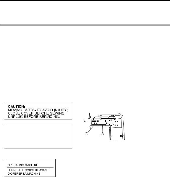
 CAUTION
When threading or replacing needle, the main power and light switch of the machine must be switched off or the plug must be removed from the socket-outlet.
When the machine is not in use, it is recommended that the electric supply plug is disconnected from the wall socket to avoid any possible hazards.
Notes on the motor
-The maximum operating speed of this sewing machine is 1,000 stitches per minute, which is quite fast compared to the normal operating speed of 300 to 800 stitches per minute for the ordinary sewing machine.
-The bearings in the motor are made of a special material (oil-impregnated alloy mounted in felt heat-treated with oil) that enables them to withstand long hours of continuous operation.
-Continuous operation of the sewing machine can cause heat to build in the motor area, but not enough to adversely affect its performance.
It is important to keep fabric and paper away from the air openings on the back and sides of the machine so air can get to these openings.
-When the motor is running, sparks can be seen through the air openings in the motor bracket on the side opposite the handwheel. These sparks are produced by the carbon brushes and the commutator, and are part of the machines normal operation.
WARNING LABELS (for complying with UL and CSA requirements) The following warning labels are on the machine.
Be sure to observe the precautions described in the labels.
Caution (U.S.A. and CANADA only)
1
Label locations
2 AVERTISSEMENT:
PARTIES EN MOUVEMENT. POUR ÉVITER TOUTE BLESSURE: FERMER LE CAPOT AVANT DE COUDRE.
DÉBRANCHER AVANT ENTRETIEN.
Face plate sticker (U.S.A. and CANADA only)
3 


2

Contents |
|
Chapter 1 : NAMES OF PARTS AND THEIR FUNCTIONS.................................................... |
4 |
Machine (Cover stitch model) (Product code: 884-B30) ..................................................... |
4 |
Accessories (Cover stitch model) ....................................................................................... |
5 |
Machine (Top cover stitch model) (Product code: 884-B31) ............................................... |
6 |
Accessories (Top cover stitch model) ................................................................................. |
7 |
Powering the machine......................................................................................................... |
8 |
Turning direction of handwheel ........................................................................................... |
8 |
Opening/Closing front cover ............................................................................................... |
8 |
Attaching/Removing a presser foot..................................................................................... |
8 |
Free-arm sewing (removing the bed extension).................................................................. |
9 |
Looper thread tension adjustment lever.............................................................................. |
9 |
Stitch length ........................................................................................................................ |
10 |
Differential feed................................................................................................................... |
10 |
Adjusting the presser foot pressure .................................................................................... |
11 |
Adjusting the tension dials .................................................................................................. |
11 |
Needle ................................................................................................................................ |
12 |
Removing/Installing the needle........................................................................................... |
12 |
Chapter 2 : PREPARATION BEFORE THREADING .............................................................. |
13 |
Thread tree ......................................................................................................................... |
13 |
Using the thread spool cap ................................................................................................. |
13 |
Spool mat............................................................................................................................ |
13 |
Using the spool mat ............................................................................................................ |
13 |
Using the thread net ........................................................................................................... |
14 |
Before threading ................................................................................................................. |
14 |
Chapter 3 : THREADING (Cover stitch model) ..................................................................... |
15 |
Threading the looper........................................................................................................... |
15 |
Threading the needles ........................................................................................................ |
16 |
Chapter 4 : THREADING (Top cover stitch model) .............................................................. |
17 |
Threading the looper........................................................................................................... |
17 |
Threading the needles ........................................................................................................ |
18 |
Attaching/Removing the top cover spreader and top cover thread guide ........................... |
19 |
Threading the top cover spreader....................................................................................... |
20 |
Chapter 5 : TYPE OF STITCHES COMPARISON CHART ..................................................... |
21 |
Chapter 6 : SEWING ............................................................................................................... |
24 |
Sewing fl at fabric (for example, trial sewing)....................................................................... |
24 |
Removing the fabric from the machine (Cover stitch model) .............................................. |
24 |
Removing the fabric from the machine (Top cover stitch model) ........................................ |
25 |
Sewing a cover stitch .......................................................................................................... |
27 |
Sewing tubular garments (for example, cuffs)..................................................................... |
27 |
Stabilizing the beginning and end of stitching..................................................................... |
28 |
Chapter 7 : TROUBLESHOOTING.......................................................................................... |
29 |
Chapter 8 : MAINTENANCE ................................................................................................... |
30 |
Cleaning.............................................................................................................................. |
30 |
SPECIFICATIONS.................................................................................................................... |
31 |
English
3

CHAPTER 1
NAMES OF PARTS AND THEIR FUNCTIONS
Machine (Cover stitch model) (Product code: 884-B30)
1 |
|
|
|
|
|
|
|
|
9 |
0 |
|
|
|
|
|
|
A |
|
|
|
2 |
|
|
B |
|
|
|
|
|
|
|
|
|
|
|
|
|
C |
|
|
|
3 |
|
|
|
|
|
|
4 |
|
|
|
|
|
|
5 |
|
|
|
|
|
|
|
|
|
|
E |
|
N |
|
|
|
|
F |
|
|
6 |
|
|
D |
|
|
|
|
|
|
|
G |
|
|
7 |
|
8 |
|
|
|
|
|
|
|
|
|
|
|
|
|
|
|
H |
|
|
|
Inside of the front cover |
|
|
|
||
|
|
|
|
I |
|
|
|
R |
Q |
|
|
|
|
|
|
|
J |
|
|
|
|
|
|
|
|
|
|
|
|
|
P |
K |
|
|
|
|
|
|
|
|
|
|
S |
|
|
|
L |
O |
|
|
|
|
|
|
|
|
|
|
|
|
|
M |
<C> |
|
|
|
|
|
|
<B> T |
<A> |
1Thread tree
2Presser foot pressure adjustment screw
3Thread take-up cover
4Thread cutter
5Material plate cover
6Needles
7Bed extension
8Presser foot
9Left needle thread tension dial
0 Center needle thread tension dial
ARight needle thread tension dial
BLooper thread tension dial
CPresser foot lever
DFront cover
EThread guide
FSpool pin
GSpool cushion
HSpool support
IStitch length adjustment dial
JDifferential feed ratio adjustment dial
KHandwheel
LMain power and light switch
MFoot controller socket
NHandle
OAir openings
Inside of the front cover
PLooper thread tension adjustment lever
QLooper thread take-up
RLooper
SLooper release lever
t Front cover compartment
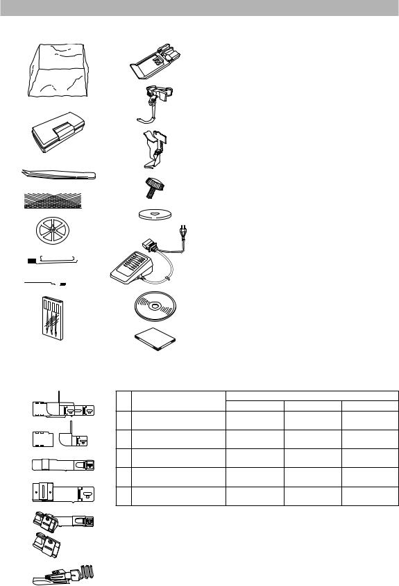
You can store the included accessories in this front cover compartment. <A>: Needle set, <B>: Tweezers, <C>: Hexagonal driver
4
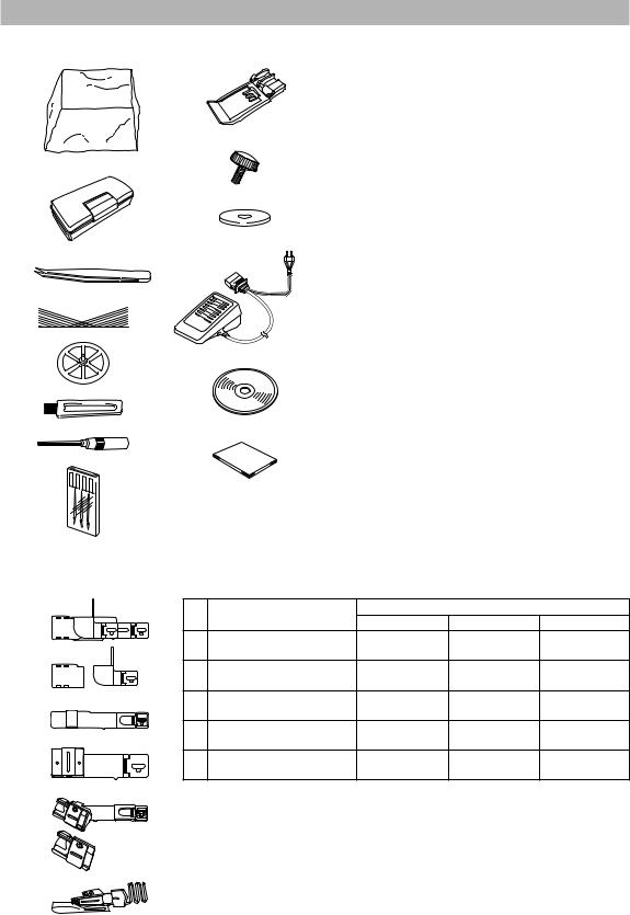
Accessories (Cover stitch model)
Included accessory
1 |
9 |
|
0 |
2
A
B
3
4 


5
|
C |
6 |
|
7 |
D |
8 |
|
Optional accessory
|
|
|
|
|
No. |
Part Name |
Part Code |
|
|
1 |
Soft cover |
XB3264001 |
|
English |
4 |
Thread net (4) |
X75904000 |
|
|
2 |
Accessory box |
XB3291001 |
|
|
3 |
Tweezers |
XB1618001 |
|
|
|
|
|
|
|
5 |
Thread spool cap (4) |
X77260000 |
|
|
6 |
Cleaning brush |
X75906001 |
|
|
|
|
|
|
|
7 |
Hexagonal driver |
XB0393001 |
|
|
8 |
Needle set (130/705H) |
XB1216001 |
|
|
#90: 3 pcs. |
|
|
||
9 |
Clear foot |
XB3361001 |
|
|
0 |
Attachment screw (2) |
XB3292001 |
|
|
A |
Spool mat (4) |
XB1218001 |
|
|
|
|
XC7359021 (120V Area) |
|
|
|
|
XB3112001 (230V Area) |
|
|
|
|
XB3134001 (U.K.) |
|
|
|
|
XB3200001 (Argentina) |
|
|
B |
Foot controller |
XB3156001 (Korea) |
|
|
XB3255001 (China) |
|
|
||
|
|
|
|
|
|
|
XB3190001 |
|
|
|
|
(Australia, New Zealand) |
|
|
|
|
XF2826001 (Brazil 127V) |
|
|
|
|
XB3178001 (Brazil 220V) |
|
|
C |
Instruction DVD |
XB3301001 (NTSC) |
|
|
XB3305001 (PAL) |
|
|
||
|
|
|
|
|
D |
Operation Manual |
- |
|
|
When using the following accessories, use the presser foot included in the accessories.
E |
No. |
Product Name |
|
Part Code |
|
|
|
Americas |
Europe |
Others |
|||
|
|
|
||||
|
E Hemming set |
SA221CV |
SA221CV/ |
SA221CV |
||
|
XB2970-101 |
|||||
|
|
|
|
|
||
|
F Bias tape folder |
SA222CV |
SA222CV/ |
SA222CV |
||
|
XB2971-101 |
|||||
|
|
|
|
|
||
|
G |
Belt loop guide |
SA223CV |
SA223CV/ |
SA223CV |
|
F |
XB2972-101 |
|||||
|
|
|
|
|||
|
H Bias tape binding set |
SA230CV |
SA230CV/ |
SA230CVAP |
||
|
XB3387-001 |
|||||
G |
|
|
|
|
||
|
|
|
SA231CV/ |
|
||
|
I Dual function fold binder |
SA231CV |
SA231CVAP |
|||
|
XB3388-001 |
|||||
|
|
|
|
|
||
H
I
5
Machine (Top cover stitch model) (Product code: 884-B31)
a
k l
m
n
b
o
p
c
d
 e
e


q
f |
|
|
j |
|
h |
i |
|
g |
|
|
|
|
|
|
Inside of the front cover
U
T
S
V
<C>
<B> W |
<A> |
|
1Thread tree
2Presser foot pressure adjustment screw
3Thread take-up cover
4Thread cutter
5Material plate cover
6Needles
7Bed extension
8Presser foot
9Top cover spreader
0 Top cover thread guide
ALeft needle thread tension dial
BCenter needle thread tension dial
CRight needle thread tension dial
DTop cover thread tension dial
ELooper thread tension dial
FPresser foot lever
GFront cover
HThread guide
ISpool pin
H Q
I
J
K
L


M
N
O 


 R
R
P
JSpool cushion
KSpool support
LStitch length adjustment dial
MDifferential feed ratio adjustment dial
NHandwheel
OMain power and light switch
PFoot controller socket
QHandle
RAir openings
Inside of the front cover
S Looper thread tension adjustment lever t Looper thread take-up
ULooper
VLooper release lever
WFront cover compartment
You can store the included accessories in this front cover compartment. <A>: Needle set, <B>: Tweezers, <C>: Hexagonal driver
6
Accessories (Top cover stitch model)
Included accessory
1 9
0
2
A
3
B
4 

C
5
D
6 
 7
7 


E
8
F
Optional accessory
|
|
|
|
|
No. |
Part Name |
Part Code |
|
|
1 |
Soft cover |
XB3264001 |
|
English |
4 |
Thread net (5) |
X75904000 |
|
|
2 |
Accessory box |
XB3291001 |
|
|
3 |
Tweezers |
XB1618001 |
|
|
|
|
|
|
|
5 |
Thread spool cap (5) |
X77260000 |
|
|
6 |
Cleaning brush |
X75906001 |
|
|
|
|
|
|
|
7 |
Hexagonal driver |
XB0393001 |
|
|
8 |
Needle set (130/705H) |
XB1216001 |
|
|
#90: 3 pcs. |
|
|
||
9 |
Clear foot |
XB3361001 |
|
|
0 |
Top cover spreader |
XB3090001 |
|
|
A |
Top cover thread guide |
XB3105001 |
|
|
B |
Attachment screw (2) |
XB3292001 |
|
|
C |
Spool mat (5) |
XB1218001 |
|
|
|
|
XC7359021 (120V Area) |
|
|
|
|
XB3112001 (230V Area) |
|
|
|
|
XB3134001 (U.K.) |
|
|
|
|
XB3200001 (Argentina) |
|
|
D |
Foot controller |
XB3156001 (Korea) |
|
|
XB3255001 (China) |
|
|
||
|
|
|
|
|
|
|
XB3190001 |
|
|
|
|
(Australia, New Zealand) |
|
|
|
|
XF2826001 (Brazil 127V) |
|
|
|
|
XB3178001 (Brazil 220V) |
|
|
E |
Instruction DVD |
XB3301001 (NTSC) |
|
|
XB3305001 (PAL) |
|
|
||
|
|
|
|
|
F |
Operation Manual |
- |
|
|
When using the following accessories, use the presser foot included in the accessories.
G |
No. |
Product Name |
|
Part Code |
|
|
|
Americas |
Europe |
Others |
|||
|
|
|
||||
|
G Hemming set * |
SA221CV |
SA221CV/ |
SA221CV |
||
|
XB2970-101 |
|||||
|
|
|
|
|
||
|
H Bias tape folder |
SA222CV |
SA222CV/ |
SA222CV |
||
|
XB2971-101 |
|||||
|
|
|
|
|
||
H |
I |
Belt loop guide |
SA223CV |
SA223CV/ |
SA223CV |
|
XB2972-101 |
||||||
|
|
|
|
|||
|
J Bias tape binding set |
SA230CV |
SA230CV/ |
SA230CVAP |
||
I |
XB3387-001 |
|||||
|
|
|
|
|||
|
|
|
SA231CV/ |
|
||
|
K Dual function fold binder |
SA231CV |
SA231CVAP |
|||
|
XB3388-001 |
|||||
|
|
|
|
|
||
J |
* Can be used only with a cover stitch; cannot be used with a top cover stitch. |
|||||
K
7
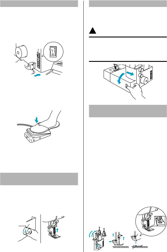
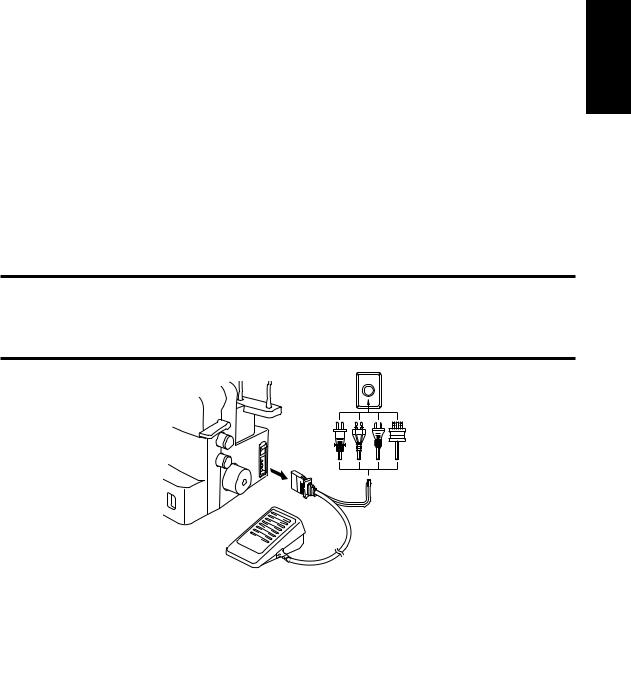
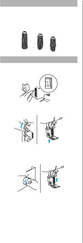
Powering the machine
Turning on the machine
1.Insert the three-pin plug into the socket on the lower-right side of the machine. Insert the power supply plug into a power outlet.
2.Turn the main power and light switch <A> to “I” mark (to “O” mark to turn off).
<A>
Operation
When the foot controller is pressed lightly, the machine runs at a low speed. As the foot controller is pressed further, the machine will increase speed. When the foot controller is released, the machine stops.
NOTE (For U.S.A. only):
Foot controller: Model KD-1902
This foot controller can be used on the machine with product code 884-B30 and 884-B31.
*The product code is shown on the machine rating plate.
Turning direction of
handwheel
The handwheel <A> turns in a counterclockwise direction (direction of arrow). This is the same direction as an ordinary home sewing machine. Move the needles to their highest positions by turning the handwheel so that the mark <B> on the handwheel is aligned with the line on the machine.
 <A>
<A>
<B>
8
Opening/Closing front cover
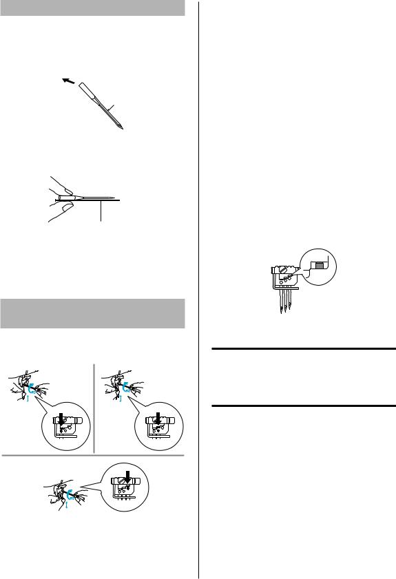
It is necessary to open the front cover when threading this machine. Slide it to the right 1, and then open it 2. After closing it, slide it to the left.
 CAUTION
For your safety, make sure that the front cover is closed when operating the machine.
Always turn off the machine before opening the front cover.
a
b
Attaching/Removing a
presser foot
1.Turn off the main power and light switch or disconnect the power supply plug.
2.Raise the presser foot lever 1.
3.Turn the handwheel 2 so that the line on the handwheel is aligned with the line on the
machine. (See “Turning direction of handwheel” in CHAPTER 1.)
4.Push the button on the presser foot holder 3 to release the standard presser foot.
5.Raise the presser foot farther by pushing the presser foot lever upward. Then, remove the presser foot and store it in a safe location.
6.Again, raise the presser foot farther by pushing the presser foot lever upward. Place the presser foot just under the presser foot holder <A> so that the groove in the bottom of the presser foot holder <B> is aligned with the bar on the top of the foot <C>, and then lower the presser foot lever to attach the foot 4.
d
|
|
|
|
<A> |
a |
|
a |
|
<B> |
|
b |
c |
b |
d |
|
|
|
||
|
|
|
|
<C> |
Free-arm sewing
(removing the bed extension)
Free-arm sewing enables tubular pieces to be sewn more easily.
1. Remove the bed extension.
1
1 Bed extension
NOTE:
Be careful not to lose the removed bed extension.
2.Position the fabric, and then start sewing. (See CHAPTER 5.)
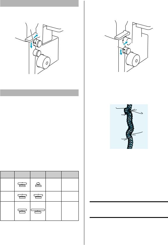
Looper thread tension
adjustment lever
With the looper thread tension adjustment lever, |
|
||
fi ne adjustments can be made to the looper thread |
|
||
tension. When sewing stretch fabric or with a small |
English |
||
stitch length, raise the lever to increase the tension |
|||
|
|||
of the looper thread. When sewing non-stretch |
|
||
fabric or with a large stitch length, lower the lever |
|
||
to reduce the tension of the looper thread. |
|
||
|
|
|
|
|
|
|
|
|
|
|
|

 1
1
2 <A>
<A>
1 Raise the lever to increase the tension of the looper thread. 2 Lower the lever to reduce the tension of the looper thread. <A> Looper thread tension adjustment lever
Non-stretch fabric such as serge
Reduce the tension of the looper thread.
Lever position: Center |
Lever position: Down |
Stretch fabric such as smooth knit
Increase the tension of the looper thread.
Lever position: Center |
Lever position: Up |
9
Stitch length
The normal stitch length setting is 3 mm. To change the stitch length, turn the stitch length
adjustment |
of the machine. |
|
<A> |
|
a |
|
b |
1 Shorten the stitch length to a minimum of 2 mm (5/64 inch). 2 Lengthen the stitch to a maximum of 4 mm (5/32 inch). <A> Selection mark
Differential feed
There are two sets of feed dogs under the presser foot to move the fabric through the machine. The differential feed controls the movement of both the front and the rear feed dogs. When set at 1, the feed dogs are moving at the same speed (ratio of 1). When the differential feed ratio is set at less than 1, the front feed dogs move less than the rear feed dogs, stretching the fabric as it is sewn. This is effective on lightweight fabric that may pucker. When the differential feed ratio is set at greater than 1, the front feed dogs move more than the rear feed dogs, gathering the fabric as it is sewn. This function assists in removing rippling when sewing stretch fabrics.
Differential feed adjustment
Feed ratio Main feed |
Differential |
Effect |
Application |
(rear) |
feed (front) |
|
|
|
|
Material is |
Prevents thin |
Less than |
|
pulled tight. |
materials |
1.0 |
|
|
from |
|
|
|
puckering |
|
|
Without |
Normal |
1.0 |
|
differential |
sewing |
|
|
feed. |
|
|
|
Material is |
Prevents |
|
|
gathered |
stretch |
Greater |
|
or pushed |
materials |
than 1.0 |
|
together. |
from |
|
|
|
stretching or |
|
|
|
puckering |
The normal setting is 1.0 on the differential feed adjustment dial.
To adjust the differential feed, turn the dial on the lower-right side of the machine.
a
<A>
b
1 Less than 1.0
2 Greater than 1.0 <A> Selection mark
An example
When stretch material is sewn without using the differential feed, the fabric will be wavy.
To get a smooth finish, adjust the feed ratio from 1.0 toward 2.0.
(The feed ratio required depends on the elasticity of the material.)
The more elastic the material, the further toward 2.0 the differential feed ratio should be set. Test sew with a scrap of the fabric to fi nd the correct adjustment.
 CAUTION
When sewing thick non-stretchable material such as denim, do not use the differential feed as it may damage the fabric.
10
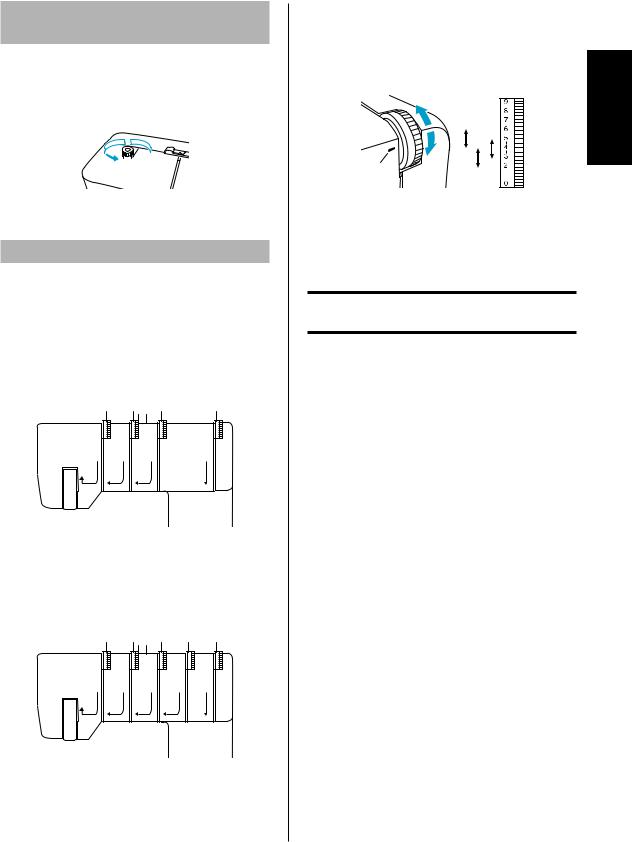
Adjusting the presser
foot pressure
Turn the pressure adjustment screw on the left of the top of the machine. Refer to the value on the screw to make the adjustment.
The normal setting is “2”.
a


 b
b
<A>
1 Less pressure
2 More pressure <A> Selection mark
Adjusting the tension dials
There is a thread tension dial for each needle thread, the looper thread and the top cover thread. The correct thread tension may vary according to the type and thickness of the fabric and the type of thread used. Thread tension adjustments may be necessary for any change in sewing materials.
Cover stitch model
1 |
2 |
3 |
4 |
|
|
|
|
4 |
4 |
4 |
4 |
1 The tension dial marked in yellow is for the left needle thread. 2 The tension dial marked in green is for the center needle
thread.
3 The tension dial marked in pink is for the right needle thread. 4 The tension dial marked in blue is for the looper thread.
Top cover stitch model
1 2 3 4 5
|
|
|
|
|
4 |
4 |
4 |
4 |
4 |
1 The tension dial marked in yellow is for the left needle thread. 2 The tension dial marked in green is for the center needle
thread.
3 The tension dial marked in pink is for the right needle thread. 4 The tension dial marked in purple is for the top cover thread. 5 The tension dial marked in blue is for the looper thread.
Tension control
Sewing is possible at position “4” for most circumstances. (Standard: SPAN #60)
If the stitch quality is insuffi cient, select a different tension setting.
5
|
1 |
4 |
3 |
|
|
|
2 |
|
3 |
<A>
1 For heavy tension: 4 to 6
2 For light tension: 4 to 2
3 For medium tension: 5 to 3 <A> Tension selection mark
 CAUTION
Make sure that the thread is properly seated in the tension discs.
English
11
Needle
This machine uses a standard home sewing machine needle.
The recommended needle is 130/705H (#90).
Needle description
1 
 2
2
3
1 Back (fl at side)
2Front
3Groove
How to check the needle

 5
5
4
4Flat surface
5Place the needle on its flat side and check to see if the space is even.
NOTE:
Fabric damage can be reduced by using 130/705H SUK (#90) BALL POINT.
Removing/Installing
the needle
<A> Removing/installing the left needle <B> Removing/installing the center needle <C> Removing/installing the right needle
<A> |
<B> |
1 |
1 |
2 |
2 |
<C>
1
2 |
1Tighten
2Loosen
To remove:
1.Turn off the main power and light switch.
2.Turn the handwheel so that the line on the handwheel is aligned with the line on the machine. (See “Turning direction of handwheel” in CHAPTER 1.)
3.Loosen the corresponding needle set screw by turning it with the included hexagonal driver toward 2 in the illustration, and then remove the needle.
To install:
1.Turn off the main power and light switch.
2.Turn the handwheel so that the line on the handwheel is aligned with the line on the machine.
3.Hold the needle with its fl at side away from you and insert it up as far as it will go.
4.Tighten the needle set screw securely by turning it with turning the included hexagonal driver toward 1 in the illustration.
NOTE:
Be sure to insert the needles all the way.
 CAUTION
Always be sure to turn off the power before removing/inserting the needle.
Do not drop the needle and needle set screw in the machine, otherwise it may be damaged.
12
CHAPTER 2
PREPARATION BEFORE THREADING
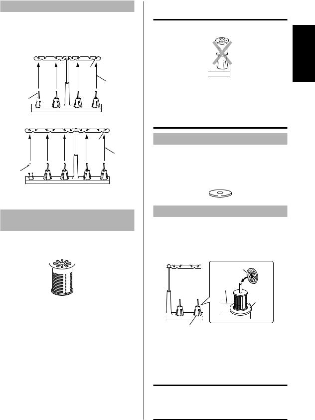
Thread tree
Raise the telescoping thread tree to its highest position. Make sure that the thread holders are in alignment above the spool pins as illustrated below.
Cover stitch model
1
3
2 

Top cover stitch model
1
3
2 

1 Thread holder on thread tree
2 Spool pin
3 Correct position
Using the thread
spool cap
When using sewing thread spools, the thread spool cap should be used as illustrated below. Make sure that the spool notch is on the bottom.
 1
1
1 Thread spool cap
 CAUTION
Before using a thread spool, be sure to remove the spool cushion.
Before using loosely spun nylon thread, be sure to install the spool cushion.
If the thread spool cap is not fully pushed down, the thread may become entangled on the spool pin or the needle may bend or break.
Spool mat
When using thread spools or loosely spun thread that easily slips off the spool, place this mat under the spool.
This prevents the thread from becoming entangled on the spool pin.
Using the spool mat
1.Remove the spool cushion, and then place the spool mat on the spool pin.
2.Place the thread spool (with the spool notch at the bottom) on the spool pin, and then place the thread spool cap on top and fully push it down.
2
3
4
1
1 Spool cushion
2 Thread spool cap
3 Spool support
4 Spool mat
 CAUTION
If the thread spool cap is not fully pushed down against the thread spool, the thread may become entangled on the spool pin or the needle may bend or break.
English
13
Using the thread net
If you are sewing with loosely spun nylon thread, we recommend that you cover the spool with the included net in order to prevent the thread from slipping off the spool.
Adapt the net to the shape of the spool.
Before threading
1.Turn off the main power and light switch for safety.
2.Raise the presser foot using the presser foot lever.
3.Turn the handwheel so that the line on the handwheel <A> is aligned with the line <B> on the machine. (See “Turning direction of handwheel” in CHAPTER 1.)
 <A>
<A>
<B>
14
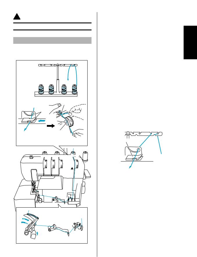
CHAPTER 3
THREADING (Cover stitch model)
 CAUTION
Before threading, turn off the machine for safety.
Threading the looper
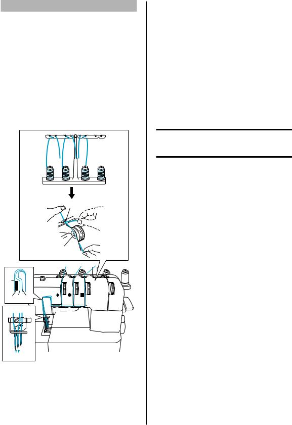
Run the thread in the sequence illustrated, following the blue line and the numbers next to each threading point.
2
1


 3 3
3 3 

A |
6 |
5 |
|
|
4 |
4


 3
3 


 4
4 


C
A |
B |
|
|
6 |
|
|
9 |
|
|
5 |
|
D |
|
|
|
|
: |
8 |
7 |
|
|
1.Open the front cover by sliding it to the right and guiding the top toward you.
2.Pull the thread off the spool and directly up through thread holder 1 and thread holder 2 on the thread tree, from back to front.
3.Pass the looper thread 3 as shown in the illustration.
4.Pass the thread through the tension disc 4 in the channel next to the tension dial marked with a blue c.
5.Guide the thread down the channel and through threading points 5-9, following the numerical order in the illustration.
6.After running the thread to 9, push the looper release lever 0 to move the looper to the right A, and then run the thread through B-C.
7.Pull about 10 cm (4 inch) of thread through the eye of the looper.
8.While pushing the looper D, return the looper to its original position.
9.Close the front cover.
NOTE:
When using thick thread, such as decorative thread, as the looper thread, run the thread as shown in the illustration.
A
Do not run the thread through A.
English
15
Threading the needles
Needle threads used by the various stitches
The triple cover stitch (three-needle, four-thread cover stitch) uses the left needle thread, center needle thread and right needle thread.
The two-needle, three-thread cover stitch (Wide) (6 mm (15/64 inch)) uses the left needle thread and right needle thread.
The two-needle, three-thread cover stitch (Narrow) (3 mm (1/8 inch)) uses the center needle thread and right needle thread.
The chain stitch uses the center needle thread and looper thread.
2 2 2
1  1
1  1
1


 333
333
|
F |
|
6 |
|
|
|
5 |
|
|
|
|
|
4 |
|
|
444 |
|
|
|
A |
|
3 3 |
3 |
|
4 |
4 |
4 |
|
|
|
|
|||
D B C |
666 |
|
|
|
|
|
|
|
|
7 77 |
5 |
5 |
5 |
|
8 88
E

999
ATo left needle
BTo center needle
CTo right needle
DBranching plate
EPull about 6 cm (about 2-1/2 inches) of thread through the eye of the needle.
999 Front to back
Threading the left needle
Run the thread in the sequence illustrated, following the yellow numbers and ¡ marks next to the threading points. (1-9)
Threading the center needle
Run the thread in the sequence illustrated, following the green numbers and z marks next to the threading points. (1-9)
Threading the right needle
Run the thread in the sequence illustrated, following the pink numbers and marks next to the threading points. (1-9)
 CAUTION
When threading the needles, always thread in the following order: left needle, center needle and right needle.
1.Pull the thread off the spool and directly up through thread holder 111 and thread holder 222 on the thread tree, from back to front.
2.Pass each thread through 333, shown in the illustration.
3.Pass the thread through the tension disc 444 in the channel next to the tension dial.
4.Guide the thread down the channel and across through threading points 555-888 next to the color marks, following the numerical order in the illustration.
5.Pass the thread through the eye of the needle, front to back.
16

CHAPTER 4
THREADING (Top cover stitch model)
 CAUTION
Before threading, turn off the machine for safety.
Threading the looper
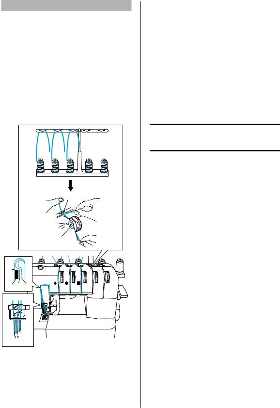
Run the thread in the sequence illustrated, following the blue line and the numbers next to each threading point.
2
1


 3 3
3 3 

A |
6 |
5 |
|
|
4 |
4


 3
3 


 4
4


C
A |
B |
|
|
9 |
6 |
||
|
|||
|
5 |
||
D |
|
||
|
|
: |
8 |
7 |
|
|
1.Open the front cover by sliding it to the right and guiding the top toward you.
2.Pull the thread off the spool and directly up through thread holder 1 and thread holder 2 on the thread tree, from back to front.
3.Pass the looper thread 3 as shown in the illustration.
4.Pass the thread through the tension disc 4 in the channel next to the tension dial marked with a blue c.
5.Guide the thread down the channel and through threading points 5-9, following the numerical order in the illustration.
6.After running the thread to 9, push the looper release lever 0 to move the looper to the right A, and then run the thread through B-C.
7.Pull about 10 cm (4 inch) of thread through the eye of the looper.
8.While pushing the looper D, return the looper to its original position.
9.Close the front cover.
NOTE:
When using thick thread, such as decorative thread, as the looper thread, run the thread as shown in the illustration.
A
Do not run the thread through A.
English
17
Threading the needles
Needle threads used by the various stitches
The triple cover stitch (three-needle, four-thread cover stitch) uses the left needle thread, center needle thread and right needle thread.
The two-needle, three-thread cover stitch (Wide) (6 mm (15/64 inch)) uses the left needle thread and right needle thread.
The two-needle, three-thread cover stitch (Narrow) (3 mm (1/8 inch)) uses the center needle thread and right needle thread.
The chain stitch uses the center needle thread and looper thread.
2 2 2
1  1
1  1
1 


 333
333
|
F |
|
6 |
|
|
|
5 |
|
|
|
|
|
4 |
|
|
444 |
|
|
|
A |
|
3 3 |
3 |
|
4 |
4 |
4 |
|
|
|
|
|||
D B C |
666 |
|
|
|
|
|
|
|
|
7 77 |
5 5 |
5 |
|
|
8 88
E

999
ATo left needle
BTo center needle
CTo right needle
DBranching plate
EPull about 6 cm (about 2-1/2 inches) of thread through the eye of the needle.
999 Front to back
Threading the left needle
Run the thread in the sequence illustrated, following the yellow numbers and ¡ marks next to the threading points. (1-9)
Threading the center needle
Run the thread in the sequence illustrated, following the green numbers and z marks next to the threading points. (1-9)
Threading the right needle
Run the thread in the sequence illustrated, following the pink numbers and marks next to the threading points. (1-9)
 CAUTION
When threading the needles, always thread in the following order: left needle, center needle and right needle.
1.Pull the thread off the spool and directly up through thread holder 111 and thread holder 222 on the thread tree, from back to front.
2.Pass each thread through 333, shown in the illustration.
3.Pass the thread through the tension disc 444 in the channel next to the tension dial.
4.Guide the thread down the channel and across through threading points 555-888 next to the color marks, following the numerical order in the illustration.
5.Pass the thread through the eye of the needle, front to back.
18
Attaching/Removing the top cover spreader and
top cover thread guide
Attaching the top cover spreader and top cover thread guide
1.Turn the handwheel so that the line on the handwheel <A> is aligned with the line <B> on the machine.
<B>
<A>
2.Squeeze the grip of the top cover spreader to spread the tips, and then, from the right side, clamp the mount of the top cover spreader onto the top cover drive shaft.
1
3

2
1 Grip of top cover spreader
2 Mount of top cover spreader
3 Top cover drive shaft
3.Insert the top cover thread guide into the slot in the top cover thread guide mount.


 5
5
4
4 Top cover thread guide
5 Slot
Removing the top cover spreader and top cover thread guide
1.Turn the handwheel so that the line on the handwheel is aligned with the line on the machine.
<B>
<A>
2.Press the lever on the top cover thread guide mount, and then remove the top cover thread guide.


 1
1 


 2
2
1Lever
2Top cover thread guide
3.Squeeze the grip of the top cover spreader to spread the tips, and then remove the mount of the top cover spreader from the top cover drive shaft.
5

4 3
3 Grip of top cover spreader
4 Mount of top cover spreader
5 Top cover drive shaft
English
19
 Loading...