


EN Added Features of Version 1.7
FR Fonctions supplémentaires de la version 1.7
ES Características añadidas de la Versión 1.7
PT Recursos adicionados da Versão 1.7
Upgraded Operational Features
Grouping/Ungrouping Patterns
Multiple patterns selected in the layout editing screen can be combined into a single group, or that group can be separated into the individual patterns. (Under some conditions, it may not be possible to ungroup patterns. For the conditions where patterns cannot be ungrouped, refer to page 2.)
 Memo
Memo
•Because of changes made to the function, the function name “Unifying” (which unifies patterns), mentioned in the Operation Manual, has been changed to “Group/Ungroup”.
■Grouping Patterns
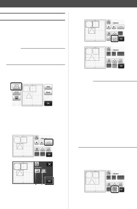
aTouch  in the pattern layout screen.
X The layout editing screen appears.
bTouch  , select the patterns to be grouped, and then touch the “OK” key.
•For details on selecting multiple patterns, refer to “Selecting Multiple Patterns” in the Operation Manual.
a b
aSelects the patterns in the selection area.
bSelects all patterns in the layout.
cTouch  in the layout editing screen.
XAll of the selected patterns are grouped. (The color of the key changed.)
 Memo
Memo
•The key color indicates how the selected patterns are grouped.
- : Two or more patterns are selected and can be grouped. When the key is touched, it appears as
  .
.
- : The patterns are grouped. (The color of the key changed.) When the key is touched, it appears as
  .
.
- : Since two or more patterns are not selected, patterns cannot be grouped.
•Patterns cannot be grouped under the following conditions.
-There is not enough of the machine’s memory available.
-A test pattern is included.
-Patterns with and without seam allowances have been selected.
■Ungrouping Patterns
aSelect grouped patterns in the layout editing screen, and then touch  .
.
1

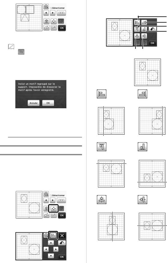
cAlign the patterns.
• The patterns are aligned depending on the key that is touched, as described below.
a
b c
d
XThe selected patterns are ungrouped. (The color of the key changed.)
 Memo
Memo
• If |
appears when patterns are selected, |
e f |
|
||
the patterns can be ungrouped. |
|
|
•Grouped patterns are saved as one pattern. When the saved pattern is recalled, it cannot be ungrouped. When saving a pattern that
contains grouped patterns, the following |
Original |
message appears. |
|
a b
Left |
Right |
•Patterns cannot be ungrouped under the following conditions.
-The number of patterns after being ungrouped exceeds the maximum number of patterns possible.
-The pattern was retrieved from the resume memory after an auto shutdown.
c d
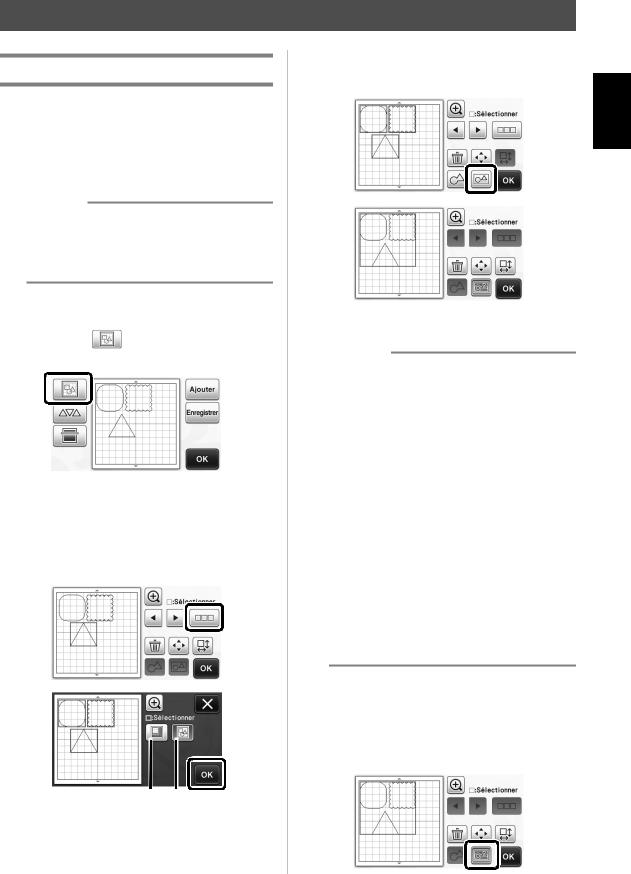
Aligning Patterns
Top |
Bottom |
Multiple patterns can be selected and aligned based on their positions or heights.
aSelect two or more patterns, and then touch
 .
.
• For details on selecting multiple patterns, refer to the Operation Manual.
e f
Center |
Middle |
bTouch  .
.
English
2
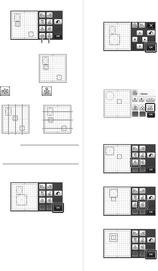
•If three or more patterns were selected, they can be distributed horizontally (g) or vertically (h).
g h
Original
g h
Distribute horizontally |
Distribute vertically |
 Note
Note
•When patterns are distributed, they may extend out the mat. Adjust the pattern positions according to the message instructions.
dTouch the “OK” key to return to the pattern moving screen.
eTouch the “OK” key to apply the pattern arrangement.
•Touch  to return to the layout editing screen without applying the pattern arrangement.
■ Centering Two or More Patterns
aAdd two circle patterns, and then change the size of one.
•For details on resizing patterns, refer to “Layout Editing Functions” in the Operation Manual.
bTouch  , then
  . The screen shown below appears. After touching
  and
and  to align the patterns, touch the “OK” key.
Ð
Ð
X The patterns are arranged.
3

Specifying “Blade Adjustment Area”
Before cutting out a pattern, this machine performs an automatic blade adjustment, which adjusts the direction of the blade outside of the adhesive area of the mat. A “Blade Adjustment Area” setting for this operation can be selected.
Before cutting, the machine will perform an automatic blade adjustment in a random location within the selected area.
Blade adjustment is not performed in areas that are not selected.
 Memo
Memo
•The blade adjustment may leave cutting traces in the mat, but this should not affect the quality of the blade or mat.
•When replacing the blade and inserting it into the blade slot of the holder, the direction in which the blade is inserted does not affect the resulting cut. During automatic blade adjustment, the direction of the blade will be adjusted as necessary.
aTouch  beside “Blade Adjustment Area” on page 4 of the settings screen.
bTouch  or
or  to select the blade adjustment area, and then touch the “OK” key.
•With each press of the left or right arrow key, the size of the blade adjustment area changes by 1/4.
 1 2
1 2  3
3  4
4 
a1/4
b2/4
c3/4
dEntire area
 Note
Note
•So that blade adjustment is not performed multiple times in the same location, we recommend that “Blade Adjustment Area” be set to the entire area.
Additional Symbols and Special
Characters
The following symbols and special characters have been added to the character patterns.
English
4

Importing Designs
Importable File Formats
In addition to the FCM format, files in the following formats can be imported into the machine.
•SVG (Scalable Vector Graphics: vector image format for describing two-dimensional graphics) format. “.svg” data is displayed in the pattern list screen by file name (the actual image cannot be displayed).
 Memo
Memo
•The imported vector graphics will appear in the edit screen after they have been converted. This feature allows you to import only vector data. Image, text, width of the line, gradient, opacity, and any other styles or attributes of line will not be imported.
Error Messages |
Causes / Solutions |
|
|
|
|
Since the shape was larger than the mat, it was reduced in |
If the pattern in the imported SVG file is larger than the mat, |
|
the pattern will be reduced to fit the size of the mat. If |
||
size when imported. |
necessary, in the software used to create the SVG file, edit |
|
|
the pattern to fit the size of the mat. |
|
|
|
|
Some shapes could not be converted. |
The imported SVG data contains data that cannot be |
|
converted, such as images or text. All other data was read as |
||
|
cutting line data. |
|
|
|
|
The data could not be imported. |
The message appears when an SVG file contains 301 or |
|
more patterns. In the software used to create the SVG file, |
||
There are too many patterns. |
||
reduce the number of patterns. |
||
|
||
|
|
|
The data is too complicated to be imported. |
SVG files containing a complicated pattern cannot be |
|
imported. In the software used to create the SVG file, simplify |
||
|
the pattern. |
|
|
|
|
There are no patterns that can be detected. |
The imported SVG data contains data that cannot be |
|
converted, such as images or text. |
||
|
||
|
|
5

Color recognition mode has been added to the “Direct Cut” and “Scan to Cut Data” modes.
For “SCANNING FOR CUTTING (Direct Cut)” and “CREATING CUTTING DATA (Scan to Cut Data)” in Chapter 4, “SCANNING FUNCTIONS”, of the Operation Manual, refer to the following.
SCANNING FOR CUTTING (Direct Cut)
A printed image (paper/sticker), stamped paper or an original hand-drawn illustration can be scanned and its outline can be cut out or drawn. This is useful for scanning images for paper crafts, then cutting them out.
Tutorial 1 - Scanning and Cutting
In this tutorial, we will scan an illustration drawn on paper, then cut around it.
■ Preparation
aPrepare the original.
When using the “Direct Cut” mode, use originals like those described below.
•Patterns that are clearly drawn, with no gradation, fading or blurriness
•Not using an extremely intricate design
bPress  to turn on the machine.
cInstall the cutting blade holder into the carriage of the machine.
■ Scanning
Depending on the color of the illustration, it can be scanned in grayscale or color recognition mode.
aTouch the “Scan” key in the home screen to select the scanning mode.
bSelect “Direct Cut” in the scanning mode selection screen.
X A message appears.
English
6
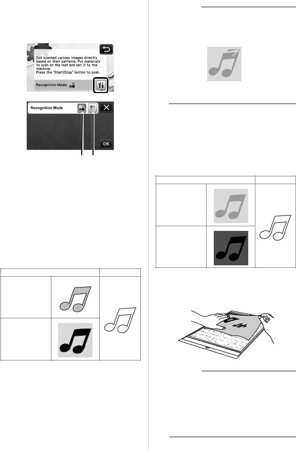
cSelect the scanning mode according to the material to be scanned.
•First, test with grayscale recognition mode. If the desired cutting data is not created, test with color recognition mode.
a b
aGrayscale recognition mode
The cutting data is created after the illustration is converted to grayscale.
Scanning in grayscale recognition mode is most appropriate for illustrations with clear outlines or distinct brightness differences. Processing is faster with this mode compared with the color recognition mode.
If there are adjacent objects of the same color after an illustration has been converted to grayscale, select the color recognition mode.
Examples of illustrations appropriate for grayscale recognition mode:
Example |
Result |
Outlines that are clear
Distinct difference in brightness between background and illustration
 Memo
Memo
•The edges of illustrations in a color of the same brightness as their background, as shown below, cannot be detected. In this case, use the color recognition mode.
 a
a
aBackground and illustration in colors with the same brightness.
bColor recognition mode
The cutting data is created without converting the illustration to grayscale. Creating data in this mode may take longer, depending on the pattern.
* The default scanning recognition setting is the grayscale recognition mode.
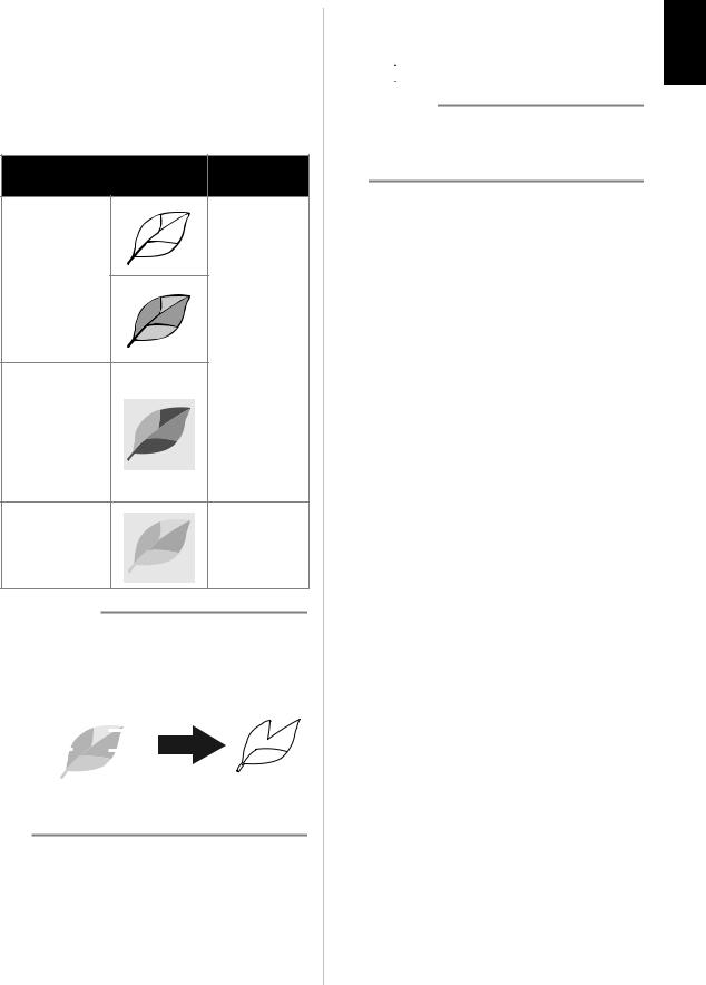
Examples of illustrations appropriate for color recognition mode:
Example |
Result |
Illustrations that are the same light color as the background
Illustrations that are the same dark color as the background
dAttach the original that will be scanned to the mat.
 Memo
Memo
•In “Direct Cut” mode, the scanning mat cannot be used.
•Depending on the machine model, the sizes of mats that can be used will differ. Check the “Maximum Scanning Area” under “Machine Information” on page 5 of the settings screen.
•Before attaching the material to the mat, use a corner of the adhesive side of the mat to test attaching it.
7
eWhile holding the mat level and lightly inserting it under the feed rollers on the left and
right sides of the feed slot, press  in the operation panel.
XThe “Start/Stop” button in the operation panel lights up.
fPress the “Start/Stop” button to start scanning.
■ Creating Cutting Data
The procedure for creating cutting data differs depending on the mode.
Grayscale recognition mode
aCheck the scanned image, and then touch the
“OK” key.
bIn the image trim screen, use the touch pen to
drag  to trim the image to the size to be imported.
XIf cutting lines are created, the outline of the scanned illustration will be black.
•Touch  to change the minimum object size that will be detected and the conversion threshold. For details, see “Adjusting Image Detection Levels” on page 17.
•Touch  or
or  to edit the imported cutting data. For details, see “Advanced Cutting Functions for “Direct Cut”” on page 9.
cTouch the “OK” key to confirm the trimmed area.
X Only the cutting lines appear.
English
dPress the “Start/Stop” button to start cutting.
Color recognition mode
aIn the image trim screen, use the touch pen to
drag  to trim the image to the size to be imported.
 Memo
Memo
•Trimming the image to the desired size can reduce the amount of time required to convert it to cutting data.
bTouch the “OK” key to confirm the trimmed area.
X The image is converted to cutting data.
8
cCheck the imported image in the image editing screen.
X The created cutting data appears as black lines.
 a
a  b
b
 c
c
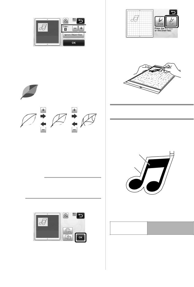
aIf the cutting lines were not correctly detected, change the number of colors to be detected. If a color that appears as a single color is detected as separate colors, reduce the number of colors. If adjacent colors with a similar brightness are detected as a single color, increase the number of colors.
original
bSmall unnecessary patterns (dotted lines, etc.) can be excluded from cutting data. For details, see “Specifying “Ignore Object Size”” on page 17.
cTouch the “OK” key to apply the settings. When the number of colors is changed, the “OK” key changes to the “Preview” key. After changing the number of colors, touch the “Preview” key to check the results.
 Memo
Memo
•When making a stamp, for example, the image may not be converted to cutting data if it contains a gradation or areas that are only partially filled with a color.
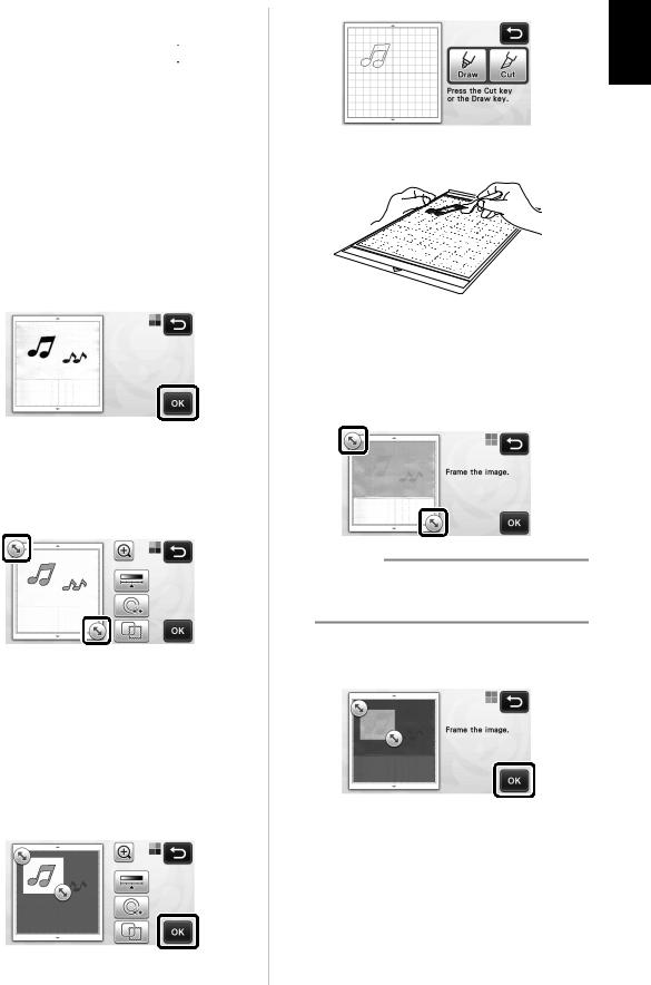
dTouch the “OK” key.
• Touch  or
or  to edit the imported
cutting data. For details, see “Advanced Cutting Functions for “Direct Cut”” on page 9.
X Only the cutting lines appear.
eTouch the “Cut” key.
XThe “Cut” key is highlighted, and the “Start/Stop” button in the operation panel lights up.
fPress the “Start/Stop” button to start cutting.
Advanced Cutting Functions for “Direct Cut”
■ Outline Distance
Use this function to cut while adding a margin around patterns. Specify the distance from the cutting line to the outline of the scanned image.
c
a
b
aPattern outline
bCutting line
cOutline distance
Available in the following screen
→Tutorial 1; Step c (page 8)
Image trim screen or Step d (page 9) in “Creating Cutting Data”
9
aTouch |
• With color recognition mode |
. |
|
• With grayscale recognition mode |
|
X The settings screen appears.
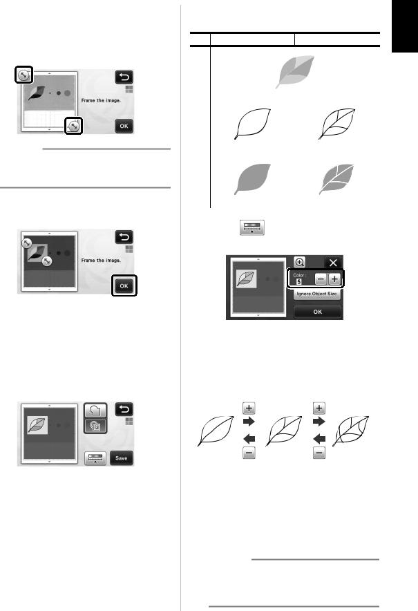
bSelect the shape of the cutting line.
• With color recognition mode
 a
a
d
 b
b
 c
c
X The setting screen appears. |
a Outlining |
|||
Touch this key to create a cutting line that follows the |
||||
|
|
|
||
bTouch |
or |
to change the setting. |
outline of the scanned image. |
|
b Frame Shape Scroll Keys |
||
Touch |
or |
to scroll up or down through the |
list of frames. |
|
|
c Framing |
|
|
Touch the key for the desired frame to add it to the |
||
scanned image and create a cutting line that follows |
||
its shape. |
|
|
• If there are multiple images, a frame can be |
||
specified for each image. |
||
■ Outlining and Framing |
|
||
Any shape can be specified as the cutting line for the |
|
||
scanned image. |
|
|
|
Available in the following screen |
|
||
|
|
|
|
|
|
→Tutorial 1; Step c (page 8) |
|
Image trim screen |
or Step d (page 9) in |
d Previewing |
|
|
|
“Creating Cutting Data” |
|
|
|
|
Display a preview of the image together with the |
|
|
|
|
aTouch |
. |
|
cutting line for the selected frame. |
|
|
||
• With grayscale recognition mode |
|
||
English
10

CREATING CUTTING DATA (Scan to Cut Data)
A printed pattern or image or an original hand-drawn illustration can be scanned, converted to cutting lines for cutting/drawing with this machine, then saved as data.
Tutorial 2- Creating Cutting Data
In this tutorial, we will save an illustration drawn on paper as cutting data.
■ Preparing the material
When using the “Scan to Cut Data” mode, use originals like those described below.
•Patterns that are clearly drawn, with no gradation, fading or blurriness
•Not using an extremely intricate design
■ Scanning
aTouch the “Scan” key in the home screen to select the scanning mode.
bSelect “Scan to Cut Data” in the scanning mode selection screen.
X A message appears.
cTouch  , select the scanning mode, and then touch the “OK” key.
•First, test with grayscale recognition mode. If the desired cutting data is not created, test with color recognition mode.
a b
aGrayscale recognition mode
The cutting data is created after the illustration is converted to grayscale. Scanning in grayscale recognition mode is most appropriate for illustrations with clear outlines or distinct brightness differences. Processing is faster with this mode compared with the color recognition mode.
If there are adjacent objects of the same color after an illustration has been converted to grayscale, select the color recognition mode.
11
bColor recognition mode
The cutting data is created without converting the illustration to grayscale.
Creating data in this mode may take some time. * The default color recognition setting is the
grayscale recognition mode.
Examples of illustrations appropriate for recognition mode:
Recommended Example recognition
mode
Outlines that are clear
Grayscale recognition mode
•Distinct difference in brightness between background and illustration
•Different brightness of adjacent colors
•Similar
brightness of
adjacent colors Color recognition mode
 Memo
Memo
•The edges of adjacent colors with the same brightness, as shown below, cannot be detected. In this case, use the color recognition mode.
a |
|
|
|
|
|
|
a |
|
|
|
|
|
b |
|
|
|
|
|
||
|
|
|
|
|
||
c |
|
|
|
|
|
d |
|
|
|
|
|
||
|
|
|
|
|
|
|
a“a” and “b” as well as “c” and “d” have the same brightness.
dAttach the original to the mat, and then load the mat into the feed slot.
•Lightly insert the mat into the feed slot, and press in
 the operation panel.
 Memo
Memo
•Depending on the machine model, the sizes of mats that can be used will differ. Check the “Maximum Scanning Area” under “Machine Information” on page 5 of the settings screen.
ePress the “Start/Stop” button to start scanning.
XWhen scanning is finished, the scanned image appears in the screen.
English
12

■ Creating Cutting Data
The procedure for creating cutting data differs depending on the mode.
Grayscale recognition mode
aSelect the cutting line type in the image editing screen.
The image shape is detected and cutting lines are created based on one of three standards. For this
example, touch  to create cutting lines using region detection.
 a
a
 b
b
 c
c
aOutline detection
If you wish to cut/draw along the outline of an image, select this option to convert the outline of the image to a cutting line. This is useful for saving as data an illustration drawn for an appliqué.
bRegion detection
Select this option to detect the colored portions of an image as regions and create a cutting line around each region. Cutouts can be created using thick hand-drawn lines, such as borderlines of images or text illustrations. This option allows you to use not only cut-out patterns but the material from which portions are cut out, such as lace.
cLine detection (Grayscale recognition mode only)
Select this option to detect the center of lines and convert them to a cutting line. This is useful for detecting patterns consisting of multiple pieces and creating cutting lines for each piece.
 Memo
Memo
•Lines thicker than 1.5 mm will not be detected as lines.
Difference in cutting lines depending on detection standard
Example 1
|
a Outline |
b Region |
c Line |
|
detection |
detection |
detection |
Original |
|
|
|
Cutting |
lines |
|
|
Finished project |
after cutting |
|
|
Example 2 |
|
|
|
|
a Outline |
b Region |
c Line |
|
detection |
detection |
detection |
Original |
|
|
|
Cutting |
lines |
|
Does not apply |
|
|
|
|
|
|
|
since there are |
projectFinished |
cuttingafter |
|
no outlines for |
|
each color in |
||
|
|
|
|
|
|
|
the original. |
bUse the touch pen to touch  and drag it around the screen to trim the cutting lines to be saved as data, and then touch the “Save” key.
• Touch  to change the minimum object size
that will be detected and the conversion threshold. For details, see “Adjusting Image Detection Levels” on page 17.
13
Color recognition mode
aIn the image trim screen, use the touch pen to
drag  to trim the image to the size to be imported.
 Memo
Memo
•Trimming the image to the desired size can reduce the amount of time required to convert it to cutting data.
bTouch the “OK” key to confirm the trimmed area.
cSelect the detection standard in the image editing screen.
The image shape is detected and cutting lines are created based on one of two standards. For this
example, touch  to create cutting lines using
region detection.
For details on the detection standards, see step a in “Grayscale recognition mode” on page 13.
 a
a
 b
b
aOutline detection
bRegion detection
Difference in cutting lines depending on detection standard
a Outline detection b Region detection
Original |
|
|
|
|
|
|
|
||
|
|
|
|
|
|
|
|
|
|
|
|
|
|
|
|
|
|
|
|
Cutting |
|
|
|
|
|
|
|
|
|
lines |
|
|
|
|
|
|
|
|
|
|
|
|
|
|
|
|
|
|
|
|
|
|
|
|
|
|
|
|
|
Finished project |
after cutting |
|
|
|
|
|
|
|
|
|
|
|
|
|
|
|
|
|
|
|
• Touch |
to change the number of colors |
|||||||
and the minimum object size that will be detected.
 a
a
 b
b
 c
c
aIf the cutting lines were not correctly detected, change the number of colors to be detected. If a color that appears as a single color is detected as separate colors, reduce the number of colors. If adjacent colors with a similar brightness are detected as a single color, increase the number of colors.
bSmall unnecessary patterns (dotted lines, etc.) can be excluded from cutting data. For details, see “Specifying “Ignore Object Size”” on page 17.
cTouch the “OK” key to apply the settings. When the number of colors is changed, the “OK” key changes to the “Preview” key. After changing the number of colors, touch the “Preview” key to check the results.
 Memo
Memo
•When making a stamp, for example, the image may not be converted to cutting data if it contains a gradation or areas that are only partially filled with a color.
English
14

■ Saving Data
aSelect the destination where the data will be saved.
Select the desired location. For this example, select the machine.
a
 b
b
aMachine
bUSB flash drive
XTouching a key starts saving the data. When the data has been saved, the following message appears.
bTouch the “OK” key to finish saving the data.
XThe destination memory selection screen appears again.
cPress  in the operation panel to feed out
the mat, and then peel off the original from the mat.
■ Recalling Cutting Data
Saved cutting data can be recalled for cutting.
aAttach the material for cutting to the mat, and then load the mat.
•For details on attaching the material, see “Mat and Cutting Blade Combinations” on page 12 of the Operation Manual.
bRecall the saved cutting data.
•For details on recalling data, follow the procedure under “Recalling” on page 41 of the Operation Manual.
X A preview of the pattern layout appears.
cEdit the cutting data as necessary, and then cut or draw.
15
 Memo
Memo
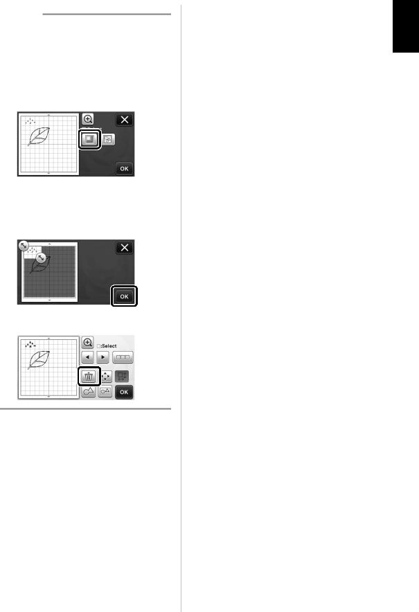
•Small spots and unwanted lines created during scanning can be deleted after a scanned image is converted to cutting data.
XAfter recalling the cutting data into the pattern layout screen, use the editing functions for selecting the spots to delete.
For details on the function, see “Specifying the Selection Area” on page 32 of the Operation Manual.
b
 a
a
aTouch for selecting multiple patterns in the specified area.
bUnwanted spots and lines
XSpecify the area of the unwanted spots, and then touch the “OK” key.
X Touch  to delete all of the selected spots.
English
16
Adjusting Image Detection Levels
The output levels of the scanned image data can be adjusted.
Available in the following screen
→Tutorial 2; Step a (page 13)
Image editing screen or Step c (page 14) in “Creating Cutting Data”
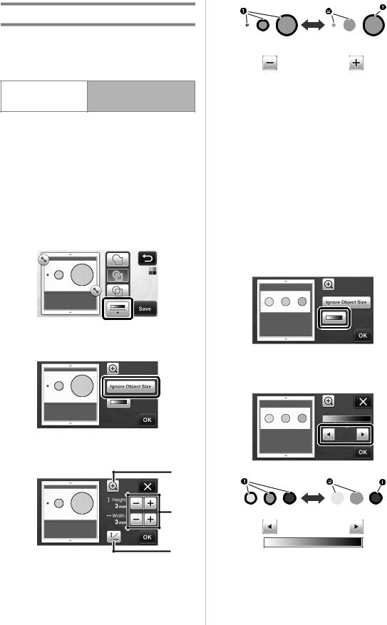
■ Specifying “Ignore Object Size”
Small unnecessary patterns (dotted lines, etc.) can be excluded from cutting data. In the following example, we will scan three images of different sizes (4 mm, 40 mm, 100 mm). This example describes the procedure using the grayscale recognition mode screen of the “Scan to Cut Data” mode.
aSelect one of the detection options, and then
touch  to display the function selection screen.
bTouch “Ignore Object Size” to display the setting screen.
cSpecify an object size smaller than which is not to be converted to cutting lines.
a
b |
c
aMagnifying
bSize Adjustment Keys
cLocking/Unlocking the Aspect Ratio
17
1 Cutting line created
2 No cutting line created
XTouch the “OK” key to apply the settings. Touch
 to return to the previous screen without applying the settings.
■Setting Image Detection Level (Grayscale recognition mode only)
Convert an image with a gradation or shading to a twotone (black and white) image, and then create cutting lines for that image. The image detection level (threshold) can be specified.
In the following example, we will scan three images of different tones (light, medium, dark).
aTouch  in the function selection screen to display the setting screen.
bSpecify the threshold for converting an image to a two-tone image using  and
and  .
.
1 Cutting line created
2 No cutting line created
XTouch the “OK” key to apply the settings. Touch
 to return to the previous screen without applying the settings.
Fonctions opérationnelles mises à niveau
Regroupement/Dissociation de motifs
Il est possible de combiner plusieurs motifs sélectionnés dans l'écran de disposition des motifs pour ne former qu'un seul groupe, et de diviser ce groupe pour retrouver les différents motifs qui le composent.
(Il est parfois impossible de séparer les motifs. Dans ce cas, reportez-vous à la page 2.)
 Mémo
Mémo
•Étant donné que des modifications ont été apportées à la fonction « Assemblage » (qui permet d'assembler des motifs) apparaissant dans le manuel d’instructions, cette fonction s'appelle désormais « Regrouper/Dissocier ».
■Regroupement de motifs
aAppuyez sur |
dans l'écran de disposition |
des motifs. |
|
X L'écran de modification de la disposition s'affiche.
bAppuyez sur  , sélectionnez les motifs à regrouper, puis appuyez sur la touche « OK ».
•Pour plus de détails sur la sélection de plusieurs motifs, reportez-vous à la section « Sélection de plusieurs motifs » dans le manuel d'instructions.
a b
aPermet de sélectionner les motifs dans la zone de sélection.
bPermet de sélectionner tous les motifs de l'aperçu.
cAppuyez sur  dans l'écran de modification de la disposition.
XTous les motifs sélectionnés sont regroupés. (La touche change de couleur.)
 Mémo
Mémo
•La couleur de la touche indique de quelle manière les motifs sélectionnés sont regroupés.
- : Deux motifs minimum sont sélectionnés et peuvent être regroupés. Lorsque vous appuyez sur cette touche, elle s'affiche sous la forme suivante :
  .
.
- : Les motifs sont regroupés. (La touche change de couleur.) Lorsque vous appuyez sur cette touche, elle s'affiche sous la forme suivante :
  .
.
- : Étant donné que le nombre de motifs sélectionnés est inférieur à deux, il est impossible de regrouper les motifs.
•Les motifs ne peuvent pas être regroupés dans les cas suivants.
-La capacité mémoire disponible de la machine n'est pas suffisante.
-Un motif de test est inclus.
-Des motifs avec et sans rabat ont été sélectionnés.
■Dissociation de motifs
aSélectionnez les motifs regroupés dans l'écran de modification de la disposition, puis appuyez sur  .
.
Français
1
cAlignez les motifs.
• L'alignement des motifs dépend de la touche sélectionnée, comme décrit ci-dessous.
a
b c
d
XLes motifs sélectionnés sont dissociés. (La touche change de couleur.)
Mémo |
|
|
e f |
|
|
|
|||
• Si |
apparaît lorsque des motifs sont |
|||
|
||||
sélectionnés, vous pouvez les dissocier. |
|
|||
• Les motifs regroupés sont enregistrés en tant |
|
|||
que motif unique. Une fois le motif enregistré |
|
|||
rappelé, il ne peut plus être dissocié. Lorsque |
|
|||
vous enregistrez un motif qui contient des |
Original |
|||
motifs regroupés, le message suivant s'affiche. |
|
|||
a b
Gauche |
Droite |
•Les motifs ne peuvent pas être dissociés dans les cas suivants.
-Le nombre de motifs une fois dissociés excède le nombre maximum de motifs possible.
-Le motif a été récupéré après la reprise de la mémoire suite à un arrêt automatique.
c d
Alignement de motifs
Haut |
Bas |
Il est possible de sélectionner et d'aligner plusieurs motifs en fonction de leur position ou hauteur.
aSélectionnez au moins deux motifs, puis appuyez sur  .
.
• Pour plus de détails sur la sélection de plusieurs motifs, reportez-vous au manuel d'instructions.
e f
Centrer |
Milieu |
bAppuyez sur  .
.
2
•Si la sélection comporte au moins trois motifs, ceux-ci peuvent être répartis horizontalement (g) ou verticalement (h).
g h
Original
g h
Répartition horizontale |
Répartition verticale |
 Remarque
•Lorsque les motifs sont répartis, il est possible qu'ils dépassent du support. Ajustez la position des motifs en fonction des instructions du message.
dAppuyez sur la touche « OK » pour revenir à l'écran de déplacement des motifs.
eAppuyez sur la touche « OK » pour appliquer la disposition des motifs.
•Appuyez sur  pour revenir à l'écran de modification de la disposition sans l'appliquer.
Français
■ Centrage d'au moins deux motifs
aAjoutez deux motifs circulaires, puis modifiez la taille de l'un d'eux.
•Pour plus de détails sur le redimensionnement de motifs, reportez-vous à la section « Fonctions de modification de la disposition » dans le manuel d'instructions.
bAppuyez sur  , puis sur
  . L'écran cidessous apparaît. Après avoir appuyé sur
  et
et  pour aligner les motifs, appuyez sur la touche « OK ».
Ð
Ð
X Les motifs sont disposés.
3
 Loading...