

Page 1

BROOKFIELD MODEL 75
TEMPERATURE CONTROLLER
Operating Instructions
Manual No. M/98-205-A0100
SPECIALISTS IN THE
MEASUREMENT AND
CONTROL OF VISCOSITY
BROOKFIELD ENGINEERING LABORATORIES, INC.
11 Commerce Blvd., Middleboro, MA 02346 USA
TEL508-946-6200
F
AX
508-946-6262
Brookfield Engineering Labs., Inc. Page 1 Manual No. M/98-205-A0100
or 800-628-8139 (USA excluding MA)
NTERNET
I
http://www.brookfieldengineering.com
Page 2

Contents
I.INTRODUCTION .................................................................................................. 3
II.SPECIFICATIONS ................................................................................................ 3
II.1 Power............................................................................................................. 3
II.2 Controller ....................................................................................................... 3
III.INSTALLATION .................................................................................................... 4
III.1 Probe ............................................................................................................ 4
III.2 Recorder ....................................................................................................... 4
III.3 AC, Power Switch and Power Fuse .............................................................. 5
III.4 Load .............................................................................................................. 5
IV.CONTROL KEYS AND DISPLAY PANEL ........................................................... 6
IV.1 The °F/°C Key .............................................................................................. 6
IV.2 The RUN/STBY Key .................................................................................... 6
IV.3 The SET Key ............................................................................................... 7
IV.4 The Arrow (direction) Keys .......................................................................... 7
IV.5 The HEAT LED ............................................................................................ 7
IV.6 The RUN LED .............................................................................................. 7
IV.7 Piezo Buzzer................................................................................................. 7
V. TEMPERATURE CONTROLLER OPERATION .................................................. 7
V.1 Powering Up the Model 75 Temperature Controller....................................... 7
V.2 Setting a Temperature ................................................................................... 8
VI. ERROR MESSAGES AND FAIL SAFES ........................................................... 9
VI.1 Open Sensor Error ....................................................................................... 9
VI.2 Thermosel Overheat Error.......................................................................... 10
VI.3 High/Low Temperature Limit Error.............................................................. 10
VII. TROUBLESHOOTING .................................................................................... 10
Appendix A - Warranty Repair and Service ........................................................... 11
Brookfield Engineering Labs., Inc. Page 2 Manual No. M/98-205-A0100
Page 3

I. INTRODUCTION
The Model 75 T emperature Controller is part of the Brookfield Thermosel accessory to allow for
viscosity measurements at elevated temperatures. The unit includes a solid state proportional
temperature controller, a means for entering the desired temperature setpoint and appropriate
status indicators.
The front panel is used to display and enter setpoint temperatures. The front panel also presents
the status of the system (e.g. the current temperature of the Thermosel and any error messages).
A list of the parts shipped with the Model 75 Controller is provided below. If any parts are missing or damaged, please contact Brookfield or your local authorized representative immediately.
Model 75 System Contents
Description Part Number Quantity
Temperature Controller HT-109 1
RTD Temperature Probe DVP-94Y 1
Operating Instructions Manual M/98-205 1
Recorder Output Cable HT-88Y 1
A.C. Power Cord DVP-65 (115v) 1
DVP-66 (230V) 1
TABLE 1
II. SPECIFICATIONS
II.1 Power
Voltage Specifications
(check the label beneath the Temperature Controller
Input V oltage/Frequency for the voltage requirements of your unit)
II.2 Controller
Range above ambient to 300°C/572°F
Resolution 0.1 °C or °F
Reading ±1.0°C up to +150°C
Accuracy ±2.0°C +150 to 300°C
Setpoint The temperature will be maintained within 0.3°C of
Stability the setpoint.
Recorder Output Voltage 0 to 4 Volts
85-265 VAC; 50/60 Hz
TABLE 2
Temperature Controller Specifications
1 volt = 0°C/32 °F; 4 volts = 300°C/572°F
TABLE 3
Note: The temperature accuracies stated above are a result of the combined accuracies of
the Model 75 Controller, the RTD temperature probe, and the Thermo Container.
Brookfield Engineering Labs., Inc. Page 3 Manual No. M/98-205-A0100
Page 4
Thermosel Container
Thermosel Container Specifications
Range above ambient to 300°C/572°F
Accuracy ±0.5% of the controller setpoint
TABLE 4
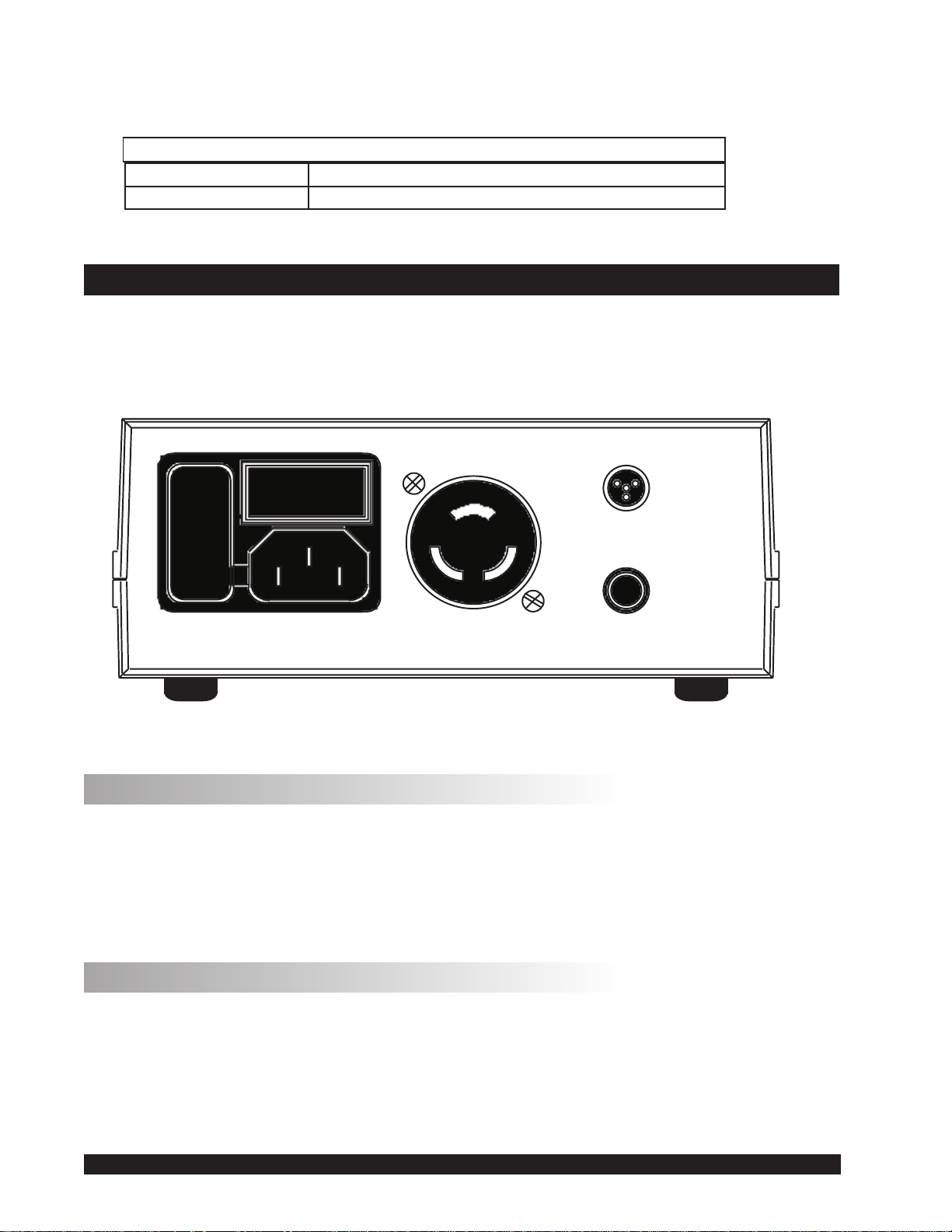
III. INSTALLATION
Plug the R TD Temperature Probe (DVP-94Y) into the “probe” receptacle, the Thermo Container
into the “Thermosel” receptacle, and a strip chart recorder (if used) into the recorder jack. The
rear panel will appear as follows in Figure 1.
OFF ON
Thermosel
Probe
F
U
S
E
Power Input
Figure 1
III.1 Probe
Recorder
The probe is a 100 ohm precision platinum RTD (Resistance Temperature Detector) probe
(Brookfield Part No. DVP-94Y) which is plugged into the probe port on the rear panel.
Note: The RTD Probe must be plugged into the Model 75 Controller and the RTD Probe end
must be inserted into the Thermo Container before power is turned on. An error message
will be displayed if the Model 75 Controller is turned on and the RTD Probe is not installed.
III.2 Recorder
The recorder jack provides a signal to a recording device (the HT-88Y cable is provided for this
service) such as a strip chart recorder . The full scale recorder output signal range is from 0 to 4 V
for the Thermosel. The temperature can be obtained from the output potential (in mV) as follows:
Brookfield Engineering Labs., Inc. Page 4 Manuel No. M/94-203-D89
The 0 to 4 volt output corresponds to a temperature range of -100°C (-148°F) to 300°C (572°F).
Realistically, temperatures in the Thermosel will typically be above ambient. Therefore, output
voltages will generally range from slightly less than 2 volts (<100°C) to the full 4 volts (300°C).
Brookfield Engineering Labs., Inc. Page 4 Manual No. M/98-205-A0100
Page 5

The temperature corresponding to any intermediate output voltage can be obtained from the following:
(0.1 x mV) - 100 = °C (Centigrade T emperatures)
(0.18 x mV) - 48 = °F (Fahrenheit Temperatures)
For example, the temperature corresponding to a reading of 2.5 V (2500 mV) would be calculated as follows:
(0.1 x 2500) - 100 = 150°C or (0.18 x 2500) - 148 = 302°F
The recorder jack is a standard 1/4" phono jack. An analog output cable (Brookfield Part No.
HT-88Y) is provided with the Model 75 Controller. Single channel and dual channel strip chart
recorders are available from Brookfield.
III.3 AC, Power Switch and Power Fuse
The power requirement for the Model 75 Controller is 85-265 VAC, 50/60 Hz. and must be
connected through the power cord. The voltage for which the unit has been configured will be
indicated on the bottom of the Model 75 Controller. The power consumption at 120 VAC is 400
mA plus the Thermo Container load power.
The power fuses must be 3A/ 250V fast blow Littlefuse type 3AG 312.003 or equivalent. These
fuses protect the controller electronics only on the hot and neutral lines.
III.4 Load
The “Thermosel” connector is provided to supply power to the Thermo Container . The connector
is specially keyed so that other loads cannot be readily substituted. The power limit supplied by
this connector is 300 watts.
Note: The current provided to the Thermosel connector is potentially dangerous. Do not insert
or remove the load plug while power is applied to the Model 75 T emperature Controller .
Brookfield Engineering Labs., Inc. Page 5 Manual No. M/98-205-A0100
Page 6

IV. CONTROL KEYS AND DISPLAY PANEL
The front panel of the unit which includes all user controls and status indicators is shown in
Figure 2:
Temperture Controller
°F
°C
RUN
HEAT
SET
Figure 2
RUN
STBY
The digital display is used to set temperature values, to show system status during operation and
to present certain messages to the user.
The allowable range for temperature entries is from 0°C to 300.0°C (32.0°F to 572.0°F), with a
minimum increment of 0.1° (either scale). If a proposed temperature value is above the maximum or below the minimum input, an audible sound (beep) will be heard and the current maximum (or minimum) value will be displayed.
The various buttons and light emitting diodes (LED’s) have the following functions or meanings:
IV.1
°F
The °F/°C Key
°C
This key is used to toggle the units in which temperature is displayed and entered. The rightmost
digit in the main display indicates the units currently being used (F = Fahrenheit; C = Centigrade).
IV.2
The
setpoint operation, press
of the controller. When the Temperature Controller is operating, pressing the
RUN
The RUN/STBY Key
key initiates or stops operation of the Model 75 Controller. To initiate a temperature
RUN
. The LED labeled “RUN” will light up to indicate the present status
STBY
RUN
key will place
STBY
RUN
STBY
STBY
the unit in a standby mode and cease control of the Thermo Container.
Brookfield Engineering Labs., Inc. Page 6 Manual No. M/98-205-A0100
Page 7

IV.3
SET
The SET Key
The SET key is pressed when the operator wants to view or edit temperature data.
IV.4 The Arrow (direction) Ke ys
The ARROW keys are used to increment (or decrement) temperature values. To input temperatures, a single press of either of these keys will result in a single digit increment in the displayed
temperature value. When large temperature steps are required, the user will find it simpler to
press and hold these keys and scroll through available numbers. At first, this will result in a slow
increment (or decrement) of the display temperature. However, after a couple of seconds, the
display will rapidly increment (or decrement) and the user must be careful not to overshoot (or
undershoot) the desired input value.
IV.5 HEA T
The HEAT LED
The HEAT LED is illuminated when the controller is providing power to the Thermo Container.
The LED will flash at a rapid rate when the temperature of the Thermo Container is being maintained at a set temperature.
IV.6 RUN
The RUN LED
The RUN LED is illuminated when the temperature of the Thermo Container is being controlled
by the Model 75 Controller.
Piezo Buzzer
IV.7
The unit includes a buzzer which will provide an audible tone (beep) in the following situations:
• During the Model 75 Controller’s startup sequence.
• If an unacceptable data entry has been made (e.g. attempting to set a temperature above or
below the allowable inputs).
• If the temperature probe is not plugged in or becomes disconnected.
V. TEMPERATURE CONTROLLER OPERATION
V.1 Powering Up the Model 75 Temperature Controller
The Model 75 Controller is turned on by placing the rear panel mounted ON/OFF switch in the
ON position. The buzzer will “beep” and, after a few seconds, the digital display will indicate the
present temperature of the Thermo container. When the unit is initialized, all of the indicator
LED’s are off.
Brookfield Engineering Labs., Inc. Page 7 Manual No. M/98-205-A0100
Page 8

V.2 Setting a Temperature
1) Press the
Note: The Model 75 Controller will display the last set point temperature value upon
SET
key.
entering the temperature setpoint screen.
If you do not press either of the
or
keys or the
SET
key within approximately 4-5
seconds, the Model 75Controller will “beep” and revert to its non setpoint mode (the
SET
temperature will again be displaying tenth degree values). Simply press the
key again
to re-enter the temperature setpoint mode.
2) A press of either the
or
keys will cause the tenths degree digit to stop flashing and
the tenths degree value to begin incrementing (or decrementing) at a one-to-two character
per second rate. When the scrolled tenths value exceeds ten-tenths of a degree (i.e. one
degree) in either direction, the scroll speed will then accelerate and the ones digit will then
be incremented (or decremented) as required. If the or keys are held in for an
extended time, the scroll speed will again increase to its maximum rate.
3) If the user lets up on an
or
key for more than the 4-5 second timeout period, the
display will revert to that of the current Thermo Container temperature with no change in
SET
the setpoint temperature taking place. At this point, a press of the
key will display the
last valid setpoint temperature that existed before the user began to change the setpoint
temperature.
4) If the user lets up on the
then re-presses an
or
or
key for less than the 4-5 second timeout period, and
key, the display will return to the tenths degree digit set mode
and again the temperature set mode as described above.
5) If the user scrolls to some new setpoint temperature, lets up on the
presses the
new set point temperature. If the user had pressed the
SET
key, the Model 75 Controller will accept the scrolled to temperature as the
RUN
STBY
instead of the
or
SET
keys and
key, the
Model 75 Controller would have begun controlling the Thermo Container at the new
scrolled-to setpoint temperature. In this case, the RUN LED would illuminate and the
HEAT
LED may or may not be lit depending on the temperature in the Thermo Container compared to the setpoint temperature. In any case, the Model 75 Controller action
will regulate the temperature of the Thermo Container to the new setpoint temperature. The
current temperature of the Thermosel Container will be displayed on the front panel digital
display with the RUN LED illuminated. Power will be provided to the Thermo Container if the new setpoint temperature is above the previous temperature of the Thermo
Container. When power is provided to the Thermo Container, the HEAT
LED will be
illuminated. The Model 75 Controller will provide power to reach the indicated set point
and maintain it at that level indefinitely.
Brookfield Engineering Labs., Inc. Page 8 Manual No. M/98-205-A0100
Page 9

Note: The last scrolled-to-temperature (the last setpoint temperature) will be retained in
non-volatile memory and will become the default setpoint temperature the next time
the temperature controller is powered up.
6) Temperature control of the Thermo Container will be maintained for as long as the Model
75 Controller is powered up, or until the
VI. ERR OR MESSAGES AND FAIL SAFES
If the display shows an error message or there is a continuous “beeping”, you are in one of
the following error conditions:
1) The RTD probe has become disconnected from the Model 75 Controller. Plug the RTD probe
in to correct the error.
2) The Model 75 Controller is providing power to the Thermo Container, but the temperature
sensor is not reporting an increase in temperature. The power to the Thermo Container will be
interrupted. It will be necessary to power down the Model 75 Controller and determine the
cause of the fault before continuing operation.
3) The Model 75 Controller sensed a temperature higher or lower than its built-in limits. The
following paragraphs provide further detail.
VI.1 Open Sensor Error
If the sensor fails or an open circuit condition occurs (infinite resistance), the unit will cause a
probe error as follows:
RUN
STBY
key is pressed to stop the control action.
0ˉ
Note that this error message could be momentarily preceded by either of the following displays:
lÏ--
h1-
The Model 75 Controller will stop control and will stay in this state until the problem is corrected.
This is usually due to the R TD temperature probe not being plugged into the Model 75 Controller .
Once corrected, the unit will return to viewing the “controlled” temperature.
Brookfield Engineering Labs., Inc. Page 9 Manual No. M/98-205-A0100
-
Page 10

VI.2 Thermosel Overheat Error
If the sensor becomes dislodged or is left out of the Thermo Container or if the Thermo Container
coils become “open”, and the Model 75 Controller is not sensing a temperature rise while dispensing power to the Thermo Container, it will display the following message after approximately a 3-minute delay:
eÂÂ
The Model 75 Controller will stop control and will stay in this state until the problem is corrected.
The only way to correct this error is to turn off the Model 75 Controller and then turn it back on.
VI.3 High/Low Temperature Limit Error
If a temperature outside of the Temperature Controllers high or low temperature limits is detected, either of the two messages stop control and will stay in this state until the problem is corrected. Once corrected, the unit will
return to viewing the controlled temperature.
LoLo
Lo- or -
LoLo
HIHI
HI- will be displayed. The Model 75 Controller will
HIHI
VII. TROUBLESHOOTING
In the event that the Model 75 Controller does not appear to be working, disconnect the unit from
the power source (mains) and check the power fuses (located in a removable section of the power
input block) to determine whether they are still functional. Refer to Figure 1, Section III - use
screwdriver to remove fuse holder.
The power fuses protect the controller electronics. These fuses (Brookfield Part No. HT-98H) are
3A/ 250V fast blow Littlefuse type 3AG 312.003 or equivalent.
The Model 75 Controller is designed to require a minimum amount of user maintenance. There
are no user serviceable parts inside the unit. In the event of difficulties with the product, con-
tact Brookfield Engineering Laboratories or its authorized representative. Please have the serial
number of the unit available (the serial number is indicated on a label on the bottom of the
controller).
Brookfield Engineering Labs., Inc. Page 10 Manual No. M/98-205-A0100
Page 11

Appendix A - Warranty Repair and Service
Warranty
The Brookfield Model 75 Temperature Controller is guaranteed for one year from date of purchase
against defects in materials and workmanship. The Controller must be returned toBrookfield Engineering Laboratories, Inc. or the Brookfield dealer from whom it was purchased for no charge warranty
service. Transportation is at the purchaser’s expense.
For repair or service in the United States return to:
Brookfield Engineering Laboratories, Inc.
11 Commerce Boulevard
Middleboro, MA 02346 U.S.A.
Telephone: (508) 946-6200 FAX: (508) 946-6262
For repair or service outside the United States, consult Brookfield Engineering Laboratories, Inc. or
the dealer from whom you purchased the instrument.
For repair or service in the United Kingdom, return to:
Brookfield V iscometers Limited
1 Whitehall Estate
Flex Meadow
Pinnacles West
Harlow, Essex CM19 5TJ, United Kingdom
Telephone: (44) 27/945 1774 FAX: (44) 27/945 1775
For repair or service in Germany, return to:
Brookfield Engineering Labs. Vertriebs GmbH
Barbarossastrasse 3
D-73547 Lorch, Germany
Telephone: 7172/927100 FAX: 7172/927105
Brookfield Engineering Labs., Inc. Page 12 Manuel No. M/94-203-D898
Brookfield Engineering Labs., Inc. Page 11 Manual No. M/98-205-A0100
 Loading...