

Page 1

SPECIALISTS IN THE
MEAS UREMENT AND
CONTROL OF VISCOSITY
TEL 508-946-6200
FAX 508-946-6262
or 800-628-8139 (USA excluding MA)
I
NTERNET
http://www.brookfieldengineering.com
BROOKFIELD ENGINEERING LABORA TORIES, INC.
11 Commerce Boulevard, Middleboro, MA 02346 USA
with offices in
:
Boston • Chicago • London • Stuttgart • Guangzhou
BROOKFIELD MODEL 106
Programmable Temperature Controller
Operating Instructions
Manual No. M/02-207-C0109
Brookeld Engineering Labs., Inc. Page 1 Manual No. M/02-207-C0109
Page 2

TABLE OF CONTENTS
I. INTRODUCTION ............................................................................................................................3
II. SPECIFICATIONS .........................................................................................................................4
III. SAFETY SYMBOLS AND PRECAUTIONS ...................................................................................... 5
IV. INSTALLATION .............................................................................................................................. 6
IV.1 Probe ...........................................................................................................................6
IV.2 Recorder .....................................................................................................................
IV.3 Comm Port .................................................................................................................
IV. 4 AC, Power Switch and Power Fuse ...........................................................................
IV. 5 Load ............................................................................................................................
V. CONTROL KEYS AND DISPLAY PANEL ....................................................................................... 9
V.1 The °F/°C Key ............................................................................................................9
V.2 The Run/Stby Key ....................................................................................................
V.3 The Set Key ..............................................................................................................
V.4 The Program Key .....................................................................................................
V.5 The Arrow (direction) Keys .....................................................................................
V.6 The Heat On LED ....................................................................................................
V.7 The Remote LED .....................................................................................................
V.8 The Run LED ...........................................................................................................
V.9 The Program LED ....................................................................................................
V.10 Piezo Buzzer .............................................................................................................
10
10
10
10
10
11
11
11
11
6
7
7
8
VI. PROGRAMMABLE TEMPERATURE CONTROLLER OPERATION ................................................12
VI.1 Powering Up the Temperature Controller ................................................................12
VI.2 Control Modes ..........................................................................................................
VI.3 Single SetPoint Operation - Non Program Mode .....................................................
VI.4 Program Mode ..........................................................................................................
VI.5 Entering a Temperature/Time Program ....................................................................
VI.6 Reviewing and Editing An Existing Program ..........................................................
VI.7 Running a Temperature/Time Program ....................................................................
VI.8 Stopping A Program .................................................................................................
VI.9 Remote Operation ....................................................................................................
VII. REMOTE OPERATION USING RHEOCALC© ............................................................................... 21
VIII. ERROR MESSAGES AND FAILSAFES ........................................................................................21
12
12
14
14
17
17
18
18
VIII.1 Open Sensor Error ....................................................................................................22
VIII.2 Thermosel Overheat Error ........................................................................................
VIII.3 High/Low Temperature Limit Error .........................................................................
IX. TROUBLESHOOTING ................................................................................................................ 23
APPENDIX A - External Mode Command Protocol Demonstration .................................................................24
APPENDIX B - Warranty Repair and Service .............................................................................................................27
22
23
Brookeld Engineering Labs., Inc. Page 2 Manual No. M/02-207-C0109
Page 3
I. INTRODUCTION
The Programmable Temperature Controller is used with the Brookeld Thermosel for measuring
viscosity at high temperatures. The unit includes a solid state proportioning temperature control-
ler, a means for entering the desired temperature/time data and appropriate status indicators.
The Programmable Temperature Controller can maintain a constant temperature in the Thermosel
or be programmed to effect temperature changes. The program indicates each desired temperature and the period of time that the Thermosel should be maintained at that temperature. In this
manual, a time/temperature combination is termed an “entry” or “step”. A program can have up
to 10 entries. The Programmable Temperature Controller can automatically stop maintaining the
temperature of the Thermosel Container at the termination of the program. Alternatively, the Programmable Temperature Controller can be programmed to maintain the nal preset temperature
at the termination of the program.
The front panel is used to display and edit temperature/time programs. The front panel also presents the status of the system (e.g. the current temperature of the Thermosel and error messages).
An RS-232C communication channel is provided to establish control and/or observe operating
parameters via a remote device (e.g. a personal computer or a remote terminal). Rheocalc, an
optional software package available from BROOKFIELD, can be used, in conjunction with the
Brookeld DV-II+ Pro Viscometer, DV-III+ Rheometer or DV-III Ultra Rheometer, to provide
temperature/time inputs to the Programmable Temperature Controller via a personal computer.
(Optional Cable HT-106 is required to interface the Programmable Temperature Controller to the
PC.)
An analog output port is available to send temperature data to a strip chart recorder. Optional
Recorder Output Cable (Part No. HT-88Y) is available from Brookeld.
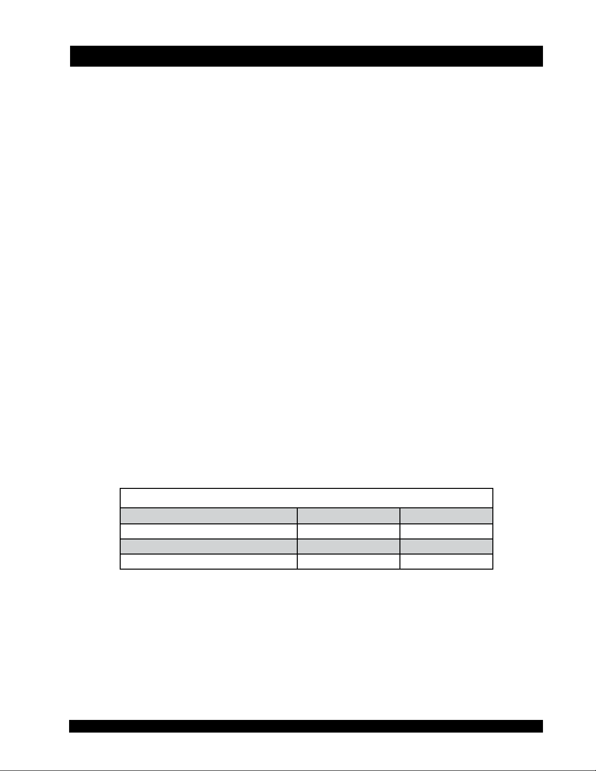
A list of the parts shipped with the Programmable Temperature Controller is provided below. If
any parts are missing or damaged, please contact BROOKFIELD or your local authorized representative immediately.
SYSTEM CONTENTS
Description
Programmable Temperature Controller
RTD Temperature Probe
Operating Instructions Manual M/02-207 1
Part Number
HT-110 1
DVP-94Y 1
Quantity
Table I.1
If you intend to use this Programmable Temperature Controller with a Brookeld DV-II+ Pro
Viscometer, DV-III+ or DV-III Ultra Rheometer, optional cables are required:
• For direct temperature control (via DV-III+/DV-III Ultra), you will require optional cable
DVP-141
• For temperature control using Rheocalc software (via computer), you will require option
al cable HT-106
-
Please contact Brookeld or your local authorized representative with your Thermosel Controller
Serial Number to obtain these cables.
Brookeld Engineering Labs., Inc. Page 3 Manual No. M/02-207-C0109
Page 4

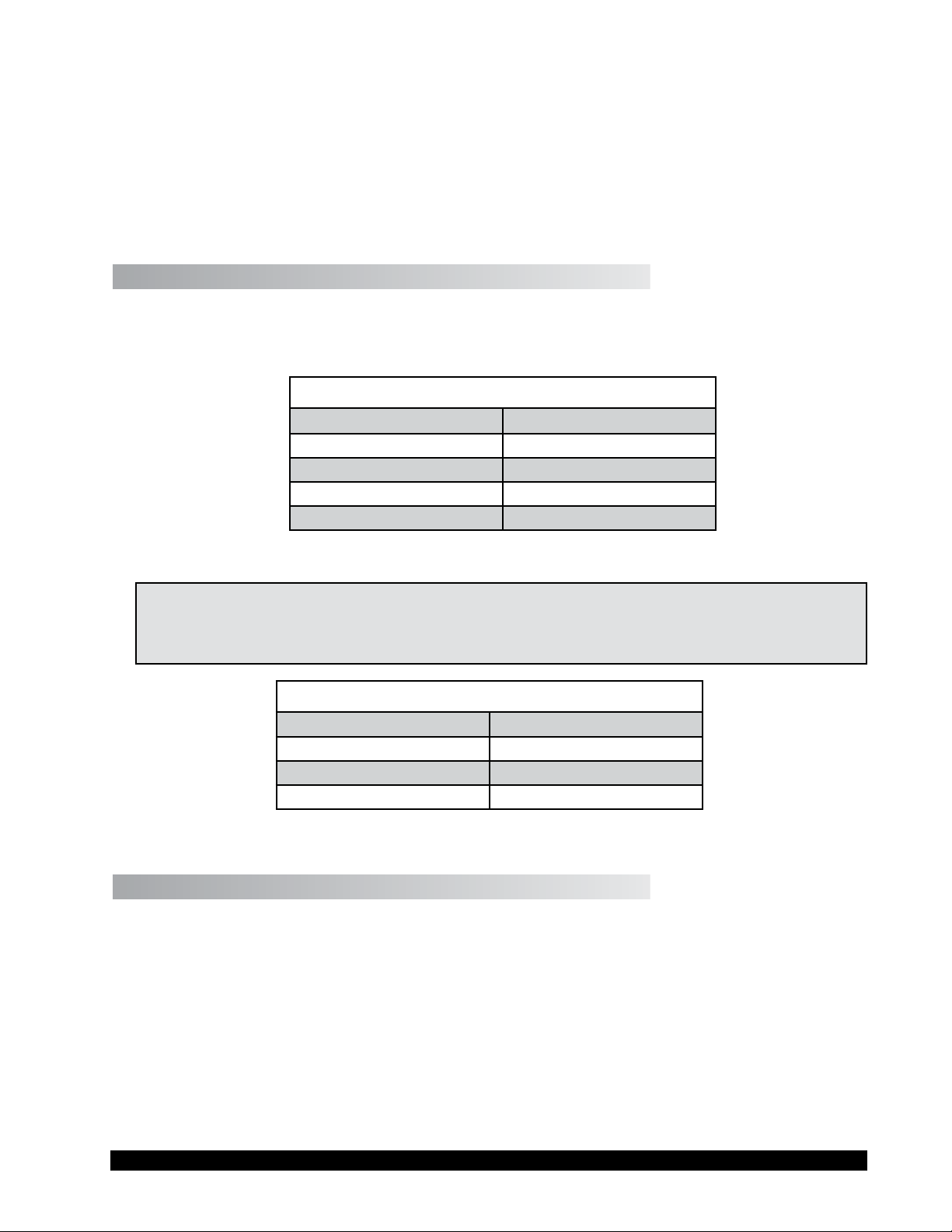
II. SPECIFICATIONS
Utilities
VOLTAGE SPECIFICATIONS
Controller
Input Voltage
Input Frequency 50/60 Hz
Replaceable Fuses Two fuses, 2A, 250V, 5 x 20 mm, Fast Acting
Load TRIAC (250 watts max)
85 to 265 VAC
(Check the label beneath the Programmable
Temperature Controller for the voltage require
ments of our unit)
-
Table II.1
MEASUREMENT/CONTROL SPECIFICATIONS
Range 15°C above ambient to 300°C
27°F above ambient to 572°F
Resolution 0.1 °C or °F
Reading Accuracy
Setpoint Accuracy The temperature will be maintained within 0.3°C
Recorder Output Voltage 0 to 4 Volts
±1.0°C (between ambient and +150°C)
±2.0°C (between +151°C and +300°C)
of the setpoint
1 volt = 0°C/32°F; 4 Volts = 300°C/572°F
Table II.2
NOTE: The temperature accuracies stated above are a result of the combined accuracies of
the Programmable Temperature Controller, the temperature probe, and the Thermo
container.
Thermo Container
THERMO CONTAINER SPECIFICATIONS
Range
Accuracy ±0.5% of the controller setpoint
15°C above ambient to 300°C
Table II.3
Brookeld Engineering Labs., Inc. Page 4 Manual No. M/02-207-C0109
Page 5

Electrical Certications
Conforms to CE Standards:
BSEN 50081-1: Emission Standard - Light Industrial
BSEN 50082-1: Immunity Standard - Light Industrial
BSEN 61010-1: Safety requirements for electrical equipment, for measurement, control and
laboratory use.
III. SAFETY SYMBOLS AND PRECAUTIONS
Safety Symbols
The following explains safety symbols which may be found in this operating manual.
Refer to the manual for specic warning or caution information to avoid personal injury
or damage to the instrument.
Precautions
This instrument is not intended for use in a potentially hazardous environment.
If this instrument is not used in a manner specied by the manufacturer, the protection
provided by the instrument may be insufcient.
Brookeld Engineering Labs., Inc. Page 5 Manual No. M/02-207-C0109
Page 6
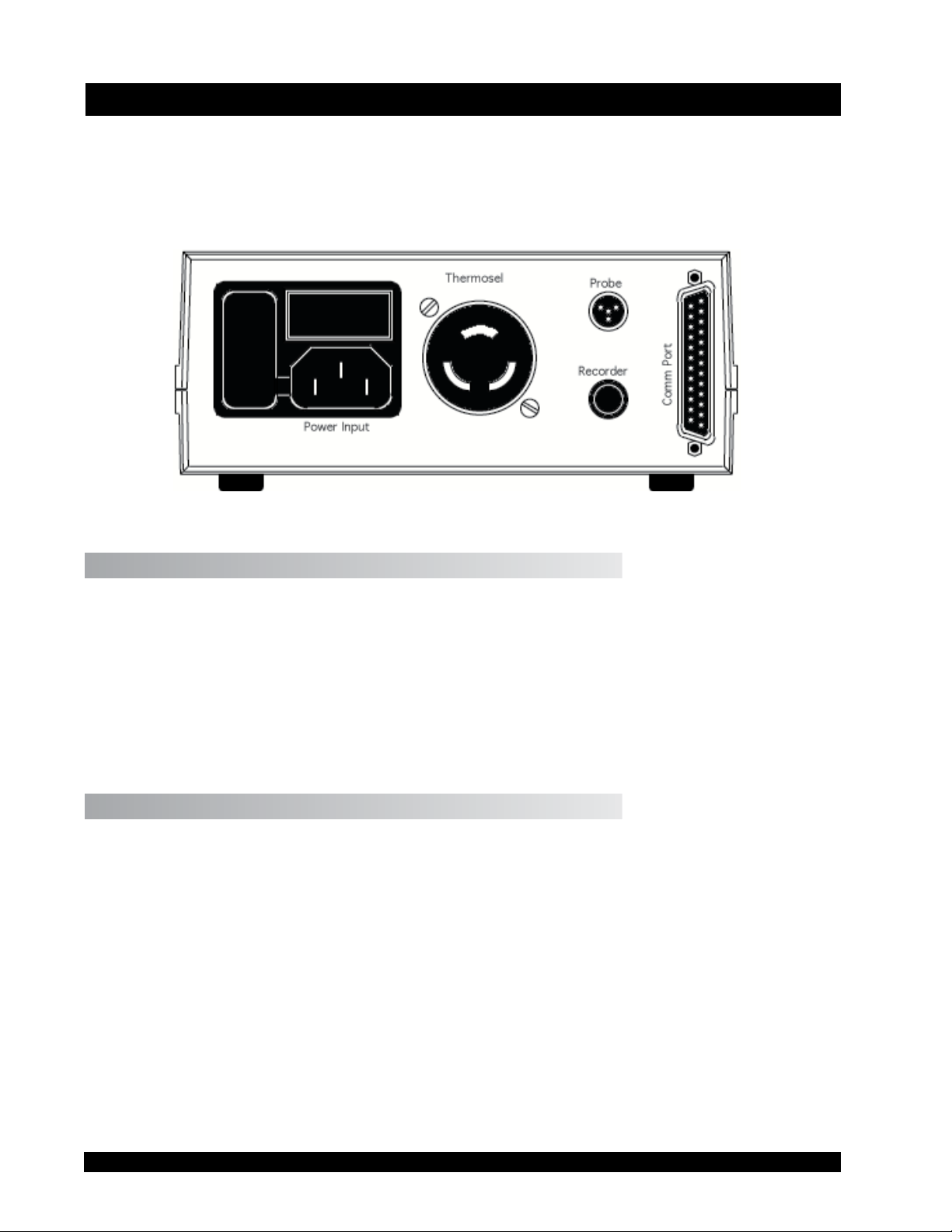
IV. INSTALLATION
Plug the temperature sensor into the Probe receptacle, the Thermo Container into the Thermosel
receptacle, the strip chart recorder (if used) into the Recorder jack and a remote RS-232C device
(again, if used) into the Comm Ports 25-pin plug. The rear panel will appear as follows in
Figure IV.1.
Figure IV.1
IV.1 Probe
The probe is a 100 ohm precision platinum RTD (resistance temperature detector) probe (Brook-
eld Part Number DVP-94Y) which is plugged into the Probe port on the rear panel.
Note: The RTD Probe must be plugged into the Programmable Temperature Controller and
the RTD Probe end must be inserted into the Thermo Container before power is turned
on. The Controller will beep on/off. An error message (0.RTD) will be displayed if
the Programmable Temperature Controller is turned on and the RTD Probe is not installed.
IV.2 Recorder
The Recorder jack provides a signal to a recording device (the optional HT-88Y cable is provided
for this service) such as a strip chart recorder. The full scale recorder output signal range is from
0 to 4 V for the Thermosel systems. The temperature can be obtained from the output potential
(in mV) as follows:
The 0 to 4 volt output corresponds to a temperature range of -100°C (-148°F) to 300°C (572°F).
Realistically, temperatures in Thermosel systems will typically be above ambient. Therefore,
output voltages will generally range from slightly less than 2 volts (<100°C) to the full 4 volts
(300°C). The temperature corresponding to any intermediate output voltage can be obtained from
the following:
(0.1 * mV) -100 = °C (Centigrade Temperatures)
(0.18 * mV) -148 = °F (Fahrenheit Temperatures)
Brookeld Engineering Labs., Inc. Page 6 Manual No. M/02-207-C0109
Page 7
For example, the temperature corresponding to a reading of 2.5 V (2500 mV) would be calculated as follows:
(0.1 x 2500) - 100 = 150°C or (0.18 x 2500) - 148 = 302°F
The recorder jack is a standard 1/4” phono jack. An optional analog output cable (Brookeld
Part No. HT-88Y) is available from Brookeld.
IV.3 Comm Port
The COMMUNICATION PORT provides an RS-232C data link to an external device such as a
computer or remote terminal. The RS-232C pin assignments are:
RS-232C PIN CONNECTIONS
Pin Number
2 Data Out (Tx)
3 Data In (Rx)
7 Ground (Gnd)
13 and 25 Remote Mode
Function
Table IV.1
NOTE: Pin number 13 should be connected to pin 25 on the connector being inserted into the
Comm Port in order to place the Programmable Temperature Controller in the Remote
mode (indicated by the lit REMOTE LED on the instrument front panel).
RS-232C Protocol
Baud Rage
Data Bits
Stop Bits
Parity
9600
8
1
None
Table IV.2
IV.4 AC, Power Switch and Power Fuse
The primary power requirement for the Programmable Temperature Controller can range from 85
to 265 VAC; 50/60 Hz and must be connected through the power cord. The voltage for which the
unit has been congured will be indicated on the bottom of the Programmable Temperature Con-
troller. The power consumption at 120 VAC is 400 ma plus the Thermo Container load power.
The power fuse must be a 2A/250V Littlefuse, fast acting type, GMA series or equivalent. This
fuse protects the controller electronics only.
Brookeld Engineering Labs., Inc. Page 7 Manual No. M/02-207-C0109
Page 8

IV.5 Load
The Thermosel connector is provided to supply power to the Thermo Container. The connector
is specially keyed so that other loads cannot be readily substituted. The power limit supplied by
this connector is 300 watts.
NOTE: The current provided to the Thermosel connector is potentially dangerous. Do not insert
or remove the Load plug while power is applied to the Programmable Temperature Controller.
Brookeld Engineering Labs., Inc. Page 8 Manual No. M/02-207-C0109
Page 9
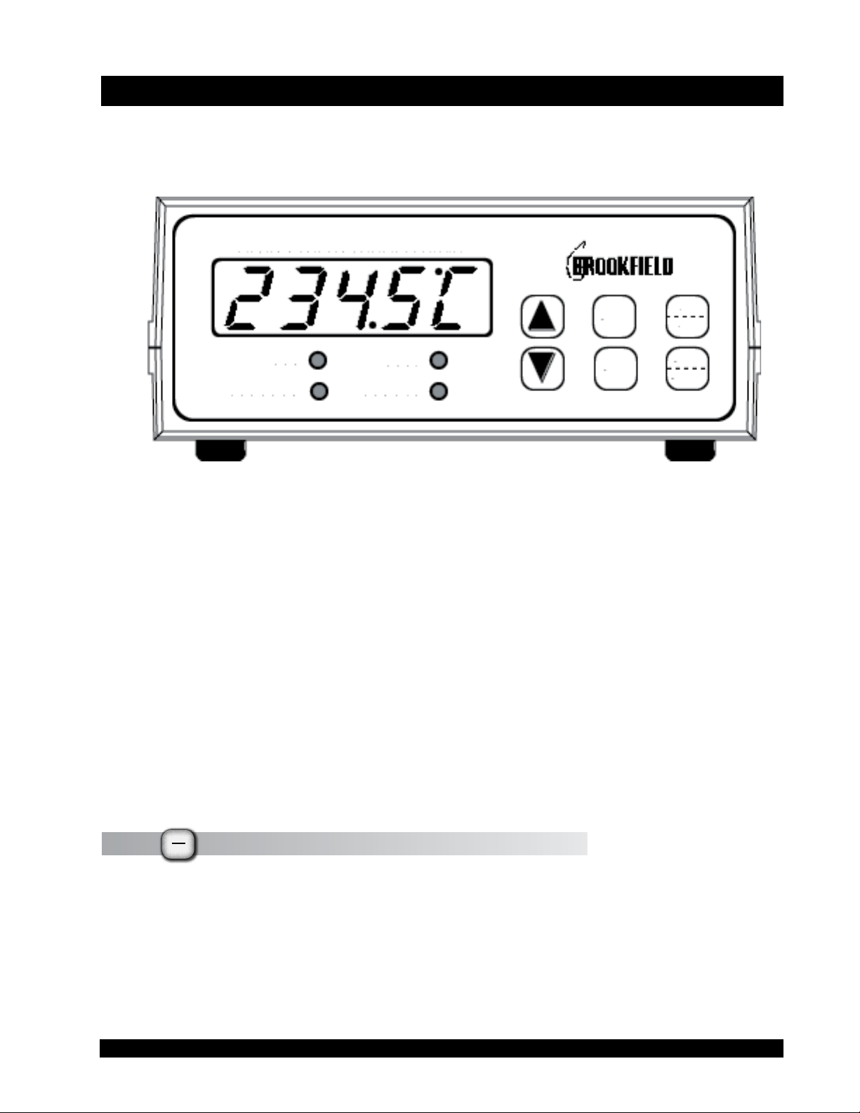
V. CONTROL KEYS AND DISPLAY PANEL
The front panel of the unit, which includes all user controls and status indicators, is shown in
Figure V.1:
Figure V.1
The digital display is used to display system status, to set up temperature/time programs, to review temperature/time programs and to present certain messages to the user.
The allowable range for temperature entries is:
0.0°C to 300.0°C (32.0°F to 572.0°F), with a minimum increment of 0.1° (either scale). The allowable range for time entries is from 1 to 900 minutes with a minimum increment of 1 minute.
If a proposed temperature value is above the maximum input for that unit, or if a proposed temperature value is below the minimum input for that unit, an audible sound (beep) will be heard
and the current maximum (or minimum) value will be displayed.
The various buttons and light emitting diodes (LED’s) have the following functions or meaning:
V.1
°F
The °F/°C Key
°C
This key is used to toggle the units in which temperatures are displayed and entered. The right
most digit in the main display indicates the units currently being used (F = Fahrenheit; C = Centigrade).
Brookeld Engineering Labs., Inc. Page 9 Manual No. M/02-207-C0109
Page 10

V.2
RUN
The Run/Stby Key
STBY
The RUN/STBY key initiates or stops operation of the Programmable Temperature Controller. To
initiate a temperature program or single setpoint operation, press RUN/STBY. The LED labeled
RUN will light up to indicate the present status of the controller. When the Temperature Controller is operating, pressing the RUN/STBY key will place the unit in a standby mode and cease
control of the Thermo Container.
V.3
SET
The Set Key
The SET key is pressed when the operator wants to view or edit temperature and time data. In
single setpoint (non-program) mode, the SET key accesses the temperature setpoint. In programmed mode, the SET key is used to cycle through the time/temperature program and to accept various options when the user is “building” a temperature/time program.
PGM
V.4
The Program Key
The PGM key is pressed when the operator wants to establish, review or use a temperature/time pro-
gram. The LED labeled PROGRAM is illuminated when the Programmable Temperature Controller
is in the program mode.
p
V.5
q
The Arrow (direction) Keys
The ARROW keys are used to increment (or decrement) temperature values and to scroll through
sub-program options where required. When used to input temperatures, a single press of either
of these keys will result in a single digit increment in the displayed temperature value. When
large temperature steps are required, the user will nd it simpler to press and hold these keys. At
rst, this will result in a slow increment (or decrement) of the display temperature. However,
after a couple of seconds, the display will rapidly increment (or decrement) and the user must be
careful not to overshoot (or undershoot) the desired input value.
These keys will not work when the Programmable Temperature Controller is in the run mode.
V.6 HEAT The Heat LED
The HEAT LED is illuminated when the controller is providing power to the Thermo Container.
The LED will ash at a rapid rate when the temperature of the Thermo Container is being maintained at a programmed temperature.
Brookeld Engineering Labs., Inc. Page 10 Manual No. M/02-207-C0109
Page 11

V.7 REMOTE The Remote LED
The REMOTE LED is illuminated when an RS-232C cable (Brookeld Part No. HT-106 for connecting the Model 106 to a computer) is plugged into the Programmable Temperature Controller.
V.8 RUN
The Run LED
The RUN LED is illuminated when the temperature of the Thermo Container is being controlled
by the Programmable Temperature Controller.
V.9 PROGRAM The Program LED
The PROGRAM LED is illuminated when a temperature program is being established, viewed or
run.
V.10 Piezo Buzzer
The unit includes a buzzer which will provide an audible tone (beep) in the following situations:
• During the Programmable Temperature Controller startup sequence.
• When a temperature/time program has been completed.
• If an illegal data entry has been made (e.g. attempting to set a temperature above or be-
low the allowable inputs).
• If the temperature probe is removed.
Brookeld Engineering Labs., Inc. Page 11 Manual No. M/02-207-C0109
Page 12

VI. PROGRAMMABLE TEMPERATURE CONTROLLER OPERATION
VI.1 Powering Up the Temperature Controller
The Programmable Temperature Controller is turned on by placing the rear panel mounted ON/
OFF switch in the ON position. The buzzer will beep and, after a few seconds, the digital display
will indicate the present temperature of the Thermo container. When the unit is initialized, all of
the indicator LED’s are off. The REMOTE LED will be illuminated if the Programmable Tem-
perature Controller is connected to an external device through the HT-106 cable.
VI.2 Control Modes
The user can select one of three control modes.
In the MANUAL or SINGLE SETPOINT MODE, the Programmable Temperature Controller
functions as a single setpoint controller. The user sets a desired temperature, presses the RUN/
STBY key and the unit will control the Thermo Container at this temperature indenitely until
the unit is shut off, or a new setpoint is entered and run or the Programmable Temperature Con-
troller is placed in the standby mode.
In the PROGRAM MODE, the Programmable Temperature Controller functions as a multiple
setpoint temperature controller. The user may dene up to ten different setpoints in the controller’s memory. The user must also dene the time interval which will be used for each temperature
setpoint (up to 15 hours 00 minutes per setpoint). The user may then run this pre-set program and
the Programmable Temperature Controller will automatically execute the program. The Thermo
Container will be controlled to a specied setpoint temperature for the specied time interval
and then the setpoint will be automatically changed to the next programmed temperature. The
programmed setpoints may be of a “RAMP UP” type, “RAMP DOWN” type or a mixture of the
two. At the last step of the program, the user can have the Programmable Temperature Controller stop controlling temperature after the last setpoint has been held at the last prescribed time
interval, or continue controlling at the last setpoint temperature indenitely.
In the REMOTE MODE the Programmable Temperature Controller accepts and executes com-
mands from an external control device via the HT-106 cable. You may not use the REMOTE
MODE to run the program resident in the Programmable Temperature Controller memory.
The sections that follow explain these options in greater detail. The Programmable Temperature
Controller may only be used in one of these modes at a time.
VI.3 Single SetPoint Operation - Non Program Mode
In the single setpoint mode of operation, the system is operated at a constant temperature. To
establish the desired temperature, use the following procedure:
SET
1) Press the
Brookeld Engineering Labs., Inc. Page 12 Manual No. M/02-207-C0109
key.
Page 13

NOTE: The Temperature Controller will display the last set point temperature value upon
entering the temperature setpoint screen.
If you do not press either of the
onds, the Temperature Controller will “beep” and revert to its non setpoint mode (the temperature
will again be displaying tenth degree values). Simply press the
temperature setpoint mode.
2) A press of either the
and the tenths degree value to begin incrementing (or decrementing) at a one-to-two char-
acter per second rate. When the scrolled tenths value exceeds ten-tenths of a degree (i.e.
one degree) in either direction, the scroll speed will then accelerate, and the ones digit
will then be incremented (or decremented) as required. If the
in for an extended time, the scroll speed will again increase to its maximum rate.
3) If the user releases the
the display will revert to that of the current Thermo Container temperature with no
change in the setpoint temperature taking place. At this point, a press of the
display the last valid setpoint temperature that existed before the user began to change
the setpoint temperature.
4) If the user releases the
p
p
p
p
or
or
q
or
or
keys or the
q
keys will cause the tenths degree digit to stop ashing
key after more than the 4-5 second timeout period,
q
q
key after less than the 4-5 second timeout period, and
SET
key within approximately 4-5 sec-
SET
key again to re-enter the
p
or
keys are held
q
SET
key will
then re-presses an
mode and again begin the temperature set mode as described above.
5) If the user scrolls to some new setpoint temperature, releases the
presses the
as the new setpoint temperature. If the user had pressed the
the temperature controller would have begun controlling the Thermo Container at the new
scrolled-to setpoint temperature. In this case, the RUN LED would illuminate and
the HEAT LED may or may not be lit depending on the temperature in the Thermo
Container.
In any case, the Temperature Controller action will be to regulate to the new setpoint tempera-
ture. The current temperature of the Thermo Container will be displayed on the front panel
digital display with the RUN LED illuminated. Power will be provided to the Thermo Container if the new setpoint temperature is higher; the Thermo Container HEAT LED will be
illuminated. The Temperature Controller will provide power to reach the indicated set point and
maintain it at that level indenitely.
NOTE: The last scrolled-to-temperature (the last setpoint temperature) will be re-
SET
key, the Temperature Controller will accept the scrolled-to temperature
tained in non-volatile memory and will become the default setpoint tempera-
ture the next time the Temperature Controller is powered up.
p
or
key, the display will return to the tenths degree digit set
q
p
RUN
instead of the
STBY
or
keys and
q
SET
key,
Brookeld Engineering Labs., Inc. Page 13 Manual No. M/02-207-C0109
Page 14

6) Temperature control of the Thermo Container will be maintained for as long as the Temper-
ature Controller is powered up, or until the
RUN
key is pressed to stop the control action.
STBY
VI.4 Program Mode
There are two options available to the user in the PROGRAM MODE:
1) Run a program and terminate temperature control at the end of the program cycle.
2) Run a program and maintain temperature control at the last program setpoint temperature.
The fundamental approach to programmed operation is to create a table that includes the desired
temperatures and the hold time period that is required for each temperature. A sample tempera-
ture/time program is shown in Table 7. Entry number 6 in the table is the last desired temperature
step. Please note that the remaining program slots 7, 8 and 9 may have temperatures in them.
SAMPLE TEMPERATURE/TIME PROGRAM
TEMPERATURE
(°C)
100.0 5
140.0 15 1
160.0 10 2
205.0 8 3
240.0 4 4
265.0 5 5
290.0 2 6
HOLD TIME
(Minutes)
ENTRY
NUMBER
0
Table VI.1
The time required to reach a temperature set point is dependent on a variety of factors such as
the ambient temperature and the difference between the desired temperature and the previous
temperature. The temperature/time program indicates how long the Thermo Container should be
maintained at the selected temperature before the temperature is changed to the next temperature.
The Programmable Temperature Controller allows individual “hold” times for each temperature
VI.5 Entering A Temperature/Time Program
In this section you will learn how to enter a temperature/time program. Essentially the steps are:
• Enter the program temperature/time steps one at a time sequentially until your program is
dened or until you reach the ten (10) step limit whichever comes rst.
• Choose to either maintain the last programmed (not necessarily the tenth program step)
temperature at its setpoint value or, choose to stop maintaining temperature control when
the last program step time has expired.
• Select the start and end steps which will dene your program. If you have entered ten
(10) program steps, you could execute all ten (10) steps or you could elect to only execute
a contiguous sub-set of the ten steps.
Brookeld Engineering Labs., Inc. Page 14 Manual No. M/02-207-C0109
Page 15

Temperature/Time programs remain in memory when the Programmable Temperature Controller
is turned off. It is not necessary to re-enter these programs when the unit is turned on again.
1) Use the °F/°C key to select whether temperatures will be entered in the Fahrenheit or
Centigrade format. Since Table VI.1 indicates temperatures in °C, we press the °F/°C
key until a C is shown in the right most display position.
2) Press the PROGRAM key. The PROGRAM LED will illuminate and the last tempera-
ture programmed in program slot zero will be displayed as follows:
40.00
where 40 is the previously set temperature for the rst temperature entry and could be any
value. If the program in Table 7 was being reviewed, 40 would be 100.
0 indicates program step 1. Note that the ten (10) available programs are numbered from
0 to 9.
3) For this example, we will assume that we are entering a program to control a Thermo
Container. The program we will enter is depicted in Table 7. We now enter the desired
temperature for the rst program temperature step using the ARROW keys.
4) The display now reads:
100.00
We have now altered the current program step to correspond to the rst entry for Table 7.
5) Press the SET key to accept this value. The “hold” time is now displayed for this step.
Use the arrow keys to change the displayed time to 5 minutes as listed in Table VI.1.
5 t
6) Press the SET key to accept this value and move to the next program step.
Brookeld Engineering Labs., Inc. Page 15 Manual No. M/02-207-C0109
Page 16

7) 45 is the previously set temperature for the second entry.
1 indicates the second program entry.
45.01
Enter the desired temperature for the second entry (140) and press the SET key when the correct
value has been entered. Enter the desired time for the second step and press the SET key to ac-
cept it and move to the next step.
8) Continue to enter additional steps for the temperature/time program. The Programmable
Temperature Controller can accept up to 10 entries. The tenth entry is indicated by the
integer 9.
NOTE: No matter how many steps you have in a program you will always have to press the
SET key to cycle through all ten (10) temperature time steps. This also holds if you
simply want to review a program.
9) Press the SET key once to accept the last (i.e. tenth step) hold time interval and to ad-
vance to the
HoLd/StoP
decision screen:
HoLd
This could just as easily have been displaying the word
HoLd/StoP
are being asked if you want the Programmable Temperature Controller to maintain or terminate
the last programmed temperature (290 in our example) when the last program step time interval
(2 minutes) expires. In the terminate temperature case, the last screen would have displayed:
decision. It will always on rst entry display the last option selected. Here, you
StoP
if that were the last selected
StoP
At this point you may select either option by using the ARROW keys to display the method of
your choice. If
displayed. You can return to
then press the SET key to accept it.
StoP
is displayed, pressing the DOWN ARROW key will cause
StoP
by pressing the UP ARROW key. Make your choice and
HoLd
to be
10) You will now see the following screen asking for your input for the start step number for
your program:
Brookeld Engineering Labs., Inc. Page 16 Manual No. M/02-207-C0109
Page 17

Strt0
Use the ARROW keys to scroll through the numbers 0 to 9 and select your starting step. Press
the SET key to accept your selection and then see the following screen:
End 0
Again use the ARROW keys to scroll through the numbers 0 to 9 and select your program end
step. You cannot select an end step that is less than your selected start step. Any attempt to do
so will result in an audible alert from the Programmable Temperature Controller. The start and
end step selections allow you a great deal of exibility in running your program input. You could
elect to start with step 0 and end with step 7, or you could start with step 3 and end with step 4 to
run a sub-set of your program.
At this point your program input is complete. One more press of the SET key will return you to
the display of step 2 above. If you want to run your program at this time, press the RUN/STBY
key and note that both the PROGRAM and RUN LED’s will be lit. However, if you don’t
want to run your program at this time, press PROG key to exit program mode. This is indicated
by the PROGRAM LED being extinguished.
VI.6 Reviewing and Editing An Existing Program
To review an existing program, press the PROG key. The PROGRAM LED will be illuminated.
Simply press the SET key to “scroll” through all the various steps of your program. When you
are done, press the PROG key once more to exit program review. If you nd a program step that
is in error (or simply needs to be changed), advance to that step using the SET key and then use
the ARROW keys to change the step to the correct (or new) temperature value or mode if you
are altering the
VI.7 Running A Temperature/Time Program
To run a program, press the PROG key (if the PROGRAM LED is already illuminated, you do
not have to press the PROG key), and then press the RUN/STBY key. The PROGRAM LED and
the RUN LED will now both be illuminated.
When the RUN/STBY key is pressed, the Programmable Temperature Controller will begin
ramping to that temperature. The HEAT LED will be illuminated when the Programmable
Temperature Controller is providing power to the Thermo Container. When the temperature has
reached the set point for that step (+/- 1°F or +/- 0.5°C), the Programmable Temperature Controller will maintain that temperature for the programmed time period.
HoLd/StoP
option.
Brookeld Engineering Labs., Inc. Page 17 Manual No. M/02-207-C0109
Page 18

While the Programmable Temperature Controller is in the hold time interval for a given setpoint,
you can press the SET key twice to obtain the following information:
1) The rst press of the SET key will display the current setpoint temperature and the cur-
rent step number:
165.03
As shown here, we are holding in step 3 with a setpoint temperature of 165°C (or °F if that had
been selected as the temperature display units).
2) The second press of the SET key will display the hold time remaining in step 3 before the
Programmable Temperature Controller goes to the temperature programmed in step 4.
The time remaining display would appear as follows:
8 t
The display shows that there are between 8 and 9 minutes left in the hold time period for this
step. It is important to remember that the Programmable Temperature Controller starts all pro-
gram steps at 0, and that all hold times are decremented to 0. This means, for instance, that if 15
minutes were entered as a hold time, you would see 14 displayed as the time remaining if you
were to look at the hold time immediately after its start, and 0 if the hold time were in its last
minute.
While the Programmable Temperature Controller is ramping up (or down), you can also determine the temperature setpoint for the next step by pressing the SET key twice: once to view the
next setpoint temperature and once to see the programmed
VI.8 Stopping A Program
To stop a program that is presently running, simply press the RUN/STBYkey. The PROGRAM
LED will be extinguished and the current temperature of the Thermosel Container will be displayed. The Programmable Temperature Controller will display the setpoint temperature and step
number for the program step it was executing at the time the RUN/STBY key was pressed.
VI.9 Remote Operation
HoLd
time interval.
The Programmable Temperature Controller can be interfaced to an external device such as a
personal computer via the RS-232C protocol. The RS-232C cable (Brookeld Part Number HT-
106) is used to interface the two devices.
Appendix A contains a sample program written in the BASIC language to demonstrate the use of
Brookeld Engineering Labs., Inc. Page 18 Manual No. M/02-207-C0109
Page 19

the external control of the Programmable Temperature Controller. This program executes a temperature program from 100
°
C to 200° C in 25
°
C increments. At each setpoint, the temperature is
maintained for a period of 10 minutes. The program can be readily adapted to include additional
temperature setpoints and different time periods.
NOTES:
1) Only setpoint temperatures may be sent to the Programmable Temperature Controller in
the external mode. It is up to the PC program to keep track of any desired hold times.
2) All previously stated temperature limits also apply to the external mode. However, the
only limits on a step hold time or on the number of steps to be executed are any that may
exist in the external device being used to program the Programmable Temperature Controller.
3) All Programmable Temperature Controller front panel keys are disabled when the unit is
used in the external mode.
4) Every command sent to the Programmable Temperature Controller will be echoed back
as part of the controller’s response to the command received.
5) In the examples that follow do not enter the brackets ({}). CR indicates a carriage re
-
turn (on a keyboard the Return or Enter key will produce a carriage return), and should
be used after each command. When the Programmable Temperature Controller sends a
command to the computer, it will be terminated by a carriage return. A carriage return
may cause a line feed on some terminals.
6) All sensed and setpoint temperatures sent to or received from the Programmable Tem
-
perature Controller are formatted as a four digit integer number. Setpoint temperatures
being sent should rst be multiplied by a factor of ten and expanded to four digits with
leading zeros if necessary. All temperatures (sensed or setpoint) being read from the
Programmable Temperature Controller should be divided by a factor of ten to obtain the
actual temperature.
The operator/user can develop a variety of programs for controlling the Programmable Temperature Controller via the RS-232C protocol to meet specic needs of the laboratory. The following
communication protocol can be used in any desired combination:
1) To read the current temperature, enter T {CR} at the external device.
The response from the Programmable Temperature Controller to the external device
will be:
T{tttt}{u}{st}{CR}
Brookeld Engineering Labs., Inc. Page 19 Manual No. M/02-207-C0109
Page 20

where:
tttt indicates the current temperature multiplied by a factor of ten;
u indicates the temperature scale (°F or °C);
s
t
indicates the present state of the Programmable Temperature Controller (as de-
scribed in Table 8 at the end of this section).
A typical response might be T2345F1, which means that the temperature is 234.5°F, and the con-
troller is presently in the run mode (1).
2) To read the current temperature setpoint, enter S{CR} at the external device. The response
from the Programmable Temperature Controller to the computer will be:
S{s
sps
p
psp
}{u}{st}{CR}
where:
s
u indicates the temperature scale (°F or °C);
st indicates the present state of the controller.
s
indicates the current setpoint multiplied by a factor of ten;
pspsp
p
A typical response might be S1004C2, which means that the current setpoint is 100.4 °C, and the
controller is in the wait or standby mode (i.e. the Programmable Temperature Controller is not
controlling the Thermo Container).
3) To adjust the temperature setpoint, enter
s
spsps
is the setpoint temperature multiplied by ten and u indicates the temperature scale
p
p
RS{spsps
}{u}{CR} at the external device where
psp
in either °F or °C.
A typical command sent to the controller might be RS1004C{CR}, which indicates the new setpoint
should be 100.4 °C. The generic form of the response from the Programmable Temperature
Controller to the computer will be in the form:
RS{spsps
sp}{u}{st}{CR}
p
The actual response to the above command will be RS1004F2{CR}. The last digit indicates that the
system is in stand-by mode (see Table 8).
4) To change the operating mode, enter
the desired state of the controller (as described in Table 8) and
Brookeld Engineering Labs., Inc. Page 20 Manual No. M/02-207-C0109
RA{st}{CR} at the external device where s
must be either a 1 or a 2.
indicates
t
Page 21

s
Codes Dening the State of the Programmable Temperature Controller
t
Code
1 RUN mode; control to the setpoint temperature
2 STANDBY mode; do not control; wait for further input
3 Probe error 1 (probe disconnected from controller)
4 Overheat of the Thermo Container. This occurs after approximately 3
minutes of constant heat with no sensed temperature rise in the Thermo
Container.
5 Probe error 2 (temperature reading is above allowable limit)
Denition
Table VI.2
NOTE: Only codes 1 and 2 will be accepted by the Programmable Temperature Controller.
Codes 3, 4 and 5 are indications only. All ve codes may be returned by the Program-
mable Temperature Controller to the connected device (i.e. PC or terminal).
Any command other than those listed above sent to the Programmable Temperature Controller
will cause the controller to respond with a question mark (?{CR}).
NOTE: Temperature/Time programs entered in stand-alone mode (i.e. from the Programmable Tem-
perature Controller front panel) cannot be executed in the external mode via the RS-232C port.
The commands explained above are the only means with which to control the Programmable
Temperature Controller.
VII. REMOTE OPERATION USING RHEOCALC
RHEOCALC
©
, a software program available from Brookeld Engineering Laboratories that con-
©
trols the operation of the Brookeld DV-II+ PRO Viscometer and the DV-III+/DV-III Ultra
Rheometer, can also be used concurrently to control the Programmable Temperature Controller in
its external mode.
VIII. ERROR MESSAGES AND FAILSAFES
If the display shows an error message or there is a continuous “beeping” from the piezo buzzer,
you are in one of the following error conditions:
1) The probe has become disconnected from the Programmable Temperature Controller.
Plug the probe back in to the Programmable Temperature Controller to correct the error.
2) The controller is providing power to the Thermo Container, but the temperature sensor
is not reporting an increase in temperature. The power to the Thermo Container will be
interrupted. It will be necessary to power down the Programmable Temperature Control-
ler and determine the cause of the fault before continuing operation.
Brookeld Engineering Labs., Inc. Page 21 Manual No. M/02-207-C0109
Page 22

3) The Programmable Temperature Controller sensed a temperature higher or lower than its
built-in limits.
The following paragraphs provide further detail.
VIII.1 Open Sensor Error
If the sensor fails or an open circuit condition occurs (innite resistance), the unit will cause a
probe error as follows:
0.rtd
NOTE: The controller will intermittently beep. This error message could be momentarily
preceded by either of the following displays:
The Programmable Temperature Controller will stop control and will stay in this state until the
problem is corrected. This is usually due to the temperature probe not being plugged into the
Programmable Temperature Controller. Once corrected, the unit will return to viewing the controlled temperature.
VIII.2 Thermosel
If the sensor becomes dislodged from the Thermo Container, or if the sensor is left out of the
Thermo Container due to an operator error, or the Thermo Container coils become open, and the
Programmable Temperature Controller is not sensing a temperature rise while dispensing power
to the Thermo Container. It will display the following message after approximately a 3-minute
delay:
Overheat Error
ProBE
The Programmable Temperature Controller will stop control and will stay in this state until the
problem is corrected. The only way to correct this error is to power-down (turn off) the Programmable Temperature Controller and then turn it back on.
Brookeld Engineering Labs., Inc. Page 22 Manual No. M/02-207-C0109
Page 23

VIII.3 High/Low Temperature Limit Error
-Lo-
-HI-
If a temperature outside of the Programmable Temperature Controller’s high or low temperature
limits is detected, either of the two messages shown directly above will be displayed. The Pro-
grammable Temperature Controller will stop control and will stay in this state until the problem is
corrected. Once corrected, the unit will return to viewing the controlled temperature.
IX. TROUBLESHOOTING
In the event that the Programmable Temperature Controller does not appear to be working, check
the power fuses (located in a removable section of the power input block) to determine whether
they are still functional.
Note: Disconnect the Programmable Temperature Controller from the power source (mains)
before checking the fuses.
The power fuse protects the controller electronics. This fuse (Brookeld Engineering Laboratories part number DVP-30) is a 2A/250V fast blow Littlefuse, fast acting type, GMA series or
equivalent.
The Programmable Temperature Controller is designed to require a minimum amount of user
maintenance. There are no user serviceable parts inside the unit. In the event of difculties with
the product, contact Brookeld Engineering Laboratories or its authorized representative. When
calling Brookeld Engineering Laboratories, please have the serial number of the unit available
(the serial number is indicated on a label on the bottom of the controller).
Brookeld Engineering Labs., Inc. Page 23 Manual No. M/02-207-C0109
Page 24

APPENDIX A - External Mode Command Protocol Demonstration1000 ‘
1010 ‘ Programmable Temperature Controller External Mode Command
1020 ‘ Protocol Demonstration Copyright 1991, Brookeld Engineering
1030 ‘ Labs....Written by Greg Krysko
1040 ‘
1050 ‘
1060 CLS
1070 PRINT SPC(26); “Brookeld Engineering Labs”
1080 PRINT SPC(16); “External Mode Demonstration Program”
1090 PRINT SPC(32); “Copyright 1991”
1100 PRINT
1110 PRINT “This program is intended to demonstrate the use of the RS-232”
1120 PRINT “command set employed by the Brookeld Engineering Labs Model”
1130 PRINT “Programmable Temperature Controllers in their External mode.”
1140 PRINT “This program and/or any of the commands used within may be freely”
1150 PRINT “used in your own applications.”
1160 PRINT
1170 PRINT “Press any key to continue...”
1180 GOSUB 1670 ‘ Wait for a keypress
1190 GOSUB 1760 ‘ Initialize variables
1200 OPEN “COM1:9600,N,8,1,CS,DS,CD” FOR RANDOM AS #1 ‘ Open com port #1
1210 CLS
1220 PRINT “The Controller will run a temperature ramp from 100°C to 200°C”
1230 PRINT “in 25°C increments. When the current temperature is within”
1240 PRINT “one half a degree of the setpoint, there will be a 10 minute”
1250 PRINT “delay before ramping to the next temperature to allow the”
1260 PRINT “temperature to settle. When the ramp is complete, the”
1270 PRINT “controller will be placed in the Standby mode and allow the”
1280 PRINT “Thermosel to return to ambient temperature.”
1290 PRINT
1300 PRINT “Press any key to continue...”
1310 GOSUB 1670 ‘ Wait for a keypress
1320 CLS
1330 PRINT “Beginning temperature ramp...”
1340 PRINT
1350 WHILE SETPOINT <= 200 ‘ Repeat until temp = 200
1360 LOCATE CURSY, 1
1370 PRINT “Temperature Setpoint #”;
1380 PRINT USING “#”; POINTNUM;
1390 PRINT “ = “;
1400 PRINT USING “###.#”; SETPOINT; ‘ Print Setpoint Temperature
1410 PRINT SPC(3);
1420 HTCMD$ = “RS” + RIGHT$(STR$(FIX(SETPOINT * 10)), 4) + “C” ‘ Form command
1430 GOSUB 1890 ‘ Send command to Controller
1440 GOSUB 1970 ‘ Wait for Controller to reply
1450 GOSUB 2090 ‘ Parse response
1460 ‘ Send a run mode command if not already in run mode
1470 IF INRUN = 0 THEN INRUN = 1:HTCMD$ = “RA1”:GOSUB 1890:GOSUB 1970
1480 WHILE ((SETPOINT - .5) > TEMPERATURE) OR ((SETPOINT + .5) < TEMPERATURE)
1490 GOSUB 2480
1500 WEND
1510 GOSUB 2290
1520 SETPOINT = SETPOINT + 25 ‘ Increment setpoint by 25
1530 CURSY = CURSY + 2
1540 POINTNUM = POINTNUM + 1
Brookeld Engineering Labs., Inc. Page 24 Manual No. M/02-207-C0109
Page 25

1550 WEND ‘ End WHILE from line 1245
1560 HTCMD$ = “RA2” ‘ Set Controller to Stby mode
1570 GOSUB 1890 ‘ Send command to HT-104
1580 PRINT
1590 PRINT SPC(25); “Temperature ramp complete!”
1600 PRINT SPC(25); “Returning the Controller to its Standby state.”
1610 GOSUB 2240 ‘ Close Communications channel
1620 END
1630 ‘
1640 ‘
1650 ‘ Routine that waits for a keystroke
1660 ‘
1670 KEYSTROKE$ = “”
1680 WHILE KEYSTROKE$ = “”
1690 KEYSTROKE$ = INKEY$
1700 WEND
1710 RETURN
1730 ‘
1740 ‘ Initialize variables and constants
1750 ‘
1760 CR$ = CHR$(13)
1770 TEMPERATURE = 0
1780 SETPOINT = 100
1790 TMPTUNITS$ = “C”
1800 CURSY = 3
1810 POINTNUM = 1
1820 INRUN = 0
1830 RESP$ = “”
1840 RETURN
1860 ‘
1870 ‘ Routine to send commands to the Programmable Temperature Controller
1880 ‘
1890 GOSUB 2160
1900 HTCMD$ = HTCMD$ + CR$
1910 PRINT #1, HTCMD$
1920 RETURN
1930 ‘
1940 ‘
1950 ‘ Routine to receive a response from the Programmable Temp Controller
1960 ‘
1970 RESP$ = “”
1980 WHILE RIGHT$(RESP$, 1) <> CR$ ‘ Wait for a carriage return
1990 IF LOC(1) > 0 THEN RESP$ = RESP$ + INPUT$(LOC(1), #1)
2000 WEND
2010 ‘ DO
2020 ‘ LOOP UNTIL INKEY$ <> “”
2030 RETURN
2040 ‘
2050 ‘
2060 ‘ Routine to parse response to a response
2070 ‘
2080 ‘ Extract temperature and status info from the response
2090 IF (LEFT$(HTCMD$, 1) = “T”) OR (LEFT$(HTCMD$, 2) = “RS”) THEN TMPTRESP$ =
MID $(RESP$, 2, 4): TMPTUNITS$ = MID$(RESP$, 6, 1)
2100 IF LEFT$(HTCMD$, 1) = “T” THEN TEMPERATURE = VAL(TMPTRESP$) / 10
2110 RETURN
Brookeld Engineering Labs., Inc. Page 25 Manual No. M/02-207-C0109
Page 26

2120 ‘
2130 ‘
2140 ‘ Routine to clear the com port input buer
2150 ‘
2160 WHILE LOC(1) > 0 ‘ If data in input buer
2170 DUMMY$ = INPUT$(LOC(1), #1) ‘ Dump it out
2180 WEND
2190 RETURN
2200 ‘
2210 ‘
2220 ‘ Routine to close communications channel
2230 ‘
2240 CLOSE #1
2250 RETURN
2260 ‘
2270 ‘ Routine to countdown 10 minutes
2280 ‘
2290 T1 = TIMER
2300 T2 = T1 + 600
2310 WHILE T1 < T2 ‘ Loop until 10 mins pass
2320 LOCATE (CURSY + 1), 1
2330 PRINT “Countdown to next temperature increase: “;
2340 PRINT USING “##”; FIX((T2 - T1) / 60);
2350 PRINT “:”;
2360 PRINT USING “##”; (T2 - T1) MOD 60
2370 T1 = TIMER
2380 GOSUB 2480
2390 WEND
2400 LOCATE (CURSY + 1), 1
2410 PRINT SPC(50);
2420 LOCATE CURSY, 32
2430 PRINT SPC(35);
2440 RETURN
2450 ‘
2460 ‘ Routine to update and print current temperature
2470 ‘
2480 HTCMD$ = “T”
2490 GOSUB 1890 ‘ Send get temp command
2500 GOSUB 1970 ‘ Wait for response
2510 GOSUB 2090 ‘ Parse response
2520 LOCATE CURSY, 35 ‘ Position cursor
2530 PRINT “Current Temperature = “;
2540 PRINT USING “###.#”; TEMPERATURE;‘ Print current temperature”
2550 PRINT “°” + TMPTUNITS$;
2560 RETURN
Appendix B - Warranty Repair and Service
Brookeld Engineering Labs., Inc. Page 26 Manual No. M/02-207-C0109
Page 27

APPENDIX B - Warranty Repair and Service Warranty
Brookeld Viscometers are guaranteed for one year from date of purchase against defects in materials
and workmanship. They are certied using primary viscosity standards traceable to the National Institute
of Standards and Technology (NIST). The Viscometer must be returned to Brookeld Engineering
Laboratories, Inc. or the Brookeld dealer from whom it was purchased for no charge warranty ser-
vice. Transportation is at the purchaser’s expense. The Viscometer should be shipped in its carrying
case together with all spindles and the guardleg if originally provided with the instrument.
For repair or service in the United States call Brookeld to obtain a Return Authorization Number.
Record this number on the Repair Return Form which you can download from the Brookeld website.
A tear cut copy is at the end of the manual. Return your instrument to:
Brookeld Engineering Laboratories, Inc.
11 Commerce Boulevard
Middleboro, MA 02346 U.S.A.
Telephone: (508) 946-6200 FAX: (508) 923-5009
www.brookeldengineering.com
For repair or service outside the United States consult Brookeld Engineering Laboratories, Inc. or the
dealer from whom you purchased the instrument.
For repair or service in the United Kingdom return to:
Brookeld Viscometers Limited
1 Whitehall Estate
Flex Meadow, Pinnacles West
Harlow, Essex CM19 5TJ, United Kingdom
Telephone: (44) 27/945 1774 FAX: (44) 27/945 1775
www.brookeld.co.uk
For repair or service in Germany return to:
Brookeld Engineering Laboratories Vertriebs GmbH
Hauptstrasse 18
D-73547 Lorch, Germany
Telephone: (49) 7172/927100 FAX: (49) 7172/927105
www.brookeld-gmbh.de
For repair or service in China return to:
Guangzhou Brookeld Viscometers and Texture Instruments Service Company Ltd.
Room C1, 5/F, Tianxing Building East Tower, No. 21, Zhongshan Yi Road, Yuexiu District
Guangzhou, 510600, P. R. China
Brookeld Engineering Labs., Inc. Page 27 Manual No. M/02-207-C0109
 Loading...