


WTVC

W
W
W
T
T
T
V
V
V
C
C
C
G
G
G
A
A
A
S
S
S
D
D
D
R
R
R
Y
Y
Y
E
E
E
R
R
R
R
R
R
E
E
E
P
P
P
A
A
A
I
I
I
R
R
R
I
I
I
N
N
N
S
S
S
T
T
T
R
R
R
U
U
U
C
C
C
T
T
T
I
I
I
O
O
O
N
N
N
1 SAFETY ........................................................ 2
2 INSTALLATION............................................ 3
2.1 Basic installation ................................................................ 3
2.2 Exhaust vents...................................................................... 3
2.3 Feet (leveling legs).............................................................. 3
2.4 AQUASTOP® (aqua secure)................................................ 4
2.5 General installation warnings ............................................ 4
3 OPERATION................................................. 5
3.1 Controls ............................................................................... 5
4 COMPONENTS............................................. 6
4.1 WTVC Gas Dryer Components .......................................... 6
4.2 Operation ........................................................................... 14
5 REPAIR.......................................................15
5.1 Disassembly / Reassembly .............................................. 15
5.2 Kit Installation ................................................................... 25
5.3 Diagnosing (troubleshooting)..........................................26
5.4 Dryer noise ........................................................................ 27
5.5 Customer diagnosing ....................................................... 27
5.6 Maintenance ...................................................................... 28
6 FAULT DIAGNOSTICS............................... 29
6.1 Overheating fault codes ................................................... 32
7 TECHNICAL SPECIFICATIONS ................ 33
7.1 Dryer ratings ..................................................................... 33
702_58300000143767_ara_en_a Page 1 of 33

1 SAFETY
c Danger of electric shock.
h Danger of fire or explosion from gas.
h WARNING Modern appliances are very powerful and use high
technology devices to safely control that power. Failure to use
the correct procedures and the approved parts can create
serious hazards for the person servicing the appliance and for
the user of an appliance with a bad repair. If you do not know
how to service the appliance, do not attempt to do so!
To avoid the risk of serious injury or death while servicing these
appliances:
h Be certain that all power is removed from the appliance before
beginning service.
h Carefully follow all servicing instructions. Verify the instructions
if there are any that you don't fully understand.
h Read and heed all Cautions and Warnings on the appliance
and those with the replacement parts.
h Use caution and proper protective gear when handling chassis
panels. Some of the edges that are not normally exposed may
be very sharp.
To avoid risk of serious injury or death to the users of the appliances:
h Carefully follow all service instructions.
h Use only parts authorized for the application.
h Know the testing requirements needed to verify the safety of
the service action.
h Use proper, calibrated test equipment.
h Do all indicated safety tests and record results.
702_58300000143767_ara_en_a Page 2 of 33
2 INSTALLATION
2.1 Basic installation
Dryers shall be installed according to national and local codes.
2.2 Exhaust vents
2.2.1 Locating exhaust vent
Vent is factory installed to the rear of dryers. Rear factory vent can be
changed to the bottom or right side using kits (sales accessories).
2.2.2 Installing vent ducts
For best drying, use shortest possible duct length and fewest # of
elbows.
Use the table below when selecting ducting.
# 90º Turns / Maximum Length
Elbows Rigid Duct Flexible Duct
0 20 m 14 m
1 17 m 11 m
2 14.5 m 9 m
3 12 m 7 m
4 9 m 5 m
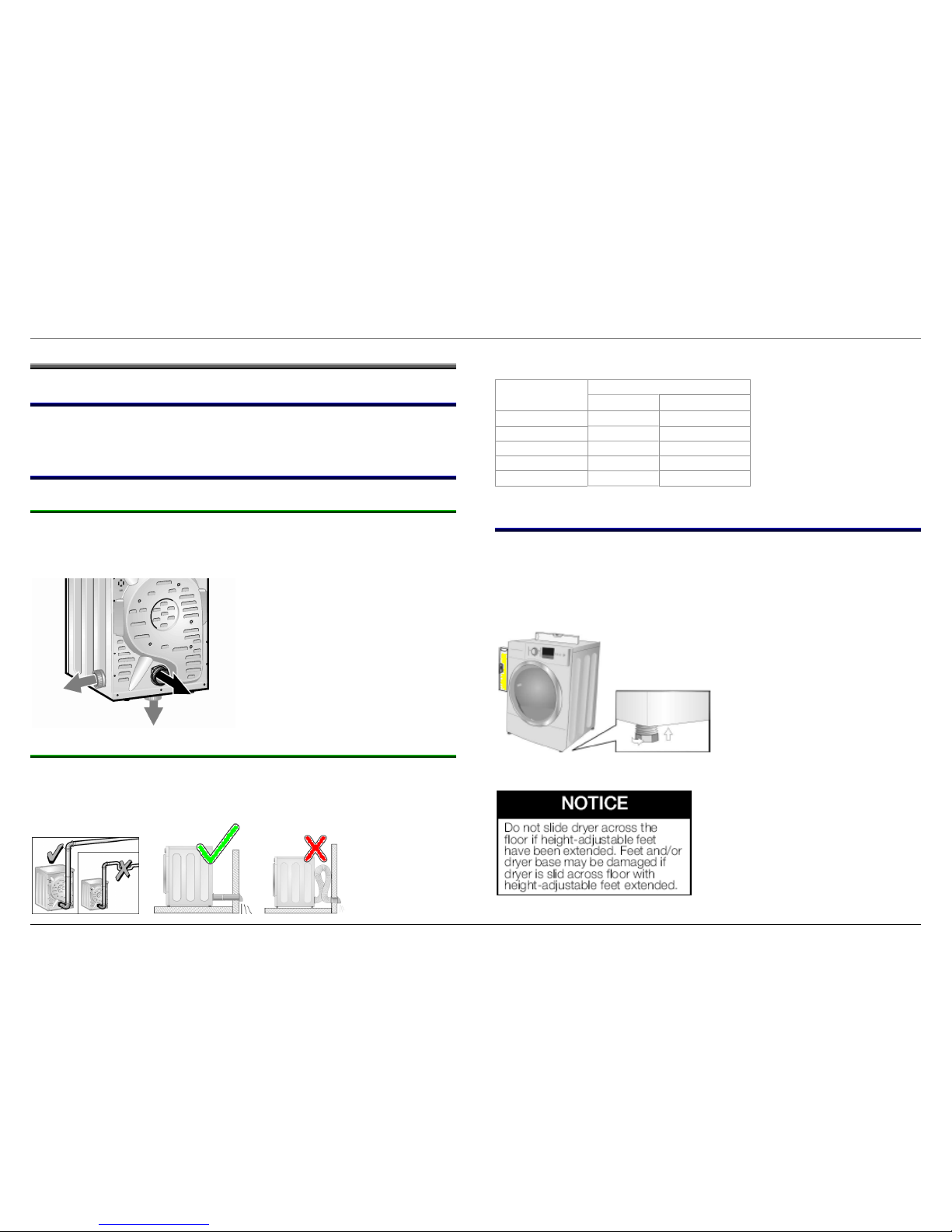
2.3 Feet (leveling legs)
Using a level front to back and side to side, adjust feet (leveling legs)
until dryer is level. When moving dryers, screw in feet completely
before moving dryers to avoid damage.
To adjust feet (leveling
legs), rotate left to right to
lower dryer.
702_58300000143767_ara_en_a Page 3 of 33
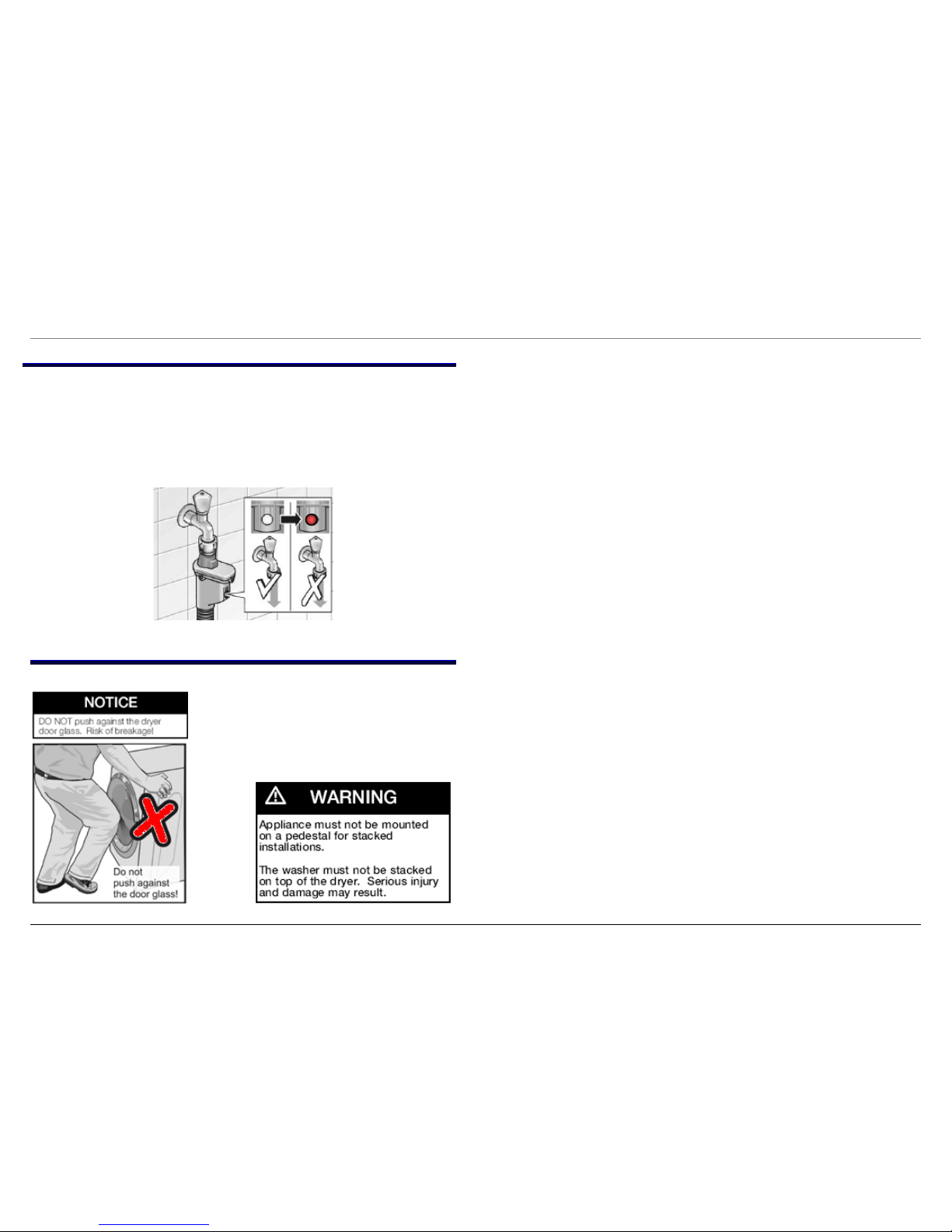
2.4 AQUASTOP® (aqua secure)
AQUASTOP® water inlet hoses prevent water from leaking. They
connect like standard hoses with no special installation needed. If an
inner hose ever should leak, the hose shuts off and it’s indicator
shows red. Hoses are one-time and must be replaced when
indicators are red.
2.5 General installation warnings
702_58300000143767_ara_en_a Page 4 of 33
3 OPERATION
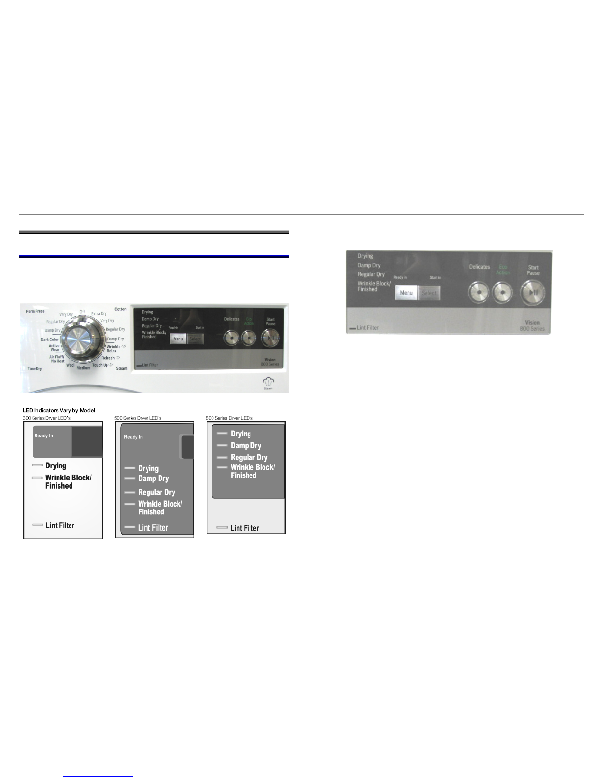
3.1 Controls
Controls are shown below. Rotate the knob to the desired drying
program and push the Start/Pause button.
There are option buttons for delicate fabrics and saving energy. Dryer
status is shown in LED’s at the left of the display.
702_58300000143767_ara_en_a Page 5 of 33

4 COMPONENTS
4.1 WTVC Gas Dryer Components
Basic components are control module, gas burner, gas igniter, flame
sensor, drive motor with fan, two NTC temperature sensors, two hilimit temperature protectors, moisture sensor and broken belt switch.
Gas dryers are set up for natural gas and can be converted to LP
using a kit (WTZ1280).
4.1.1 Gas burner assembly
Burner assemblies include an NTC temperature sensor and a
manually resettable hi-limit temperature protector. The NTC is
mounted at the rear of the assembly near where it attaches to the
vent.
BBuurrnneerr
cchhaammbbeerr
Gas
valve
BBuurrnneerr
((vveennttuurrii))
FFllaammee
sseennssoorr
IIggnniitteerr
HHii--lliimmiitt
BBuurrnneerr
cchhaammbbe
e
r
r
BBrrookkeenn bbeelltt
sswwiittcch
h
FFrroonntt ((bbeeaarriinngg))
sshhiieelld
d
MMootto
o
r
r
Fan
Gas
valve
Push
button to
reset Hi-limit
red
Hi-
limit
p
rotector.
702_58300000143767_ara_en_a Page 6 of 33
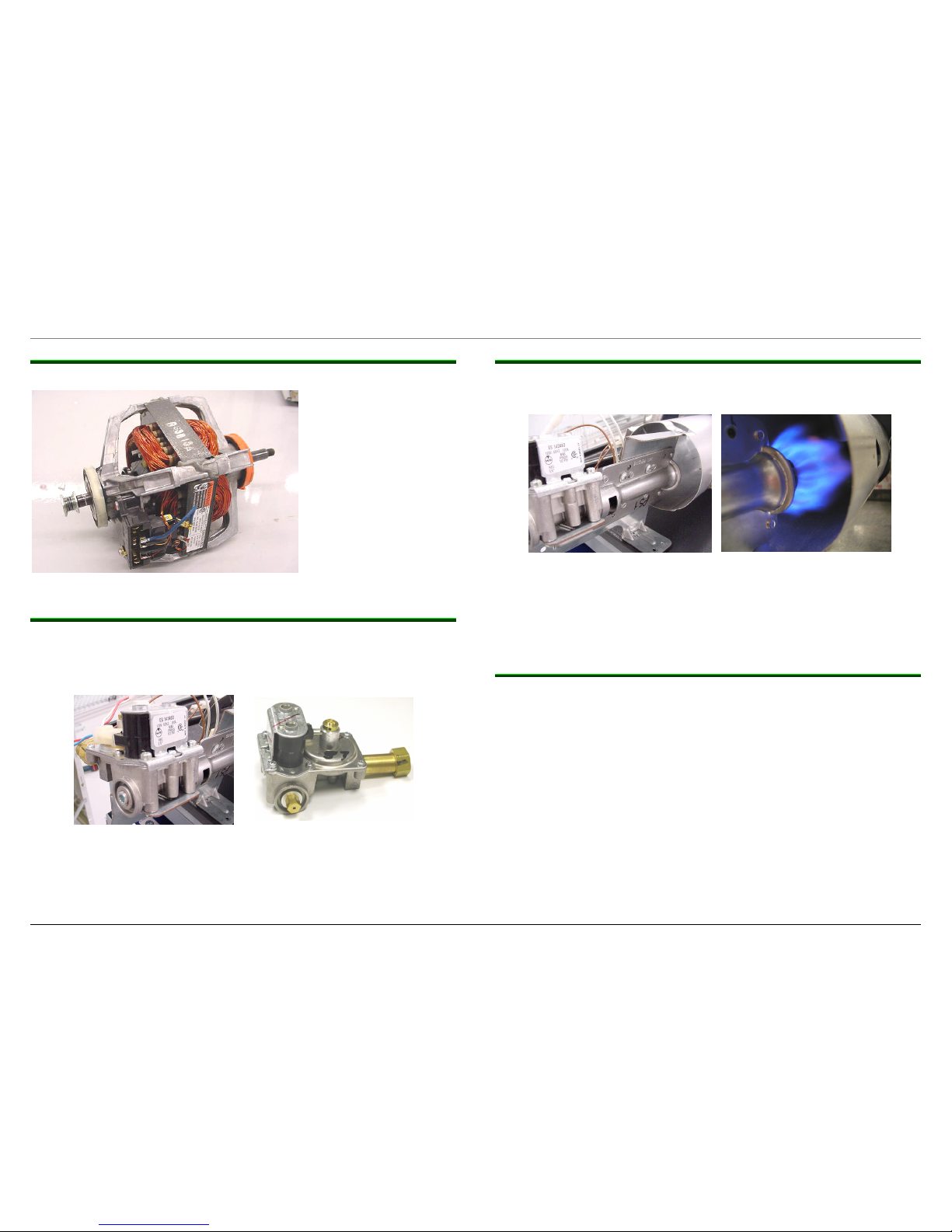
4.1.2 Drive motor
4.1.3 Gas valve
The gas valve, whether natural gas or LP, includes the appropriate
regulator and jet (orifice).
4.1.4 Burner
The burner mounts next to the gas valve jet (orifice). A burner ring is
used for natural gas dryers to optimize performance.
The gas dryer burner circuit runs through the motor & Hi-limit. The
connection through the motor cuts out the burner if the motor isn’t
running.
Motor is rated 120
VAC, 60 Hz, 1/3 HP
(248.5 W), 5.0 A,
1725 RPM, 40ºC
ambient, class B
insulation. It drives
the fan (in front) and
drum (in rear, using
pulley shown).
Drum
belt
pulley
Fan
wheel
shaft
Burner
GGaass vvaallvvee
4.1.5 Gas leak testing (using soapy water)
Whenever gas connections are changed or disturbed, they should be
checked for leaks using a soapy water solution.
1. Reconnect all gas connections and turn on the gas supply to
the dryer, using household gas inlet pressure.
2. Apply soapy water solution with a spray bottle. Spray union
and brass connections completely.
3. Watch connections carefully for about two minutes. If there is a
leak, bubbles will form in the area of the leak. Soapy water will
not stay on connections long, so spray more solution on them
when soapy water isn’t visible.
4. If bubbles form around the union, tighten the connection and
repeat steps 3 and 4 until no bubbles form.
702_58300000143767_ara_en_a Page 7 of 33

5. If bubbles form around the brass connector or on the gas valve
itself, replace the leaking valve with a new one and repeat
steps 3, 4 and 6.
6. Clean all soapy water solution with a rag or paper towel.
7. Never use a flame to check for gas leaks!
4.1.6 Igniter
Igniters glow after
4.1.7 Flame sensor
Flame sensors detect flame out in 30 – 60 seconds and direct the
igniter to reignite flames.
4.1.8 Lint screen sensors
The front (bearing) shield contains two sensors – accessible after the
lint screen is removed. Along with the heater NTC and hi-limit
protector, the lint screen NTC and hi-limit protector provide
temperature regulation and safety.
30 seconds, reliably igniting gas flames.
Igniters can be damaged if not handled with care.
Hi-limit NTC
Hi-limit
NTC
702_58300000143767_ara_en_a Page 8 of 33
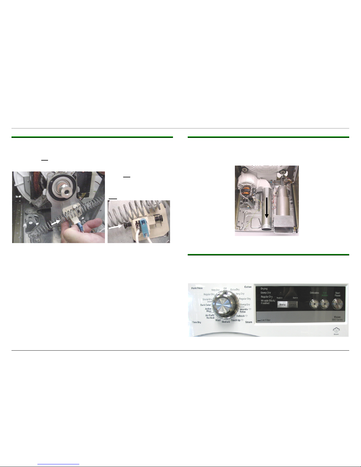
4.1.9 Broken belt switch
The broken belt switch prevents the dryer from running if the belt has
broken or been left disconnected. It must be manually reset (by
pushing the left plunger in (viewing rear of dryer) – the dryer will not
run if the switch hasn’t been reset.
4.1.10 Air exhaust duct
Air exhaust duct connects to the fan and allows exhausting through
the rear of dryers. Using kits (sales accessories), dryers can be
vented out the bottom or right side.
Fan
Vent
Push left plunger (toward
right) to reset broken belt
switch whenever drum or
belt has been removed for
any repair.
4.1.11 Fascia (control) panel
Fascia panel includes the knob, which is factory built into the panel
and cannot be obtained separately. Buttons can be obtained
separately.
702_58300000143767_ara_en_a Page 9 of 33
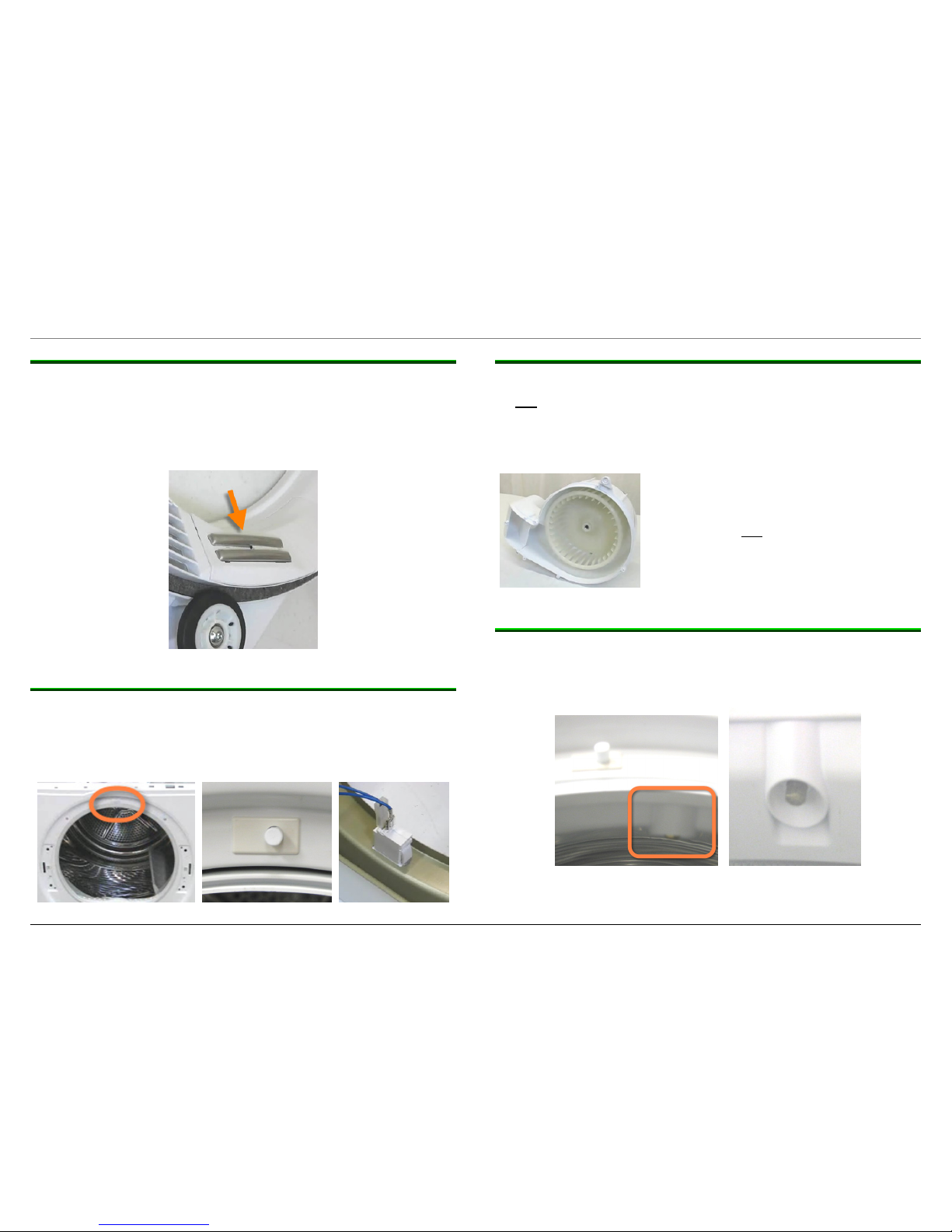
4.1.12 Moisture sensor
Moisture sensor consists of two electrodes (located just left of the lint
screen on the front bearing shield). Moisture from clothes completes
the circuit between the two sensors, showing clothes aren’t dry.
Placing the moisture sensor on the front shield eliminates sensors
inside drums and conductance brushes outside drums.
4.1.13 Door switch
Door switch engages the door, turning the light on and off and
notifying the dryer the door is closed for drying. To remove it, push
the two latches inward and slide the switch toward the front of the
dryer.
4.1.14 Fan wheel replacement
Even though WTVC and WTMC dryers use the same fan motor, they
do not use the same fan. Due to differing front bearing shield and lint
screen dimensions, air flows differently through the two dryers. Dryer
control software for each dryer is carefully matched to each fan to
provide the same drying results.
WTMC fan 491640 hasn’t been tested in
WTVC dryers and WTVC fan 648683
hasn’t been tested in WTMC dryers.
Fans must not be interchanged because
it will void the warranty, will affect the UL
certification, will affect drying and may
generate error codes.
4.1.15 Mist care (on selected dryers)
Mist care (on selected dryers) sprays a mist of water into dryers to
refresh clothing and relax any wrinkles. Water sprays occasionally as
needed, determined by the control.
702_58300000143767_ara_en_a Page 10 of 33
 Loading...