


Bosch HMV01.1E-W0030, HMV01.1E-W0075, HMV01.1R-W0065, HMV01.1R-W0018, HMV01.1E-W0120 Project Planning Manual
...
Industrial
Hydraulics
Electric Drives
and Controls
Linear Motion and
Assembly Technologies Pneumatics
Rexroth IndraDrive
Supply Units
Project Planning Manual
Service
Automation
Mobile
Hydraulics
R911299229
Edition 01
About this Documentation Rexroth IndraDrive
Title
Type of Documentation
Document Typecode
Internal File Reference
Record of Revisions
Copyright
Rexroth IndraDrive
Supply Units
Project Planning Manual
DOK-INDRV*-HMV-*******-PR01-EN-P
Document number 120-2400-B312-01/EN
Description Release
Notes
Date
DOK-INDRV*-HMV-*******-PR01-EN-P 01.2004 Project Planning Manual;
first edition
2004 Bosch Rexroth AG
Copying this document, giving it to others and the use or com munication
of the contents thereof without express authority, are forbidden. Offenders
are liable for the payment of damages. All rights are reserved in the event
of the grant of a patent or the registration of a utility model or design
(DIN 34-1).
Validity
Published by
Note
The specified data is for product description pur poses only and may not
be deemed to be guaranteed unless expres sly confirmed in the contract.
All rights are reserved with respect to the content of this docum entation
and the availability of the product.
Bosch Rexroth AG
Bgm.-Dr.-Nebel-Str. 2 • D-97816 Lohr a. Main
Telephone +49 (0)93 52/40-0 • Tx 68 94 21 • Fax +49 (0)93 52/40-48 85
http://www.boschrexroth.de/
Dept. EDC1/EDY1 (EH/US)
This document has been printed on chlorine-free bleached paper.
DOK-INDRV*-HMV-*******-PR01-EN-P

Rexroth IndraDrive Contents I
Contents
1 Introduction 1-1
1.1 About this Documentation.............................................................................................................1-1
Purpose of Documentation ...................................................................................................... 1-1
1.2 Introducing the Devices.................................................................................................................1-1
Features and Fields of Application ..........................................................................................1-1
Main Features..........................................................................................................................1-1
Basic Structure .........................................................................................................................1-2
Drive System............................................................................................................................1-3
Tests and Certifications ...........................................................................................................1-4
2 Important Directions for Use 2-1
2.1 Appropriate Use ............................................................................................................................2-1
Introduction ..............................................................................................................................2-1
Areas of Use and Application...................................................................................................2-2
2.2 Inappropriate Use..........................................................................................................................2-2
3 Safety Instructions for Electric Drives and Controls 3-1
3.1 Introduction ...................................................................................................................................3-1
3.2 Explanations.................................................................................................................................. 3-1
3.3 Hazards by Improper Use .............................................................................................................3-2
3.4 General Information ......................................................................................................................3-3
3.5 Protection Against Contact with Electr ical Par ts...........................................................................3-5
3.6 Protection Against Electric Shock by Protective Low Voltage (PELV) .........................................3-6
3.7 Protection Against Dangerous Movements ..................................................................................3-7
3.8 Protection Against Magnetic and Electromagnetic Fields During Operation and
Mounting .......................................................................................................................................3-9
3.9 Protection Against Contact with Hot Parts..................................................................................3-10
3.10 Protection During Handling and Mounting ..................................................................................3-10
3.11 Battery Safety.............................................................................................................................. 3-11
3.12 Protection Against Pressurized Systems....................................................................................3-11
4 Identifying and Checking the Delivered Components 4-1
4.1 Delivery of Components................................................................................................................4-1
Packaging ................................................................................................................................4-1
Accompanying Documents ......................................................................................................4-1
4.2 Scope of Delivery..........................................................................................................................4-1
Overview..................................................................................................................................4-1
Checking the Delivered Components ...................................................................................... 4-1
4.3 Component Designation................................................................................................................ 4-2
DOK-INDRV*-HMV-*******-PR01-EN-P

II Contents Rexroth IndraDrive
Type Plates on the Unit............................................................................................................4-2
4.4 Device Types ................................................................................................................................4-3
Type Code................................................................................................................................4-3
5 Transport and Storage 5-1
5.1 Transporting the Devices .............................................................................................................. 5-1
Conditions................................................................................................................................5-1
5.2 Storing the Devices.......................................................................................................................5-1
Conditions................................................................................................................................5-1
In Case of Long Storage Periods.............................................................................................5-1
6 Mechanical Mounting 6-1
6.1 Mounting Conditions .....................................................................................................................6-1
Ambient and Operating Conditions..........................................................................................6-1
Duty Capacity........................................................................................................................... 6-3
6.2 Mechanical Technical Data...........................................................................................................6-4
Dimensions ..............................................................................................................................6-4
Installation Orientation.............................................................................................................6-5
Arrangement of Components in the Control Cabinet...............................................................6-5
6.3 Cooling and Cooling Units ............................................................................................................6-7
Power Dissipation ....................................................................................................................6-7
Mounting Cooling Units............................................................................................................6-8
7 Electrical Installation 7-1
7.1 General Information ......................................................................................................................7-1
7.2 Interference Elimination and EMC ................................................................................................ 7-2
Interference Elimination...........................................................................................................7-2
10 Rules for EMC-Correct Installation of Drives......................................................................7-3
Optimal EMC Installation .........................................................................................................7-5
7.3 Electrical Data...............................................................................................................................7-7
HMV01.1E-W0030, -W0075, -W0120...................................................................................... 7-7
HMV01.1R-W0018, -W0045, -W0065 .....................................................................................7-8
Control Voltage ........................................................................................................................7-9
7.4 Complete Connection Diagram...................................................................................................7-10
7.5 Connecting Cables and Rails...................................................................................................... 7-11
Connections (Power Section) ................................................................................................7-11
Control Voltage (+24 V, 0 V)..................................................................................................7-15
DC Bus (L+, L-)......................................................................................................................7-17
PE Connection of Power Supply............................................................................................7-19
PE Connection, Power Supply Unit and Neighboring Device................................................ 7-20
X1, Bus Module......................................................................................................................7-21
X2, RS232..............................................................................................................................7-22
X3, Mains Connection............................................................................................................7-23
X31, Connection for Messages.............................................................................................. 7-25
X32, Mains Contactor Control, DC Bus Short Circuit, Braking Resistor Threshold...............7-27
X33, Acknowledge Messages of Internal Ma ins Contac tor ...................................................7-29
DOK-INDRV*-HMV-*******-PR01-EN-P

Rexroth IndraDrive Contents III
X14, Mains Voltage Synchronization.....................................................................................7-30
7.6 Touch Guard ............................................................................................................................... 7-31
Cutouts...................................................................................................................................7-31
Mounting ................................................................................................................................7-32
8 Determination of Appropriate Power Supply Units 8-1
8.1 Introduction ...................................................................................................................................8-1
8.2 DC Bus Continuous Power...........................................................................................................8-1
8.3 DC Bus Peak Power .....................................................................................................................8-4
8.4 Regenerated Energy.....................................................................................................................8-5
8.5 Continuous Regenerated Power...................................................................................................8-6
8.6 Peak Regenerated Power.............................................................................................................8-7
8.7 Connected Load of the Supply Unit .............................................................................................. 8-8
9 Control Mains Contactor 9-1
9.1 Control Possibilities....................................................................................................................... 9-1
Shutdowns with Faulty Drive Electronics.................................................................................9-1
Braking with Emergenc y Stop or Power Failure ...................................................................... 9-1
9.2 Controlling the Supply Unit with Emergency Stop Relays ............................................................9-1
With DC Bus Dynamic Brake...................................................................................................9-1
Without DC Bus Dynamic Brake..............................................................................................9-4
9.3 Control via NC Controller .............................................................................................................. 9-6
10 Troubleshooting 10-1
10.1 General........................................................................................................................................10-1
10.2 Fault Diagnostics and Resetting Faults ......................................................................................10-1
10.3 Checking and Repairing the Unit ................................................................................................10-2
10.4 Replacing the Unit....................................................................................................................... 10-3
10.5 Diagnostic Display.......................................................................................................................10-4
11 Disposal and Environmental Protection 11-1
11.1 Disposal ......................................................................................................................................11-1
Products.................................................................................................................................11-1
Packaging Materials ............................................................................................................... 11-1
11.2 Environmental Protection............................................................................................................11-1
No Release of Hazardous Substances..................................................................................11-1
Materials Contained in the Produc ts......................................................................................11- 1
Recycling................................................................................................................................11-2
12 Service & Support 12-1
12.1 Helpdesk ..................................................................................................................................... 12-1
12.2 Service-Hotline............................................................................................................................ 12-1
12.3 Internet........................................................................................................................................12-1
12.4 Vor der Kontaktaufnahme... - Before contacting us....................................................................12-1
12.5 Kundenbetreuungsstellen - Sales & Service Facilities ...............................................................12-2
DOK-INDRV*-HMV-*******-PR01-EN-P

IV Contents Rexroth IndraDrive
13 Appendix 13-1
13.1 Connection of Supply Unit by Wires ...........................................................................................13-1
Supply Unit to the Left of the Drive Controller .......................................................................13-1
Supply Unit to the Right of the Drive Controller.....................................................................13-2
13.2 Stacked Devices .........................................................................................................................13-3
Counterclockwise Cable Routing........................................................................................... 13-3
Clockwise Cable Routing....................................................................................................... 13-4
13.3 Mains Connection .......................................................................................................................13-5
General ..................................................................................................................................13-5
Mains Supply Requirements.................................................................................................. 13-6
HMV01.1E..............................................................................................................................13-7
HMV01.1R..............................................................................................................................13-9
Fusing with Direct Mains Supply..........................................................................................13-13
13.4 Grounding the Power Supply System.......................................................................................13-13
13.5 Fault Current Protective Device................................................................................................13-14
13.6 Earth Leakage Monitor..............................................................................................................13-14
13.7 Chronological Sequence when Switching ON and OFF...........................................................13-15
When Switching On .............................................................................................................13-15
When Switching Off .............................................................................................................13-16
13.8 Auxiliary Components ............................................................................................................... 13-17
Mains Choke........................................................................................................................13-17
Mains Filter HFD..................................................................................................................13-19
14 Index 14-1
DOK-INDRV*-HMV-*******-PR01-EN-P

Rexroth IndraDrive Introduction 1-1
1 Introduction
1.1 About this Documentation
Purpose of Documentation
This documentation describes
• planning the mechanical control cabinet construction
• planning the electrical control cabinet construction
• logistical handling of the equipment
1.2 Introducing the Devices
Features and Fields of Application
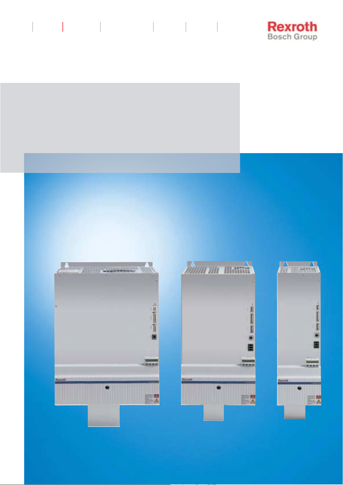
The supply unit …
• supplies IndraDrive M drive controllers with the required DC bus
voltage
• loops the 24 V control voltage of an external 24 V power supply
through to the drive controllers
• communicates with the drive controllers via a module bus
The supply units can be used for realizing a multitude of drive task s in
most diverse applications. F or these pur pos es ther e ar e 2 dif f er ent devic e
types (regenerative, non-regenerative) with graduated supply power
available.
Main Features
• design with regeneration back to the mains (HMV01.1R-Wxxxx)
and without regeneration back to the mains (HMV01.1E-Wxxxx)
• external 24 V supply required (signal processing not supplied from
DC bus)
• 3-phase mains connection (380V... 480V, +-10% 50Hz-60Hz)
• integrated mains contactor for E-Stop
• integrated braking resistor (bleeder) for feeding supply units
(HMV01.1E-Wxxxx)
• integrated emergency braking resistor for regenerative supply units
(HMV01.1R-Wxxxx)
DOK-INDRV*-HMV-*******-PR01-EN-P
1-2 Introduction Rexroth IndraDrive
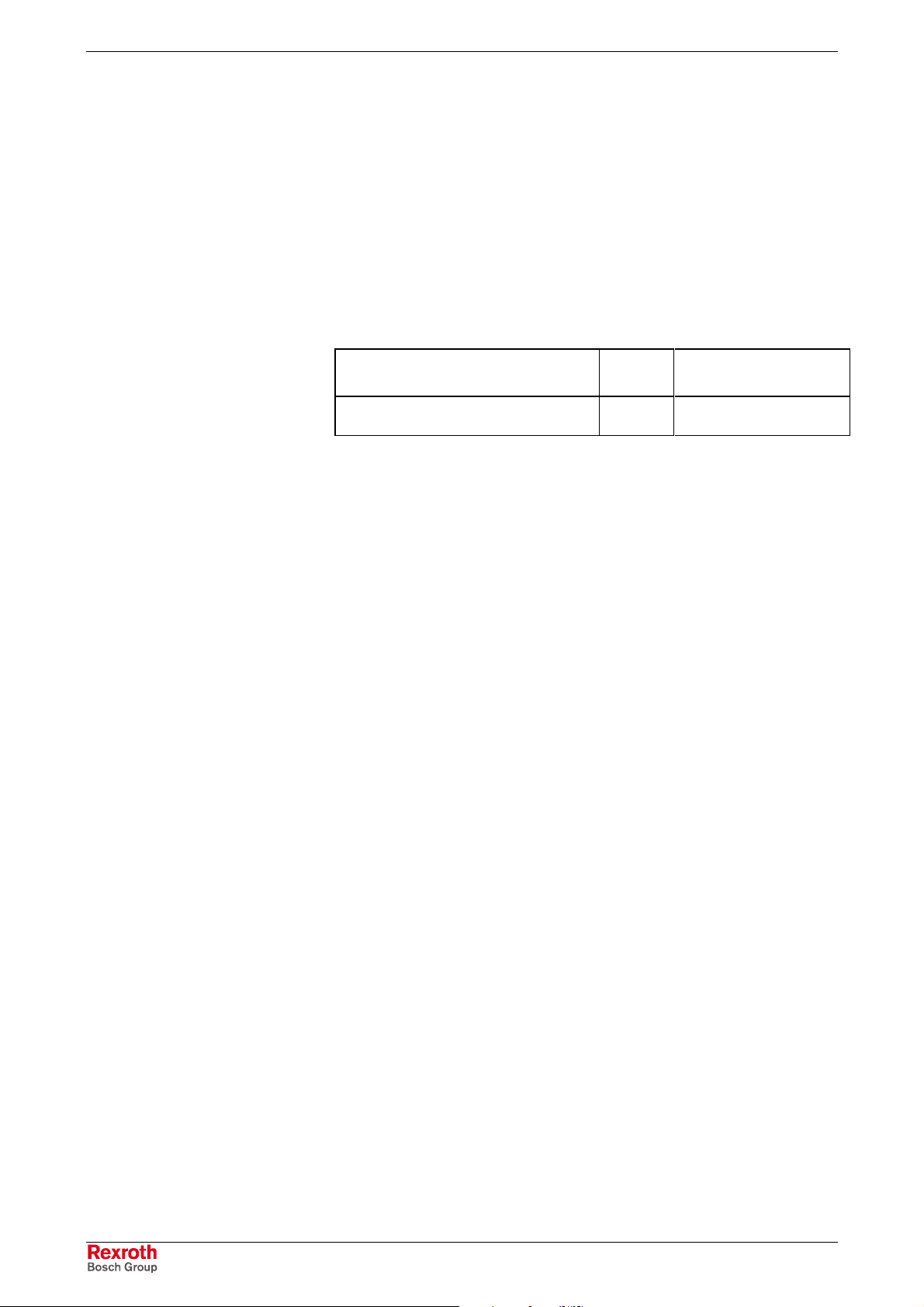
Basic Structure
Supply Unit
1
2
3
hmv_aufbau.fh7
1: Signal processing
2: Control panel (Display)
3: Power connections and control voltage connection
Fig. 1-1: Basic structure
Control Panel
The control panel is a separate part which is plugged on the supply unit.
The supply unit is supplied ex works complete with control panel.
01.F4002
Esc
Fig. 1-2: Standard control panel with sample display and control elements
• Operating status, command and error diagnoses, and warnings for
problems requiring attention are shown in the display.
• Using the four buttons, the commissioning operator or service
engineer can opt, in addition to master communication using the
commissioning tool or NC control, to display further error diagnoses.
Enter
DOK-INDRV*-HMV-*******-PR01-EN-P
Rexroth IndraDrive Introduction 1-3
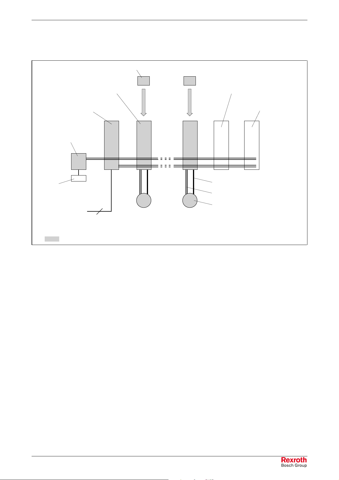
Drive System
The following figure shows the components of the drive system.
firmware
24 V supply unit
battery
components shown in gray are absolutely necessary
drive controller
supply unit
mains supply
DC bus resistor unit
DC bus capacitor unit
RKS - ready-made encoder cable
RKG - ready-made power cable
3
Fig. 1-3: Drive system
motor
Fa5147f1.fh7
DOK-INDRV*-HMV-*******-PR01-EN-P
1-4 Introduction Rexroth IndraDrive
Tests and Certifications
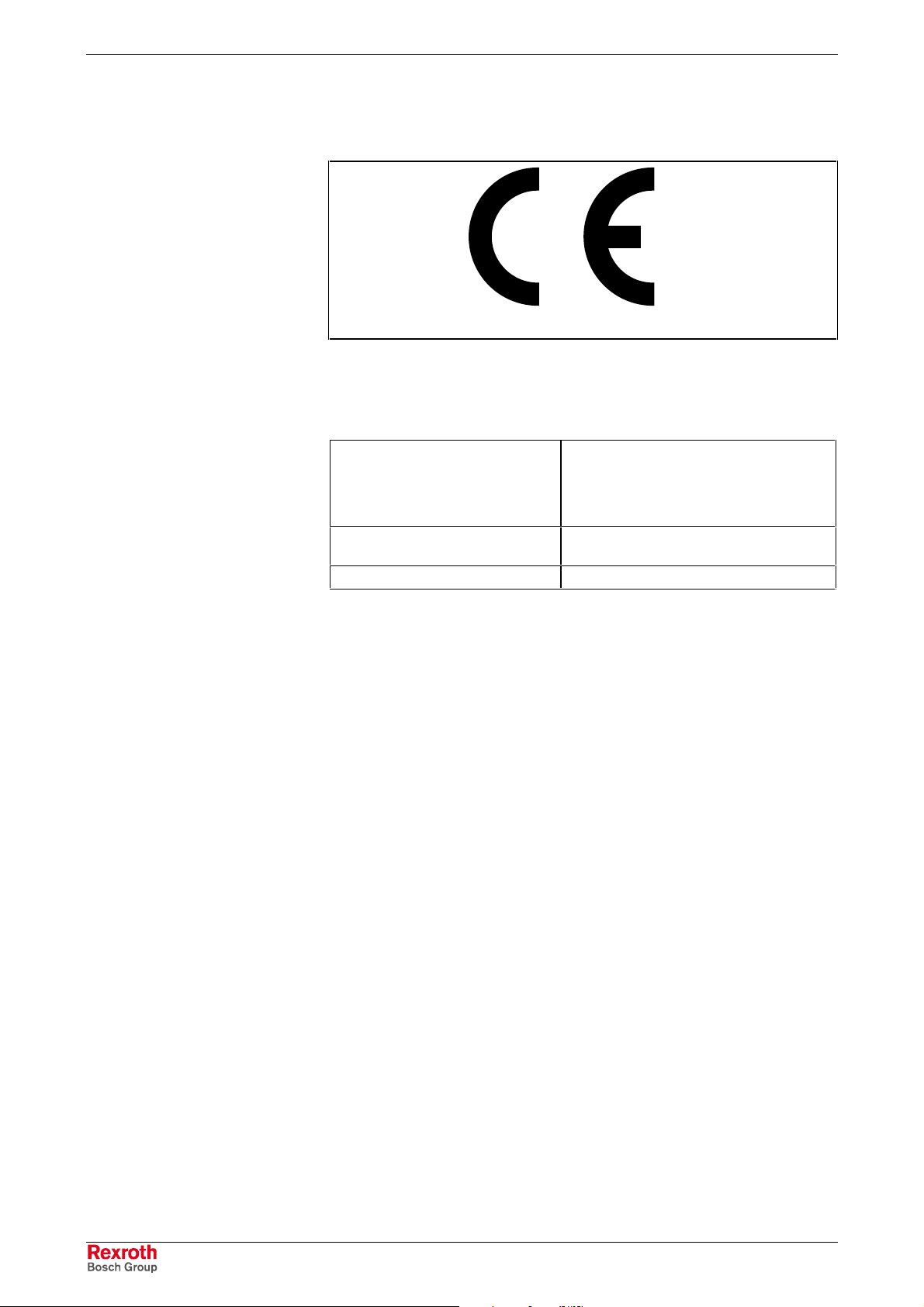
CE Mark
C-UL-US Listing
Tests
CEf1.fh7
Fig. 1-4: CE mark
In preparation
Insulation-high-voltage test in
accordance with EN50178
Separation between control and
power voltage circuits
Air gaps and leakage distances In accordance with EN50178
Fig. 1-5: Tests
Routine testing with DC 2230 V, 1 min
resp.
Routine testing with AC 1575 V, 1 min;
Power supply with 0,1 A short-circuit
current
Safe separation in accordance with
EN50178
DOK-INDRV*-HMV-*******-PR01-EN-P

Rexroth IndraDrive Important Directions for Use 2-1
2 Important Directions for Use
2.1 Appropriate Use
Introduction
Rexroth products represent state-of-the-art developments and
manufacturing. They are tested prior to delivery to ensure operating safety
and reliability.
The products may only be used in the manner that is defined as
appropriate. If they are used in an inappropriate manner, then situations
can develop that may lead to property damage or injury to personnel.
Note: Rexroth, as manufacturer, is not liable for any damages
resulting from inappropriate us e. In such cases , the guarantee
and the right to payment of damages resulting from
inappropriate use are forfeited. The user alone carries all
responsibility of the risks.
Before using Rexroth products, mak e sure that all the pre-requisites for
an appropriate use of the products are satisfied:
• Personnel that in any way, shape or form uses our products m ust first
read and understand the relevant safety instructions and be familiar
with appropriate use.
• If the product takes the form of hardware, then they must remain in
their original state, in other words, no structural changes are permitted.
It is not permitted to decompile software products or alter source
codes.
• Do not mount damaged or faulty products or use them in operation.
• Make sure that the products have been installed in the manner
described in the relevant documentation.
DOK-INDRV*-HMV-*******-PR01-EN-P

2-2 Important Directions for Use Rexroth IndraDrive
Areas of Use and Application
Supply units of Rexroth are designed to supply the Rexroth IndraDrive M
drive controllers.
Control and monitoring of the motors may require additional sensor s and
actors.
Note: The supply units may only be used with the accessories and
parts specified in this docum ent. If a com ponent has not been
specifically named, then it may not be either mounted or
connected. The same applies to cables and lines.
Operation is only permitted in the s pecified conf igurations and
combinations of com ponents using the software and f irmware
as specified in the relevant function descriptions.
The supply units may only be operated under the assembly, installation
and ambient conditions as described here (temperature, system of
protection, humidity, EMC requirements, etc.) and in the position
specified.
2.2 Inappropriate Use
Using the supply units outside of the above-referenced areas of
application or under operating conditions other than described in the
document and the technical data specified is defined as “inappropriate
use".
Supply units may not be used if
• they are subject to operating conditions that do not meet the above
• Rexroth has not specifically released them for that intended purpos e.
specified ambient conditions. This includes, for example, operation
under water, in the case of extreme temperature fluctuations or
extremely high maximum temperatures or if
Please note the specifications outlined in the general safety
instructions!
DOK-INDRV*-HMV-*******-PR01-EN-P
Rexroth IndraDrive Safety Instructions for Electric Drives and Controls 3-1
3 Safety Instructions for Electric Drives and Controls
3.1 Introduction
Read these instructions before the initial startup of the equipment in order
to eliminate the risk of bodily harm or material damage. Follow these
safety instructions at all times.
Do not attempt to install or start up this equipm ent without first r eading all
documentation provided with the product. Read and understand these
safety instructions and all user docum entation of the equipment prior to
working with the equipment at any time. If you do not have the user
documentation for your equipment, contact your local Rexroth
representative to send this documentation immediately to the person or
persons responsible for the safe operation of this equipment.
If the equipment is resold, rented or transferred or passed on to others,
then these safety instructions must be delivered with the equipment.
Improper use of this equipment, failure to follow
the safety instructions in this document or
tampering with the product , i ncluding disabling
WARNING
of safety devices, may result in material
damage, bodily harm, electric shock or even
death!
3.2 Explanations
The safety instructions describe the following degrees of hazard
seriousness in compliance with ANSI Z535. The degree of hazard
seriousness informs about the consequences resulting from noncompliance with the safety instructions.
Warning symbol with signal
word
DANGER
WARNING
CAUTION
Degree of hazard seriousness according
to ANSI
Death or severe bodily harm will occur.
Death or severe bodily harm may occur.
Bodily harm or material damage may occur.
DOK-INDRV*-HMV-*******-PR01-EN-P
Fig. 3-1: Hazard classification (according to ANSI Z535)
3-2 Safety Instructions for Electric Drives and Controls Rexroth IndraDrive
3.3 Hazards by Improper Use
High voltage and high discharge current!
Danger to life or severe bodily harm by electric
shock!
DANGER
Dangerous movements! Danger to life, severe
bodily harm or material damage by
unintentional motor movements!
DANGER
High electrical voltage due to wrong
connections! Danger to life or bodily harm by
electric shock!
WARNING
WARNING
CAUTION
CAUTION
Health hazard for persons with heart
pacemakers, metal implants and hearing aids in
proximity to electrical equipment!
Surface of machine housing could be extremely
hot! Danger of injury! Danger of burns!
Risk of injury due to improper handling! Bodily
harm caused by crushing, shearing, cutting and
mechanical shock or incorrect handling of
pressurized systems!
CAUTION
Risk of injury due to incorrect handling of
batteries!
DOK-INDRV*-HMV-*******-PR01-EN-P

Rexroth IndraDrive Safety Instructions for Electric Drives and Controls 3-3
3.4 General Information
• Bosch Rexroth AG is not liable for damages resulting from failure to
observe the warnings provided in this documentation.
• Read the operating, maintenance and safety instructions in your
language before starting up the machine. If you find that you cannot
completely understand the documentation for your product, please ask
your supplier to clarify.
• Proper and correct transport, storage, assembly and installation as
well as care in operation and maintenance are prerequisites for
optimal and safe operation of this equipment.
• O nly persons who are trained and qualified for the use and operation
of the equipment may work on this equipment or within its proximity.
• The persons are qualified if they have sufficient k nowledge of the
assembly, installation and operation of the equipm ent as well as an
understanding of all warnings and precautionary measures noted in
these instructions.
• Furthermore, they must be trained, instructed and qualified to
switch electrical circuits and equipment on and off in accordance
with technical safety regulations, to ground them and to mark them
according to the requirements of safe work practices. They must
have adequate safety equipment and be trained in first aid.
• Only use spare parts and accessories approved by the manufacturer.
• Follow all safety regulations and requirements for the specific
application as practiced in the country of use.
• The equipment is designed for installation in industrial machinery.
• The ambient conditions given in the product documentation must be
observed.
• Use only safety features and applications that are clearly and explicitly
approved in the Project Planning Manual.
For example, the following areas of use are not permitted: construction
cranes, elevators used for people or freight, devices and vehicles to
transport people, medical applications, refinery plants, transport of
hazardous goods, nuclear applications, applications sensitive to high
frequency, mining, food processing, control of protection equipment
(also in a machine).
• The information given in the documentation of the product with r egard
to the use of the delivered components contains only examples of
applications and suggestions.
The machine and installation manufacturer must
• make sure that the delivered components are suited for his
individual application and check the information given in this
documentation with regard to the use of the components,
• mak e sure that his application complies with the applicable safety
regulations and standards and carry out the required measures,
modifications and complements.
• Startup of the delivered components is only permitted once it is sure
that the machine or installation in which they are installed complies
with the national regulations, safety specifications and standards of the
application.
DOK-INDRV*-HMV-*******-PR01-EN-P

3-4 Safety Instructions for Electric Drives and Controls Rexroth IndraDrive
• Operation is only permitted if the national EMC regulations for the
application are met.
The instructions for installation in accordance with EMC requirements
can be found in the documentation "EMC in Drive and Control
Systems".
The machine or installation manufacturer is responsible for
compliance with the limiting values as prescribed in the national
regulations.
• Technical data, connections and operational conditions are specified in
the product documentation and must be followed at all times.
DOK-INDRV*-HMV-*******-PR01-EN-P
Rexroth IndraDrive Safety Instructions for Electric Drives and Controls 3-5
3.5 Protection Against Contact with Electrical Parts
Note: This section refers to equipment and drive components with
voltages above 50 Volts.
Touching live parts with voltages of 50 Volts and more with bar e hands or
conductive tools or touching ungrounded housings can be dangerous and
cause electric shock. In order to operate electrical equipment, certain
parts must unavoidably have dangerous voltages applied to them.
High electrical voltage! Danger to life, severe
bodily harm by electric shock!
DANGER
⇒ Only those trained and qualified to work with or on
electrical equipment are perm itted to operate, maintain
or repair this equipment.
⇒ Follow general construction and safety regulations when
working on high voltage installations.
⇒ Before switching on power the ground wire must be
permanently connected to all electrical units according
to the connection diagram.
⇒ Do not operate electrical equipment at any time, even
for brief measurements or tests, if the ground wire is not
permanently connected to the points of the com ponents
provided for this purpose.
⇒ Before work ing with electrical parts with voltage higher
than 50 V, the equipment must be disconnected from
the mains voltage or power supply. Make sure the
equipment cannot be switched on again unintended.
⇒ The following should be observed with electrical drive
and filter components:
⇒ W ait five (5) minutes af ter switching off power to allow
capacitors to discharge before beginning to work.
Measure the voltage on the capacitors before beginning
to work to make sure that the equipment is safe to
touch.
⇒ Never touch the electrical connection points of a
component while power is turned on.
⇒ Install the covers and guards provided with the
equipment properly before switching the equipment on.
Prevent contact with live parts at any time.
⇒ A residual-current-operated protective device (RCD)
must not be used on electric drives! Indirect contact
must be prevented by other means, for example, by an
overcurrent protective device.
⇒ Electrical components with exposed live parts and
uncovered high voltage terminals must be installed in a
protective housing, for example, in a control cabinet.
DOK-INDRV*-HMV-*******-PR01-EN-P
3-6 Safety Instructions for Electric Drives and Controls Rexroth IndraDrive
To be observed with electrical drive and filter components:
High electrical voltage on the housing!
High leakage current! Danger to life, danger of
injury by electric shock!
DANGER
⇒ Connect the electrical equipment, the housings of all
electrical units and motors permanently with the safety
conductor at the ground points before power is
switched on. Look at the connection diagram. This is
even necessary for brief tests.
⇒ Connect the safety conductor of the electrical
equipment always permanently and firmly to the
supply mains. Leakage current exceeds 3.5 mA in
normal operation.
⇒ Use a copper conductor with at least 10 mm² cross
section over its entire cour se for this saf ety conductor
connection! The cross section must not be smaller
than the cross section of a phase of the mains suppy
wire.
⇒ Prior to startups , even for brief tests, always connect
the protective conductor or connect with ground wire.
Otherwise, high voltages can occur on the housing
that lead to electric shock.
3.6 Protection Against Electric Shock by Protective Low Voltage (PELV)
All connections and terminals with voltages between 0 and 50 Volts on
Rexroth products are protective low voltages designed in accordance with
international standards on electrical safety.
High electrical voltage due to wrong
connections! Danger to life, bodily harm by
electric shock!
WARNING
⇒ Only connect equipment, electrical components and
cables of the protective low voltage type (PELV =
Protective Extra Low Voltage) to all terminals and
clamps with voltages of 0 to 50 Volts.
⇒ Only electrical circuits may be connected which are
safely isolated against high voltage circuits. Safe
isolation is achieved, for example, with an isolating
transformer, an opto-electronic coupler or when
battery-operated.
DOK-INDRV*-HMV-*******-PR01-EN-P

Rexroth IndraDrive Safety Instructions for Electric Drives and Controls 3-7
3.7 Protection Against Dangerous Movements
Dangerous movements can be caused by faulty control of the connected
motors. Some common examples are:
• improper or wrong wiring of cable connections
• incorrect operation of the equipment components
• wrong input of parameters before operation
• malfunction of sensors, encoders and monitoring devices
• defective components
• software or firmware errors
Dangerous movements can occur immediately after equipment is
switched on or even after an unspecified time of trouble-free operation.
The monitoring in the drive components will normally be sufficient to avoid
faulty operation in the connected drives. Regarding personal safety,
especially the danger of bodily injury and material damage, this alone
cannot be relied upon to ensure complete safety. Until the integrated
monitoring functions becom e effective, it must be assum ed in any case
that faulty drive movements will occur. The extent of faulty drive
movements depends upon the type of control and the state of operation.
DOK-INDRV*-HMV-*******-PR01-EN-P

3-8 Safety Instructions for Electric Drives and Controls Rexroth IndraDrive
Dangerous movements! Danger to life, risk of
injury, severe bodily harm or material damage!
DANGER
⇒ Ensure personal safety by means of qualified and
tested higher-level monitoring devices or measures
integrated in the installation. Unintended machine
motion is possible if monitoring devices are disabled,
bypassed or not activated.
⇒ Pay attention to unintended machine m otion or other
malfunction in any mode of operation.
⇒ Keep f ree and clear of the m achine’s range of m otion
and moving parts. Possible measures to prevent
people from accidentally entering the machine’s r ange
of motion:
- use safety fences
- use safety guards
- use protective coverings
- install light curtains or light barriers
⇒ Fences and coverings must be strong enough to
resist maximum possible momentum, especially if
there is a possibility of loose parts flying off.
⇒ Mount the emergency stop switch in the immediate
reach of the operator. Verify that the emer gency stop
works before startup. Don’t operate the m achine if the
emergency stop is not working.
⇒ Isolate the drive power connection by means of an
emergency stop circuit or use a starting lockout to
prevent unintentional start.
⇒ Make sure that the drives are brought to a safe
standstill before accessing or entering the danger
zone. Safe standstill can be achieved by switching off
the power supply contactor or by safe mechanical
locking of moving parts.
⇒ Secure vertical axes against falling or dropping after
switching off the motor power by, for example:
- mechanically securing the vertical axes
- adding an external braking/ arrester/ clamping
mechanism
- ensuring sufficient equilibration of the vertical axes
The standard equipment m otor brake or an external
brake controlled directly by the drive controller are
not sufficient to guarantee personal safety!
DOK-INDRV*-HMV-*******-PR01-EN-P
Rexroth IndraDrive Safety Instructions for Electric Drives and Controls 3-9
⇒ Dis connect electrical power to the equipment using a
master switch and secure the switch against
reconnection for:
- maintenance and repair work
- cleaning of equipment
- long periods of discontinued equipment use
⇒ Prevent the operation of high-frequency, remote
control and radio equipment near electronics circuits
and supply leads. If the use of such equipment cannot
be avoided, verify the system and the installation for
possible malfunctions in all possible positions of
normal use before initial startup. If neces sary, perform
a special electromagnetic c ompatibility (EMC) test on
the installation.
3.8 Protection Against Magnetic and Electromagnetic Fields During Operation and Mounting
Magnetic and electromagnetic fields generated near current-carrying
conductors and permanent m agnets in m otors represent a ser ious health
hazard to persons with heart pacemakers, metal implants and hearing
aids.
WARNING
Health hazard for persons with heart
pacemakers, metal implants and hearing aids in
proximity to electrical equipment!
⇒ Persons with heart pacemakers, hearing aids and
metal implants are not perm itted to enter the following
areas:
- Areas in which electrical equipm ent and parts are
mounted, being operated or started up.
- Areas in which parts of motors with permanent
magnets are being stored, operated, repaired or
mounted.
⇒ If it is necess ary for a person with a heart pacemak er
to enter such an area, then a doctor must be
consulted prior to doing so. Heart pacemakers that
are already implanted or will be implanted in the
future, have a considerable variation in their electric al
noise immunity. Therefore there are no rules with
general validity.
⇒ Persons with hearing aids, metal implants or metal
pieces must consult a doctor before they enter the
areas described above. Otherwise, health hazards will
occur.
DOK-INDRV*-HMV-*******-PR01-EN-P
3-10 Safety Instructions for Electric Drives and Controls Rexroth IndraDrive
3.9 Protection Against Contact with Hot Parts
Housing surfaces could be extremely hot!
Danger of injury! Danger of burns!
⇒ Do not touch housing surfaces near sources of heat!
CAUTION
Danger of burns!
⇒ After switching the equipment off, wait at least ten (10)
minutes to allow it to cool down before touching it.
⇒ Do not touch hot parts of the equipment, such as
housings with integrated heat sinks and resistors.
Danger of burns!
3.10 Protection During Handling and Mounting
Under certain conditions, incorrect handling and mounting of parts and
components may cause injuries.
CAUTION
Risk of injury by incorrect handling! Bodily
harm caused by crushing, shearing, cutting and
mechanical shock!
⇒ Observe general installation and safety instructions
with regard to handling and mounting.
⇒ Use appropriate mounting and transport equipment.
⇒ Take precautions to avoid pinching and crushing.
⇒ Use only appropriate tools. If specified by the product
documentation, special tools must be used.
⇒ Use lifting devices and tools correctly and safely.
⇒ For safe protection wear appropriate protective
clothing, e.g. safety glasses, safety shoes and saf ety
gloves.
⇒ Never stand under suspended loads.
⇒ Clean up liquids from the floor imm ediately to prevent
slipping.
DOK-INDRV*-HMV-*******-PR01-EN-P
Rexroth IndraDrive Safety Instructions for Electric Drives and Controls 3-11
3.11 Battery Safety
Batteries contain reactive chemicals in a solid housing. Inappropriate
handling may result in injuries or material damage.
Risk of injury by incorrect handling!
⇒ Do not attempt to reactivate discharged batteries by
heating or other methods (danger of explosion and
CAUTION
Note: Be aware of environmental protection and disposal! The
batteries contained in the product should be considered as
hazardous material for land, air and sea trans port in the sense
of the legal requirements (danger of explosion). Dispose
batteries separately from other waste. Observe the legal
requirements in the country of installation.
cauterization).
⇒ Never charge non-chargeable batteries (danger of
leakage and explosion).
⇒ Never throw batteries into a fire.
⇒ Do not dismantle batteries.
⇒ Do not damage electrical com ponents installed in the
equipment.
3.12 Protection Against Pressurized Systems
Certain motors and drive controllers, corr esponding to the information in
the respective Project Planning Manual, must be provided with
pressurized media, such as compressed air, hydraulic oil, cooling fluid
and cooling lubricant supplied by external systems. Incor rect handling of
the supply and connections of pressurized systems can lead to injuries or
accidents. In these cases, improper handling of external supply systems,
supply lines or connections can cause injuries or material damage.
Danger of injury by incorrect handling of
pressurized systems!
⇒ Do not attempt to disassemble, to open or to cut a
CAUTION
pressurized system (danger of explosion).
⇒ Observe the operation instructions of the respective
manufacturer.
⇒ Before disassembling pressurized systems, release
pressure and drain off the fluid or gas.
⇒ Use suitable protective clothing (for example safety
glasses, safety shoes and safety gloves)
⇒ Remove any fluid that has leaked out onto the floor
immediately.
DOK-INDRV*-HMV-*******-PR01-EN-P
Note: Environmental protection and disposal! T he m edia used in the
operation of the pressurized system equipment may not be
environmentally compatible. Media that are damaging the
environment must be dis posed separately from norm al waste.
Observe the legal requirements in the country of installation.

3-12 Safety Instructions for Electric Drives and Controls Rexroth IndraDrive
Notes
DOK-INDRV*-HMV-*******-PR01-EN-P
Rexroth IndraDrive Identifying and Checking the Delivered Components 4-1
4 Identifying and Checking the Delivered
Components
4.1 Delivery of Components
Packaging
Packaging Units
Packaging Labels
Disposal of Packaging Material
The components are supplied in separate packaging units.
The content of the packed components and the order number may be
identified using the adhesive barcode label on the packaging.
See chapter 11 "Disposal and Environmental Protection".
Accompanying Documents
A delivery note in duplicate can be found in an envelope on one of the
packages supplied. No other accompanying documents are provided.
The total number of c ontainers supplied is recorded on the delivery note
or consignment note.
4.2 Scope of Delivery
Overview
as standard optional
touch guard rails for connecting the DC bus
grounding bracket rails for connecting the control voltage
connector X31, X32, X33
safety instructions (brochure; DOK-
GENERAL-DRIVE******-SVSx-MS-P)
Fig. 4-1: Scope of delivery
Checking the Delivered Components
Please immediately check whether the delivered components are:
• complete
• correct
• intact
DOK-INDRV*-HMV-*******-PR01-EN-P
4-2 Identifying and Checking the Delivered Components Rexroth IndraDrive
4.3 Component Designation
Each drive component is identified by a type designation.
A type plate is attached to all units, including the motor.
A label (cable marker) is wrapped round the ready-made cable. The type
designation and length are indicated on this label. (The designation for the
cable itself, without connector, is printed on the cable sheath.)
The identification of acc essories packed in bags is either printed on the
bag or indicated in an accompanying note.
Type Plates on the Unit
Fig. 4-2: Type plate arrangement
hmv_typenschild.fh7
DOK-INDRV*-HMV-*******-PR01-EN-P
Rexroth IndraDrive Identifying and Checking the Delivered Components 4-3
4.4 Device Types
Type Code
Note: The following figure illustrates the bas ic structure of the type
code. Your sales representative will help with the current
status of available versions.
Abbrev.
Column
Example:
1. Product
1.1 HMV . . . . . . . . . = HMV
2. Line
2.1 1 . . . . . . . . . . . . . . . . . . . = 01
1234 6789105 1234 6789205 1234 6789305 1234 6789405
HMV01 . 1E -W0030 -A- 07-NNNN
3. Design
3.1 1 . . . . . . . . . . . . . . . . . . . . . . . . . = 1
4. Power supply
4.1 feeded . . . . . . . . . . . . . . . . . . . . . . = E
4.2 regenerative. . . . . . . . . . . . . . . . . . . = R
5. Cooling mode
5.1
Air, internal (through integrated blower)
6. Rated output
Rated output Power supply Code
[ KW ] E R
with choke
30 X - 0030
45 - X 0045
7. Protection mode
7.1 IP 20 . . . . . . . . . . . . . . . . . . . . . . . . . . . . . . . . . . . . . . . = A
8. DC-bus nominal voltage
8.1 DC 700V. . . . . . .. . . . . . . . . . . . . . . . . . . . . . . . . . . . . . . . . . .= 07
9. Other design
9.1 none . . . . . . . . . . . . . . . . . . . . . . . . . . . . . . . . . . . . . . . . . . . . . . . . = NNNN
10. Standard reference
Standard Titel Edition
DIN EN 60529 Degrees of protection provided by enclosures (IP-Code) 2000-09
= W
DOK-INDRV*-HMV-*******-PR01-EN-P
Fig. 4-3: Type code

4-4 Identifying and Checking the Delivered Components Rexroth IndraDrive
Notes
DOK-INDRV*-HMV-*******-PR01-EN-P
Rexroth IndraDrive Transport and Storage 5-1
5 Transport and Storage
5.1 Transporting the Devices
Conditions
temperature -25 ... 70 °C
relative humidity 5 ... 95%;
climatic category 2K3
absolute humidity 1 ... 60 g/m
climatic category 2K3
moisture condensation not allowed
icing not allowed
Shock check not in operation
according to EN 60068-2-27
Fig. 5-1: Conditions for transport
Halve sine in 3 axis:
10g / 11ms
3
5.2 Storing the Devices
Conditions
temperature -25 ... 55 °C
relative humidity 5 ... 95%;
absolute humidity 1 ... 29 g/m
moisture condensation not allowed
icing not allowed
Fig. 5-2: Conditions for storage
In Case of Long Storage Periods
The power supply units contain sensitive electrolytic capacitors.
Therefore, in the case of long storage periods, operate the power supply
units once a year for at least 1 hour with power on (DC bus voltage mus t
be applied).
climatic category 1K3
3
climatic category 1K3
DOK-INDRV*-HMV-*******-PR01-EN-P

5-2 Transport and Storage Rexroth IndraDrive
Notes
DOK-INDRV*-HMV-*******-PR01-EN-P
 Loading...