

Bosch D8108A, D8108A-CE Installation Manual
© 2017 Bosch Security Systems, Inc. 130 Perinton Parkway Fairport, NY 14450
Bosch Sicherheitssysteme GmbH Robert-Bosch-Ring 5 85630 Grasbrunn Germany
Dimensions 16 in. x 16 in. x 3.5 in. (41 cm x 41 cm x 9 cm)
Color Grey
Compatible Tamper Switches D110 (P/N: 4998137947) or
ICP-EZTS (P/N: F01U217038)
D101 Lock and Key (included) (P/N: 4998800200)
4 | D8108A Specifications
Dimensions 16 in. x 16 in. x 3.5 in. (41 cm x 41 cm x 9 cm)
Color Grey
Compatible Tamper Switches D110 (P/N: 4998137947) or
ICP-EZTS (P/N: F01U217038)
D101 Lock and Key (included) (P/N: 4998800200)
Transformer (included) (P/N: F01U166215)
5 | D8108A-CE Specifications
Region Certification
USA UL 294 - Access Control System Units
UL 365 - Police Station Connected Burglar Alarm Units and Systems
UL 609 - Local Burglar Alarm Units and Systems
UL 864 - Control Units and Accessories for Fire Alarm Systems
UL 985 - Household Fire Warning System Units
UL 1023 - Household Burglar-Alarm System Units
UL 1076 - Proprietary Burglar Alarm Units and Systems
UL 1610 - Central Station Burglar Alarm Units
CSFM - California Office of The State Fire Marshal
FDNY
CA Canada CAN/ULC S303 - Local Burglar Alarm Units and Systems
CAN/ULC S304 - Signal Receiving Centre and Premise Alarm Control Units
ULC-ORD C1023 - Household Burglar Alarm System Units
6 | D8108A certifications
Region Certification
Europe CE
7 | D8108A-CE certifications
en Installation Guide
Attack Resistant Enclosure
D8108A/D8108A-CE
Copyright
This document is the intellectual property of Bosch Security Systems, Inc. and is
protected by copyright. All rights reserved.
Trademarks
All hardware and software product names used in this document are likely to be
registered trademarks and must be treated accordingly.
Bosch Security Systems, Inc. product manufacturing dates
Use the serial number located on the product label and refer to the Bosch Security
Systems, Inc. website at
http://www.boschsecurity.com/datecodes/.
4998132018 | 07 | 03.2017 | 2
© 2017 Bosch Security Systems, Inc. 130 Perinton Parkway Fairport, NY 14450
Bosch Sicherheitssysteme GmbH Robert-Bosch-Ring 5 85630 Grasbrunn Germany
1 | Overview
The D8108A/D8108A-CE Attack Resistant Enclosures house many Bosch Security
Systems, Inc. control panels. When housed in a D8108A/D8108A-CE, a listed control
panel can be used in a high-security mercantile alarm application. For specific control
panel applications, refer to the operation and installation manual for the control panel.
The D8108A-CE enclosure includes a transformer for CE installations.
3.55 in.
16 in.
16 in.
1
4
3
2
5
6
3
6
3
Figure 1.1: Mounting the enclosure and installing accessories
Callout ― Description
1 ― Tamper switches (2)
2 ― 1 in. (2.5 cm) 6-32 screws (6) and nuts (6) for the tamper switches
3 ― 7/8 in. (2.2 cm) 8-32 machine screws (5)
4 ― D101 Lock and key (P/N: 4998800200)
5 ― Tamper switch mounting holes
6 ― Knockouts
2 | Installation
Wire the D8108A-CE transformer to the control panel after completing the instructions
in Section 2.
2
L N
3
4
USB POWER
STATUS
B
A
S
E
L
I
N
K
T
ETHERNETUSB
EARTH GROUND
COMMON
BATTERY ( - )
+ AUX POWER
BATTERY ( + )
CLASS 2
16.5 VAC 40 VA 60 Hz
TRANSFORMER
10
9
8
7
6
5
4
3
2
1
WARNING!
Multi-Battery
installation requires
Model D122 or D122L
Dual Battery Harness.
Improper installation
can be a fire hazard
.
Low 12.1 VDC
Load Shed 10.2 VDC
OUTPUT
B (2)
OUTPUT
A (1)
OUTPUT
C (3)
1
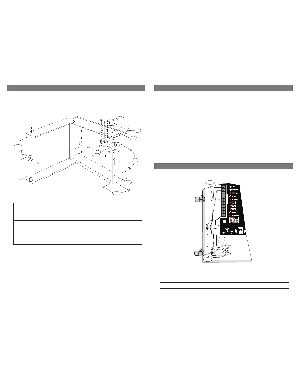
Figure 3.1: Wiring the D8108A-CE
Callout ― Description
1 ― Low voltage AC
2 ― Ground wire connection
3 ― AC IN
4 ― Wire tie the AC IN wires to the enclosure lance
3 | Wire a D8108A-CE to a control panel
Two knockouts in the enclosure base (one in the top, the other in the bottom)
accommodate ¾ in. (2 cm) conduit. The enclosure door is slotted to enable conduit
access.
1. Attach the lead wires to the terminals on the two tamper switches and wire them in
series with an EOL resistor.
2. Using the supplied hardware, screw the tamper switches to the enclosure (screws on
the outside and the nuts on the inside).
3. Mount the lock for UL Burglary and Fire applications on the enclosure door.
4. Mount the enclosure to a hard, flat surface.
5. Mount the control panel (with the mounting skirt) inside the enclosure.
6. Wire, program, and test the control panel and related peripheral equipment.
7. Wire the tamper switches to a control panel protective zone or point input.
8. Close the enclosure door.
9. Install the supplied 7/8 in. (2.2 cm) 8-32 screws in the five locations, securing the
door to the base and making the enclosure attack resistant.
 Loading...