

Bosch D8024, D10024A Operation And Installation Manual
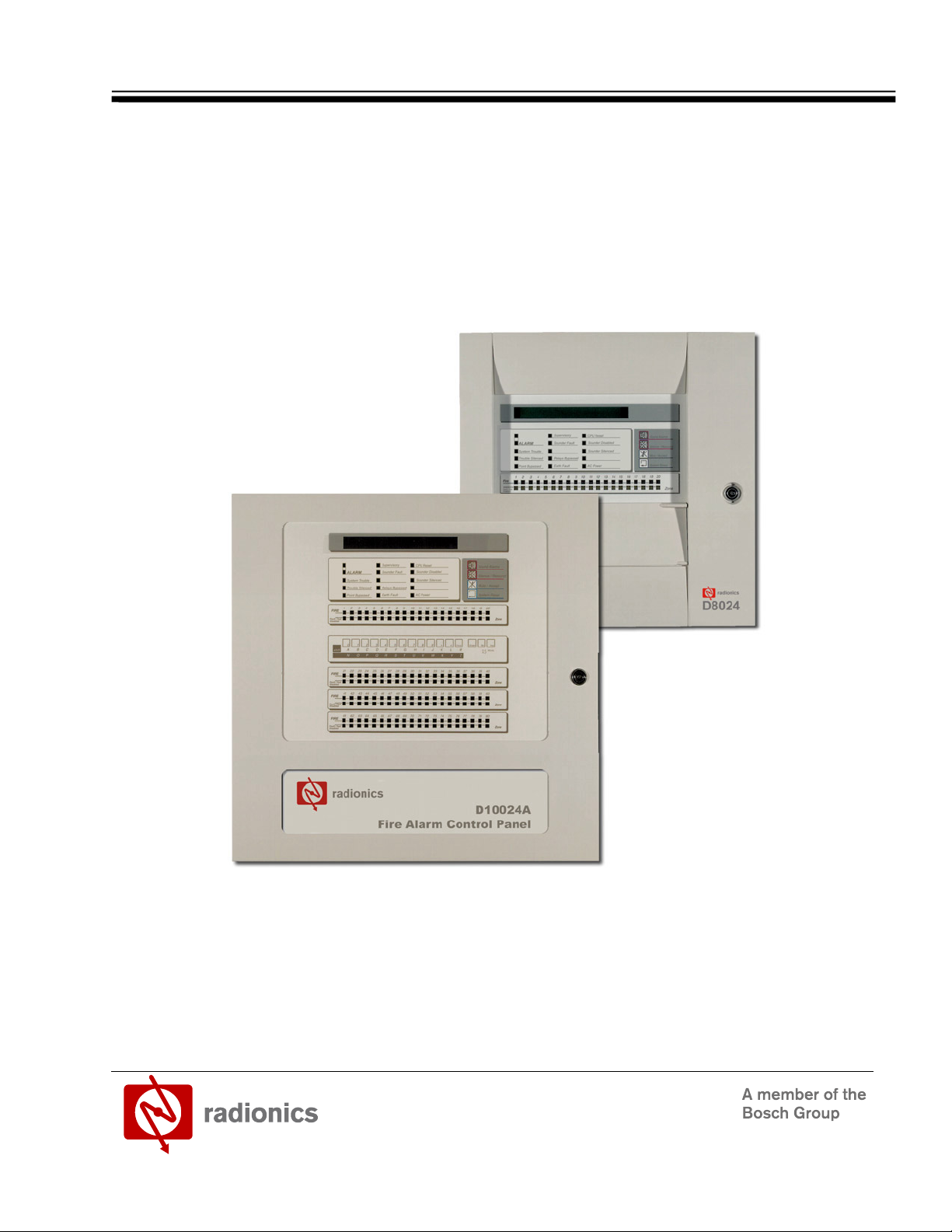
D8024/D10024A Fire Alarm Control Panels
Operation and Installation Guide

D8024/D10024A Operation and Installation Guide
50616B Page 2 © 2002 Radionics

D8024/D10024A
Contents
1.0 Introduction......................................................................................................... 7
1.1 Other Literature Referenced ............................................................................................................................. 7
1.2 Documentation Conventions............................................................................................................................. 7
1.2.1 Type Styles Used in this Manual ...................................................................................................................... 7
1.2.2 Tips, Important Notes, Cautions and Warnings................................................................................................ 7
1.3 UL/National Approvals ...................................................................................................................................... 8
1.4 EMC Compatibility ............................................................................................................................................ 8
2.0 D8024/D10024A Overview .................................................................................. 9
D8024 ............................................................................................................................................................... 9
D10024A........................................................................................................................................................... 9
2.1 Specifications.................................................................................................................................................. 10
2.1.1 D8024 ............................................................................................................................................................. 10
2.1.2 D10024A......................................................................................................................................................... 10
2.2 Level Definition ............................................................................................................................................... 11
2.3 User Passwords.............................................................................................................................................. 11
3.0 Installation......................................................................................................... 13
3.1 Front Panel Controls....................................................................................................................................... 13
3.1.1 Control Keys ................................................................................................................................................... 13
3.1.2 Alphanumeric/Interactive Control Keys........................................................................................................... 14
3.1.3 System Control LED Indications ..................................................................................................................... 14
3.1.4 Zone LED Displays ......................................................................................................................................... 15
3.1.5 LCD Display Indications.................................................................................................................................. 15
3.2 Memory Lock .................................................................................................................................................. 16
3.3 Enabling Level 2 or Level 3 Access................................................................................................................ 16
3.3.1 Selecting the commissioning option ............................................................................................................... 16
3.4 Overview of Menu Structure ........................................................................................................................... 17
4.0 D8024/D10024A Control Panel Wiring............................................................. 19
4.1 Step 1 – General Setup .................................................................................................................................. 19
4.2 Step 2 – Configure Each Signaling Loop........................................................................................................ 19
4.3 Step 3 – Configure Peripherals (if required) ................................................................................................... 19
4.4 Step 4 – Configure Outputs (NACs and relays).............................................................................................. 19
4.5 Step 5 – Configure Day Mode Operation (If required)....................................................................................19
4.6 Step 6 – Configure Network Options (If required) .......................................................................................... 19
4.7 Step 7 – Commence Normal Operation.......................................................................................................... 20
5.0 Programming the D8024/D10024A .................................................................. 21
5.1 Accessing the Configure Option ..................................................................................................................... 21
5.2 Signaling Loops ..............................................................................................................................................21
5.3 Auto Learn ...................................................................................................................................................... 21
5.3.1 Zones .............................................................................................................................................................. 22
5.3.2 Devices ........................................................................................................................................................... 22
5.4 Changing Device Information ......................................................................................................................... 23
5.5 Location Text .................................................................................................................................................. 23
5.5.1 Numbers ......................................................................................................................................................... 23
5.5.2 Letters ............................................................................................................................................................. 23
5.5.3 Keywords ........................................................................................................................................................ 23
5.5.3.1 Device Events................................................................................................................................................. 24
5.5.3.2 Alarm Thresholds (Device Sensitivity)............................................................................................................ 24
5.5.3.3 Restoring Sensitivity Defaults ......................................................................................................................... 25
5.5.3.4 Device Actions ................................................................................................................................................ 25
5.5.3.5 Groups / Group Disablements ........................................................................................................................ 25
Group Assignment............................................................................................................................ 26
Group Disablement Input ................................................................................................................. 26
D8024/D10024A Operation and Installation Guide
© 2002 Radionics Page 3 50616B

D8024/D10024A
Contents
Operation..........................................................................................................................................26
5.6 Peripherals...................................................................................................................................................... 26
5.6.1 Auto Learn....................................................................................................................................................... 26
5.6.2 Zones .............................................................................................................................................................. 27
5.6.3 Devices ...........................................................................................................................................................27
5.6.3.1 Changing Device Information.......................................................................................................................... 28
5.7 NACs – Notification Appliance Circuits (NAC)................................................................................................ 28
5.7.1 NAC Output Types.......................................................................................................................................... 28
5.7.2 Allocating NACs .............................................................................................................................................. 28
5.7.3 Detector loop addressable NAC circuit controller units (SCC) .......................................................................29
5.7.4 Peripheral loop addressable NAC circuit controller units................................................................................ 30
5.8 Relays ............................................................................................................................................................. 30
5.8.1 Fault Relay...................................................................................................................................................... 30
5.9 PC Programming ............................................................................................................................................ 30
6.0 System Startup.................................................................................................. 31
6.1 Inspect Option................................................................................................................................................. 31
7.0 Operating the D8024/D10024A ......................................................................... 33
7.1 Time / Date Option.......................................................................................................................................... 33
7.2 Time / Date...................................................................................................................................................... 33
7.3 System (Clear Memory) .................................................................................................................................. 33
7.4 Crystal ............................................................................................................................................................. 33
8.0 Fire Safety.......................................................................................................... 35
9.0 Power Supplies.................................................................................................. 37
10.0 System Worksheet ............................................................................................39
11.0 Troubleshooting ................................................................................................ 41
11.1 Day Modes ...................................................................................................................................................... 41
11.2 Delayed Mode................................................................................................................................................. 41
11.2.1 Commissioning Delayed Mode ....................................................................................................................... 42
11.3 Sensitivity Mode.............................................................................................................................................. 43
11.3.1 Commissioning Sensitivity Mode .................................................................................................................... 43
11.4 Verification Mode ............................................................................................................................................43
11.4.1 Commissioning Verification Mode................................................................................................................... 44
12.0 Setup Option...................................................................................................... 45
12.1 Event Log ........................................................................................................................................................ 46
13.0 Network Options................................................................................................ 47
13.1 Panel Networks............................................................................................................................................... 47
13.1.1 Network - Panel Network Address .................................................................................................................. 47
13.1.2 Standard Network Settings for shared zones .................................................................................................47
13.2 Port B Protocols .............................................................................................................................................. 48
14.0 System Events Option ......................................................................................49
14.1 Event Modes ................................................................................................................................................... 49
14.1.1 General Events ...............................................................................................................................................49
14.1.2 Event Logic .....................................................................................................................................................50
14.1.3 Define Event Outputs...................................................................................................................................... 50
15.0 Normal Operation .............................................................................................. 51
16.0 Supplementary Information.............................................................................. 53
16.1 Locating Earth Faults ......................................................................................................................................53
16.1.1 Locating the Earth fault ................................................................................................................................... 53
16.2 Overriding Delays on Individual Outputs......................................................................................................... 53
16.3 Operational Features ......................................................................................................................................54
D8024/D10024A Operation and Installation Guide
50616B Page 4 © 2002 Radionics

D8024/D10024A
Contents
16.3.1 Output to fire alarm devices:........................................................................................................................... 54
16.3.2 Delays to Outputs: .......................................................................................................................................... 54
16.3.3 Coincidence Detection:................................................................................................................................... 54
16.3.4 Fault Signals from points: ............................................................................................................................... 54
16.3.5 Disablement of addressable points:................................................................................................................ 54
16.3.6 Test condition: ................................................................................................................................................ 54
16.4 Printer Set-Up Options.................................................................................................................................... 55
Figures
Figure 1: D8024/D10024A Controls and Displays ............................................................................................................... 13
Figure 2: Control Keys.......................................................................................................................................................... 13
Figure 3: Alphanumeric and Interactive Control Keys.......................................................................................................... 14
Figure 4: System Control LED Display................................................................................................................................. 14
Figure 5: Zone LED Display .................................................................................................................................................15
Figure 6: LCD Display – 80 characters on 2 lines................................................................................................................ 15
Figure 7: Normal Display – Date and Time .......................................................................................................................... 15
Figure 8: Enable Control Keys? ........................................................................................................................................... 16
Figure 9: Memory Lock Switch Location .............................................................................................................................. 16
Figure 10: Location of Device Information............................................................................................................................ 27
Tables
Table 1: Other Literature Referenced..................................................................................................................................... 7
Table 2: D8024 Specifications.............................................................................................................................................. 10
Table 3: D10024A Specifications ......................................................................................................................................... 10
Table 4: Control Key Functions ............................................................................................................................................ 13
Table 5: Alphanumeric and Interactive Control Keys ........................................................................................................... 14
Table 6: LED Functions........................................................................................................................................................ 15
Table 7: Zone LED Functions............................................................................................................................................... 15
Table 8: Menu Function Overview........................................................................................................................................ 17
Table 9: Alarm Threshold Setting......................................................................................................................................... 24
Table 10: List of Device Actions ........................................................................................................................................... 25
Table 11: Device Information ............................................................................................................................................... 27
Table 12: Day Mode Options................................................................................................................................................ 41
Table 13: Setup Options....................................................................................................................................................... 46
Table 14: Slave Panel Network Settings .............................................................................................................................. 47
Table 15: Master Panel Network Settings ............................................................................................................................ 48
Table 16: Port B Protocol Settings ....................................................................................................................................... 48
Table 17: General System Events........................................................................................................................................ 49
Table 18: Printer Settings..................................................................................................................................................... 55
D8024/D10024A Operation and Installation Guide
© 2002 Radionics Page 5 50616B

D8024/D10024A
Contents
Notes:
D8024/D10024A Operation and Installation Guide
50616B Page 6 © 2002 Radionics
1.0 Introduction
• The material and instructions covered in this manual have been carefully checked for accuracy and are
presumed to be correct. However, the manufacturer assumes no responsibility for inaccuracies and
reserves the right to modify and revise this document without notice.
• These instructions cover the commissioning and programming of both the D8024 and D10024A Fire Alarm
Control Panels. Refer to the Fire Alarm Control Panel Operator’s Manual for instructions on powering up
and operating the system. Refer to the relevant Installation Manual for instructions on installing the panel.
1.1 Other Literature Referenced
Throughout this manual, references will be made to other documentation. See the following table (which lists the
complete part number for ordering purposes) of literature referenced in this manual for a more information on the
D8024/D10024A Fire Alarm Control Panels.
Name of document Part Number
D8024/D10024A User Manual
D8024/D10024A Operation and Installation Guide
D8024 /D10024A Networking Guide
D8024/D10024A Device Compatibility List
D9051 Installation Guide
Table 1: Other Literature Referenced
1.2 Documentation Conventions
These conventions are intended to call out important features, items, notes, cautions, and warnings that the
reader should be aware of in reading this document.
1.2.1 Type Styles Used in this Manual
To help identify important items in the text, the following type styles are used:
Bold text Usually indicates selections that you may use while programming your panel. It may
also indicate an important fact that should be noted.
Bold Italicized
Italicized text
Courier Text
[CAPITALIZED TEXT] Text like this is used to indicate to the user that a specific key should be pressed.
1.2.2 Tips, Important Notes, Cautions and Warnings
Throughout this document, helpful tips, important notes, cautions and warnings will be presented for the reader
to keep in mind. These appear different from the rest of the text as follows:
Important Notes - should be heeded for successful operation and programming. Also tips and
shortcuts may be included here.
used to denote notes, cautions and/or warnings
Is used to reference the user to another part of this manual or another manual
entirely. It is also used to symbolize names for records that the user will create.
Text that appears like this indicates what may appear on the Control Panel display,
command center/keypad or internal printer.
Example: …press the [ESC] key…
D8024/D10024A
Introduction
50618
50616
34377
50945
34048
Caution - These caution the operator that physical damage to the program and/or equipment may
occur.
Warning - These warn of the possibility of physical damage to the operator, program and/or
equipment.
D8024/D10024A Operation and Installation Guide
© 2002 Radionics Page 7 50616B

D8024/D10024A
Introduction
Electro-static Sensitive Devices.
Take suitable ESD precautions when working inside the panel enclosure.
1.3 UL/National Approvals
• UL Listed for “Local” or “Remote Station” use.
This equipment must be installed in accordance with these instructions, NFPA 72 and the appropriate national,
regional and local regulations specific to the country and location of the installation. Consult with the appropriate
Authority Having Jurisdiction (AHJ) for confirmation of the requirements.
1.4 EMC Compatibility
• This equipment has been tested and found to comply with the limits for a Class A digital device, pursuant to
Part 15 of the FCC Rules. These limits are designed to provide reasonable protection against harmful
interference when the equipment is operated in a commercial environment. This equipment generates, uses
and can radiate radio frequency energy, and, if not installed and used in accordance with the instruction
manual, may cause harmful interference to radio communications. However, there is no guarantee that
interference will not occur in a particular installation. Operation of this equipment in a residential area is
likely to cause harmful interference in which case, the user will be required to correct the interference at his
own expense.
• If this equipment does cause harmful interference to radio or television reception, which can be determined
by turning the equipment on and off, the user is encouraged to try to correct the interference by one or more
of the following measures:
1. Reorient or relocate the receiving antenna.
2. Increase the separation between the equipment and the receiver.
3. Connect the equipment into an outlet on a circuit different from that to which the receiver is connected.
• Consult the dealer or an experienced radio/TV technician for help.
D8024/D10024A Operation and Installation Guide
50616B Page 8 © 2002 Radionics

2.0 D8024/D10024A Overview
D8024
The Radionics D8024 is an expandable analog Fire Alarm Control Panel (FACP) that provides point identification
through addressable analog devices.
Each D8024 has two expansion slots to accommodate plug-in polling circuit modules. Each module supports
126 analog addresses, giving the panel a potential of 252 addressable points. Flexibility in system design allows
the option of grouping device points together and identifying them as one location or zone in order to simplify
system operation.
The front panel display has LED status displays showing power, trouble, supervisory, alarm and reset conditions
in addition to an 80-character alphanumeric LCD annunciator that provides programmed device point
information.
Active devices are identified through custom text and LEDs at the Front Panel Display and at the annunciators.
The Fire System Controller built into the front panel display provides total system control. Its keypads allow event
viewing, device control and installation and end user programming. It has four System Control keys to silence
alarms, silence trouble sounders, initiate a drill and reset the system.
The D8024 has two on-board notification appliance circuits that can be expanded with an addressable NAC
module. These circuits are programmable with specific alarms (patterns) and timed output.
The panel polls devices regularly for levels of contamination.
Device levels that exceed the service threshold result in a service message rather than an alarm. The system
supports “drift compensation” for slightly dirty devices.
The “day/night” sensitivity program allows an increased sensitivity level during periods of reduced occupancy,
resulting in increased security and reduced likelihood of alarm errors.
The system can be programmed at the site using the on-board programming software.
The panel stores all events in its memory logger (up to 500 events), recording the time, date, event and point ID
for each event. Events include alarms, restorals, trouble and system status events. The events stored in memory
can be retrieved and displayed at the panel.
D8024/D10024A
Overview
D10024A
The Radionics D10024A Analog Fire Alarm Control Panel (FACP) provides point identification through
integrated, addressable analog devices.
Each D10024A has five expansion slots to accommodate polling circuit modules. Each module supports 126
analog addresses, giving the panel a potential of 630 addressable points. Flexibility in system design allows the
option of grouping device points together and identifying them as one location or zone, further expanding the
system coverage.
The front panel display has status LEDs showing power, trouble, alarm, and reset conditions, plus an 80character alphanumeric LCD annunciator that provides programmed device point information.
The Fire System Controller built into the front panel display provides total system control. Its keypads allows
event viewing, device control, and installation and end user programming. It has four system control keys to
silence alarms, reset detectors, and reset the system. Reporting devices are identified through custom text and
LEDs at the front panel display and at the annunciators.
The D10024A has four on-board circuits for indicating devices and supports up to 100 programmable and
addressable remote indicating circuits for auxiliary control. These circuits are programmable for specific alarm
patterns and timed output.
The panel polls devices regularly for levels of contamination. Device levels that exceed the service threshold
result in a service message rather than an alarm.
The “day/night” sensitivity program allows an increased sensitivity level during periods of reduced occupancy,
resulting in increased security and reduced likelihood of alarm errors.
The system can be programmed at the site using the “on-board” programming software.
The Panel stores up to 500 events in its memory logger recording the time, date, event and point ID for each
event.
Events include alarms, restorals, trouble and system status events. The events stored in memory can be
retrieved and displayed at the panel.
D8024/D10024A Operation and Installation Guide
© 2002 Radionics Page 9 50616B
D8024/D10024A
Overview
2.1 Specifications
2.1.1 D8024
Operating Voltage 120 VAC, 60 Hz
Operating Current Control: 325 mA
Power Supply 24 VDC Nominal @ 3 A
Notification
Appliance Circuits
(Sounder Outputs)
On-board Relays
(dry contacts)
Sensor Circuit Supports 1 or 2 D9067 loop driver modules up to 7,200 ft. (2,195 m) 16
Maximum Devices 126 per circuit, 2 circuit max.
Sensor Circuit Protection Power limited, automatic over current protection
Display 2-line by 40-character back lit liquid crystal display
Keyboard Membrane w/Snap Dome
Dimensions
(H x W x D)
2.1.2 D10024A
Operating Voltage 120 VAC Primary
Operating Current Control: 325 mA
Power Supply 24 VDC Nominal at 3 A
Indicating Circuits (Output) 1 amp/output max Total Current = 2 A
On-board Relays 2 Form “C” contacts rated at 5 A, 250 VAC max. per relay
Sensor Circuit 2-wire analog addressable circuit to operate w/addressable analog
Maximum Devices 126 per circuit, 5 circuit max.
Sensor Current 150 mA typical
Sensor Circuit Protection Short circuit protection on-board (without isolators in circuit)
Display 2-line by 40-character back lit liquid crystal display 40 or 80 LED zone
Keyboard Membrane with Snap Dome Alphanumeric 21-key keypad
Printer 40-character remote (optional)
Dimensions
(H x W x D)
Polling Circuit: 30 mA / circuit + sensor load
2 programmable, 1 A/ output max.
2.2 kΩ supervised EOL resistor
2 Form “C” contacts rated @ 5 A, 250 VAC max. /relay
AWG (1.5 mm) per loop. No special wire requirements supports Class
“A” wiring
20 LED fire zone indicators
20 LED zone fault indicators
10 LED system indicators
Alphanumeric 21-key keypad
15.5 in. x 15.75 in. x 5.5 in.
(39 cm x 40 cm x 14 cm)
Table 2: D8024 Specifications
Polling Circuit: 30 mA/circuit + sensor load
4 Programmable Supervised
protocols
Fire indicators 40 or 80 LED zone Fault indicators 10 LED System
indicators
20 in. x 16 in. x 6.6 in.
(51 cm x 40.6 cm x 16.8 cm)
Table 3: D10024A Specifications
D8024/D10024A Operation and Installation Guide
50616B Page 10 © 2002 Radionics
2.2 Level Definition
• The D8024 and D10024A Fire Alarm Control Panels have three user control levels.
• At all three levels, the LED Displays indicate the condition of the installation, the Zone LED Displays indicate
the location of any fire alarm or trouble and the alphanumeric display gives more detailed fire alarm or
trouble information.
• At USER LEVEL 1, all the displays are functional but the front panel control keys are inhibited.
• At USER LEVEL 2, all front panel controls are functional and some system operation parameters and
functions can be changed. User Level 2 is reached by entering a password from level 1.
• At USER LEVEL 3, all front panel controls are functional and full system configuration and programming are
possible. User Level 3 is reached by entering a password from either Level 1 or Level 2. User Level 3 is
intended for use by the system installer / maintenance contractor.
2.3 User Passwords
• Up to ten USER LEVEL 2 passwords can be programmed into the panel.
• The USER LEVEL 2 passwords can be assigned / changed at Level 3 by the installer / maintenance
contractor. Level 2 passwords do not allow access to Level 3 functions.
The Default Level 2 password is 1234. At initialization, only one Level 2 password is enabled.
D8024/D10024A
Overview
The Level 3 password is 9898. This password cannot be changed. To ensure panel security,
do not set a Level 2 password to be the same as the Level 3 password.
D8024/D10024A Operation and Installation Guide
© 2002 Radionics Page 11 50616B

D8024/D10024A
Overview
Notes:
D8024/D10024A Operation and Installation Guide
50616B Page 12 © 2002 Radionics
3.0 Installation
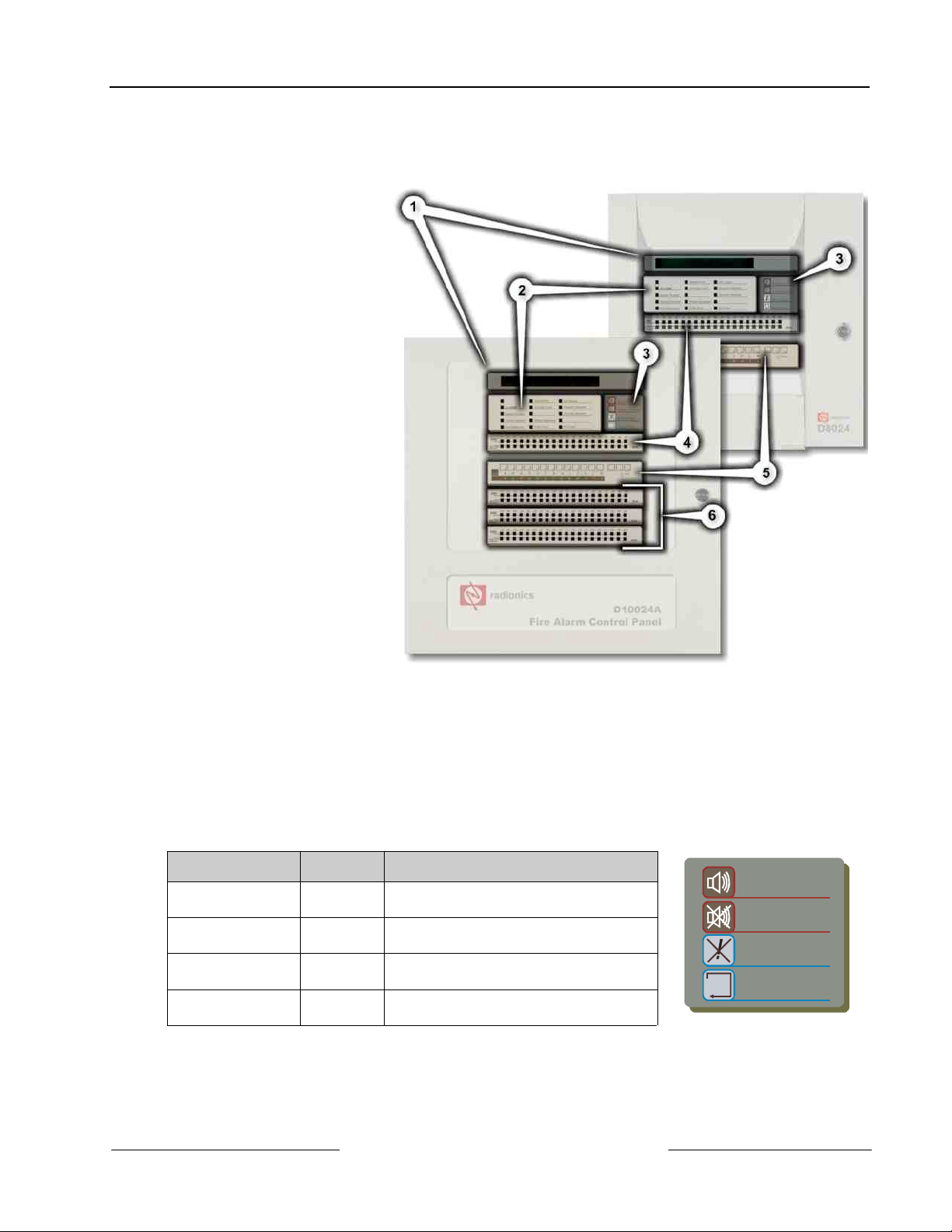
3.1 Front Panel Controls
A. LCD Display
(
See Section 3.1.5
Alphanumeric/Interactive
Control Keys on page 15
B. System Control LED
Indicators (
3.1.3 System Control LED
Indications on page 14
C. Control Keys – A bank of
four keys contains the four
system control keys: Fire
Drill, Alarm Silence,
Trouble Silence and
System Reset. (
Section 3.1.1 Control Keys
on page 13
D. Zone LED Display (
Section 3.1.4 Zone LED
Displays on page 15
E. Alphanumeric/Interactive
Control Keys - A bank of 17
keys contains interactive
and alphanumeric keys.
See Section 3.1.2
(
Alphanumeric/Interactive
Control Keys on page 14
See Section
)
See
)
See
)
D8024/D10024A
Installation
)
)
On the D8024, opening the
hinged panel gives access
these keys. This is located
below the Zone LED
Display.
The alphanumeric keys normally function as a numeric keypad. During programming, these keys can be
toggled to Letter Keys by pressing the CHANGE key. This gives access to letters A-M. For access to letters
N-Z, press and hold the SHIFT key while pressing the appropriate letter key.
F. Optional Zone LED Display (
3.1.1 Control Keys
Key Legend Purpose Function
Sound Alarms Fire Drill Press to Turn on ALL NAC Outputs (i.e.
Silence / Resound Alarm
Mute / Accept Trouble
System Reset System
Figure 1: D8024/D10024A Controls and Displays
See Section 3.1.4 Zone LED Displays on page 15
evacuate building manually).
Press to Turn off all activated NACs.
Silence
Silence
Reset
Table 4: Control Key Functions
Press again to re-activate the NACs.
Press to acknowledge events and
silence the internal buzzer.
Press to cancel all alarm conditions and
reset the panel.
)
Sound Alarms
Silence / Resound
Mute / Accept
System Reset
Figure 2: Control Keys
D8024/D10024A Operation and Installation Guide
© 2002 Radionics Page 13 50616B
D8024/D10024A
Installation
3.1.2 Alphanumeric/Interactive Control Keys
0 123456789 ><
ABCDEF GHIJKL
Shift
NOP Q RS TUVW XY
Figure 3: Alphanumeric and Interactive Control Keys
Key Legend Function
0 to 9 Press to enter numbers 0-9 or letters A-Z
> Press to scroll through fire alarms or troubles manually on the display
< Press to scroll back through fire alarms or troubles manually on the display
Change Press to change a display option (where allowed)
Enter Press to confirm entry of a multiple digit number
No Press to answer No, or terminate a display option
Yes Press to answer Yes, or step through a display option
Shift Press to show user options on the display
Press, during programming, to allow entry of Letters N-Z
Table 5: Alphanumeric and Interactive Control Keys
• The control keys are disabled at USER LEVEL 1. Pressing the SHIFT key will cause the display to prompt
for entry of the Level 2 password. The password must be entered to re-enable the control keys at Level 2.
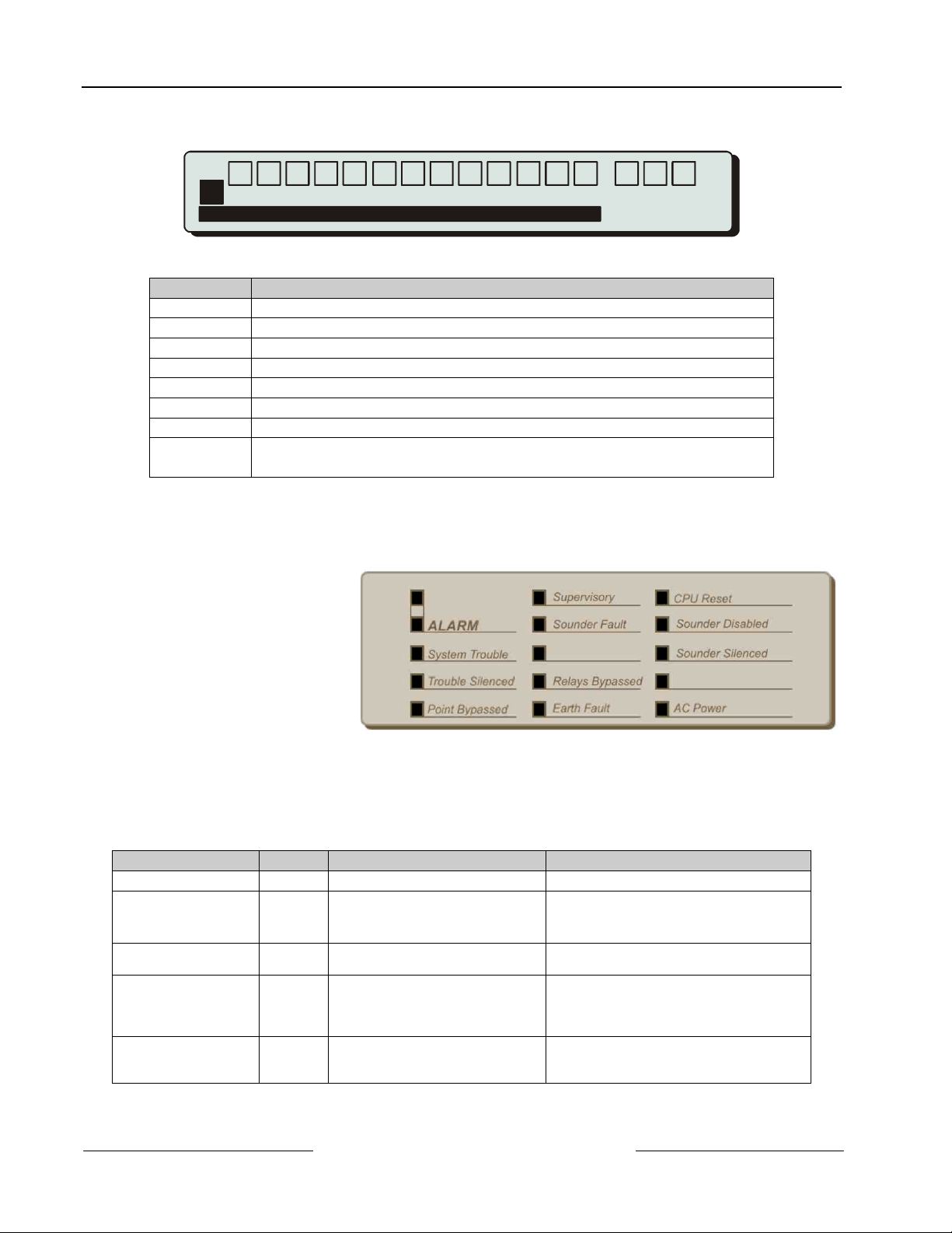
3.1.3 System Control LED Indications
• The Level 1 LED
Indicators are divided into
two sections.
• The upper array of LED
Indicators shows the
operational conditional of
the panel and the
installation.
• The lower array of Zone
LED Indicators shows the
location of a fire alarm or
trouble.
Enter
Change
M
Z
No Yes
0,9 Wor ds
A Z
Figure 4: System Control LED Display
• The standard Zone LED Indicators provide identification for up to 20 zones. On the D10024A panel, this can
be extended by adding either a further 20 zones (to give a total of 40 zones) or a further 60 zones (to give a
total of 80 zones).
• The LED Indicators illuminate as red, yellow or green to give a clear indication of the panel status as follows:
Indicator Color Function How to Clear
Blank
ALARM Red The panel has detected a fire
alarm condition, or the ‘Fire
Drill’ key has been pressed.
System Trouble
Trouble Silenced
Point Bypassed
Yellow A trouble has been detected by the
panel.
Yellow A trouble has been acknowledged
and the internal buzzer silenced.
Yellow Part of the system, either input or
output, has been disabled manually
by the user.
D8024/D10024A Operation and Installation Guide
50616B Page 14 © 2002 Radionics
Correct the condition causing the alarm
and then perform a panel reset.
Correct the condition causing the trouble and
then perform a panel reset.
Correct the condition causing alarm or
trouble and then perform a manual reset.
NOTE: If another alarm or trouble occurs, the
internal buzzer automatically resounds.
Re-enable the device or devices. The system
automatically resets.

Indicator Color Function How to Clear
Supervisory
Sounder Fault
Yellow This indicates a closed sprinkler
supervisory valve, pressure switch
or sprinkler system trouble
condition.
Yellow This indicates a wiring fault with one
of the NAC output circuits.
Blank
Relays Bypassed
Earth Fault
CPU Reset
Sounders Disabled
Sounders Silenced
Yellow The relay outputs have been
disabled.
Yellow An earth connection fault has
occurred on a cable.
Yellow The CPU has reset or a system
fault has occurred.
Yellow The NAC outputs have been
disabled.
Yellow The NAC outputs have been
silenced.
Blank
AC Power
Green STEADY: Indicates AC Power is
present. FLASHING: Indicates a
loss of AC Power or power supply
fault.
Table 6: LED Functions
3.1.4 Zone LED Displays
D8024/D10024A
Installation
Correct the supervisory condition and then
perform a panel reset.
Correct the trouble condition and then
perform a panel reset.
See Point Bypassed.
Correct the trouble condition and then
perform a panel reset.
Correct the problem, if appropriate, and then
perform a panel reset.
See Point Bypassed.
Correct the alarm condition and then perform
a panel reset. NOTE: Press ALARM
SILENCE again to reactivate the NACs. If a
new alarm occurs, the alarms will resound.
N/A
ALARM
Trouble
1 202345678910111213141516171819
Figure 5: Zone LED Display
Indicator Color Function How to Clear
ALARM
Trouble
Red FLASHING: The zone is in a fire
alarm condition.
Yellow FLASHING: The zone contains
faulty devices.
STEADY: The zone is either
disabled or in test mode.
Table 7: Zone LED Functions
3.1.5 LCD Display Indications
• The alphanumeric liquid
crystal display gives 80
characters of information on a
2-line display. The display is
illuminated to assist viewing
Figure 6: LCD Display – 80 characters on 2 lines
under dim ambient light
conditions.
• When the numeric keypad is
not in use, the display will
revert to automatically
scrolling through any fire
alarm or trouble conditions
present on the panel. If there
are no alarm or trouble
conditions, the display will
show the date and time.
Figure 7: Normal Display – Date and Time
Zone
Correct the alarm condition and then perform
a panel reset.
Correct the trouble condition and then
perform a panel reset.
Re-enable devices or cancel test mode.
D8024/D10024A Operation and Installation Guide
© 2002 Radionics Page 15 50616B
D8024/D10024A
Installation
• Pressing the SHIFT key will
show a list of optional
functions or prompt for the
level 2 password. (See
Section 3.3 Enabling Level 2
or Level 3 Access on page
16)
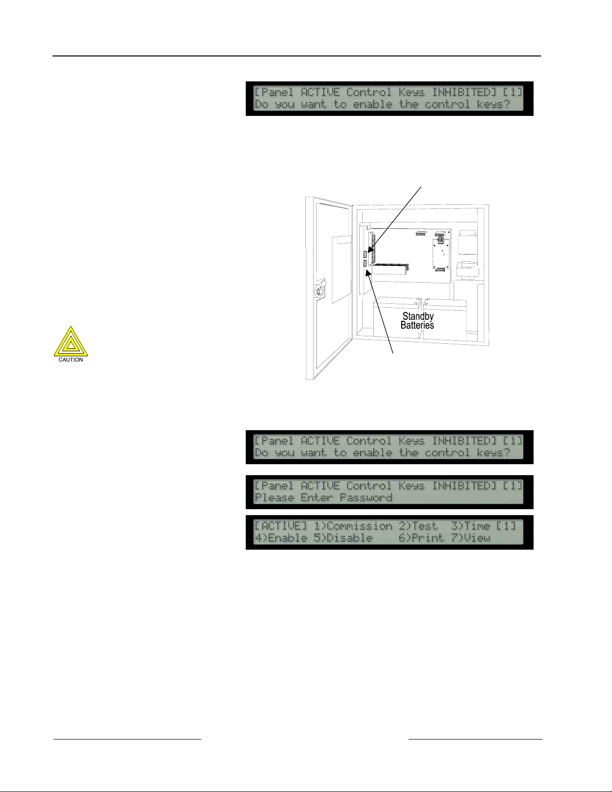
3.2 Memory Lock
• To make changes that affect the
configuration of the system, such as
adding detectors, the system memory
must first be unlocked.
• Open the enclosure door and move the
memory lock switch to the open position.
• The Memory Lock Switch is located on
the CPU Board.
• The figure opposite shows the interior of
the D8024 Fire Alarm Control Panel. The
D10024A Fire Alarm Control Panel uses
the same CPU Board and has a similar
arrangement.
Ensure that the Memory Lock Switch is
open prior to performing any
programming.
Ensure that the Memory Lock Switch is
closed before returning the panel to
normal operation.
Figure 8: Enable Control Keys?
Memory Lock Switch
Printer Port
Figure 9: Memory Lock Switch Location
3.3 Enabling Level 2 or Level 3 Access
• To enable Level 2 or Level 3
operation, press the SHIFT
key. The display will then
show:
• Press the YES key and the
display will prompt for entry of
the password.
• Enter the 4-digit Level 2
password. The display then
shows the Main Menu of user
options.
• If a key has not been pressed for a certain period, the display will revert to the normal Level 1 display
showing the system status message. To re-show the menu display, press the SHIFT key.
• If a key has not been pressed for a specified period of time, (normally 5 minutes – programmable), then
Level 2 access will be automatically canceled. It will be necessary to re-enter the password to re-activate
Level 2 functions.
• For detailed information on the Level 2 user options, refer to the
3.3.1 Selecting the commissioning option
• To access the commissioning functions in the panel, press 1 to select the commission option.
• The display will prompt for entry of the Level 3 password. Enter the Level 3 password using the number
keys and then press ENTER.
• The display will then show the commissioning menu options.
D8024/D10024A User Manual
(P/N 50618).
D8024/D10024A Operation and Installation Guide
50616B Page 16 © 2002 Radionics
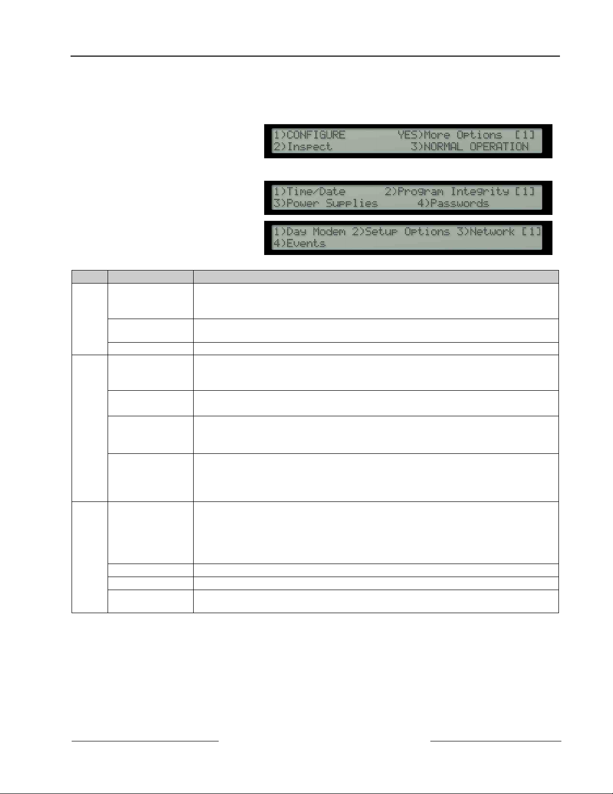
3.4 Overview of Menu Structure
• The commissioning menu options are presented in three different screens (PAGES). When the
commissioning menu option is selected, the display will show:
PAGE 1
To move between the three commissioning screens, press the YES key.
PAGE 2
PAGE 3
Page Option Function
Configure To configure the connection and operation of the signaling loop devices, peripheral
1
devices, NAC circuits and relay outputs.
Also provides configuration for upload / download of configuration data from a PC.
Inspect Provides the same functionality as the configure option but with view only. This allows
the data to be inspected without risking any inadvertent changes.
Normal Operation To return the panel to normal operation – Level 2.
Time / Date To allow the date and time and other clock functions to be changed.
2
Also allows the system memory to be cleared to return the panel back to factory default
settings.
Program Integrity To show the version of the software installed in the panel.
To show the status of the operating program and configuration memory.
Power Supplies Shows the current state of the AC and Battery supply conditions.
Note: Should the AC fail, the back lighting on the liquid crystal display will be turned
off to conserve battery power.
Passwords To define the number of User Level 2 passwords.
To define the value of each Level 2 password.
To define the maximum time the panel will remain at Level 2, without any key pressed,
before inhibiting the keys and returning to Level 1 operation.
Day Modes To define which, if any, of the following day modes are in operation.
3
Delayed Mode
Sensitivity Mode
Verification Mode
To define the effective times of operation, (i.e. start and finish).
Setup Options To define system setup parameters.
Network To define and configure the operation of the panel in a networked system.
Events To define system events that provide a more flexible cause and event function than that
available from standard zone based ringing options.
Table 8: Menu Function Overview
D8024/D10024A
Installation
D8024/D10024A Operation and Installation Guide
© 2002 Radionics Page 17 50616B
 Loading...