

Bosch D9412GV2, D7412GV2 User Manual
D9412GV2/D7412GV2
Release Notes for Version
7.09
March 2013
Table 1: Required Handlers
D5200 Handler
Version
Changes and Notes
RADXUSR1
1.06
Updated to support GV2 Series Control Panels
RADXPNTS
1.08
Updated to support GV2 Series Control Panels, version 7.05 and later
Not compatible
Not compatible
Trademarks ................................................................................................................................. 1
1.0 Requirements ................................................................................................................... 1
2.0 Firmware Revision History ............................................................................................... 3
2.1 Version 7.09 ..................................................................................................................... 3
2.2 Version 7.08 ..................................................................................................................... 3
2.3 Version 7.07 ..................................................................................................................... 4
2.4 Version 7.06 ..................................................................................................................... 6
2.5 Version 7.05 ..................................................................................................................... 7
2.6 New Features in Version 7.05 ........................................................................................... 8
2.7 Version 7.03 ................................................................................................................... 11
2.8 Version 7.02 ................................................................................................................... 12
2.9 Version 7.01 ................................................................................................................... 12
2.10 New Features in Version 7.01 ......................................................................................... 13
3.0 Known Issues ................................................................................................................. 14
4.0 Upgrading to a GV2 Series Control Panel ....................................................................... 15
Trademarks
Molex is a registered trademark of Molex Incorporated.
1.0 Requirements
GV2MAIN 1.03 New handler for the GV2 Series Control Panels, version 7.07 and later
RADXUSR2 1.05 Updated to support GV2 Series Control Panels
RADXSKED 1.04 Updated to support GV2 Series Control Panels
GV2AUX 1.03 New handler for the GV2 Series Control Panels, version 7.07 and later
RADXAXS 1.06 Updated to support GV2 Series Control Panels
9000MAIN NA
RADXAUX1 NA
with the GV2 Series Control Panels
with the GV2 Series Control Panels
D9412GV2/D7412GV2
Table 2: Supporting Literature for
D9412GV2/ D7412GV2 with
Firmware Version 7.08 and
Later
Document Name
Part Number*
B
Table 3: ROM Kit Part Numbers
Control Panel Model
Part Number
During the development of the GV2
Series Control Panels, some D5200
Handler version numbers were
skipped.
The following version numbers were
not released.
GV2MAIN v1.01
RADXUSR1 v1.05
RADXUSR2 v1.04
RADXPNTS v1.07
RADXSKED v1.03
GV2AUX v1.01
RADXAXS v1.05
Use Remote Programming Software
(RPS) version 5.7 and later with this
software version.
To acquire an update for your D5200
Programmer, call the Bosch Security
Systems, Inc. Handler Update System,
toll-free, at (800) 657-4584. Make a
separate phone call for each handler.
Use an analog telephone line with the
D5200. The D5200 dials only pulses.
Refer to Section 10 Updating Handlers
in the D5200 Programming Manual
(P/N: 74-06176-000-B) for details on
updating handlers.
D9412GV2/D7412GV2
Program Entry Guide
D9412GV2/D7412GV2
Program Record Sheet
D9412GV2/D7412GV2
Operation and Installation
Guide
D9412GV2/D7412GV2
Approved Applications
Compliance Guide
Older revisions have alphabetic revision
identifiers (for example, F01U003636
not provide information that supports version
7.05 and later firmware.
F01U003636-03
F01U003635-03
F01U003641-02
F01U003639-02
) and do
D9412GV2 R20-9412V2-ROM
D7412GV2 R20-7412V2-ROM
When upgrading from GV2 Series
Control Panel Firmware v7.03 or
older, verify all associated prompts
against the compliance table in the
D9412GV2/D7412GV2 Program Entry
Guide (P/N: F01U003636) to ensure
compliance with the ANSI SIA CP-01
False Alarm Reduction Standard.
D9412GV2/D7412GV2 Release Notes for Version 7.09
F01U003637-06 Page 2 © 201313 Bosch Security Systems, Inc.

D9412GV2/D7412GV2
2.0 Firmware Revision History
2.1 Version 7.09
The following are corrections and changes made
since Version 7.08 in the GV2 Series Control
Panels.
• Changes were made to address the missing
low battery display from wireless devices on
the Zonex Bus
2.2 Version 7.08
The following are corrections and changes made
since Version 7.07 in the GV2 Series Control
Panels.
• Changes were made to address the issues
described in the GV2 Arming Without
passcode Technical Service Note (P/N:
F01U077005).
• Changes were made to the Passcode Arm
command to support the Easy Exit feature.
Entering a passcode followed by the [ENTER]
key on a keypad showing a Ready to Arm
state will cause all authorized areas within
scope to start or restart Exit Delay.
• Changes were made to the Perimeter Partial
arm command to no longer support the Easy
Exit feature. Now, the Perimeter Partial
command (COMMAND 8) must be initiated in
a disarmed area.
• Changes were made to the function list
arming commands to support the Easy Exit
feature. The arm level can be increased from
Perimeter Armed to Master Armed. The
function list Master Delay and Perimeter
Delay arming commands do not allow the Exit
Delay to be restarted when the area is
already at the same arm level.
• Corrections were made to ensure the Local
Only reporting feature was preserved for the
following intrusion alarm events: Recent
Close Alarm, Exit Error Alarm, Cross Zone
Alarm, and Unverified Alarm. This addresses
the issues described in the SIA Panic Alarms
Technical Service Note (P/N: F01U065901).
• Changes were made to the Status Report to
allow it to send through the enhanced
communication path to the central station
receiver. The status report is not intended to
print through a D9131A printer module.
D9412GV2/D7412GV2 Release Notes for Version 7.09
F01U003637-06 Page 3 © 2013 Bosch Security Systems, Inc.
• Corrections were made to the D1260 or
D1260B Keypad to allow it to Force Arm
when arming the last associated area when a
shared area is not Ready to Arm. It is
important to note that when arming the last
associated area, that the shared area must be
within the scope of the keypad.
• Improvements were made to allow invisible
points with
Latches) to reset when the alarm memory is
cleared.
• Corrections were made the allow settings of
10 through 20 in the AC Fail Display prompt
to operate as expected.
• Corrections were made to the D720 keypad
to ensure the A, B and C keys now execute
their assigned custom functions.
• Corrections were made to the Walk Test
procedure to prevent faulted points with
Point Index set to 0 from becoming Swinger
Shunt bypassed and producing erroneous
trouble events. This addresses the issues
described in Point Index 0 Technical Service
Note (P/N: F01U089352).
• Modifications were made to the Fire Walk
Test to differentiate between fire and
intrusion points left off-normal upon the
conclusion of the test. It is an ANSI SIA CP-01
requirement that any non-controlled points
left in an off-normal state upon the
conclusion of a Walk Test be prevented from
going into immediate alarm.
• Corrections were made to ensure the All
Points Tested event is generated at the
conclusion of a Walk Test procedure when
performed on a D1260 or D1260B keypad.
• Corrections were made to ensure the Walk
Test menu returns to idle text when left idle
for no more than 20 minutes. On GV2
firmware v7.07, when left idle the Walk Test
function remained active for approximately
60 min.
• Corrections were made to the D1260 or
D1260B keypad to ensure that user Index
Authority Level assignments made through
the Add/Change User function (COMMAND
56) are propagated to the D9210B door
controllers in a timely manner.
• Modifications were made to the D1260 or
D1260B keypads to never show the
authorized areas are now arming screen
P# RlyResp Type set to 2 (Relay
P#
All user-
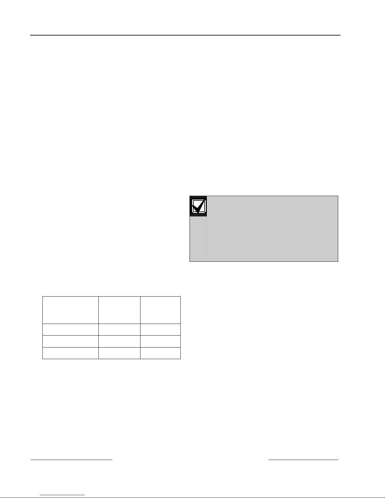
D9412GV2/D7412GV2
On-Board Relay
Relay
Number
Mapped
Relay
Number*
when performing the following arming
commands: Master Delay (COMMAND 1),
Master Instant (COMMAND 11), Perimeter
Instant (COMMAND 2), Perimeter Delay
(COMMAND 3), and Perimeter Partial
(COMMAND 8). This acknowledgement
screen is for the Passcode Arm command
only.
• Bosch Security Systems, Inc. does not
recommend setting
Yes in an area that has A# Area Type set
to
Associate or Master. Coexistence of these
to
two features is supported, but might result in
a shared area being left unintentionally
disarmed.
• Corrections were made to the RPS Callback
via Network feature in GV2 firmware V7.07
and later. This feature is best supported by
RPS v5.10 and later.
• Corrections were made to the RPS Connect
via Network (COMMAND 43) feature in GV2
firmware V7.07 and later. This feature is best
supported by RPS v5.10 and later.
• Corrections were made to ensure the Clear
Display prompt is shown on the D1260 or
D1260B keypad after an alarm is silenced by
disarming with a key-switch.
• The Change Relay function (COMMAND 54) is
modified to work with the on-board points.
Use the following relay numbers to toggle the
on-board relays:
A (terminal 6) 253 250
B (terminal 7) 254 251
C (terminal 8) 255 252
*Remote systems identify the on-board
relays by different numbers, so those values
automatically map to the local values.
• Improvements were made to the Secure Door
and Unlock Door commands to show current
door status in a more consistent manner.
Previously, the Secure Door or Unlock Door
status was momentarily defaulting to the
door number on the keypad display.
D9412GV2/D7412GV2 Release Notes for Version 7.09
F01U003637-06 Page 4 © 201313 Bosch Security Systems, Inc.
A# Master Arm – No Exit
2.3 Version 7.07
The following corrections and changes were
made in the GV2 Series Control Panels since
Firmware 7.06:
• The RPS port number prompt was renamed
and moved from
SDIRPS/ENHANCED CONF →
BasePortNumber to GV2AUX → SDI RPS
PARAMETERS → RPS Port Number in
GV2AUX v1.03.
• The Anti-Replay enable prompt for the Anti-
Substitution feature was renamed and moved
GV2AUX → MISCELLANEOUS →
from
EnableAntireplay to GV2AUX → ENHANCED
COMM → Path #AntiReplay in GV2AUX
v1.03. The value in the
prompt when using GV2AUX v1.02 or older
shows in the
When you upgrade a D9412GV2 or
D7412GV2 with firmware version 7.07
or later, you must enable the AntiReplay option individually for each
enhanced communication path if you
are using this feature. Previously, one
prompt applied to all destination
paths.
• Changes made improve the reliability of the
Time Sync feature. When enabled, this
feature no longer causes intermittent
erroneous skipping or duplication of skeds.
This corrects the issues described in the G-
GV2 Series Skeds Technical Bulletin (P/N: TBI
10-5-06 1 B).
• For optimal keypad user interface
performance, ensure that any D1260 or
D1260B Keypads connected to the system
are running firmware version 1.04 or later. An
update kit (P/N: R19-D1260-0104) is available
from Customer Service: (800) 289-0096.
• Changes made prevent the recent close alarm
feature from interfering with panic alarm
reports. Now, a panic alarm (an alarm
generated by a 24-hour point) is reported as
a Burglar Alarm in any arming state. This
corrects the issue described in the SIA CP-01
and Panic Alarms Technical Bulletin (P/N:
F01U064901-01).
• Changes made prevent corrupted account
codes for systems that communicate with BIS
2.0 Security Engine. These changes are only
GV2AUX→
EnableAntireplay
Path 1 Anti-Replay
prompt.

compatible with BIS Security Engine
v2.1.1271 or later. This addresses the issues
described in the BIS SEE and GV2/G Series
Technical Service Note (P/N: F01U073249).
• Changes made allow the Relay Latches on
point fault option for the
Type
feature to reset when a passcode is
entered even when the associated point has
not returned to normal. This correction does
not apply to invisible points.
• Corrections made to the View Points menu in
the D1260 and D1260B user interface now
allow the display to advance even when there
is only one viewable point in the area. This
addresses the issue described in the
Unresponsive D1260 Keypad Technical Bulletin
(P/N: TBI 02-09-07 01).
• Corrections made to the Door Control
(COMMAND 46) menu and its associated submenus now enforce the door’s area
assignment and the user authority level
assignments for the following permissions:
L# Unlock Door, L# Cycle Door
Secure Door
• Corrections made now allow the use of any
enhanced communication path in any route
group. For example, Enhanced
Communication Path 2 can be the primary
destination for Route Group 4 with Phone
Number 3 as backup. However, the primary
and backup paths for any route group must
be different.
• Changes made now allow the clearing of the
alarm memory when there are only non-fire
points faulted. However, the UL required
prevention of alarm memory erasure while
there are fire points faulted is still enforced.
If an area has faulted fire and non-fire points,
then the alarm memory is locked until the fire
points are returned to normal.
• Changes made to the enhanced
communication path acknowledgement wait
time do not allow the no-ack-required option
when anti-replay is enabled for the same
path. When
Path # ACK Wait Time
and
the zero value is treated as if it were the
minimum setting of 5 seconds by the control
panel.
.
Path # Anti-Replay
P## Relay Response
, and
L#
is set to Yes
with is set to 0,
D9412GV2/D7412GV2
• Changes made allow the Manual Idle Text
Forward Scroll to show faulted points when
you set
condition occurs.
• Changes made allow the View Area Status
display on the D1260 and D1260B Keypads to
show the default Area Arm Status text.
• Changes made to the View Log menu on the
D1260 and D1260B Keypads now show the
second line of event information.
• Changes prohibit using a walk test command
when the control panel is in Power-up
Standby mode. During the Power-up Standby
mode, all points on the control panel are
initializing and considered to be in the offnormal state. The system ignores any state
transitions until the Power-up Standby
window expires. Because of required SIA CP01 enhancements to the Fire Walk Test
command initiated in v7.05, any 24-hour or
fire point that remains off-normal when you
exit from the test is automatically bypassed
regardless of the point’s configuration. In the
GV2 control panels, any bypassed noncontrolled point (fire or 24-hour) can be
returned to service only by individually
unbypassing each point using CMD 00. These
changes address the issues described in the
GV2 Fire Walk Test Technical Bulletin (P/N: TBI
09-27-07 01).
• Changes made to the Trouble LED on the
D1255RB and D1256RB Fire Keypads, and
D1257RB Fire Annunciator, now indicate
when the control panel is in Power-Up
Standby mode.
• Changes made improve the accuracy of the
Low Battery Monitor.
2.3.1 New Features in Version 7.07
• Enhanced Communication Path Port
Numbers: A new prompt was added to each
of the four enhanced communication paths
Path # Port Num) to specify an individual
(
destination port number. All four IP/port
pairs must be unique to ensure event
acknowledgements are accounted for
correctly. Duplicate IP address/port pairs can
cause unreliable communication. This
enhancement further facilitates the Port
Address Translation feature added in V7.06.
When upgrading from V7.06 or later, these
CC# Scroll Lock
to Yes and an alarm
D9412GV2/D7412GV2 Release Notes for Version 7.09
© 2013 Bosch Security Systems, Inc. Page 5 F01U003637-06
 Loading...