

Bosch AMAX 2100, AMAX 3000 BE, AMAX 3000, AMAX 4000 Quick Start Manual
AMAX panel
AMAX panel 2100 | AMAX panel 3000 | AMAX panel 3000 BE | AMAX panel 4000
en Quick Start Manual


Table of contents
1
Safety 4
2
Short information 6
3
System overview 7
4
Connecting Modules and Devices 10
5
Programming and Operating the AMAX System 11
5.1 Option: Changing Menu Language 11
5.2 Accessing the Menus 11
5.3 Menu Navigation 11
5.4 Programming the AMAX System via Keypad 12
5.4.1 Setting Date and Time 12
5.4.2 Deleting a Zone 12
5.4.3 Enabling the RF Receiver for Wireless Communication 13
5.4.4 Setting up a Zone for an RF Device 13
5.5 Programming the AMAX Sytem via PC and USB 14
5.5.1 Installing the Programming Software 14
5.5.2 Connecting the PC and the AMAX Panel 14
5.5.3 Starting the Programming Software 14
5.5.4 Setting the COM Port 15
5.5.5 Option: Creating a New Customer 17
5.5.6 Configuring the Control Panel 18
5.5.7 Establishing a Direct Connection 21
5.6 Menu Programming 22
6
Technical Data 32
AMAX panel Table of Contents | en 3
Bosch Sicherheitssysteme GmbH Quick Start Manual 2015.05 | 05 | F.01U.309.297
Safety
Danger!
Electricity
Injuries due to electricity are possible if the system is not operated correctly or if the system
is opened or modified not accordingly to this manual.
– Disconnect all Telecommunication Network Connectors before switching off the power.
– To switch off the power, make sure to have a circuit breaker available.
– Make sure that the system is switched off during the installation and wiring process.
– Only open or modify the system accordingly to this manual.
– Make sure to connect the system to a socket-outlet with a protective grounding contact.
– Only qualified installers /service personnel are allowed to install this system.
Danger!
Battery
Injuries due to electric shock, fire or explosion are possible if the battery is handled or
connected incorrectly.
– Always handle the battery carefully and replace it carefully.
– Make sure that the grounding terminal is always connected and that N, L1 or xx are
connected correctly.
– Make sure to first disconnect the positive wire of the battery when removing it from the
system.
– Be careful when connecting the positive (red) wire and the "BATT +" port of the system.
Make sure not to short-circuit with the "BATT +" port of the AMAX panel or the housing to
prevent electric arc from occurring.
Danger!
Electrostatic-sensitive components
Injuries due to electric shock are possible if anti-static steps are not followed.
– Always contact the grounding terminal before installing the system to discharge the
possibly carried static electricity.
!
Caution!
Sensitive components
Damage of sensitive components is possible if the system is not handled carefully or if the
system is opened or modified not accordingly to this manual.
– Always handle the system carefully.
– Only open or modify the system accordingly to this manual.
!
Caution!
Battery
Damage or contamination of the system is possible if the battery is not handled correctly or if
the battery is not replaced on a regular basis.
– Only use a non-spillable battery.
– Place a label with the last replacement date on the battery.
1
4 en | Safety AMAX panel
2015.05 | 05 | F.01U.309.297 Quick Start Manual Bosch Sicherheitssysteme GmbH
– Under normal conditions of use, replace the battery every 3-5 years.
– Recycle the battery after replacement according to local regulations.
!
Caution!
Installation
Damage or malfunction of the system is possible if the system is not mounted and installed
correctly.
– Place the system inside the monitored area on a stable surface.
– Make sure to mount keypads on the inner side of the monitored area.
– Once the system is tested and ready to use, secure the enclosure door and additional
enclosures with screws.
!
Caution!
Maintenance
Damage or malfunction of the system is possible if it is not maintained on a regular basis.
– It is recommended to test the system once a week.
– Make sure to get the system maintained four times a year.
– Only qualified installers /service personnel are allowed to maintain this system.
AMAX panel Safety | en 5
Bosch Sicherheitssysteme GmbH Quick Start Manual 2015.05 | 05 | F.01U.309.297

Short information
This Quick Start Guide contains information on how to get the system into operation easily
and quickly. The guide describes the main steps required for basic system installation and
setup of an AMAX panel together with one IUI-AMAX4-TEXT keypad and one RFRC-OPT
RADION receiver. The program tree structure is provided at the end of this guide.
Detailed information about installation of other modules and devices, advanced settings and
programming can be found in the Installation Guide. For detailed operation information,
please refer to the User Guide.
2
6 en | Short information AMAX panel
2015.05 | 05 | F.01U.309.297 Quick Start Manual Bosch Sicherheitssysteme GmbH
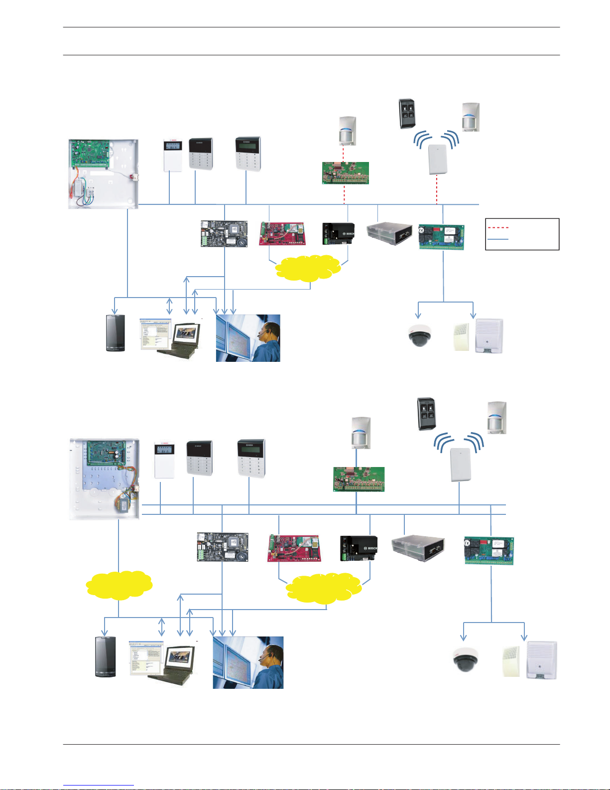
System overview
DX2010
Option Bus
B426
A-Link Plus
CMS
Ethernet
Video
DX4020G
PSTN
GSM/
GPRS
AMAX 3000
AMAX 2100 / 3000
Radion
DX3010
Text KeypadLCD / LED Keypad
DX4010V2
B450
(B442/B443)
GPRS
Figure 3.1: AMAX 2100 / 3000 Overview
DX2010
Option Bus
B426
A-Link Plus
CMS
Video
PSTN
Radion
DX3010
Text KeypadLCD / LED Keypad
DX4020G
GSM/
GPRS
DX4010V2
B450
(B442/B443)
GPRS
Ethernet
Figure 3.2: AMAX 3000 BE / 4000 Overview
3
AMAX panel System overview | en 7
Bosch Sicherheitssysteme GmbH Quick Start Manual 2015.05 | 05 | F.01U.309.297
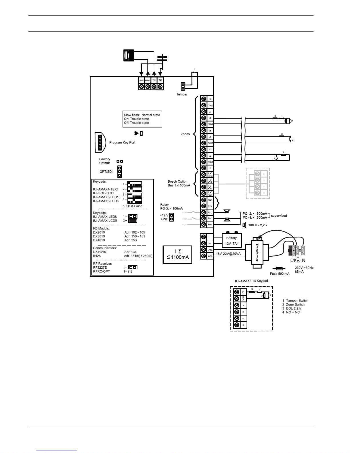
Wiring diagrams
/ B450
≤ 500mA
Figure 3.3: Wiring diagram AMAX 2100 / 3000
8 en | System overview AMAX panel
2015.05 | 05 | F.01U.309.297 Quick Start Manual Bosch Sicherheitssysteme GmbH
Program Key Port
GND
-
+
AC
AC
Transformer
Battery
Tamper
L2 COM
COM
COM
L1a
L3
L4
L5
L6
L7
L8
L9
COM
COM
COM
COM
L10
L11
L12
L13
L14
L15
L16
P0+4
R
B
G
Y
AUX1
-
AUX2
-
AUX1
+12V
Y
G
B
R
RINGRHTHTIP
L1b
P0+3
P0+
P0-2
P0-1
Z
ones
B
o
s
ch Op
t
i
on
B
u
s
2 < 900mA
+
1
2V
+
0 V
1
2
3
3
1 Tamper Switch
2 Zone Switch
3 EOL 2,2 k
4 NO + NC
3
2
3
2
Fuse 1 A
PO+4: < 750mA
PO+3: < 750mA
PO -2: < 500mA
PO -1: < 500mA
230V ~50Hz
230mA
Wachdog
output
<
1
00m
A
12V < 18Ah
18VAC@50VA
Zones
AUX 1: < 900mA
AUX 2: < 900mA
A
UX Power
Fire
I
ntrusion
3
3
2
Slow flash: Normal state
On: Trouble state
Off: Trouble state
_
_
_
_
_
_
_
_
+12V
+12V
+12V
COM
_
12V 7Ah
AUX2
+12V
_
COM
s
u
pervised
PO-5
Z1
2
2
3
3
Keypads:
IUI-AMAX4-TEXT
IUI-SOL-TEXT
IUI-AMAX3-LED16
IUI-AMAX3-LED8
Keypads:
IUI-AMAX-LED8
IUI-AMAX-LCD8
I/O Moduls:
DX2010 Adr. 103 - 108
DX3010 Adr. 150 - 151
DX4010 Adr. 253
Communicators:
DX4020G Adr. 134
B426 / B450 Adr. 134(6) / 250(9)
RF Receiver:
RF3227E 1=
RFRC-OPT 1= (1)
1 =
2 =
3 =
4 =
1 =
2 =
B
o
s
ch Op
t
i
on
B
u
s
1 < 900mA
C
OM
R
B
G
Y
R
B
G
Y
R
B
G
Y
♥
IUI-AMAX3
+
4 Keypad
3
1
2
1
Factory
Default
5-16 Inst. Guide
I
2
000mA
100 Ω - 2,2 k
_
<
∑
3
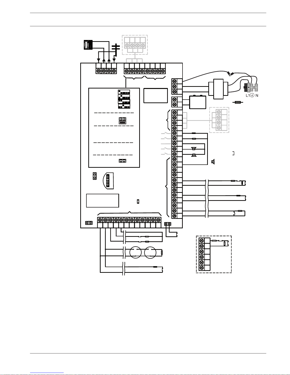
Figure 3.4: Wiring diagram AMAX 3000 BE / 4000
AMAX panel
System overview | en 9
Bosch Sicherheitssysteme GmbH Quick Start Manual 2015.05 | 05 | F.01U.309.297
Connecting Modules and Devices
The AMAX panel provides BOSCH option bus 1 and option bus 2 (only for AMAX 3000 BE and
AMAX 4000) to connect modules and devices. Each module can be connected to each bus.
A maximum of 14 modules (8 keypads) can be connected to each bus.
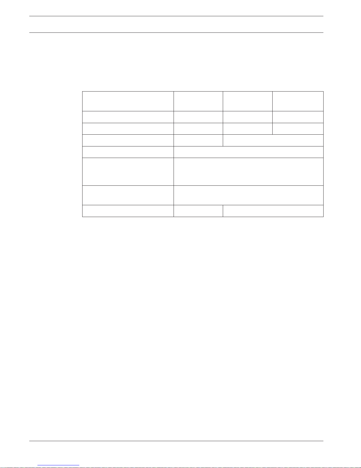
The following overview displays the maximum number of modules that can be connected.
Module AMAX 2100 AMAX 3000 /
3000 BE
AMAX 4000
Keypads 4 8 16
DX2010 - 3 6
DX3010 1 2
DX4010 1
GPRS module:
B450 with B442 or B443, DX4020G
Up to 2 different GPRS modules, each GPRS module can
only be connected once. Exception: 2 B450 modules can
be connected.
IP module:
B426
2 (1 if one of the GPRS modules above is connected, 0 if
two of the GPRS modules above are connected)
RF receiver - 1
Table 4.1: Maximum number of modules
How to connect a keypad and a RADION receiver:
1. Connect the keypad to the option bus on the AMAX panel according to the wiring diagram
(refer to Graphics).
2. Connect the RFRC-OPT RADION receiver to the option bus on the AMAX panel according
to the wiring diagram (refer to Graphics).
3. Connect the red and black wires supplied with the battery to the AMAX panel and the
battery.
4. Connect the power adapter and battery to the mains.
4
10 en | Connecting Modules and Devices AMAX panel
2015.05 | 05 | F.01U.309.297 Quick Start Manual Bosch Sicherheitssysteme GmbH

Programming and Operating the AMAX System
The AMAX system can be programmed and operated with menus by using keypads and/or the
A-Link Plus remote programming software on a PC.
When all modules and devices are installed, the AMAX panel indicates the system status with
the LED status indicator on the system main board. A slow flashing in red (repeating on and
off with an interval of 1 second) indicates normal system operation.
The AMAX panel begins charging the battery. The green MAINS indicator on the keypad
indicates that the power supply is switched on and the keypad beeps.
4 Press any key on the keypad.
The keypad stops beeping and you are prompted to enter a code.
The AMAX system provides two types of default access codes:
– Installer Code: [1234]
– User Code: [2580] for master user 1 / [2581] for master user 2
Option: Changing Menu Language
If necessary, the menu language can be changed. If not, proceed to section Accessing the
Menus, page 11.
1. Enter the installer code [1234] + [58] or the user code [2580] / [2581] + [58] and press
[#].
The available menu languages are displayed.
2. Select the desired language on the keypad.
3. Press [#].
P The menu language is changed.
Accessing the Menus
Accessing the Programming Menu
1. Confirm that the system is disarmed.
2. Enter the installer code. The default setting for the installer code is [1234].
The system displays [958] PROGR. MODE [-EXIT].
3. Enter [958] + press [#].
P You have now access to the programming menu for configuring the AMAX system.
P The STAY and AWAY indicators flash to indicate the programming mode.
Accessing the User Menu
4 Enter a user code. The default users are master user 1 (code: [2580]) and master user 2
(code: [2581]).
P The system displays [▼/▲] USER MENU *STAY #AWAY [-] INFO.
P You have now access to the user menu for operating the AMAX system.
Menu Navigation
This section provides an overview of how to navigate the programming menu of a text keypad.
Selecting a Menu
1. Select the menu and operate according to the menu prompt.
2. Press [▼] or [▲] to navigate to the desired menu.
3. Press [#] to enter a menu.
5
5.1
5.2
5.3
AMAX panel Programming and Operating the AMAX System | en 11
Bosch Sicherheitssysteme GmbH Quick Start Manual 2015.05 | 05 | F.01U.309.297

Exiting a Menu
4 Press [–] to get back to the previous menu.
Confirming the Input
4 Press [#] to confirm the input.
Switching between Settings
4 Press and hold [*] for 3 seconds to switch between settings.
Operating a Menu
1. Operate according to the menu prompt.
Select the menu and enter data for specific programming items according to the display
on the keypad to complete the programming, step by step.
2. Press [#] to confirm each step.
Exiting the Programming Menu
1. Complete all programming input by repeating the programming steps above and press [–]
to get back to the current main menu level by level.
2. Press [–] to get to the EXIT PROG. +SAVE menu.
It is optional to save or not to save the programming data.
1. Select EXIT PROG. +SAVE and press [#] to save the data and to exit the programming
mode.
2. Select EXIT PROG. UNSAVED and press [#] to exit programming mode without saving
the data.
Programming the AMAX System via Keypad
If the keypad is in standby mode, it gets enabled as soon as the first digit of a code is entered.
Setting Date and Time
After the system is powered up, date and time must be set. Otherwise, the system displays a
fault.
1. Make sure that the system is in a disarmed status (the STAY and AWAY indicators are
disabled).
2. Enter the installer code [1234] + [51] and press [*] to get to CHANGE DATE / TIME.
3. Enter the current date and time by using the numeric keys and press [*] to confirm.
P Date and time are set.
Deleting a Zone
The zones 1-8 are enabled by default. The zone type for zone 1 is set as 03-delay 1, for zones
2-8 as 01-instant by default. Perform the following steps if you want to delete a zone.
1. Enter the installer code [1234] + [958] and press [#].
2. Select 3 ZONE MANAGER and press [#].
3. Select ADD/DELETE ZONES and press [#].
The system displays the next menu item: INPUT ZONE No.
4. Enter the number of the zone you want to delete (example: 1) and press [#].
The system displays the next menu item: ZONE MODULE SEL.
5. Select the correct zone module (default is 0-on board zone) and press [#].
The system displays the next menu item: ZONE FUNCTION.
6. Enter 00 for the zone function 00-not used and press [#].
The system displays the next menu item: ZONE IN AREA. There is no need to proceed to
the following menu items for deleting a zone.
5.4
5.4.1
5.4.2
12 en | Programming and Operating the AMAX System AMAX panel
2015.05 | 05 | F.01U.309.297 Quick Start Manual Bosch Sicherheitssysteme GmbH
 Loading...