

Block PVUC 24/24-10, pvuc 24/24-10D, PVUC 24/24-20 User guide [ml]
Sicherheitsmaßnahmen vor der Installation
Das Betriebsmitt el ist vor unzulässiger Beanspruchung zu schüt zen.
Insbesondere dürfe n bei Transport und Handhabung keine Bauelemente verboge n und/oder Isolationsabs tände verändert werde n. Die
Berüh rung elek tri scher Bau eleme nte und Kont akt e ist zu vermeide n.
Betr iebsm itt el immer im spannun gsfr eien Zustand mont ieren und
verdr ahten. Die Produktbeschr eibung und die technis chen Hinweise in
unser em Hauptkatal og sowie die Aufs chri ft en am Betriebsmit tel und
auf dem Typenschild sind zu beacht en.
Installation
Die Installati on ist entspr eche nd den örtlic hen Gegeb enheiten , einschlägigen Vorschrifte n (z. B. VDE 0100), nationalen Unf allverhüt ungsvorschri ft en (z. B. UVV-V BG4 bzw. BGV A2) und den anerkannt en Regel n
der Technik durch zuführen . Dieses elek tri sche Bet rieb smit tel ist eine
Komponent e, die zum Einbau in elekt risc he Anlagen oder Maschinen
bestimmt ist und erfü llt die Anfo rder ungen der Nied erspannung sricht linie (73/23/E WG) . Bei Einbau in Maschinen ist die Aufnahm e des
bestimmung sgemäßen Betr iebes solange untersag t, bis fest gest ellt
wurde, dass die Maschine den Bestimm ungen der Masc hinen richtlini e
(89/392/E WG) ents pricht; EN 60204 ist zu beacht en. Die Aufnahme
des bestimmungsgemäßen Betriebes ist nur bei Einhaltun g der EMVRicht linie (89/336/EWG) erl aubt . Die Einhaltung der durch die EMVGeset zgebung gefo rder ten Gre nzwert e liegt in der Verantw ort ung des
Herstellers der Anlage oder Maschine.
Installation
Anschluss
PVUC
BLOCK Transformatoren-Elektronik GmbH & Co. KG
Max-Planck-Straße 36–46
27283 Verden
Germany
Phone +49 4231 678-0
Fax +49 4231 678-177
info@block-trafo.de
www.block-trafo.de
www.pv400.de
Technische Änderungen vorbehalten.
Subject to change.
KAPVUC 06.08.PDF.0 Printed in Germany
Kapazitives Puffermodul
Capacitive buffer module
1
2
3
LEDs: Die grün e LED (a) leucht et, wenn Uout > ca. 20 V ist. Die
gelbe LED (b) leuc hte t, wenn die inte rnen Kapa zitäten geladen
werde n. Die rote LED (c) leuchte t, wenn Uout < ca. 20 V.
Ausga ng OUT
Einga ng IN/SIG NAL
Zusch alts chwel le einst ellen (z wischen 20,4 bis 24 Vdc
einst ellbar)
pote nzial frei er Meldea usga ng (Kontakte 1 und 4 geschlossen,
bei Eingangsspan nung > 22 Vdc und gelade nen Kapazitä ten)
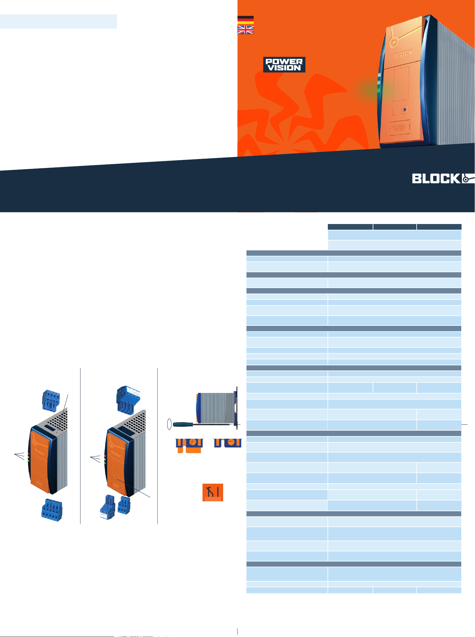
Mont age: PVUC mit geö ffnete r Schließ nocke (5a ) im rechten
Winkel auf die Tragschiene TS35 setze n. Befe stigung mit Schrau bendr eher im Uhrzeigersinn schließen( 5b).
Downl oad der ausfü hrlic hen Betriebs anlei tung unt er: www.pv400.de
Downl oad the compl ete user manual at www.pv400.d e
5
TH35
6
a b
ü
ü
7
www.pv400.de
KAPVUC 2008•06
block-trafo.de
Connection
Safety measures before installation
This equipment is to be protected against improper use. Comp onents
are not to be bent or isolation spacing chan ged, espe ciall y throug h
handling and transpo rt. The contac t with elec tric al compon ents and
terminals is to be avoided. Always disc onnect the equipm ent from the
mains suppl y, befor e commenc ing installat ion or wiring . The produc t
descr ipti on, technical informa tion in our main catalogue and the marking on the equipm ent rati ngs plate are to be observed.
Installation
Installat ion must be carried out according to the prevailing local
condi tions and safety reg ulations (e.g . VDE 0100) national accide nt
prevention regulations (e.g. UVV-VBG4 or BGV A2) and the gener ally
accepted rules of technology. This equ ipmen t is a compo nent desi gned
for installat ion into electrical syst ems and machin es, and fulf ils the require ment s of the low voltage guid elines (73/23/ EWG). When installed
into machinery, the normal opera tion is forbidden unt il it is determined
that the machi ne fulfils the requi rements of the machin ery guide lines
(89/392/E WG). EN 60204 must be obser ved. The EMC require ment s
must be fulfi lled bef ore oper atio n is commence d. The obser vance of the
requi red limitations for the EMC legislatio n is the responsibilit y of the
manufactu rer of the installat ion or machine ry.
Installation
T
To reduce the risk of mista king the term inals , the supplie d
termi nals must be used .
T
Um Verwech slung en mit andere n Anschl üsse n zu vermeide n, verwen den Sie aussc hließ lich die mit gelie fer ten
Stec ker.
4
1
2
3
LEDs: The gre en LED (a) light s when Uout >approx. 20 V. The yellow LED (b) light s when the inter nal capacitor s are being charg ed.
The red LED (c) light s when Uout <approx. 20 V.
Outp ut OUT
Input IN/ SIGN AL
Sett ing the swit ch-i n thresho ld (can be set betwe en 20.4 and
24 VDC)
Floa ting sign allin g output (co ntac ts 1 and 4 closed, at input voltage > 22 V DC and charged capac itor s)
Mount ing: Plac e the PVUC with opened cam lock (5a) in a 90°
angle on the DIN 35 mm rail and close the cam lock in a clock wise
direc tion with a screwdriver (5b).
7
6
1
a
b
c
2
4
Meldeausgang
2 1 4
PVUC 24/2 4-10 PVUC 24/2 4-10 D PVUC 24/24- 20
Puff ermo dul auf Konde nsat orbas is für TH35-Schie nenmontage
oder Schraubbesfes tigung
Capac itiv e buffe r module for mount ing on DIN 35 mm rails
or screw mounting
Norme n Safet y stand ards
Sicherheit Safety EN 60950, UL 60950, UL 508 EN 60950, UL 60950, UL 508
EMV
EMC
EN 61000-6 -2 und EN 61000-6-3 (Fachg rundn ormen)
EN 61000-6 -2 and EN 61000-6-3 (gener ic standard)
Zulas sunge n Approvals
UL (vorber eit et)
UL (Pending)
UL 60950 / UL 508
UL 60950 / UL 508
Umwel t Environme nt
Umgebu ngst emperatur Ambient temperature –10° C bis +60° C –10° C to +60° C
Lager temperatur Storage tempera ture –25° C bis +85° C –25° C to +85° C
Kühlar t
Cooling
Selbs tkühlung durch natürliche Konve ktion bei vertikaler Einb aulage
AN (Natur al air convec tion cooling )
Zulässige Luftfeuchtigkeit
Allow able humid ity
30 bis 85% relativ e Feucht e, keine Bet auung zulässig
30 to 85% relativ e humidit y with no dew
Siche rheit und Sch utz Safet y and protec tion
Prüf spannung HV test voltag e 500 Vdc (Klemme n zum Gehäuse) 500 Vdc (clamps to case)
Bauar t
Const ruction
gekapselt , für den Einbau im Schalt schrank
enclo sed for installat ion in switc hing cabi nets
Schut zar t Protection inde x IP 20 (nach EN 60529) IP 20 (to EN 60529)
Schut zkl asse Safet y class III III
Verpol schutz Reverse connect ion prot ect ion ja yes
Einga ng Inpu t
Eingan gsnennspann ung Designat ed input voltage 24 Vdc 24 Vdc
Bereich Voltage range 20 bis 30 Vdc 20 to 30 Vdc
Puf ferzeit
Puf fer time
0,6 Sek. (20, 4 Vdc / 10 A)
0,6 Sek. (20, 4 Vdc / 10 A)
2,0 Sek. (20, 4 Vdc / 10 A)
2,0 Sek. (20, 4 Vdc / 10 A)
0,55 Sek. (20,4 Vdc / 20 A)
0,55 Sek. (20,4 Vdc / 20 A)
Ladez eit Charging time typ. 7 Minuten typ. 7minutes
Zuscha ltschwel le (einstellbar)
Threshold level (adjustable)
20 bis 24 Vdc
20 to 24 Vdc
Stro mauf nahme (Bereit scha ft /Lad evor gang/max)
Input curr ent (st andby/charging process/max .)
60 mA / 1 A / 11 A
60 mA / 1 A / 11 A
60 mA / 1 A / 22 A
60 mA / 1 A / 22 A
Ansch lüsse: WAGO Multiste ckersyst em
Terminals: WAGO multi plug system
Serie 231 max 2,5 mm²
serie s 231 max. 2,5 mm²
Serie 831 max. 10 mm²
serie s 231 max. 10 mm²
Ausga ng Outp ut
Ausgangsnennspann ung Designated output volt age 24 Vdc 24 Vdc
Ausgangsspannung (Nennbet rieb)
Outpu t voltage (normal ope rati on)
U
in - 0,5 Vdc
U
in - 0,5 Vdc
Ausgangsspannung (Puffe rbet rieb )
Outpu t voltage (puffer opera tion )
20,4 bis 24 Vdc (einstell bar)
20,4 to 24 Vdc (adjustable)
Ausgangsstrom
Outpu t curren t
10 A
10 A
20 A
20 A
Übers tromschu tz (Puf ferbet rieb)
Over curr ent protection (pu ffe r operat ion)
elektron isch, typ. 11 Adc
electronic, typ. 11 Adc
elektron isch, typ. 22 Adc
electronic, typ. 22 Adc
Parallelsc haltbarkeit Parallel oper ation ja yes
Verlus tleistung
Power los ses
1,5 W / 6,5 W
1,5 W / 6,5 W
1,5 W / 15 W
1,5 W / 15 W
Ansch lüsse: WAGO Multiste ckersyst em
Terminals: WAGO multi plug system
Serie 231 max 2,5 mm²
serie s 231 max. 2,5 mm²
Serie 831 max. 10 mm²
serie s 231 max. 10 mm²
Signa lisie rung Signal ling
Power Goo d am Ausgang (DC OK), LED
Power Goo d at output (DC OK), LED
Uout > ca. 22 Vdc: LED grün leuchtet , LED rot aus
Uout > approx. 22 V D C: Green LED lights up, red LED goes out
DC OK und Kapazitäten gela den, pot enzi alfr eier
Kontakt
DC OK and capacitors charg ed, floa ting contact
Relais kont ak, Typ: Wechsler, Schaltle istu ng: 30 Vdc / 1 A (240 Vac / 0,5 A)
Relay contact , type: Changeove r contact, swi tchi ng capaci ty: 30 V DC/1 A
(240 V AC/0.5 A)
Laden der int ernen Kapazit äte n, LED
Chargi ng of intern al capaci tors, LED
Laden: LED gelb leuchte t
Chargi ng: Yellow LED light s up
Ansch lüsse: WAGO Multiste ckersyst em
Terminals: WAGO multi plug system
Serie 231 max 2,5 mm²
serie s 231 max. 2,5 mm²
Sons tiges Variou s
Maße B x H x T (ohne Anschlussstec ker)
Dimensions width x height x depth
(Wi thou t connec ting plug )
57 x 127 x 179 mm
57 x 127 x 179 mm
Gewic ht Weight 1,0 kg 1,0 kg
Best ellnu mmer Order no. PVUC 24/24-10 PVUC 24/24-10D PVUC 24/24- 20
Technische Daten
Technical details
5
4
7
6
Abbildung zeigt den P VUC 24/24-10
This figure shows the PVUC 24/24-10
Abbildung zeigt den P VUC 24/24-20
This figure shows the PVUC 24/24-10
3
5
2
4
1
a
b
c
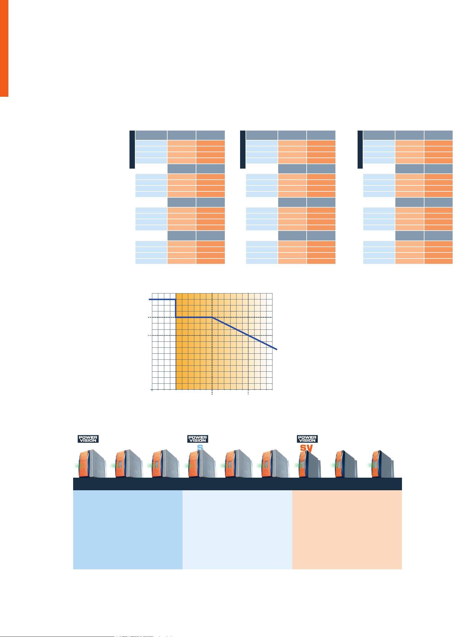
Ausgangsspannungskarakteristik
Output voltage characteristic
U1 Eingangsspannung = Ausgang sspannung + 0,5 V
U2 Einge stellte Ausg angsspannun g bei Pufferbetrieb (U2<U1)
U3 Ausgangsspa nnung (19,2 V) bei t2
t0 einset zend er Pufferbetri eb bei Ausfal l von U1
U1 Input vol tage = Outpu t voltag e + 0,5 V
U2 Outp ut voltage setting in buffer operat ion (U2<U1 )
U3 Outp ut volta ge (19,2 V) at t2
t0 Buff er operationa l when U1 is not present
Funktionen und Anwendungsbereiche
PVUC ist ein Puf fer modul für kur zzei tige Net zunterbrechungen
auf Kondensatorbasis. Bei einem Absinken der Einga ngsspannung
unterhalb der eingeste llten Zuschal tschwell e, wird die benötigt e
Energ ie für die angesch lossenen Verbraucher durch die inter nen
Kapazitäten zur Verfü gung gest ellt .
Die Zusch alts chwel le kann nach Aufl adung der Kap azit äten im
Leerl auf und ohne Verso rgun gsspa nnung mi t einem Schrau bendr eher eing este llt werde n. Für das Einste llen der Zuschalt-
schwe lle muss am Ausgang des Gerä tes ein Spann ungsmessgerät
zur Kontr olle ange schlo ssen werden. Nach erfolgreicher Aufla dung
der Kapazität en (gelb e LED erlisch t) muss für die Einst ellung der
Zuscha ltschwel le die Versorg ungsspannun g vom Puffermodul
getr ennt werden. Eine Dre hung am Poten ziometer im Uhrzeiger sinn
erhöh t die Zuschalt schwelle , während die Drehung gegen den Uhrzeigersinn die Zusc halt schwelle verr inger t. Für die Funktionsüber wachun g ist ein potenzialf reie r Wechselk onta kt integrier t.
Ist das Modul vol lstä ndig auf gelad en und die Eingang sspa nnung größ er als typ. 22 Vdc, ist das intern e Relais akt iv und die
Konta kte 1 und 4 sind geschlo ssen . Sinkt die Eingangsspan nung
auf klein er 19 Vdc, schließen die Kontak te 1 und 2.
Ausfallüberbrückungszeiten
Die Überbrücku ngsze ite n sind von dem Ladezus tand der internen
Kapazitäten und dem entnommene n Strom abhän gig. Der volle
Bereitsc haf tszustand ist bei Anschluss einer 24 V Str omversor gung nach ca. 7 Min. erreic ht und wird durch das Erlösche n der
gelben LED an der Frontsei te des Puf ferm oduls signalisiert . Die
Ausfa llübe rbrückungszei ten sind für Zuschaltschwe llen von 20,4
bis 24 V angegeben.
Functions and areas of application
PVUC is a capacit or- base d buffe r module for shor t-t erm mains
interruptions . When the input voltage drop s below the set swit ch- in
threshold , the energy req uired for the connected loads is prov ided
by the internal capaci tors.
Once the capa cito rs have been charg ed, the swit ch-i n
thres hold can be set to no-lo ad operat ion usin g a screwdriv er,
with out a supply volt age. To set the switch-in thre shold , a voltage
measur ing device must be connec ted to the output of the device for
monit orin g purposes. Once the capac itors have been successf ully
charged (yellow LEDs go out), the buffer module must be isolated
from the supply volta ge in order to set the switc h-in thresho ld. One
clock wise rotat ion on the poten tiometer increases the switc h-in
threshold , while one anticlock wise rotati on decre ases it. A float ing
change over con tact is integrat ed for watc hdog func tions.
If the module is full y charged and the inpu t voltag e is greater
than 22 V DC (typ.), the inte rnal relay is act ive and conta cts
1 and 4 are conne cte d. If the input voltage drops below 19 V DC,
cont acts 1 and 2 close.
Failure bypass times
The bypass times depend on the charging state of the internal
capac itor s and the current drawn. Full readiness is achieved once
a 24 V power supply has been connected for approximately 7
minut es; this is signall ed when the yello w LEDs on the front of the
buffer module go out. Failure bypass times are spec ified for switc hin thresh olds bet ween 20.4 and 24 V.
system-modulessemistabilisedstabilised
PVSE PVSB PVSL PVE PVB PVL PVU PVR PVF
Stabilisierte Stromversorgung, Economy
Stabilised economic
power supply
PVSE 400 /24-1 0
PVSE 400 /24-2 0
PVSE 400 /24- 40
Stabilisierte Stromversorgung, Basic
mit integrierter
Kontrolleinheit
Stabilised basic power
supply with integrated
control module
PVSB 400 /24-1 0
PVSB 400 /24-2 0
PVSB 400 /24- 40
Stabilisierte Stromversorgung mit
integrierter
Kontrolleinheit und
Netzeingangsüberwachung
Stabilised power
supply with integrated
control module and
line monitor
PVSL 400 /24-1 0
PVSL 400 /24-2 0
PVSL 400 /24- 40
Semistabilisierte
Stromversorgung,
Economy
Semi stabilised
economic power
supply
PVE 400/2 4-10
PVE 400/2 4-20
PVE 400/2 4-4 0
Semistabilisierte
Stromversorgung,
Basic mit integrierter
Kontrolleinheit
Semi stabilised basic
power supply with
integrated control
module
PVB 400/2 4-10
PVB 400/2 4-20
PVB 400/2 4-4 0
Semistabilisierte
Stromversorgung mit
integrierter
Kontrolleinheit und
Netzeingangsüberwachung
Semi stabilised power
supply with integrated
control module and
line monitor
PVL 400/2 4-10
PVL 400/2 4-20
PVL 400/2 4-4 0
PVUA 24/2 4-10
PVUC 24/2 4-10
PVUC 24/2 4-10 D
PVUC 24/2 4-20
PVA 24/3,2 Ah
PVA 24/7 Ah
Redundanzmodul mit
2 Eingängen für
24-V-Umgebung
Redundancy module
for 24 V supply with
two inputs
PVRE 24/ 24-2 0
PVRB 24/ 24-2 0
Elektronischer
Schutzschalter mit
4 Kanälen für 24-VUmgebung
Electronic fuse unit of
up to four channels
for 24 V
PVFE 24/ 24-2 4
PVFE 24/ 24-4 0
PVFB 24/ 24-3 2
PVUA Unterbre-
chungsfreie Stromversorgung
Uninterruptible power
supply
PVUC Kapazitives
Puffermodul
Capacitive buffer
module
PVA Akku-Block
Akkumulator
Ausga ngss trom
Outp ut curren t
t0-t 1 [s] bei
U3= 24 Vdc
t0-t 2 [s] bei U3=
20,4 Vdc
1 A 7,5 s 11,5 s
2 A 3,5 s 5,5 s
5 A 0,9 s 1,8 s
10 A 0,1 s 0,55 s
t0-t 1 [s] bei
U3= 23 Vdc
t0-t 2 [s] bei U3=
20,4 Vdc
1 A 9,0 s 12,0 s
2 A 4,0 s 5,6 s
5 A 1,2 s 1,8 s
10 A 0,2 s 0,6 s
t0-t 1 [s] bei
U3= 22 Vdc
t0-t 2 [s] bei U3=
20,4 Vdc
1 A 10,5 s 12,0 s
2 A 5,0 s 5,8 s
5 A 1,5 s 2,0 s
10 A 0,4 s 0,6 s
t0-t 1 [s] bei
U3= 21 Vdc
t0-t 2 [s] bei U3=
20,4 Vdc
1 A 12,0 s 13,0 s
2 A 6,0 s 6,5 s
5 A 1,9 s 2,1 s
10 A 0,55 s 0,6 s
PVUC 24/2 4-10
Ausga ngss trom
Outp ut curren t
t0-t 1 [s] bei
U3= 24 Vdc
t0-t 2 [s] bei U3=
20,4 Vdc
1 A 15,0 s 23,0 s
2 A 8,0 s 12,0 s
5 A 2,5 s 4,0 s
10 A 0,8 s 1,7 s
t0-t 1 [s] bei
U3= 23 Vdc
t0-t 2 [s] bei U3=
20,4 Vdc
1 A 18,0 s 24,0 s
2 A 9,0 s 12,0 s
5 A 3,0 s 4,2 s
10 A 1,2 s 1,8 s
t0-t 1 [s] bei
U3= 22 Vdc
t0-t 2 [s] bei U3=
20,4 Vdc
1 A 21,0 s 24,0 s
2 A 9,0 s 12,0 s
5 A 3,8 s 4,8 s
10 A 1,5 s 1,9 s
t0-t 1 [s] bei
U3= 21 Vdc
t0-t 2 [s] bei U3=
20,4 Vdc
1 A 24,0 s 27,0 s
2 A 11,0 s 12,0 s
5 A 4,2 s 4,8 s
10 A 1,8 s 2,0 s
PVUC 24/2 4-10 D
Ausga ngss trom
Outp ut curren t
t0-t 1 [s] bei
U3= 24 Vdc
t0-t 2 [s] bei U3=
20,4 Vdc
2 A 8,0 s 12,0 s
5 A 2,5 s 4,0 s
10 A 0,8 s 1,7 s
20 A 0,1 s 0,5 s
t0-t 1 [s] bei
U3= 23 Vdc
t0-t 2 [s] bei U3=
20,4 Vdc
2 A 9,0 s 12,0 s
5 A 3,0 s 4,2 s
10 A 1,2 s 1,8 s
20 A 0,2 s 0,55 s
t0-t 1 [s] bei
U3= 22 Vdc
t0-t 2 [s] bei U3=
20,4 Vdc
2 A 10,0 s 12,0 s
5 A 3,8 s 4,8 s
10 A 1,5 s 1,9 s
20 A 0,35 s 0,55 s
t0-t 1 [s] bei
U3= 21 Vdc
t0-t 2 [s] bei U3=
20,4 Vdc
2 A 11,0 s 12,0 s
5 A 4,2 s 4,8 s
10 A 1,8 s 2, 0 s
20 A 0,45 s 0,55 s
PVUC 24/2 4-20
[V] ü
U
a
U1
U2
U3
ü
t (s)
t0 t1 t2
Ausgangsspannungskarakteristik
Output voltage characteristic
 Loading...