

Page 1
PC-UPS 1AC/DC24
USV Lade- und Kontrolleinheit mit integrierter Stromversorgung
UPS charge- and control unit with integrated power supply unit
français / english / deutsch
1
3
6
7
BLOCK Transformatoren-Elektronik GmbH
Max-Planck-S raße 36-46 . 27283 Verden, Germany
PC-UPS-1AC/DC24_PB 2015•11
2
4
5
deutsch
Produktbeschreibung
Die Kombi-USV PC-1024-050-0 stellt sowohl bei einwandfreiem AC-Versorgungsnetz als auch bei Netzstörung eine unterbrechungsfreie 24 V-Gleichspannung bei
einem maximalen Laststrom von bis zu 5 A zur Verfügung. Die Stromversorgung
sowie die elektronische Lade- und Kontrolleinheit sind in einem gemeinsamen Gehäuse
untergebracht. Bei Ausfall der Versorgungsspannung wird unterbrechungsfrei in
den Pufferbetrieb umgeschaltet. Die Dauer des Pufferbetriebs wird durch einen
Wahlschalter eingestellt. Im PC-Mode ist die Kombi-USV für den Betrieb eines PCs
eingestellt.
Vor Inbetriebnahme lesen
Sicherheitsmaßnahmen vor der Installation
Das Betriebsmit tel ist vor unzulässiger Beanspruchung zu schützen.
Da s Betr i ebs mit t e l imm er im span nun gsfr e ien Zust a nd mo ntie r en un d ver d rah t en.
Installation
Die Installation und Inbetriebnahme darf nur von entsprechend qualifiziertem Personal
durchgeführt werden. Dabei sind die jeweiligen landesspezifischen Vorschriften (z.B.
VDE, DIN, EMV) einzuhalten. Der geforderte Mindestabstand zu benachbarten Teilen
ist einzuhalten, um die Kühlung nicht zu behindern! Bevor das Modul mit Spannung
versorgt wird, sollte das Batteriemodul vollständig angeschlossen sein, um
Fehlsignalisierungen zu vermeiden. Für den fehlerfreien Betrieb müssen die Kontak-
te R1/R2 für die Fernabschaltung entweder über eine Brücke oder einen (NOT) AUSSchalter geschlossen sein. Angeschlossene Batteriemodule werden automatisch
erkannt, sofern beide Steuerleitungen für die Kommunikation zwischen den Modulen
mi t korr ekter Pola r ität ange schl oss en si nd (Ba t t ery Co ntr o l). Dy nam isc h e Anp assungen wie der optimale Ladestrom oder eine temperaturabhängige Ladespannung
werden automatisch eingestellt. Für eine optimale Versorgung der Akkumulatoren
wird der Automatik-Betrieb mit angeschlossenen Steuerleitungen für „Battery
Co n tr o l“ em pfo h le n . Di e Pol a ri t ät is t zu be a ch t en.
Bei Parallelschaltung von mehreren Batteriemodulen sind die Signalleitungen nur an
einem Batteriemodul anzuschließen.
Um Störeinkopplungen und thermische Beanspruchung zu minimieren, sollten
DC-USV-Module und zugehörige Batteriemodule mindestens 50 cm entfernt von
Kommutierungsdrosseln installiert werden! Schnittstellen-, Steuer- und Signalleitungen (z.B. R1/R2 und C+/C- Steuerleitungen) dürfen nicht länger als 3 Meter sein
und nicht direkt parallel zu Leistungsleitungen (insbesondere Leitungen zwischen
Frequenzumrichter und Motor sowie Frequenzumrichter und Kommutierungsdrossel)
verlegt werden. DC Versorgungsleitungen dürfen hierbei eine Länge von maximal 10 m
nicht überschreiten. Um Störeinkopplungen zu minimieren, soll zu diesen Leitungen ein
Abstand von mindestens 10 cm eingehalten werden. Batteriemodule sollen niederohmig verdrahtet und an einem kühlen Ort installiert werden (bei Schaltschränken in der
Re gel ganz un t en) .
deutsch
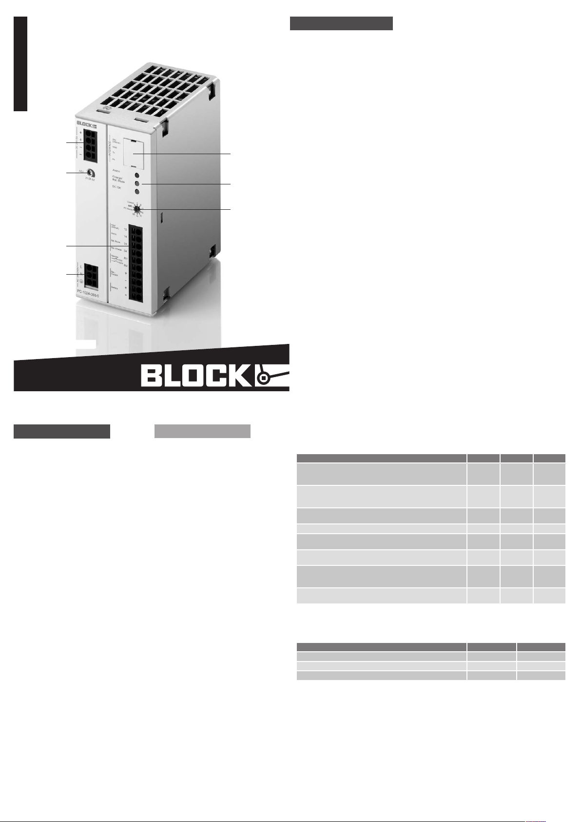
Geräteanschlüsse und
Bedienelemente
Fig. 1
DC - Aus gan g 24 V, ge puf fer t
1
Abdeckung für Interfaceanschluss für
2
di e Date nver bin dun g zum PC
Einstellung der Ausgangsspannung
3
23 … 28,5 V DC
LED rot: Alarm
4
LE D gelb: Bat . Char ge / Ba t . Mode
LE D grün: DC OK
Einstellung der Pufferzeit
5
1 … 20 [min ] , PC- M ode , maxim al (∞),
individuell über Einstellungen
der Konfigurationssoftware (Custom)
Batterieanschluss, Signal- und Steu-
6
erkontakte
13 = Potentialfreier Sammeleingang
für Signalausgänge 14/24/34
14 = Alarm (default=aktiv low)
24 = Bat. Mode (default=aktiv high)
34 = Bat . Charge (default=aktiv high)
R1 / R2= Fe rna bsc hal t ung im Puffer betrieb
Bat. Control (+-) = Steuerleitungen für
„Battery Control“
Battery (+-) = +24 V / 0V Anschluss
für Batteriemodul
AC - Ein gan g (10 0 … 24 0 V AC)
7
english
Equipment connections and
operating elements
Fig. 1
DC - Outp ut 24 V, bu f f ere d
1
Cover for interface connection for
2
communication to PC
Ou t put vo ltag e set t ing
3
23 … 28,5 V DC
LED red: Alarm
4
LE D yell ow: Ba t . Cha rge / Ba t. Mod e
LE D gree n: DC OK
Bu f f e r tim e sett i ng
5
1 … 20 [min ] , PC- M ode , maxim al (∞),
individually via
software (Custom)
Battery connection, Signal- and
6
control contacts
13 = Potenzial-free summation input
for 14/24/34
14 = Alarm (default=aktive low)
24 = Bat. Mode (default=aktive high)
34 = Bat . Charge (default=aktive high)
R1/R2= Remote shutdown in buffer
mode
Bat. Control (+-) = Control lines for
„battery control“
Battery (+-) = +24 V / 0V battery
module connection
AC - Inp ut (1 00 … 240 V AC )
7
Signalisierungen
LED
Beschreibung LE D grü n LE D gel b LED rot
USV arbeitet im Normalbetrieb
Au sga ngs span nun g > 20, 4 V
Ba tt eri e ist a ufg elad en un d OK
USV arbeitet im Normalbetrieb
Batteriemodul wird geladen
(L adu ng < 85 % der Ne nnk apa zit ät )
USV arbeitet im Normalbetrieb, kein Batteriebetrieb möglich
(P räs enz tes t neg at iv od er Fe rnab sch alt ung R1/ R2 ak tiv )
USV arbeitet im Normalbetrieb Akkutausch empfohlen an aus blinkt (2Hz)
USV arbeitet im Batteriebetrieb
Batteriespannung > 20,4 V
USV arbeitet im Batteriebetrieb
Batteriespannung <= 20,4 V
Tief entladun gsschut z der USV ha t den Ba tterieb etrieb been det
(Batteriespannung <= 19,2V)
Nu r die S igna lis ier ung wi rd f ür ma x. 10 S tun den fo rt ges etz t
USV arbeitet im Batteriebetrieb,
DC A usg ang w urd e auf gru nd vo n Übe rst rom a bges cha lt et
Hinweis: Die Zustände der LED-Anzeige ist nicht veränderbar.
Signalausgänge
Zustand (Werkseinst ellung) Signalausgang Funktion
kein Batteriebetrieb möglich oder Akkutausch empfohlen Al arm 13 /14 akt iv lo w (0 V )
USV arbeitet im Batteriebetrieb Ba t. Mo de 13 /24 ak tiv high ( 24 V)
Batteriemodul wird geladen B at . Cha rge 1 3/3 4 ak tiv high ( 24 V)
Hinweis: Die Signalausgänge können über die Konfigurations- und Managementsoftware USVCONTROL
individuell mit Alarm-, Warnungs- und/oder Betriebszuständen belegt werden.
an aus aus
an an aus
an aus an
an blinkt (2Hz) aus
an blinkt (8Hz) aus
aus aus blinkt (2Hz)
aus X blinkt (2Hz)
Page 2
english english
deutsch
Product Description
The Combi-UPS PC-1024-050-0 provi des an uni n terr upt i ble 24 V DC vo ltag e at
a maximum load current of up to 5 A in both an error-free AC power supply network
an d in the even t of pow e r fai lur e . Th e pow er su pply unit and the elec t r oni c cha r ge- and
co n trol unit ar e hou sed in the sa me ho usi ng. In the ev ent of supp l y vol t age fail ure, bu ffer mode is activated without interruption. The duration of buffer mode is set
using a selector switch.
Read this first
Safety measures before installation
Thi s equ ipm ent is to be pr o t ecte d agai nst impr o per use. Al way s disc onn e ct the equi p me n t from the ma ins supp ly, be for e comm enci ng in stal lat i on or wiri n g.
Installation
Installation and commissioning may be carried out by qualified personal only. National
rules and regulations (e.g. VDE, DIN, EMC) have to be observed. The required minimum
sp aci ng to ne igh b ori ng co m pon ent s must be obse rved
to guarantee the required cooling.
To av oid faul t y si g na l is a tio ns, the ba t ter y mod ule shou ld be conn ec t ed co m pl e tel y bef o re ap pl y in g pow e r to th e de v ic e . For faul t free op era t ion th e con t acts
R1/R2 for the remote shot down should be shortened by a bridge or an (emergency)
switch.
The char ge an d cont r ol un it wil l det e c t the ba t ter y modu le au t oma t ica lly, if bot h contro l lin es ar e conn e cted (B atter y Cont r ol) . The de v ice wi ll ad jus t the op tim al ch arge vo l tag e and ch arg e-cur ren t to prov i de op t imal ope rat i on co n dit ions for the batter y.
It is rec o mm e nd e d to co nn e ct th e con tro l lin es fo r an op t ima l bat t er y man a ge me n t. Ob ser ve th e cor rec t pol a ri t y!
If se ver al bat t erie s are co nne c t ed in para lle l , the bo th con trol line s sho uld be conn ected to only one of th e batt e ries .
In or der to gua r ant e e ef fec t i ve co o lin g, th e unit must be vert i cal l y ins t all ed su ch. To
reduce EMI and thermal strain DC-UPS modules and their battery modules should be
installed at least 50cm away from commutating chokes! Interface, signal and control
leads (e.g. R1/R2 and C+/C- control circuit) must be no longer than 3 meters and
must not be laid directly in parallel to power leads or cables (especially leads between
frequency converter and motor or frequency converter and commutating choke). DC
po w er le ads ar e not allo w ed to ex cee d 10 m. To minimize EMI th e dist a nce to thos e
leads should be at least 10 cm. Battery modules should be connected low-resistively
an d in a co o l pla ce (in cubi cle s usually at the lo wer end).
Anschluss
Eingang (7):
Zum Geräteschutz ist eine interne
Sicherung vorhanden. Ein zusätzlicher
Geräteschutz ist nicht erforderlich. Für
den Betrieb an zwei Außenleitern eines
Drehstromsystems muss eine allpolige
Trennvorrichtung vorgesehen werden.
Au s ga ng (1 ):
Die eingestellte Ausgangsspannung beträ gt be i Aus lie f erun g 24 V DC ±1% . Am
Po t e nti omet e r (3) ist di e Aus gan gss pan nu ng vo n 23 bis 28 ,5 V DC eins t ell bar. Be i
Ausfall der Versorgungsspannung wird
der Ausgang vom Batteriemodul gespeist.
Batteriemodul (6):
De r Ansc hlu ss er f o lgt üb er di e Anschlussklemmen „Battery +/-“. Um die
intelligente Technology „Battery Control“
zu nutzen, müssen Sie zudem beide
Steuerleitungen (Bat.- Control +/-) für
die Kommunikation zwischen USV und
Batteriemodul installieren.
ACHTUNG: Für die Da uer der In s tal lation oder Wechsel des Batteriemoduls
muss die Sicherung am Batteriemodul
entfernt werden!
Signalausgänge (6):
Der Anschluss erfolgt über die Klemmen
“Alarm”, “Bat.-Mode” und “Bat.-Charge”. Alle drei Ausg äng e besi t zen eine n gem e ins amen potenzialfreien und strombegrenzenden Sammeleingang, der über die Klemme
“I npu t ” ver s org t werd e n mu ss.
Fernabschaltung (6):
Soll die angeschlossene Last am Ausgang
des Kombi-USV-Moduls während des
Batteriebetriebs nicht aus dem Batteriemodul versorgt werden, z.B. im NOT
AUS Betrieb, kann der Batteriebetrieb
außer Funktion gesetzt werden. Hierzu
ist die Verbindung zwischen R1/R2 zu
unterbrechen.
Connection
Input (7):
An internal fuse is provided for device
protection. Additional device protection
is not required. For operation using two
phase conductors of a three-phase
system, an all-pole disconnecting device
mu st be pr ovid ed.
Output (1):
The output voltage set upon delivery is
24 V DC ±1%. The output voltage can be
set from 23 V DC to 28.5 V DC on the
potentiometer (3). The output is supplied
by th e bat t e ry if th e sup ply vo ltag e fai ls.
Batt ery module (6):
Connection of the battery module takes
place via the connection terminal block
„B a t tery +/- “. To make use of in t ell ige nt
technology “Battery Control”, you must
also install both control lines for the
communication between the UPS and
battery module.
ATT ENTIO N: The fuse fo r the re cha r geable battery module must be removed
wh e n ins t all ing or repl aci ng th e modu le!
Signal outputs (6):
The sig nal outpu t s are conn e cted via the
„Alarm“, „Bat.-Mode“, and „Bat.-Charge“
ter min al bl ock s . All three outpu ts ar e
eq uip p ed wi t h a com mon poten t ial free
an d sho r t cir cui t proo f sum - inp ut, wh i ch
ha s to su ppl ied vi a the te rmi nal “Inp ut”.
Remote shutdown (6):
If th e conn ecte d load shou ld no t be su p plied from the buffer module in the event
that the AC voltage fails, the UPS can
be disabled via R1/R2. For a shutdown
the connection between R1/R2 must be
interrupted.
Signaling
LED
Descipsion LE D gre en L ED ye llo w LE D red
UPS is oper ating in mains mode,
Ou tpu t vol ta ge > 20. 4 V
Ba tt ery i s cha rge d and OK
UPS is operating in mains mode,
Bat tery is chargi ng
(c har ge < 85 % of no min al ca pac ity )
UPS is operating in mains mode, no battery mode is possible
(B att er y pre sen ce ch eck is fail ed or r emo te R1/ R2 a cti ve)
UP S is op era tin g in ma ins m ode , bat ter y rep lac eme nt is r ecom men ded on off Flashing (2Hz)
UPS is oper ating in buffe r mode ,
ba tt ery v olt age > 20 .4 V
UPS is operating in buffer mode,
ba tt ery v olt age <= 2 0.4 V
UP S pro tec ti on aga ins t to tal d isc har ge ha s ter min ate d bat ter y
Mode (Ba ttery vol tage <= 19.2 V)
continues indication for a maximum of 10 hours
UP S is op era tin g in bu ffe r mod e,
DC O utp ut is s wit che d off d ue to o ver c urr ent
Notice: An in divi dua l ass ign ment of the LE D ind icat o rs is no t pos sib le.
Signal outputs
St at e (de fau lt se tti ng) Signal output Function
no batt ery mode is possib le or bat tery repl acement is recom mended Al arm 13 /14 act ive lo w (0 V )
UPS is operating in buffer mode Ba t. Mo de 13 /24 ac tiv e hig h (24 V )
Ba tt ery i s cha rgi ng (ch arg e < 85 % of no mina l cap aci ty ) Ba t. Ch arg e 13 /34 ac tiv e hig h (24 V )
Notice: The sign al ou tpu t s can be par ame t e riz ed in div i dua lly usin g a se r vic e PC an d t he
UPS-CONTROL configuration and management software.
on off off
on on off
on off on
on Flashing (2Hz) off
on Flashing (8Hz) off
off off Flashing (2Hz)
off X Flashing (2Hz)
Funktionsweise
Ausgangsspannung (1):
Im Normalbetrieb beträgt die Ausgangsspannung der Einstellung des Potentiome t ers (3 ). Bei Ausf a ll de r Ver sor gun gsspannung wird unterbrechungsfrei auf
den Batteriebetrieb umgeschaltet. Die
Ausgangsspannung ist jetzt direk t von
der Batteriespannung abhängig und
be t räg t UBAT - 0,5 V.
Einstellung der Pufferzeit (5):
Die Einstellung der Zeit, die den Batteriebetrieb beendet, erfolgt über den
Wahlschalter (5) auf der Gerätefront.
Dabei kann zwischen festen Zeiten,
einer individuell programmierbaren Zeit
oder der Einstellung „PC-Mode“ gewählt
werden.
PC-M ode:
In dies e r Ein stel lun g folg t die Komb i USV einer parametrierbaren zeitlichen
Abfolge von „Verzögerungszeit“ (default:
60 Sek.), „PC-Herunterfahren“ (default:
120 Sek.) und „PC-Leerlaufzeit“ (default:
10 Sek.). Wahlweise kann ein beliebiger
Signalausgang für das Herunterfahren
des PCs konfiguriert werden. Hierzu ist
eine individuelle Parametrierung über
die kostenlose Konfigurations- und
Managementsoftware „USV-CONTROL“
erforderlich.
Interface (2):
Das Modul kann mit einem PC oder einer
übergeordneten Steuerung kommunizieren. Durch das halbsekündliche Aussenden aller Eckdaten ist es möglich, neben
der Visualisierung relevanter Daten,
auch auf kritische Betriebszustände zu
reagieren. Eine Parametrisierung kann
ebenfalls über diese Schnittstelle erfolgen. Um die Schnittstelle direkt nutzen
zu können, ist das Kommunikationskabel
PC-KOK1 optional erhältlich
Method of Operation
Output voltage (1):
In normal operation (mains mode) the
output voltage corresponds to the
setting on the Potentiometers (3). If
the supply voltage fails, battery mode is
activated without any interruption. The
output voltage is now directly dependent
on th e bat t e ry vo l t age and is UBAT - 0,5 V.
Buffer time setting (5):
The time setting for shut down the
battery mode can be set via the selector
switch (5) on the front of the device. It
can be chosen between predefined times,
a individual parametrable time or the
setting „PC-Mode“.
PC-M ode:
In „PC mode“, the UPS function follows
a chronological sequence „PC delay
time“ (default: 60 sec.), „PC-shut down“
(default: 120 sec.) und „PC-idle time“
(d e fau l t: 10 sec. ) t hat ca n be pa ram eterized via the sof tware and individually
optimized for the relevant IPC solution.
It performs a controlled shutdown and
restart automatically. A signal output
to sh utdo wn the PC can be set via configurations- and management software
„UPS-CONTROL“.
Interface (2):
The interface enables the device to
communicate with a PC or a PLC. The
device sends key data every 0.5 seconds,
enabling the visualisation of the data or
the reac t i on on criti c al op era t ion al co n ditions. The device may also be configured
via the interface. For direct use of the
interface, the optional communication
ca ble PC - KOK 1 is av ail abl e .
Page 3
deutsch english
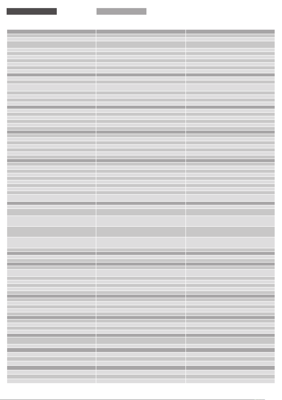
Technische Daten Technical data
Eingangsdaten Input data PC-1024-050-0
Eingangsnennspannung Nominal input voltage 10 0 - 24 0 Va c
Eingangsspannungsbereich Input voltage range 85 - 264 Vac (12 0 - 37 2 Vd c *)
Eingangsderating Input voltage derating
Nennfrequenzbereich Frequency range 47 H z - 63 Hz / 0 Hz
Ei ng an gs tro m (b ei Ne nn la st und Bat ter ie ge lade n / Max .) In pu t cur re nt (ma ins o pe ra tio n an d ba tte ry ch ar gi ng / max imu m) 1, 96 A / 2.2 2 A (1 00 Vac ) / 0, 95 A / 1. 10 A ( 23 0 Va c)
Einschaltstrombegr enzung Inrush current limitation < 30 A, N TC
Eingangssicherung, intern (Geräteschutz) In pu t fus e, int ern al (de vic e pr ote cti on ) 4 A
Empfohlene Vorsicherung, Leitungsschutzschalt er (Charakteristik) Recommended back-up fuse, circuit breaker (characteristic) 6 A, 10 A, 16 A (B ,C)
Tra nsie nte nüber sp an nu ng ss chu tz Var is to r Tra nsie nt su rg e vol ta ge pr ot ect ion va ris to r √
Anschlüsse Eingang Terminals input Pu sh- In , ma x. 2, 5m m²
Ausgangsdaten allgemein Output data
Ausgangsnennstrom Nominal output current 5 A
Auslösen von Leitungsschutzschaltern Tri ppin g of st ada rd cir cui t br eak er
Parallelschaltbarkeit zur Erhöhung der Systemverfügbarkeit Pa ra llel co nn ec tio n to ga in a hig her s ys te m rel iabi lit y
Restwelligkeit Ripple/noise ty p. 50 mVss
Rückspeisefestigkeit R es is tan ce to r ev er se fe ed ma x. 35 Vd c
Überspannungsschutz des Ausgangs (OVP) Over-voltage protection ty p. 38 Vdc
Anschlüsse Ausgang Terminals output Pu sh- In , ma x. 2, 5m m²
Ausgangsdaten Netzbetrieb Output data in mains operation
Ausgangsnennspannung No mi na l ou tpu t vo lta ge 24 Vd c ± 1%
Ausgangsspannungsbereich Output voltage range
Au sg an gs str om be gre nz un g Ko ns tan ts tro m Ou tpu t cu rr ent lim it ati on con sta nt cur ren t ty p. 6, 5 A
Verlustleistung (Nennlast und Batterie geladen) Power losses (nominal load, battery charged) 2 2 W (100 Va c) / 17W (23 0 Vac )
Wirkungsgrad (Nennlast und Batterie geladen) Efficiency (nominal load, battery charged) ty p. 88 %
max. Verlustleistung (Batterie wird geladen) Ma ximum p ow er los ses ( ba tte ry is cha rg ing ) 30 W (90 Vac )
Ausgangsdaten Batteriebetrieb Output data in battery operation
Ausgangsnennspannung (abhängig von der Batteriespannung) Nom in al out put vol tag e (d epe nd s on the bat ter y vol tag e) 24 Vdc
Ausgangsspannungsbereich Output voltage range
Au sg an gs str om be gre nz un g ele kt ron is ch Ou tpu t cu rr ent lim it ati on el ect ron ic t yp . 5, 5 A
max. Verlustleistung (Leerlauf/Nennlast) Max. power losses (sta nd-by/no minal load)
Fernabschaltung Remote shut-down √
Aufschalten kapazitiver Lasten Conn ec ti on of cap aci ti ve lo ad s max. 10.000µF
einstellbare Pufferzeit Ad ju st abl e bu ffe r tim e
Batteriemanagement Battery management
Ve rp ol sc hut z Sic he ru ng im Ba tte rie mo dul l ös t au s
La de cha ra kt eri st ik Charging characteristic
Ladestrom Charging current 0, 3 … 1, 0 A
La de sch lu ss sp an nu ng te mp er at urk om pe ns ie rt En d- of- ch arg e vo lt age tem pe rat ur e co mpe ns at ed 26 … 29, 5 V
Zy kl us fü r Ba tt eri epr äs en sp rü fun g 60 Se ku nd en Ba tte ry pr es enc e ch ec k/t ime i nt erv al 60 se co nds √
Zy kl us fü r Re st leb en sd au er prü fu ng 10 Minu te n Ba tte ry pr es enc e ch ec k/t ime i nt erv al 10 mi nu te s √
Tiefentladeschu tz Protection against total discharge 19 V
Schwelle Warnmeldung "Batteriespannung sehr gering" "B at ter y vol tag e ve ry low " ala rm sig nali ng th re sho ld 2 0,4 V
empfohlene Batteriemodule Recommended battery modules 1, 2 ... 1 2 Ah
"Parallelschaltung von Batteriemodulen / Max. 3 zur Verlängerung der Puffer-
zeit (Beide Steuerleitungen sind nur an einem Batteriemodul anzuschließen)“
Signalisierung Signaling
Statusanzeige LED grün/gelb/rot St atu s di spla y LED gre en/ ye ll ow/r ed
Potenzialfr eier Sammeleingang (strombegrenzter Summenstrom
fü r Signalau sgä ng e: Ala rm / Ba t. Mod e / Bat . Cha rg e) “
Signalausgang “Alarm““
Relaiskontakt offen: Störung/Austausch Batteriemodul
Signaloptionen konfigurierbar über Schnittstelle“
„Signalausgang “Bat. Mode““
Relaiskontakt geschlossen: Batteriebetrieb
Ausgang konfigurierbar über Schnittstelle“
„Signalausgang “Bat. Charge““
Relaiskontakt geschlossen: Batterie wird geladen
Ausgang konfigurierbar über Schnittstelle“
Anschlüsse Signalisierung Terminals signaling P ush -I n, ma x. 2,5 mm²
Schnittstelle Interface
RS 232 RS 232 √
Anschlüsse Schnittstelle (Anschlussstecker ist optional) Te rm in als in ter fac e (co nn ect or for in ter fac e is opt ion al ) WAG O-S eri e 73 3 / 0, 08 mm² .. . 0, 5 mm ² / AW G 28 . .. 20
Umwel t Environment
Lagertemperatur Storage temperature -2 5° C … +85 ° C
Umgebungstemperatur Operational temperature
Derating Derating -3 %/ K > +5 0° C
Konvektionskühlung Convection cooling
Luftfeuc htigkeit, keine Betauung Humidity, no condensation
Erforderlicher Mindestabstand (seitlich) Require d minimum spacing (left/right )
Erforderlicher Mindestabstand (oben/unten) Required minimum spacing (over/under) 50 mm
Allgemeine Daten General data
Sc hut za rt na ch IE C 60 52 9 De gre e of pro tec tio n acc . to IEC 60 529
Sc hut zk las se n ac h EN 6114 0 Pr ote cti on cla ss ac c. to E N 611 40
Ei ns at z in Be rei ch en mit Ver sch mu tz ungsg ra d 2 For installation in Pollution Degree 2 environment √
Zu m An sch lu ss K up fe rka be l mi t mi n. 75 °C ve rwe nd en Us e Co ppe r Co nd uc tio n on ly , ra te d 75 °C √
Überspannungskategorie Overvoltage category II
Normen Saf ety s ta nd ar ds
Sicherheit Safety
EMV EMC
Schutzkleinspannung (SELV/PELV) Sa f te ty ex tra -l ow vo lt age ( SE LV/ PE LV)
CE gem äß 201 4/ 30 /E U CE ac c. to 20 14 /3 0/ EU
Prüfzeichen Markings
UL UL
GL GL G L (Ge rm anis che r Ll oyd ) cl as si fi ed, Env iro nm en ta l cat ego ry : C, EMC 2
Re ve rse c on nec ti on pr ot ect io n (fu se of ba tte ry mo dule wi ll be tr ipp ed )
"P ar alle l con nec ti on of b at ter ie s / Max . 3 to in cre as e th e buf fer tim e (Bo th
co ntr ol -li ne s sh ou ld be con ne ct ed to onl y one of the b at ter y mod ul e)
Po ten zi al- fr ee summat io n in put ( sh or t cir cu it pr oo f summ ati oncu rr ent for sig nal -o utp ut s: Al ar m / Ba t. Mo de / Bat. Cha rg e)“
„Signal output “Alarm““
Relay-contac t opens: Alarm/Exchang e Battery
Si gn al opt ion s ar e adj us ta bl e via i nt erf ace “
„S igna l out put “ Ba t. Mo de“ “
Relay-contact closed: buffer mode
Si gn al opt ion s ar e adj us ta bl e via i nt erf ace “
„Signa l output „“Bat . Charge““
Relay-contac t closed: batter y charging
Si gn al opt ion s ar e adj us ta bl e via i nt erf ace “
√, onl y wi th ad di ti oal r ed unan cy mo du le for de cou pl in g, max . 5 A out put
1, 2, 3, 5, 10 , 15, 20 Mi n, PC- Mod e, Ma xi mum, ad jus ta bl e vi a int er fac e
An lau f be i -4 0 °C ty pge pr üf t De vi ce st art a t -4 0 °C ty pe- tes te d
UL /CS A 60 95 0 re cog ni se d (E 2132 14 ), U L 50 8 li st ed (E 21 90 22 )
UL- No te: O ut put dis co nn ec tin g me an s sh al l be pro vid ed dur ing i ns ta llat ion .
Mechanische Daten Measures and weights
Be fes tig un g au f Nor mp r of ils ch ie ne DI N EN 607 15 -T H3 5-15 /7,5 Mo un tin g on st an da rd ra il DIN EN 607 15 -T H3 5- 15 /7, 5 √
Gewicht Weight 0,8 kg
Ma ße (B x H x T) Ti efe ink lus iv e T H 35 -7,5 -DI N- Sch ie ne D ime ns io ns (W x H x D) De pt h inc l. DI N 35 -7.5 ra il 60 x 127 x 12 6 mm
Bestellnummern Order Number
Kombi-USV Combi-UPS PC-1024-050-0
Anschlusstecker für Schnittstelle, optional Connector for interface, optional
Kommunikationskabel für Schnittstelle, optional Communication cable for interface, optional
* Für DC Eingangsspannung ist eine geeignete DC- Sicherung erforderlich. * For DC input voltage suitable DC fuse required.
-1,5 % /V ac < 110 Vac
-1 % / Vd c < 15 0 Vd c
ma x. B4
current
23 – 28, 5 Vd c
UB AT - 0, 5 V (27,5 - 19 Vd c)
3, 2 W / 5,2 W
√
IUoU
√
√
ma x. 30 V / 200 mA
ma x. 30 V
ma x. 30 V
ma x. 30 V
-2 5° C ... +70° C
√
5 … 96 %
0 mm
IP 20
I
EN 615 58 -2 -16 , EN 60 95 0
EN 612 04 -3
EN 609 50 (SE LV), EN 602 04 (PELV )
√
PC-CON1
PC-KOK1
Page 4
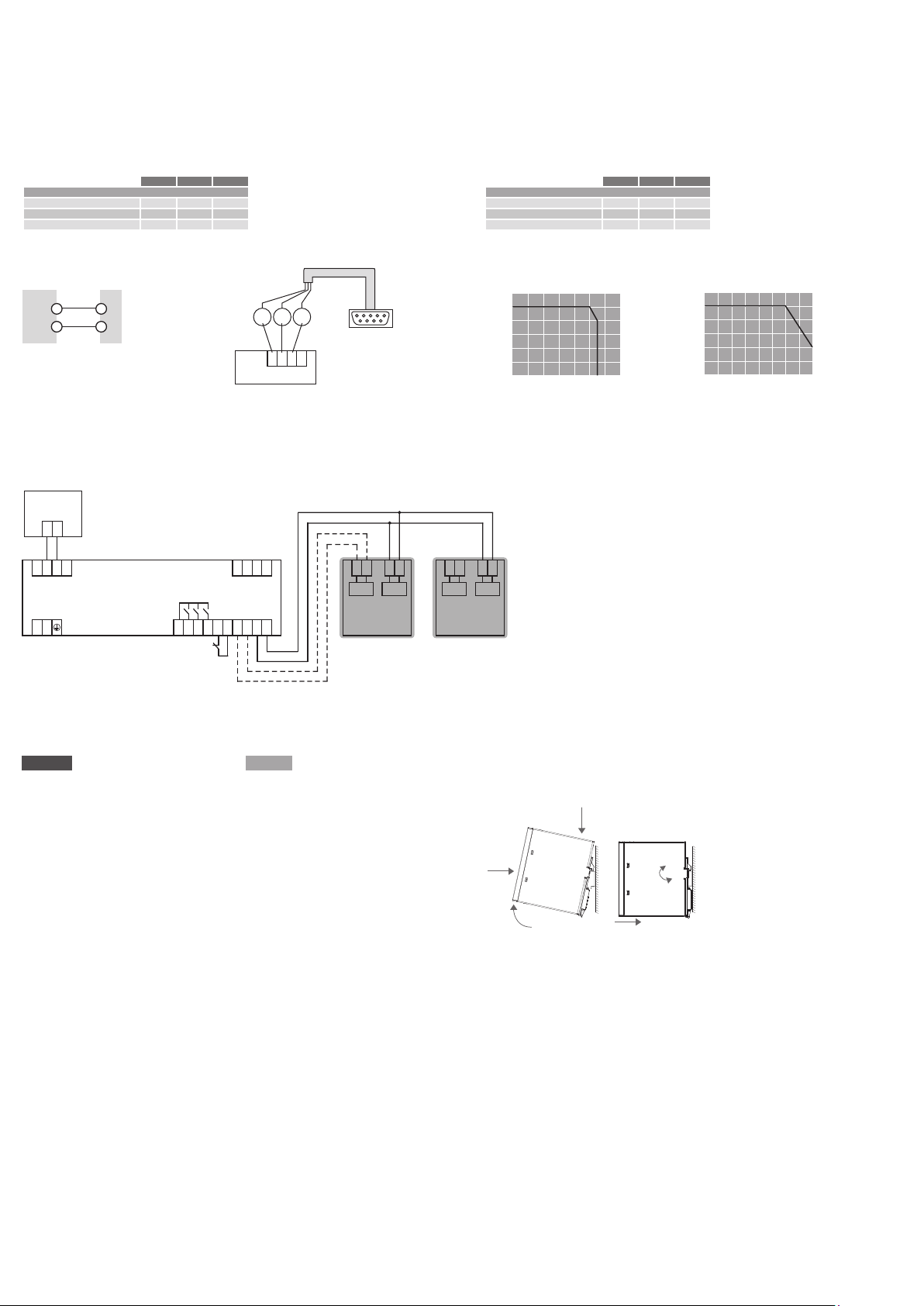
Auslösen von Standard- Leitungsschutzschaltern
Fig. 4
Die aufgeführten Leitungslängen sind experimentell bei ca. 25° C ermittelt worden. Sie
dienen als Richtwert für die Auslegung der DC-seitigen Absicherung durch Leitungsschut zschalter und sollten in der jeweiligen Applikation kundenseitig überprüft werden.
Fast tripping of standard bi-metal circuit breakers
Fig. 4
The specified cable lengths are theoretical values only and were determined in
respect to approx. 25° C. They serve only as a guide for determining the protection
thr oug h a stan dar d circ uit br eak er an d mus t be ver i fied in the re spe c tive appl icat i on.
Kabelquerschnitt (mm²) 0,75 1,5 2,5
Art.-Nr.
PC-1024-050-0
Leitungslänge mit LS B2 20 m 40 m 40 m
Leitungslänge mit LS B3 20 m 40 m 40 m
Leitungslänge mit LS B4 20 m 40 m
Fig. 4
1
–
2
+
DC OUT
Leitung 1 + 2 = Leitungslänge
Conducter 1 + 2 = Cable length
Buffered
load
-
+
--
+ +
IN
L N
LOAD
Verdrahtung
Wiring
OUT
PC-1024-050-0
Interface
13 14 24 34 R1 R2
Input
Bat. Mode
Bat. Alarm
BUFFERING
Bat. Charge
ON/OFF
Remote
1Tx2Rx3
Remote
+ +
Interface
Bat. Control
TxPC RxPC
4
GND
+24V
Bat. Control
Battery
--
1Tx2Rx3
Battery
Cable cross-section (mm²) 0,75 1,5 2,5
Art.-Nr.
PC-1024-050-0
Cable length with CB B2 20 m 40 m 40 m
Cable length with CB B3 20 m 40 m 40 m
Cable length with CB B4 20 m 40 m
Ausgangskennlinie
Output characteristic
U
/%
out
Batt ery
modul
100
80
60
40
20
0
0 20 40 60 80 100 120
I
/%
out
T
Pi n 2 = RxP C
Pi n 3 = TxPC
4
+24V
GND
Pi n 5 = GND
- -
- -
+ +
+ +
BAT BAT
CTRL CTRL
Batt ery
modul
1,2
/%
I
N
1,0
0,8
0,6
0,4
0,2
0,0
0 25 50
-25
Temp. (°C)
70
deutsch english
Montage
Fig. 2
AUF TRAGSCHIENE AUFRASTEN
I) Gerätevorderseite leicht nach oben
drehen
II) Auf Hutschiene aufset zen
III)
Bi s zum An sch lag nach un ten sc hie ben
IV) Unten gegen die Befestigungsebene
drücken (klick)
V) Leicht am Gerät rütteln, um Verrie-
Mounting
Fig. 2
SN A P ON SU PPOR T RAIL
I) Tilt the unit slightly rearwards
II) Fit the unit over top hat rail
III) Slide it downward until it hits the stop
IV) Press against the bottom front side
for locking (click)
V) Shake the unit slightly to check the
locking action
gelung zu prüfen
Fig. 2
II
III
V
I
IV
 Loading...