

Page 1
PVUA 24
USV Lade- und Kontrolleinheit
UPS charge- and control unit
block.eu
KAPVUA 2015•05
Allgemeine Funktionen
und Anwendungsbereiche
General operation
and applications
Das Modul ist eine Lade- und Kontroll einhei t für
die Verwendung von Blei-Gel-Batteriemodulen zur
Sicherstellung einer unterbrechungsfreien Stromverso rgung. Bei Ausfall der Versorgungs spannung
wird das Batteriemodul unterbrechungsfrei auf den
DC 24V Aus gan g ge sch al tet . Das Modu l is t wer ks eitig vorkonfiguriert und ist bei korrekter Verdrahtung
sofort einsatzbereit.
Th e m od ule is a ch arg e- an d co ntr o l un it fo r l ea dacid batterie s for guaranteeing an uninterrupted
supply of powe r. In case of fai lure of the main power,
the batt ery modul e will be switched to the DC 24V
output without interruption. The device is preconfigured at the fact ory and opera tes, if wired correc tly,
immediatel y without any restric tions user settings.
Abschalten der gesamten
Anlage
Switching off the whole
system
Ein gezieltes Abschalt en der Anlage ist im
Pufferbetrieb unter folgenden Bedingungen möglich:
1. Die am Gerä t eingest ellt e Zeit ist abgelaufen
(Werkseinstellung: dauerhaft)
2. Der Tiefentladeschutz des Batteriemoduls wird
aktiviert. (Die Batteriespannung sinkt auf unter
18 ,5 Vdc)
3. Die Kontakt verbindung 6 und 7 an der
Obers eite des Moduls wird
geöffnet.
Swit ching of f of a buffere d system is possib le under
the following conditions:
1. The set buf fer -tim e is run down
(factory setting: continuous)
2. The deep discharge protec tion of the
accumulator module is activa ted. (T he
battery voltages drops under
18.5Vd c)
3. Disconnecting con tacts 6 and 7 at the
up per sid e of th e mod ul e.
Installation
Installation
Sicherheitsmaßnahmen vor der
Installation
Das Betriebsmittel ist vor unzulässiger Beanspruchung zu schützen. Das Betriebsmittel immer im
spannungsfreien Zustand montieren und verdrahten.
Installation
Die Installation und Inbetriebnahme darf nur von
entsprechend qualifiziertem Personal durchgeführt
werden. Dabei sind die jeweiligen landesspezifischen
Vorsch riften (z.B. VDE, DIN, EMV ) einzuhal ten. Es
ist kein Mindes tabstand zu benachbart en Teilen
erforderlich. Bevo r da s Mod ul mit Sp annun g ve r-
sorgt wird, sollte das Batteriemodul vollständig
angeschlossen sein, um Fehlsignalisierungen zu
vermeiden. Für den fehlerfreien Betrieb müssen
ferne r die Kontakte 6 und 7 an der Unterseite des
Moduls für die Fern abscha ltung ent wede r über eine
Brücke oder einen (NOT) AUS- Schalter geschlo ssen
sein.
Angeschlossene Batteriemodule werden automatisch erkannt, sofern beide Steuerleitungen
für die Kommunikatio n zwischen den Modulen mit
korrekter Polarität angeschlossen sind.
Dynamische Anpa ssunge n wie der optimale
Ladestrom pro Batteriemodul oder eine temperaturabhängige Ladespannung werden automatisch
je nach verwendetem Batteriemodul eingestellt
und maximieren nachhaltig die Lebensdauer der
verbauten Akkumulatoren.
Für eine optimale Versorgung der Akkumulato ren wir d de r Aut om ati k- Bet ri eb mit an ge schlossenen Signalleitungen empfohlen.
Di e Po lar it ät is t zu be ac hte n.
Bei Parallelschaltung von mehreren Batteriemodule n sind die Signallei tunge n nur an einem
Batteriemodul anzuschließen. Einstellungen sind an
der Lade- und Kontrolleinheit für den Parallelbetrieb
von Batteriemodulen nicht nötig.
Bei Anschluss eines Relais an die aktiven DC 24
V-Signalausgä nge muss zwing end eine Freilaufdiode
vorhanden sein. Die Ausgänge sind maximal mit 25
mA belast bar. Das Gerät ist vertikal zu montieren.
Um Störeinkopplungen und thermische Beanspruchung zu minimieren, sollen DC-USV-Module und
zugehörige Batteriemodule mindestens 50 cm
entfernt von Kommutierungsdrosseln installiert
werden! Schnittstellen-, Steuer- und Signalleitungen
(z.B . buffering ON/OFF Steuer leit ung) dürf en nicht
länger als 3 Meter sein und nicht direkt paral lel
zu Leistungsleitungen (insbesondere Leitungen
zw isc he n Fre que nzu mr ich t er und Mo t or sowi e F re quenzumrichter und Kommutierungsdrossel) verlegt werd en. Um Störe inkopplungen zu minimi eren,
soll zu diesen Leitungen ein Abstand von mindestens
10cm eingehalten werden. Batteriemodule sollen
niederohmig ver draht et und an einem kühlen Ort
insta llier t werden (bei Sch altschränken in der Regel
ganz unten).
Ausgang:
Output:
Der Ausgang ist durch eine interne Diode vom
Eingang entkoppelt. Dadur ch ist sicher gest ellt ,
dass die gepuf fer ten Last en von den ungepuf fer ten
entkoppelt sind. Die gespeicherte Energie
wird nur an den Ausgang abgeg eben. Es wird
empfohlen, alle übrigen Last en, die bei Ausfall der
Versorgungsspannung keine Pufferung benötigen
(„Unbuffer ed Load“), parallel zur Stromversorgung
anzuschließen. Dies verlängert die Pufferzeit, da
diese vom Ausgangsst rom abhäng t.
Der Ausgang wird kontinuierlich stromüberwacht.
Bei Überschrei tung des Nenns trom es wird der
Ausgang zyklisc h für ca. 10 Sekunden abgeschalt et.
Nach der Zwangsabschal tung erf olgt eine erneute
Überprüfun g des Ausgangs. Sollte die Überla st
weit erhin vorhanden sein , schalte t sich der Ausgang
so la nge zykl isc h ab, bis di e Üb e rl ast u ng beho ben ist.
Safety measures before installation
This equip ment is to be protec ted against imprope r
use. Alwa ys disconn ect the equip ment from the
mains suppl y, before commencin g installation or
wiring.
Installation
Installation and commissioning may be carried
out by qualifi ed personal only. National rules
and regulations (e.g. VDE, DIN, EMC) have to be
obser ved. There is no minimal distanc e to other
part s require d. To avoid faulty signal isations, the
battery module should be connected completely
be for e ap ply in g po wer to th e dev ic e. Fo r fa u lt
free operatio n the contac ts 6 and 7 for the remo te
swit ch off on top of the device should be shortened
by a bridge or an (emergency) swit ch.
The charge and control unit will detect the bat ter y
module aut omatically, if both contro l lines are
conne cted . The device will adjust the optimal
charge-voltage and charge-curr ent to provide
optimal operation conditions for the battery.
It is recommended to connect the control line s
for an optimal battery management. Obser ve
the correct polarity!
If severa l batter ies are conne cted in parallel, the
both control lines should be connect ed to only one of
the batt eries. If a relay is connect ed to the activ e 24
V outputs, it is mandator y to connect a free wheeling
diode to it. The max imal outpu t current is 25 mA.
In order to guarantee eff ective cooling, the unit
must be verti cally installe d such. To red uce EMI and
therm al strain DC- UPS module s and their battery
module s should be install ed at least 50cm away
from comm utat ing chokes! Interf ace, signa l and
control leads (e.g . buffe ring ON/OFF control circuit )
must be not longer than 3 meter s and must not
be laid direct ly in parallel to power leads or cables
(especially leads between frequency converter and
motor or frequenc y converter and commut ating
choke ). To minimize EMI the distan ce to those leads
should be at least 10cm. Batter y modules should
be connec ted low- resistively and in a coo l place (in
cu bic les usu a ll y a t th e low er en d) .
The outpu t is decoupled from the input by means
of the inter nal diode. The int ernal diod e guarantees
that the buf fered loads are decoup led from the
unbuf fer ed loads. The stored power is only deli vered
at the output . We recommend that all other loads
not requiring buf fering in the event of a failure of
the supply vol tage („Un buf fered Load“) should be
conne cted parallel to the power supp ly unit. This
extends the buffer time, as it depends on the output
current.
The outpu t current is continuously monitored.
Exce eding the nomin al curren t causes a periodic
shuto ff for about 10 seconds. The cycli ng of the
power con tinue s until no over-curre nt is detect ed
during engaging of the device.
Neue Funktionen mit Einführung intelligenter
Batteriemodule (mit „Battery Control“):
New features with the introduction of these intelligent
battery modules (with “Battery Control):
automatische Erkennung angeschlossener
r
Batteriemodule
Zuverlässiges Frühwarnsignal bei geringer
r
Restlebenserwartung der Batterien
maximale Lebensdauer durch temperaturge -
r
führtes Batteriemanagement
Anzei ge des aktuel len Ladezustan ds und der
r
Restlaufzeit der Akkumulatoren.
Automatic det ection of connected batt ery
r
module
Reliab le early warning signal when battery lif e
r
expectancy is declining
Ext ended lif e expect ancy thr ough temperatu re
r
controlled battery management
Addit ional informat ion about charge status and
r
remaining time of batteries.
T T
Hinweis
Unterstützung von intelligenten Batteriemo dul en mi t „B att ery Co nt rol “ ab 06/ 20 1 2
(Fertigungsauf tragsnummer ab 214966)
Der Verwendung von Batteriemodulen mit
„B a tte r y Co ntr o l“ is t au ch mi t Lad e- un d Ko ntrolleinheiten möglich, die „Battery Control“
noch nicht unterstützen. Auch Batteriemodule
ohne „Bat tery Control “ können mit Lade- und
Kontrolleinheit en mit „Battery Control“
betrieben werden. In beiden Fällen ist lediglich
das temperaturgeführte Batteriemanagement
akti v.“
Notice
Su pp ort of int ell ig ent bat ter y mod ul es wi t h
„Bat tery Control “ for date of production aft er:
06/2012 (and product ion lot number 214966
or higher)
It is p os sib le to use ba t te ry mo dul es wi t h “B atte ry Co ntr ol” toge t he r w it h cha rg e- an d con trol unit s withou t “Batt ery Control” suppo rt. It
is also possible to use battery modules with out
“Bat tery Control ” togeth er with charg e- and
control units with “Batt ery Cont rol” support.
In both cases only the temperature-tracked
ba t t er y manag em ent wil l be ac t iv e.
Page 2
Konfiguration des Moduls
Configuration of the module
Das Modul lässt sich dir ekt am Gerät und über die
Schnittstelle durch die kostenlose Konfigurationssoftware parametrisieren. Folgende Einstellungen
sind möglich:
Zuschaltschwelle (über Software einstellbar). Bei
r
Unterschreit en der Eingangsspannung unterhalb
der Zuschaltschwelle wird die Energie unterbrechungsfrei vom Batteriemodul zur Verfügung
gestellt. (Werkseinstellung: 22 Vdc)
Pufferzeit (über Modul oder Software einstell-
r
ba r) . N ac h A bl au f der Zeit wi rd di e An l ag e im Pu f f er betrieb abgesc haltet. (Wer kseinstellung: 999 s, d.h.
dauerhaft, bis die Anlage aufgrund des Tiefentladeschutzes des Batteriemoduls zwangsabgeschaltet
wird)
Rücksetzen der Betriebsstunden des Batte-
r
riemoduls (über Modul oder Software einstellbar).
Beispielsweise kann nach einem Akkutausch der
Betriebsstundenzähler zurückgesetzt werden.
Grenzwert e für Strom- und Spannungsüber-
r
wachun g (über die Soft ware eins tellb ar). Durch die
interne Strom- und Spannungsüberwachung des
Ei n- un d Au s ga ng s kan n ei ne pr äve nti ve Fu nk tio ns überwachung durchgeführt werden. (Werkseinstellung: Iout=Inenn,
Uin/Uout=20,4 Vdc)
Deaktivierung des temperaturgeführten
r
Batteriemanagements (über Modul oder Soft ware
einstellbar). Die Ladespannung kann alternativ
direk t zwischen 26 und 29,5 Vdc eingestellt werden.
(Werkseinstellung: Aktivierung des temperaturgeführten Batteriemanagements)
Konfiguration der Signal- bzw. Meldeausgänge
r
(über die Software einstellbar). Die Signalausgänge
1 und 2 auf der Fron tseite des Moduls sowi e der
potenzialfreie Meldekontakt an der Oberseite lassen
sich auf bestimmte Ere ignisse oder Störungen
indiv iduell umko nfigu rieren. Siehe Kapitel
Signalisierung.
Parametrisierung am Gerät sperren (übe r die
r
Software einstellbar). Um Fehleinstellungen durch
unaut orisierte Per sonen am Gerät zu unte rbinden,
ka nn di e Pa ram et ris ie run g am Ge rä t g es per r t we rden. (Werkseinstellung: Parametrisierung am Gerät
erlaubt)
The parame ters of the module can be set on the
devic e or by using the free of charge con figuration
software with the inter face . The following settings
are possible:
Activation threshold (adjustable via Software)
r
If the input volt age drops belo w the activa tion
threshold, the energy will be provided by the battery
wi tho ut in t er r up t io n ( de fau lt : 22 V)
Buf fer- time (adjustab le on device or via
r
Software)
Durat ion of the buff ering . After this time the
buffering will be switche d off and there fore the
conne cted sys tem is switc hed off too. (defaul t:
999s, this mean s that the buffering is swit ched off
af ter th e de ep di sc har ge of the ba t ter y is de t ec ted )
Reset ting the operatin g hours of the batte ry
r
(adjustable via Software)
Can be used for reset ting the operating hour s if the
ba t t er y has b ee n e xc han ge d.
Limit s for the voltage and current monitorin g
r
(adjus table via Softw are) The int ernal volt age and
curre nt monitoring enabl es a preventive funct ion
monit oring of the devi ce. (def ault: Iout=Inominal,
Uin/Uout=20.4 V)
Deactivation of the temperature-
r
controlled battery management (adjustable on
devic e or via Software) The charge voltage may
be adjusted between 26 and 29.5 Vdc (default:
Temperature controlled battery management is
activated)
Configurat ion of the signal and noti fyin g
r
outpu ts (adjus table via Software). The sign alisat ion
outpu ts 1 and 2 at the front and the potential-free
cont act at the upper side may be configured to
reac t on different error s or events (see chap ter
Signalisations)
Locking of configurati on (adjust able via
r
Softwar e). To prevent the change of the set tings
on the device by unaut horiz ed persons, the
conf iguration can be locked. (defaul t: configuration
not locked)
Mögliche angezeigte Störungen nach dem erstmaligen
Einschalten der Anlage
Possibly signalized faults during initial startup
Rote LED leuchtet:
Die Konta kte 6 und 7 an der Unte rseite des
r
Moduls sind nicht verbunden. Sie dienen der Fernabschaltung der Anlage und sind für den fehlerfr eien
Betrieb notwendig.
Da s Bat ter i em odu l is t nic ht ko rr ekt an ge -
r
schlossen oder die Sicherung im Batteriemodul hat
ausgelöst.
In beiden Fällen wird der Fehler „buffer mode not
possible“ signalisiert.
Gelbe LED leuchtet:
Da s Bat ter i em odu l is t nic ht vo ll stä nd ig au fg ela -
r
de n . Di e se War nung wi r d au t om a ti sch zur ü ck gesetz t, wenn die Akku mulat oren minde stens zu 85 %
geladen sind.
Die beiden Signalleitungen für die Kommunika-
r
tion zwischen Lade - und Kontrol leinheit und dem
Batteriemodul sind nicht korrekt angeschlossen,
so dass keine Temperatur aus dem Batteriemodul
gelesen werden kann . Die Warnung „no temper atur e
track ing“ wird angezeig t. Alte rnati v kann das
temperaturgeführtes Batteriemanagement direkt
am Modul oder durch die Konfigurationssoftware
deaktiviert werden.
Die Restlebenserwartung der Akkumula-
r
tore n ist zu gering. Die Warnung „acc u exchange
recommende d“ wird angezeigt. Es wird empfohlen,
die Akkumulatoren paarw eise nach Auf treten der
Warnung so schne ll wie möglich ausz utaus chen, um
einen gesicherten Pufferbetrieb weiterhin aufrecht
zu erhalt en.
Re d LED tur ned on:
Co n ta cts 6 and 7 on the bo t t om of
r
th e m od ule are no t clo sed . T he co nt act s
ma y be us ed fo r rem ote sw itc h o f f of th e
de v ic e and are ne ed e d fo r the corr e ct
operation.
Th e b at ter y mod ul e i s no t c on n ec ted
r
co r re ctl y or th e in ter nal safe ty fu se is
tripp ed. The fault „bu ffe r mode not possible“ will be
signaled.
Yel low L ED turn ed on:
The batt erie module is not charged compl etel y.
r
The warnin g „accu charge <85 %“ will be signaled.
If both cont rol lines (CT RL) for the
r
commun ication between the module s are not
conne cted , a no temperat ure track ing”warnin g is
indicated.
The use of the temper ature controlled charging
is recommended to maximise the life time of the
lead- acid battery. Alt erna tively this funct ion can be
deactivat ed at the modul direc tly or with the free of
charge configuration software.
The batt ery life expect ancy is very low.
r
The warnin g „accu exchan ge recommended“ will be
showed. The batte ry should be exchan ged in a short
ti m e to gu ar ant e e th e rel ia ble b uf fer op er ati on.
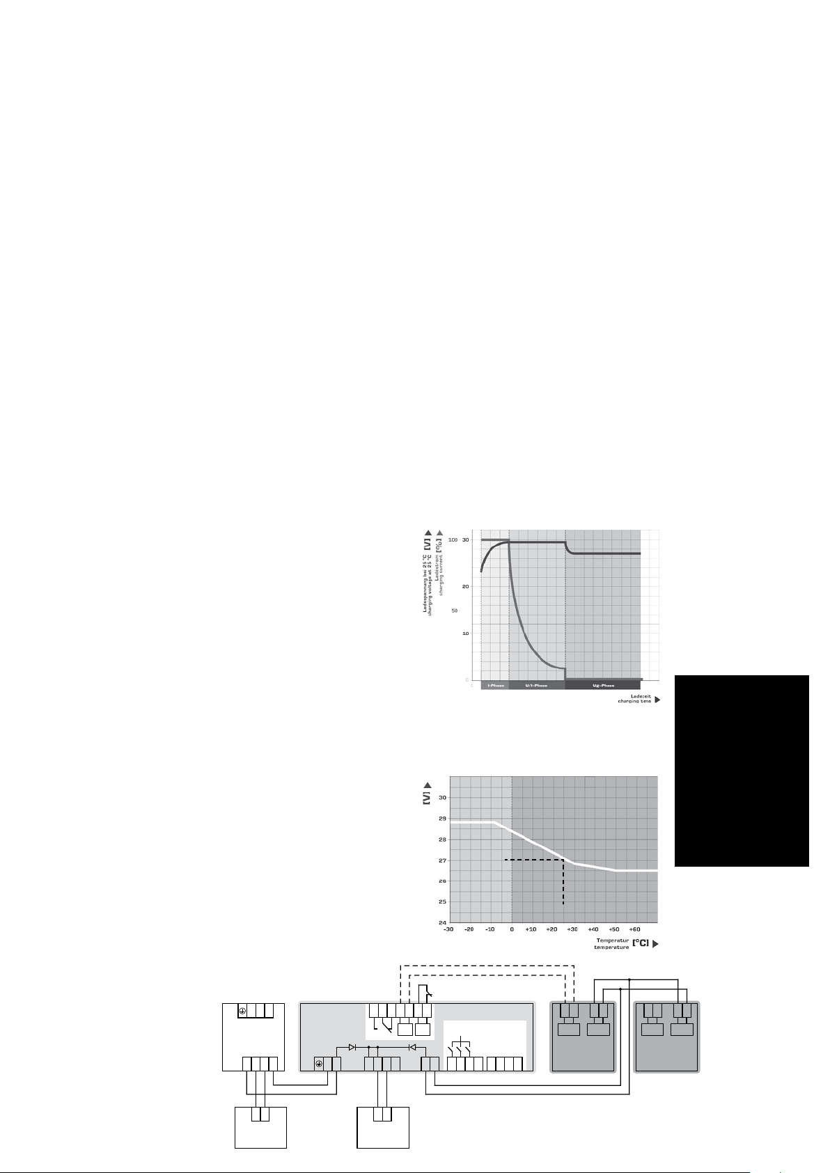
Verdrahtung PVUA 24
Wiring PVUA 24
L1 L2L2 4 51 62 73
IN
OUT
Power
Supply
+
+
-
-
PV UA 24
- -- -
OUTIN
+
-
+
REMOTE
CTRL SIGNAL OUTPUTS
ON/OFF
BAT
+ + +
Signalisierung:
Signalisation:
Für die Signalisierung der Betriebszustände stehen
drei LED, drei aktive DC 24 V-Signalausgänge , ein
potenzialfreier Wechselkontakt sowie eine serielle
RS-232 Schnittste lle zur Verfügung.
Aktive DC 24 V-Signalausgänge
Da s Mo dul ist mi t 3 ak tiv en DC 24 V–
Signalausgäng en ausgest att et, die sich hint er einer
Schut zkappe an der vorderen Kuns tstoff abdeckung
befinden. Durc h die Konfiguratio nssof twa re lässt
sich die Funkt ionali tät der Ausgänge 1 und 2
individuell anpassen.
Potenzialfreier Wechselkontakt
Der potenzialfreie Wechselkontakt an der Oberseite
des Moduls ist intern mit der Funktionali tät des
akti ven DC 24 V-Signalausgangs 1 verknüp ft.
Durch die Konfigura tionssof twar e lässt sich
die Funktionalität individuell anpassen, um
beispielsweise eine Sammelstörungsmeldung zu
generieren. Werkseinstellung:
Im Normalbetrie b ist das interne Relais aktiviert
r
(Kontak te 1 und 2 sind gesc hlossen).
Im Puff erbetrieb wir d das interne Relais inakti v
r
(Ko n ta kte 2 un d 3 si nd ge sc hlo ss en) .
Schnittstelle
Dank der seriel len Schnittstelle kann das Modul mit
einem PC oder einer übergeordneten Steuerung
kommunizieren. Durch das halbsekündliche
Aussen den aller Eckda ten ist es möglich, neben
der Visualisieru ng relevanter Daten, auch auf
krit ische Bet riebszust ände zu reagie ren. Eine
Parametrisierung kann ebenfall s über diese
Schni ttstelle er folge n. Um die Schnitt stel le direkt
nu t ze n zu kö nn e n, is t da s Kom mu n ik ati o ns ka bel PVKOK2 optional erhältlich.
Detektierbare Störungen
Das Modul kann verschiedene Störungen in der
Anlage erkennen, die über Signalausgänge oder
über die Schnittstelle ausgewertet werden können.
Am Gerät selbst lässt sich eine Fehle rdiagnose
durch führen. Im letzt en Bildschirmme nü ist
jeder möglichen Störung ein blinke ndes Segme nt
zugeordnet.
Ladekennlinie
Charging Characteristic
1 2 3
Temperaturkompensation
Temperature Compensation
Ladeerhaltungsspannung
Trickle charge voltage
BUFFERING
ON/OFF
27 Vdc
0010110111001101011
RS-232
+24 V
S1 S2 S3
RxPC
41 2 3 85 6 7
TxPC
25 °C
- -
+ +
+ +
BAT BAT
CTRL CTRL
+24 V
0 V
PV A 24
PV AF 24
For the signali satio n of the operating states of the
devic e three LED, thr ee activ e 24 V DC signalisation
outpu ts, a potential free con tact as well as a
RS-232 interf ace are availa ble.
Ac tive 24 V DC ou tpu ts
The devic e is equipped wit h 3 active
24 V DC outputs which are located behind the
prot ecti ve cover on the front panel. The functional ity
of output 1 and 2 can be set individua lly via the
configuration software.
Potential free changeover contact
The potential fre e changeover conta ct at the upper
side of the devic e is internall y combined with the
functional ity of the acti ve 24 DC signalisation output
1. This funct ionality can be set by the configuratio n
software, in example to genera te collectiv e
signalisations. Default sett ing:
During nor mal operat ion the internal relay is
r
act ive (c on nec tor 1 and 2 cl os ed)
During buf fer ing the inter nal relay is inact ive
r
(co nne ct or 2 an d 3 cl ose d)
Interface
The RS-232 interf ace enables the device to
commun icat e with a PC or a PLC. The device
sends key data every 0.5 seconds , enabling the
visual isati on of the data or the reacti on on critical
opera tional conditions. The device may also be
conf igured via the interf ace. For dire ct use of the
in t er fac e, th e opt i on al co mm uni ca tio n ca ble PVKO K 2 is avai la ble .
Detectable error conditions
The module is able to dete ct diff eren t error
condi tions which can be evaluate d though the
signalisation output s and the interf ace. The err or
condi tions can also be diagno sed on the device . On
the last graphical menu page a flashing segment is
as si gne d to an eac h err or co ndi t io n .
Hauptladung
1
(konstanter maximaler Ladestrom)
Haupt-/Voll-Ladung
2
(konstante Ladespannung)
Voll-/Erhaltungs-Ladung
3
(konstante Ladeerhaltungsspannung)
Initial charge period
1
(constant max. current)
Ma in ch ar ge pe ri od
2
(constant voltage)
Trickle charge period
3
(constant voltage)
T
Hinweis:
So fer n di e Lad e- und Ko nt rol leinheit kein Batteriemodul
automatisch erkennen kann,
oder der Automatik-Betrieb
manuell deaktiviert wird, wird
nu r na ch Ph as e 3 gelad en .
Notice:
If no battery module can
detected or the AutomaticDetection-Mode is disabled,
only phase 3 will be used for
charging.
- -
PV A 24
PV AF 24
Unbuffered
load
--
++
Buffered
load
Page 3
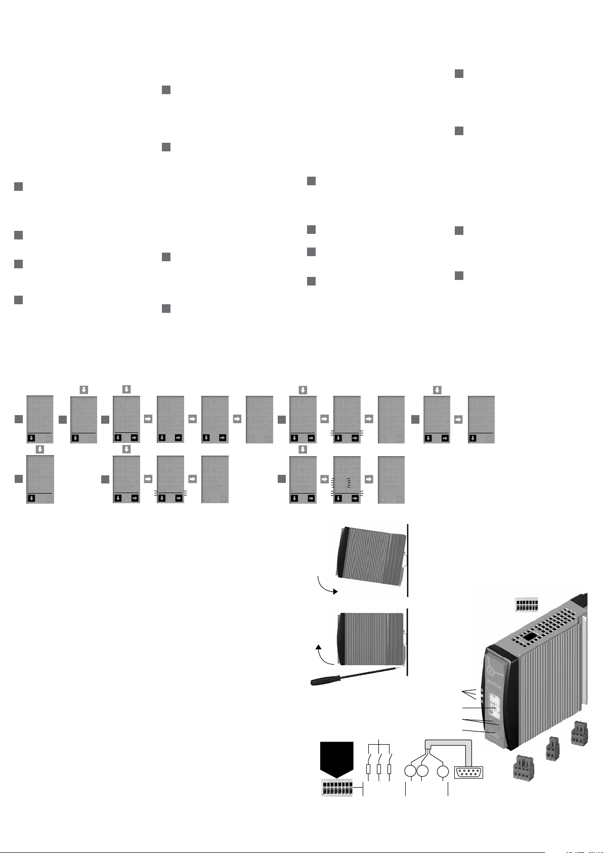
Anzeigen und Parametrisieren über das Display
Setting the parameters using the display
Allgemeine Funktionen
Allgemein: Nur wenn die Tasten-Symbole
Display aufleuchten, ist die jeweilige Taste auch aktiv.
Standardanzeige: Betätigt man für 30 Sekunden
keine Taste, schaltet das Modul automatisch zur
Standard-Anzeige zurück.
Reset: Betätigt man für 5 Sekunden beide Tasten
gleichzeitig, erfolgt ein Reset aller parametrisierbaren
Parameter auf die Werkseinstellung. Dabei werden
alle gespeicherten Min/Max-Werte sowie der
letzte Fehler zurückgesetzt.
Zeitlimit: Wenn zwischen den Eingaben (auch
während des Parametrisierens) länger als 30
Sekunden keine Taste betätigt wird, werden alle
gemachten Eingaben zurückgesetzt und es erfolgt ein
automatischer Wechsel zur Standardanzeige.
Update: Falls Parameter über den PC verändert
werden, entsprechen diese neuen Parameter
automatisch der Reset-Konfiguration. Die
Werkseinstellung wird überschrieben.
1
Standardanzeige
Zeigt die aktuelle Eingangsspannung, die Ausgangsspannung und den Ausgangsst rom an. Zusät zlich
wi r d in de r 2. Zeil e von obe n der aktu e ll e Lad ezu stand (im Normalbet rieb) bzw. die Restlau fzei t (im
Pufferbetrieb) angezeigt.
2
Ladespannung und -strom
Zeigt die akt uelle Lade spannung und den Ladestrom
an.
3
Minimal- und Maximalwerte
Die minimal gemessene Eingangsspannung und
de r max i ma l ge mes se ne Au sg an gss tro m we rde n
angezeigt.
4
Temperaturgeführtes Batterie-
management
In Abhängigkeit der Temperatur im Batteriemodul
werden die optimalen Ladeparameter automatisch
eingestell t. Es ist ebenfa lls möglich, eine konstante
Ladeerhaltungsspannung zu konfigurieren ( Phase 3
gemäß Ladekennlinie)
B = zum Deak tiv ieren des tem perat urabhängigen
Batteriemanagements
AB im LC-
A = temperaturabhängiges Batteriemanagement
(de)aktivieren (ON/OFF)
B = konstante Ladeerhaltungsspannung einstellen
(2 6 bis 29, 5 Vd c)
B = Änderung speichern
5
Pufferzeit
Die Pufferzeit kann eingestellt werden.
B = zum Ändern der Pufferzeit
A = Pufferzeit ändern
(10 Sek. bis 10 Min. / dauerhaft )
B = Pufferzeit speichern
6
Erkennung der Batteriemodule
Batteriemodule mit „Battery Control“ werden
autom atisc h erkannt und der Kapaz ität swer t wird
angezeigt. Wird anstel le des Kapazit ätswert es
für das verwendete Batteriemodul „---“ angezeigt,
so konnte kein Batteriemodul erkannt werden.
In diesem Fall wird der maximale Ladestrom zur
Ve r fü gun g ge ste l lt und di e Lad un g e rfo lgt mi t ko n stanter Ladeerhaltungsspannung ( Phase 3 gemäß
Ladekennlinie)
B = zum De ak tiv ier en de r au tom at isc hen Erke n-
nung von verwendeten Batteriemodulen
A = Erkennung (de)aktivieren (ON/OFF)
B = Änderung speichern
7
Betriebsstunden des
Batteriemoduls
Die Betriebsstunden des verwendeten Batteriemoduls könn en abgeles en werden und auf Null
zurückgesetzt werden.
B = zum Zurücksetzen der Betriebsstunden
8
Fehlermanager
Anhand des Fehlercodes (siehe auch Aufkleber am
Gehäuse) kann anhand der blinkenden Segmente
eine Fehleranalyse vorgenommen werden.
Der letz te Fehler wird fest gespeicher t, so dass
auch noch nach einem Neustar t des Moduls eine
Fehlerursache detektiert werden kann.
B = letzten Fehler anzeigen
A = mit di es em Be f eh l ( li nke Tast e) ko mme n Sie zum nä ch s te n Men üp unk t
A = pres si ng th e le ft bu tton mea ns mo ve to nex t men u poi nt
General functions
General: The buttons AB are only active when
the appropriate symbol in the display is alight.
Standard display: If no button is operated for 30
seconds the unit will return to the standard display
mode.
Reset: If both buttons are pressed simultaneously
for 5 seconds then all parameters settings will return
to the factory set condition. This means all saved
min/max. values and the last fault condition will
be reset.
Time limit: If between the input programming (also
parameter settings) a time interval of over 30
seconds has lapsed without pressing any button, then
all entries will be reset, and the display will return to
the standard display mode.
Update: If the parameters have been changed using a
PC then these settings will automatically be the reset
parameters. The factory settings will be lost.
1
Standard display
Shows the act ual input volt age, output volta ge and
output current.
Addit ional informat ion on 2. row: Charge stat us
(normal operation) and remain ing time of the
batteries (buffer operation).
2
Charging voltage and current
Shows the actual charging voltage and current .
3
Minimum and maximum values
The min. input voltage and the max. out put curre nt
are displayed.
4
Temperature tracked batterie
management
The devic e regulat es the optimal charge- volt age for
the batt ery modul e automat icall y. It is also possible
to adjust a fixed char ge-v oltage. (Only phase 3 will
be used fo r ch ar gin g)
B = to change the temperature tracked bat tery
management
A = to (de)activate temperature tracked batt ery
management (ON/OFF)
B = to adj us t a fix ed ch ar ge- vol tag e
(2 6 t o 29 .5 Vdc )
B = save changes
5
Puffer time setting
Th e t im e f or pu f fe r ope ra tio n c an be adj us ted .
B = to adjus t time for puff er operat ion
A = adju st puff er time sett ing
(10 seconds to 10 minutes / constant )
B = sav e puf fer ope rat i on
6
Detection of battery module
Batt ery modules with „Bat ter y Contro l“ will detec t
autom atically. The rate d capacit y will showed .
When displ ayed „-- -“instead of the capacity valu e,
no battery module was detected.
At this setting the maximal load current will be
su pp lie d. Th e ba tter y w il l be ch ar ged wi th a co nstant charging voltage (Phase 3 according to the
loading chart)
B = to change the automatic detection
A = to (de ) ac tiv ate th e de tec tio n (O N/O FF )
B = save changes
7
Operational hours of the battery
module
The opera tional hours for the accumul ator s inside
of th e ba tte ry mo du le ca n be di sp lay ed an d re set .
B = to r es e t th e ope ra tio na l hou rs an d se t i t to „0 “
8
Fault manager
A fault analysis can be made according to the
blinking segments of the display (see rat ings plate
on housing).
The last fault symptom will be auto matic ally saved,
so that even aft er a new start of the module a fault
analysis can be made.
B = sho w las t fa u lt co nd i ti on.
Ui [V]
25,4
!!
I
Uo [V]
1
24,6
Io [A]
8,03
Ui [V]
23,1
U.Lo
3
I.Hi
10,4
Io [A]
TEP
4
0n
120
BAT
Uo [V]
2
25,7
Io [A]
0,43
LED: Di e gr üne LED (a ) le uch t et , wen n ke in Fe h-
1
ler vorlie gt. Die gelbe LED (b) zeigt Warnungen
an. Die gelbe LED (b) blink t bei Puffe rbet rieb im
0, 4 S ek .-Tak t. Di e gel be LE D (b ) bli nk t bei ger inger Batt eriespannun g im Pufferbetrieb im 0,2
Se k .- Tak t. Di e r ot e LED (c ) ze igt Feh ler an.
Nach Rücksetzen der Akkulebensdauer angeschlossener Akkumodule der Baureihe PVA(F)
le uch t en alle LED fü r 5 S ek und en .
Display der Kontrolleinheit: Da s Par am etr i -
2
siere n über das Display wird rück seitig erklär t.
Tas ten: Linke Taste = vorwärt s im Menü, recht e
3
Tas t e = Pa ram et ris ie ren .
ACC: Akku-Anschluss
4
Signale: siehe Anschlussplan rückseitig
5
Eingang: IN
6
Ausgang: OUT
7
Montage: Se tze n Sie das Modu l mi t der Trag -
8
sc hie ne nfü hru ng an die Ob er kan te de r Trag sc hie ne an und ra st en Si e es na ch un te n ein .
Demontage: Ziehen Sie den Schnappriegel
mit Hilfe eines Schraubendrehers auf und
hängen Sie das Modul an der Unter kante der
Tragschiene aus.
Schnittstelle und Signalausgänge: Die
9
Schut zkappe ist zur Vermeidung statisc her
Entladungen nur unter Anwendung von ESDSchutzmaßnahmen abzunehmen.
Pufferbetrieb,
trieb möglich oder Akkutausch empfohlen,
3 inaktiv bei Abschalt ung durch Über strom,
12
per PC mit Soft ware,
potenzialfreiem Wechselkontakt,
munikationsein- und Ausgänge,
7 Eingangsspannung des Moduls.
Die Schnittst elle ist nich t galvanisch getrennt.
Ein geeignetes Adapterkabel (PV-KOK2) oder
den passenden Stecker (PV-CON) können Sie
über BLOCK bez iehen . Bei Anschlus s eines
Relais an einen Signalausgang muss zwingend
eine Freilaufdiode vorhanden sein.
2 Inaktiv, wenn kein Batteriebe-
Frei belegbare Ausgänge, konfigurierbar
1 Verknüpfung mit
bu.T
5
1 Inaktiv bei
568 Kom-
TEP
U.AC
SET STO
OFF
26.6
999
bu.T
SET
LED: Th e gre e n LE D ( a) li gh t s fo r nor ma l ope -
1
ration. The yellow LED (b) show s a warning. The
yellow LED (b) blinks in 0,4 sec. cycle, indicatin g
puffer opera tion. The yellow LED (b) blinks when
the batt ery volt age is low in puffer operatio n at
0,2 sec. cycl e. The red LED (c) indica tes a fault
condition.
Aft er reseting the lifet ime of connec ted bat tery
mo dul s fro m se ri es PVA (F) all LE D li ght up fo r
5 se c on ds.
Th e contr ol unit dis pla y: The parameter
2
adjust ment s are described on the back of this
leaflet.
Buttons: Left but ton = forwar ds in the menu,
3
ri ght butt on = to al te r par am ete r set tin gs .
ACC: accumulator terminals
4
Signals: see connection plan on the reverse
5
side
Input: IN
Output: OUT
7
Mounting: Place the module with the DIN rail
8
guide on the upper edge of the DIN rail, and snap
it in with a
downward motion.
Removing: Pull the snap lever open with the aid
of a screwdri ver and slide the module out at the
lo w er edge of t he DI N ra il.
In ter fa ce an d si gnal po rts : The prote ctive
9
cap is to reduce the risk of stat ic dischar ge and
should only be removed with the use of ESD
protective measures
operation,
sible or accu change recommended,
if overlo ad protection has operated,
outpu t connections that can be configured per
PC with sof twar e,
sw i tch ,
7 output volt age.
The interfac e has no galvanic separa tion and
should be only conne cted with a suitable adapt er
cable (PV- KOK2 ) or the plug (PV-CON) that are
available from Block. If a relay is to be conn ected
to a signal output then it is imperati ve that a
fr ee ru nn ing dio de be use d.
STO
1 Inactiv e during puffer
2 ina c ti ve, if buf fer mo de no t pos -
1 link to a potential free
568 communication in and output,
6
7
3 Inactiv e
12
free
AUT
BAT
On
3.2
OP.T
BAT
001
203
AUT
BAT
Off
STO
!!!
Err
8
SET
OP.T
BAT
SET
STO
000
DIN 35 mm
rail
U
in
optionales
Zubehör
optional
accessory
9
S1 : of fen , wen n Mo dul im Pu ff er be tri eb
S2: offen, wenn kein Pufferbetrieb möglich oder Akkutausch empfohlen
S3 : of fen , wen n Au sgan g auf grun d von Übe rst ro m abg es chal tet ha t
S1 : op en , if th e mod ul e is in bu ff er mod e
S2 : op en, i f bu ffe r mod e no t pos si bl e or ac cu cha nge i s re com me nd ed
S3 : op en, i f th e out pu t has b ee n sw itc hed o f f du e to ov er -cu rre nt
S1 S2 S3
RxPC TxPC
U
in
12345678
T
$!!
Err
Anschluss
Connection
T Um Verwechslungen mit anderen
Anschlüssen zu vermeiden, verwenden Sie
ausschließlich die mitgelieferten Stecker.
T To re duce th e risk of mis tak ing t he
terminals, the supplied terminals must
be used.
5
c
1
b
a
2
3
4
6
IN
ACC
9
Pi n 2 = RxP C
Pi n 3 = TxPC
Pi n 5 = GND
7
OUT
Page 4
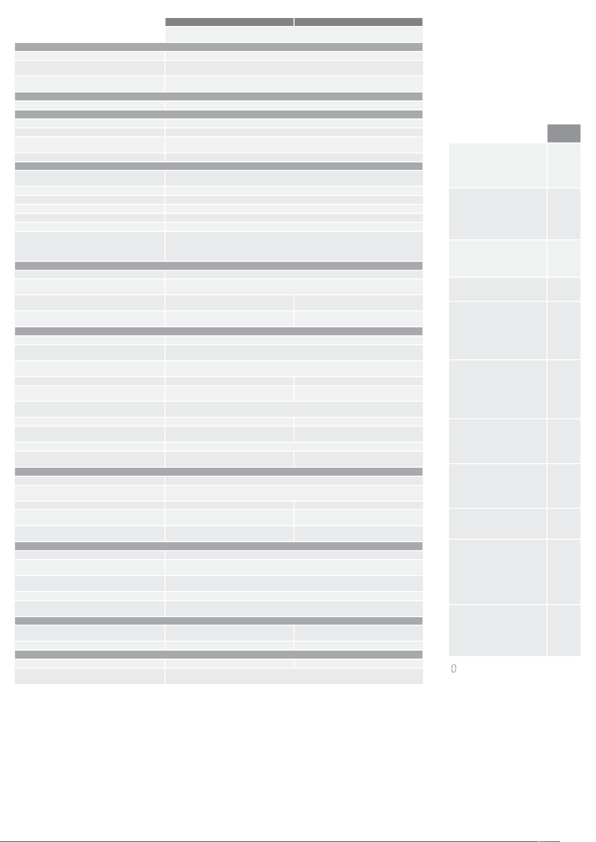
Technische Daten
Technical data
Normen Safety standards
Sicherheit Safety EN 6095 0- 1, UL 6 09 50 -1, UL 50 8
EMV
EMC
Schutzkleinspannung
Sa fet y ext r a- low vol tag e
Zulassungen Approvals
UL UL 60950 / UL 508
Umwelt Environment
Umgebungstemperatur Ambient temperature -10 °C ... +60 °C
Lagertemperatur Storage -25 °C ... +85 °C
Kühlart
cooling
zulässige Luftfeuchtigkeit Allowable humidity 5 ... 96 % relative Feuchte, keine Betauung zulässig 5 to 96 % relative humidity with no dew
Sicherheit und Schutz Safety and protection
Prüfspannung (Klemmen gegen Gehäuse)
HV test voltage (terminals to enclosure)
Bauart Construction gekapselt, für den Einbau im Schaltschrank enclosed for installation in switching cabinets
Schutzart Protection index IP 20 (nach EN 60529) IP 20 (to E N 60529)
Schutzkleinspannung Safety extra-low voltage EN 60950 (SELV) und EN 60204 (PELV) EN 60950 (SELV) und EN 60204 (P ELV)
Schutzklasse Safety class III
Verpolungsschutz Reverse connection protection ja yes
Parallelschaltbarkeit (Akkumodul)
Parallel operation
Eingang Input
Eingangsnennspannung Rated input voltage 24 Vd c
Eingangsspannungsbereich
Operating input voltage range
Stromaufnahme bei 24 Vdc (Leerlauf/Ladevorgang/max.)
Input current at 24 Vdc (standby/charging process/max.)
Anschlüsse: WAGO Multisteckersystem
Terminals: WAGO multi plug system
Ausgang Output
Ausgangsnennspannung Rated output voltage 24 Vdc
Ausgangsspannung (Normalbetrieb, Nennlast)
Operating output voltage (normal operation)
Ausgangsspannung (Pufferbetrieb, Nennlast)
Operating output voltage (buffer operation)
Ausgangsnennstrom Operating output current 10 A 20 A
Strombegrenzung mit zyklischer Abschaltung
Over current protection with hiccup mode
Fernabschaltung für NOT AUS des Pufferbetriebs
Remote power off (buffer operation)
Wirkungsgrad Efficiency typ. 95 % typ. 95 %
max. Verlustleistung Leerlauf/ Nennbetrieb)
max. Power loss idling / nominal load
Rückspeisefestigkeit Feedback voltage max. 35 Vdc
Anschlüsse: WAGO Multisteckersystem
Terminals: WAGO multi plug system
Speichermedium Storage medium
Nennspannung Rated voltage 24 Vdc
Ladeschlussspannung
Charging voltage upper level
Ladestrom Charging current max. 0,6 A max. 0.6 A max. 1,0 A max. 1.0 A
empfohlendes Speichermedium
recommended storage medium
Anschlüsse: WAGO Multisteckersystem
Terminals: WAGO multi plug system
Signalisierung Signaling
LED LED grün / gelb / rot green / yellow / red
potenzialfreier Kontakt (konfigurierbar)
Potential free signal contact (configurable)
aktive Schaltausgänge (konfigurierbar)
Active switched outputs (configurable)
Schnittstelle Interface RS-232
Anschlüsse: WAGO Multisteckersystem
Terminals: WAGO multi plug system
Sonstiges Various
Maße B x H x T*
Dimensions width x height x depth*
Gewicht Weight 0,8 kg 0.8 kg 1,2 kg 1.2 kg
Bestellnummern Order numbers
Standard Standard PVUA 24/24-10 PVUA 24/24-20
Anschlusstecker für Signalisierung, optional
connector for signaling, optional
*
Maße ohne Anschlussstecker, Tiefe T ab Oberkante Tragschiene.
* Dimensions withou t terminals, depth from upper edge of DIN rail.
** WAGO Serie 831: Mit Aderendhülse max. 6 mm². Bei feindrähtigen Leitern bitte geeigneten Spleißschutz verwenden.
** WAGO series 831: With ferrule max. 6 mm². Please use suitable anti-splaying method for fine-stranded conductors.
yes, max. 3 to increase the buffer time (Both control-lines should be connected to only one of the
PVUA 24/24-10 PVUA 24/24-20
Lade- und Kontrolleinheit für die Verwendung von Blei-Vlies-Batteriemodulen
ja, max. 3 zur Verlängerung der Pufferzeit (Beide Steuerleitungen sind nur an einem
0,1 A / 0,8 A / 10,8 A
0.1 A / 0.8 A / 10.8 A
Serie 231, max 2,5 mm
series 231, max 2.5 mm
Serie 231, max 2,5 mm
series 231, max. 2.5 mm
PVAF 24/1,2Ah PVA 24/3,2Ah,
PVA(F) 24/7Ah, PVA(F) 24/12 Ah
Serie 231, max 2,5 mm
series 231, max. 2.5 mm
Relaiskontak, Typ: Wechsler, Schaltleistung: 30 Vdc / 1A (240 Vac / 0,5 A)
40 x 127 x 163 mm 57 x 127 x 163 mm
Charge- and control unit for lead-acid batteries
EN 610 0 0- 6-2 und EN 610 00 -6- 3 (Fa ch gru nd n or m en )
EN 61000-6 -2 and EN 61000-6- 3 (generic standard)
EN 60950 (SELV) und EN 60204 (PELV)
EN 6095 0 (S ELV) an d EN 60 20 4 ( PE LV )
Selbstkühlung durch natürliche Konvektion bei vertikaler Einbaulage
typ. 11 ... 14 A typ. 22 ... 26 A
15 W / 20 W 15 W / 30 W
relay contact, type: switch over: 30 Vdc / 1A (240 Vac / 0,5 A)
AN (Natural air convection cooling)
500 Vdc
Batteriemodul anzuschließen)
battery module)
22 Vdc bis 29 Vdc
22 Vdc to 29 Vd c
2
2
typ. Uin - 1 Vdc
typ. Akkuspannung - 1 Vdc
typ. battery voltage - 1 Vdc
ja
yes
2
2
²
26 ... 29,5 Vdc (einstellbar oder temperaturgeführt)
26 ... 29.5 Vdc (adjustable or temperature controlled)
2
2
24 Vdc/max. 25 mA
Serie 733, max. 0,5 mm
series 733, max. 0.5 mm
PV-CON
0,1 A / 1,5 A / 21,5 A
0.1 A / 1.5 A / 21.5 A
Serie 831, max. 10 mm
serie 831, max. 10 mm
Serie 831, max. 10 mm
series 831, max. 10 mm
PVA(F) 24/7Ah,
PVA(F) 24/12 Ah
Serie 831, max. 10 mm
series 831, max. 10 mm
2
2
2 **
2 **
2 **
2 **
2 **
2 **
²
Fehler/Warnungen
Faults/warning
Folgende Störungen können von dem Modul detektiert werden und über die
Signalausgänge oder über die Schnittstelle ausgewert et werde n. Auch am Gerät selbst lässt sich eine
Fehlerdiagnose durch den integrierten Fehlermanager durchführen.
These faults or warnings can be detecte d by the
module , to be evaluated thr ough the signal output
interfac e. Also direc tly on the unit, faults can be
di ag nos ed wi th th e h el p o f th e fau lt mana ge r.
Anzeige
Display
Unterspannung am Eingang
(Uin too low)
Die Eingangsspannung ist unter einen
einstellbaren Grenzwert gesunken.
The input voltage dropped under the
set threshold
Unterspannung am Ausgang
(Uout too low)
Die Ausgangsspannung ist unter
einen einstellbaren Grenzwert
gesunken.
The output voltage dropped under
the set threshold
Überstrom (Iout too high)
Der Ausgangsstrom ist über einen
einstellbaren Grenzwert gestiegen.
The output current is higher than the
set threshold
Pufferbetrieb (buffer mode)
Das Modul ist im Pufferbetrieb.
The module is in buffer mode
Keine Temperatursteuerung
möglich
(no temperature tracking)
Die Temperatur im Akkumodul kann
nicht gemessen werden.
The measurement of the temperature in the battery module is not
possible
Kein Batteriebetrieb möglich
(buffer mode not possible)
Keine Batteriespannung gemessen
oder NOT-AUS-Brücke für Fernabschaltung ist unterbrochen.
No battery voltage measured or
the emergency stop bridge for the
remote switch off is open.
Ausgang abgeschaltet
(fault current mode active)
Der Ausgang ist aufgrund eines
Überstromes abgeschaltet.
The output has been switched off due
to over-current
Batterie kleiner 85% aufgeladen
(battery charge < 85%)
Das angeschlossene Batteriemodul
ist weniger als 85 % geladen.
The battery is charged to less than
85% of its capacity.
Gerätefehler (hardware fault)
Der interne Geräte-Selbsttest ist
fehlgeschlagen.
The internal self test failed
Batteriespannung gering
(battery voltage very low)
Die Batteriespannung ist im Pufferbetrieb auf einen kritischen Wert
gesunken. (Tiefentladespannung bald
erreicht)
The battery voltage dropped under
a critical value during buffer mode.
(Deep discharge almost reached)
Akkutausch empfohlen
(accu change recommended)
Die Restlebenserwartung der
Akkumulatoren ist zu gering. Ein
Austa usch wi rd empfohlen.
Batt ery li fe expect ancy is t oo low.
An exchange is recommended.
Segment blink t segment blinks
$!!
%!!
!$!
!%!
!!$
!!%
&!!
'!!
!&!
!'!
!!&
 Loading...