

Block PVRE User manual [ml]
Sicherheitsmaßnahmen vor der Installation
Das Betriebsmitt el ist vor unzulässiger Beanspruchung zu schüt zen.
Insbesondere dürfe n bei Transport und Handhabung keine Bauelemente verboge n und/oder Isolatio nsabs tänd e verände rt werden. Die
Berüh rung elek tri scher Baueleme nte und Kont akt e ist zu vermeide n.
Betr iebsm itt el immer im spannun gsfr eien Zustand mont ieren und
verdr ahten. Die Produktbeschr eibung und die technis chen Hinweise in
unser em Hauptkatal og sowie die Aufs chri ft en am Betriebsmit tel und
auf dem Typenschild sind zu beacht en.
Installation
Die Installation ist entsp rech end den örtl ichen Gegebenheit en,
einschlägig en Vorschrif ten (z. B. VDE 0100), nationalen Unf allverhütungsvorschrifte n (z. B. UVV-VBG4 bzw. BGV A2) und den anerkannt en
Regeln der Technik durchzu führ en. Dies es elekt risc he Betriebsmitt el
ist eine Kompo nent e, die zum Einbau in elekt risc he Anlage n oder
Maschi nen best immt ist und erfüllt die Anforder ungen der Niedersp annungsr icht linie (73 /23/ EWG). Der geforder te Mindestabstand vom
10 mm zu benachbarte n Teilen ist unbeding t einzuhalten , um die Kühlung nicht zu behin dern ! Bei Einbau in Maschin en ist die Aufnahme des
bestimmung sgemäßen Betr iebes solange untersag t, bis fest gest ellt
wurde, dass die Maschine den Bestimm ungen der Masc hinen richtlini e
(89/392/E WG) ent spricht; EN 60204 ist zu beach ten. Die Aufnahme
des bestimmungsgemäßen Betriebes ist nur bei Einhaltun g der EMVRicht linie (89/336/ EWG ) erlaubt . Die Einhaltung der durch die EMVGeset zgebung gefo rder ten Gre nzwert e liegt in der Verantw ort ung des
Herstellers der Anlage oder Maschine.
Installation
Anschluss
PVRE
BLOCK Transformatoren-Elektronik GmbH & Co. KG
Max-Planck-Straße 36–46
27283 Verden
Germany
Phone +49 4231 678-0
Fax +49 4231 678-177
info@block-trafo.de
www.block-trafo.de
www.pv400.de
Technische Änderungen vorbehalten.
Subject to change.
KAPVRE 06.07.PDF.0 Printed in Germany ©G.V.K. 3rd unit Lüneburg
Redundanzmodul mit 2 Eingängen
für 24-V-Umgebung
Redundant module for 24 V supply
with two inputs
1
2
3
1
LEDs : Die grüne LED (a) leuchtet , sofern U
out
größer als ca. 19,8 V
ist. Die gelb e LED (b) leucht et, sofern Uin2 größer als ca. 19,8 V ist.
Die gelbe LED (c) leuchte t, sofern Uin1 größer als ca. 19,8 V ist.
Eingä nge
: IN 1, IN 2
Pote ntia lfre ier Wechs elkon takt
: 1, 2, 4
Ausga ng
: OUT
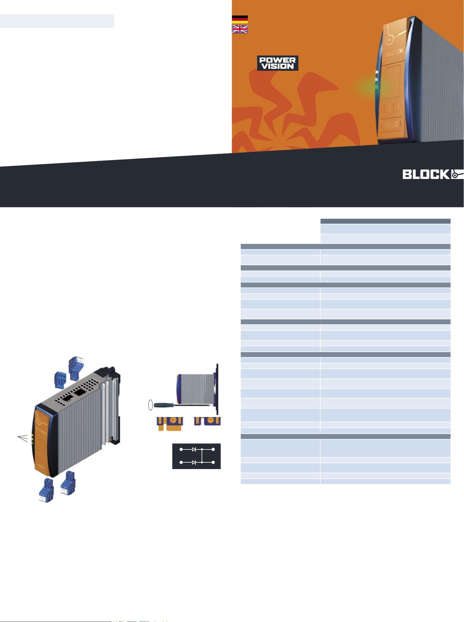
Mont age: PVR E mit geöff net er Schlie ßnocke (6a) im recht en
Winkel auf die Tragschiene TS35 setze n. Befe stigung mit Schrau bendr eher im Uhrzeigersinn schließen (6b).
Downl oad der ausfü hlich en Betriebsanleit ung unte r: www. pv400 .de
Downl oad the compl ete user manual at www.pv400.d e
a
b
c
6
Technische Daten
Technical details
PVRE 2 4/24 -20
Redun danzm odul mit 2 Eingängen für 24-V-Umgebung ,
für TS35-Schien enmon tage ode r Schraubbesf esti gung
Redun dant modu le for 24 V supply with two input s for mounti ng
on DIN 35 mm rails or screw mounting
Norme n Safe ty stand ards
Sicherheit Safety EN 60950, UL 60950, UL 508 EN 60950, UL 60950, UL 508
EMV
EMC
EN 61000-6 -2 und EN 61000-6-3 (Fach grund norme n)
EN 61000-6 -2 and EN 61000-6-3 (gene ric standard)
Zulas sunge n Approvals
UL (vorbereit et) UL (Pending) UL 60950 (CSA C22.2 /No.60950 ) UL 60950 (CS A C22.2/N o.60950)
UL (vorbereit et) UL (Pending) UL 508 (CSA C22.2/ No.14- 95) UL 508 (CSA C22.2/No.14-95 )
Umwel t Environme nt
Umgebu ngst emperatur Ambient temperature –10° C bis +60° C –10° C to +60° C
Lager temperatur Storage –25° C bis +85° C –25° C to +85° C
Kühlar t
Cooling
Selbs tkühlung durch natürliche Konve ktion bei vertikaler Einb aulage
AN (Natu ral air convectio n cooling)
Zulässige Luftfeuchtigkeit
Allow able humid ity
30 bis 85% relativ e Feucht e, keine Bet auung zulä ssig
30 to 85% relativ e humidit y with no dew
Siche rheit und Sch utz Safet y and protec tion
Prüf spannung HV test voltag e
500 Vdc (Klemmen zum Gehäuse) 500 Vdc (terminals to enclosure)
Bauar t
Const ruction
gekapselt , für den Einbau im Schalt schrank
enclo sed for installat ion in switc hing cabi nets
Schut zar t Protection inde x IP 20 (nach EN 60529) IP 20 (to EN 60529)
Schut zkl asse Safet y class III III
Elek trisc he Daten Electri cal rati ngs
Bemes sungsspannung Designated voltage 24 Vdc 24 Vdc
Bereich Voltage range 18 Vdc bis 30 Vdc 18 Vdc to 30 Vdc
Spannu ng (max. zulässig )
Voltage (max. allowable)
39 V (kurzzeitig ) 39 V
(short ter m)
Ansch lüsse : WAGO Multistecker syst em
Terminals : WAGO multi plug system
WAGO Serie 831, max 10,0 mm² (+), WAGO Serie 231, max 2,5 mm² (-, Relais)
WAGO series 831, max 10,0 mm² (+), WAGO series 231, max 2,5 mm² (-, relais )
Nennstrom je Eingang und Ausgang
Designated current per input and output
20 A
20 A
Maximalstrom je Eingang und Ausgang
Max. current per input and output
30 A (40 A für 5 Sek. Real Power Boost)
30 A (40 A for 5 sec. Real Power Boost )
Parallelbe trieb
Parallel opera tion
Ja, wenn der Maximalstrom am Ausgang nich t den maximal
zuläss igen Wert überste igt
Yes as long as the output current does not exceed the max. allowable
Verpol schutz Reverse connect ion prot ect ion ja yes
Wirkungsgr ad Effici ency >97 % >97 %
Sons tiges Variou s
Befe stig ung
Mount ing
Tragschienenmontage (DIN EN 60715:2001-09) mit zwei
Montagemöglichkeit en oder Direk tverschraubu ng
rail mount ing (DIN EN 60715:2001-09) with two possible varie ties
or direct screw mount ing
Verpac kung Packing Einze lver packung im Karton single packed in carton
Maße B x H x T (ohne Anschlussste cker)
Dimensions width x height x depth
40 x 127 x 163 mm
40 x 127 x 163 mm
Gewic ht Weight 0,8 kg 0,8 kg
Best ellnu mmer Order no.
PVRE 24/24- 20
TS35
5
a b
ü
ü
6
5
Funktionen und Anwendungsbereiche
Diese Einb aukomponen te ist zum Einsat z in 24-V-Net zen bei indus triellen Verbrauchern der Infor mati onst echnik (IT) , Automatisierungstechnik, des Anla genbaus, der Verfa hrenstec hnik und der Steuerung stechnik geeign et. Das Redundanzmodul PVR E dient der Entko pplung
mehre rer Net zte ile zum Aufbau einer ausfallsicheren Stromversorgung. Wenn ein Netzteilausgang im Fehler fall kurzgesc hlossen ist, arbeit et ein zweit es Netzteil in diesem Falle nicht auf diesen Kurzschluss,
sondern versor gt weit erhin die Last. Ein potential fre ier Melde kont akt
(Relaiswe chsle r) fällt ab, sobal d eine der beiden Eingangssp annungen
unter die Power Good Schwe lle sinkt.
www.pv400.de
KAPVRE 2007•06
4
2
3
block-trafo.de
Connection
Safety measures before installation
This equipment is to be protected against improper use. Comp onents
are not to be bent or isolation spacing chan ged, espe cially throug h
handling and transpo rt. The con tac t with elec tric al compon ents and
terminals is to be avoided. Always disc onnect the equipment from the
mains suppl y, befor e commenc ing installat ion or wiring . The produc t
descr ipti on, technical informa tion in our main catalogue and the marking on the equipm ent rati ngs plate are to be obser ved.
Installation
Installat ion must be carried out according to the prevailing local
condi tions and safety reg ulations (e.g. VDE 0100) natio nal accid ent
prevention regulations (e .g. UVV- VBG4 or BGV A2) and the generally
accepted rules of technology. This equ ipmen t is a compo nent desi gned
for installat ion into electrical syst ems and machin es, and fulf ils the
requi reme nts of the low volt age guidel ines (73/ 23/E WG) . The requir ed
min spacing of 10 mm to neighbouring componen ts must be observed
to guarantee the requ ired coo ling. Whe n installed into machinery, the
normal ope rati on is forbidd en until it is deter mined tha t the machine
fulf ils the requireme nts of the machinery guideline s (89/392 /EW G).
EN 60204 must be observ ed. The EMC requirements must be fulfille d
befo re operation is commenced. The observance of the requi red limitations for the EMC legi slation is the responsibili ty of the manufactu rer of
the installat ion or machine ry.
Installation
T
To reduce the risk of mista king the term inals , the suppli ed
termi nals mus t be used.
T
Um Verwech slung en mit ander en Anschl üsse n zu vermeide n, verwen den Sie aussc hlie ßlich die mit gelie fer ten
Stec ker.
Function and area of application
This component is for use with industrial loads in infor mation technolog y system s (IT) wit h a 24 V line supply, automotiv e techno logy,
system technology, process engineer ing and contr ol technolog y. This
redundant modul e PVRE serves to de-couple mult iple unit s to ensure
a fault free powe r supply syst em. In the case of a short circuit in one
power supp ly, a second unit will take over, supplyin g power to the load.
A potent ial free rel ay contact will swit ch as soon as one of the input
volt ages drop s below the Power Good set level.
4
LEDs : The green LED (a) lights as soon as the output volt age is
larger than 19,8 V. The yellow LED (b) light s as soon as Uin2 is
larger than 19,8 V. The yellow LED (c) light s as soon as Uin1 is
larger than 19,8 V.
Input s
: IN 1, IN 2
Pote ntia l free switc h contac t
: 1, 2, 4
Outp ut
: OUT
Mont age: Plac e the PVRE with ope ned cam lock (6a) in a 90°
angle on the DIN 35 mm rail and clos e the cam lock in a clockwise
direc tion with a screwdr iver (6b ).
IN 1
IN 2
prinz ipiel ler Aufb au
build up in principle
OUT
1
2
3
65
4

system-modulessemistabilisedstabilised
stabilised
semistabilised
system-modules
PVSE PVSB PVSL PVE PVB PVL PVU PVR PVF
Stabilisierte Stromversorgung, Economy
Stabilised economic
power supply
PVSE 400 /24-1 0
PVSE 400 /24-2 0
PVSE 400 /24- 40
Stabilisierte Stromversorgung, Basic
mit integrierter
Kontrolleinheit
Stabilised basic power
supply with
integrated
control module
PVSB 400 /24-1 0
PVSB 400 /24-2 0
PVSB 400 /24- 40
Stabilisierte Stromversorgung mit
integrierter
Kontrolleinheit und
Netzeingangsüberwachung
Stabilised power
supply with integrated
control module and
line monitor
PVSL 400 /24-1 0
PVSL 400 /24-2 0
PVSL 400 /24- 40
Semistabilisierte
Stromversorgung,
Economy
Semi stabilised
economic power
supply
PVE 400/2 4-10
PVE 400/2 4-20
PVE 400/2 4-4 0
Semistabilisierte
Stromversorgung,
Basic mit integrierter
Kontrolleinheit
Semi stabilised basic
power supply with
integrated control
module
PVB 400/2 4-10
PVB 400/2 4-20
PVB 400/2 4-4 0
Semistabilisierte
Stromversorgung mit
integrierter
Kontrolleinheit und
Netzeingangsüberwachung
Semi stabilised power
supply with integrated
control module and
line monitor
PVL 400/2 4-10
PVL 400/2 4-20
PVL 400/2 4-4 0
PVUA 24/2 4-10
PVUC 24/2 4-10
PVA 24/3,2 Ah
PVA 24/7 Ah
Redundanzmodul mit
2 Eingängen
für
24-V-Umgebung
Redundant module for
24 V supply with two
inputs
PVRE 24/ 24-2 0
PVRB 24/ 24-2 0
Elektronischer
Schutzschalter mit
4 Kanälen für 24-VUmgebung
Electronic fuse unit of
up to four channels
for 24 V
PVFE 24/ 24-4 0
PVFB 24/ 24-3 2
PVUA Unterbre-
chungsfreie Stromversorgung
Uninterruptible power
supply
PVUC Kapazitives
Puffermodul
Capacitive buffer
module
PVA Akku-Block
Akkumulator
 Loading...