

Block PVA 24/3.2 Ah User guide [ml]
Sicherheitsmaßnahmen vor der Installation
Das Betriebsmitt el ist vor unzulässiger Beanspruchung zu schüt zen.
Insbesondere dürfe n bei Transport und Handhabung keine Bauelemente verboge n und/oder Isolatio nsabs tänd e verände rt werden. Die
Berüh rung elek tri scher Baueleme nte und Kont akt e ist zu vermeide n.
Betr iebsm itt el immer im spannun gsfr eien Zustand mont ieren und
verdr ahten. Die Produktbeschr eibung und die technis chen Hinweise in
unser em Hauptkatal og sowie die Aufs chri ft en am Betriebsmit tel und
auf dem Typenschild sind zu beacht en.
Installation
Die Installation ist entsp rech end den örtl ichen Gegebenheit en,
einschlägig en Vorschrif ten (z. B. VDE 0100), nationalen Unf allverhütungsvorschrifte n (z. B. UVV-VBG4 bzw. BGV A2) und den anerkannt en
Regeln der Technik durchzu führ en. Dies es elekt risc he Betriebsmitt el
ist eine Kompo nent e, die zum Einbau in elekt risc he Anlage n oder
Maschi nen best immt ist und erfüllt die Anforder ungen der Niedersp annungsr icht linie (73 /23/ EWG). Der geforder te Mindestabstand von
10 mm zu benachbarte n Teilen ist unbeding t einzuhalten , um die Kühlung nicht zu behin dern ! Bei Einbau in Maschin en ist die Aufnahme des
bestimmung sgemäßen Betr iebes solange untersag t, bis fest gest ellt
wurde, dass die Maschine den Bestimm ungen der Masc hinen richtlini e
(89/392/E WG) ent spricht; EN 60204 ist zu beach ten. Die Aufnahme
des bestimmungsgemäßen Betriebes ist nur bei Einhaltun g der EMVRicht linie (89/336/ EWG ) erlaubt . Die Einhaltung der durch die EMVGeset zgebung gefo rder ten Gre nzwert e liegt in der Verantw ort ung des
Herstellers der Anlage oder Maschine.
Installation
Anschluss
BLOCK Transformatoren-Elektronik GmbH & Co. KG
Max-Planck-Straße 36–46
27283 Verden
Germany
Phone +49 4231 678-0
Fax +49 4231 678-177
info@block-trafo.de
www.block-trafo.de
www.pv400.de
Technische Änderungen vorbehalten.
Subject to change.
KAPVA 08.07.PDF.0 Printed in Germany ©G.V.K. 3rd unit Lüneburg
1
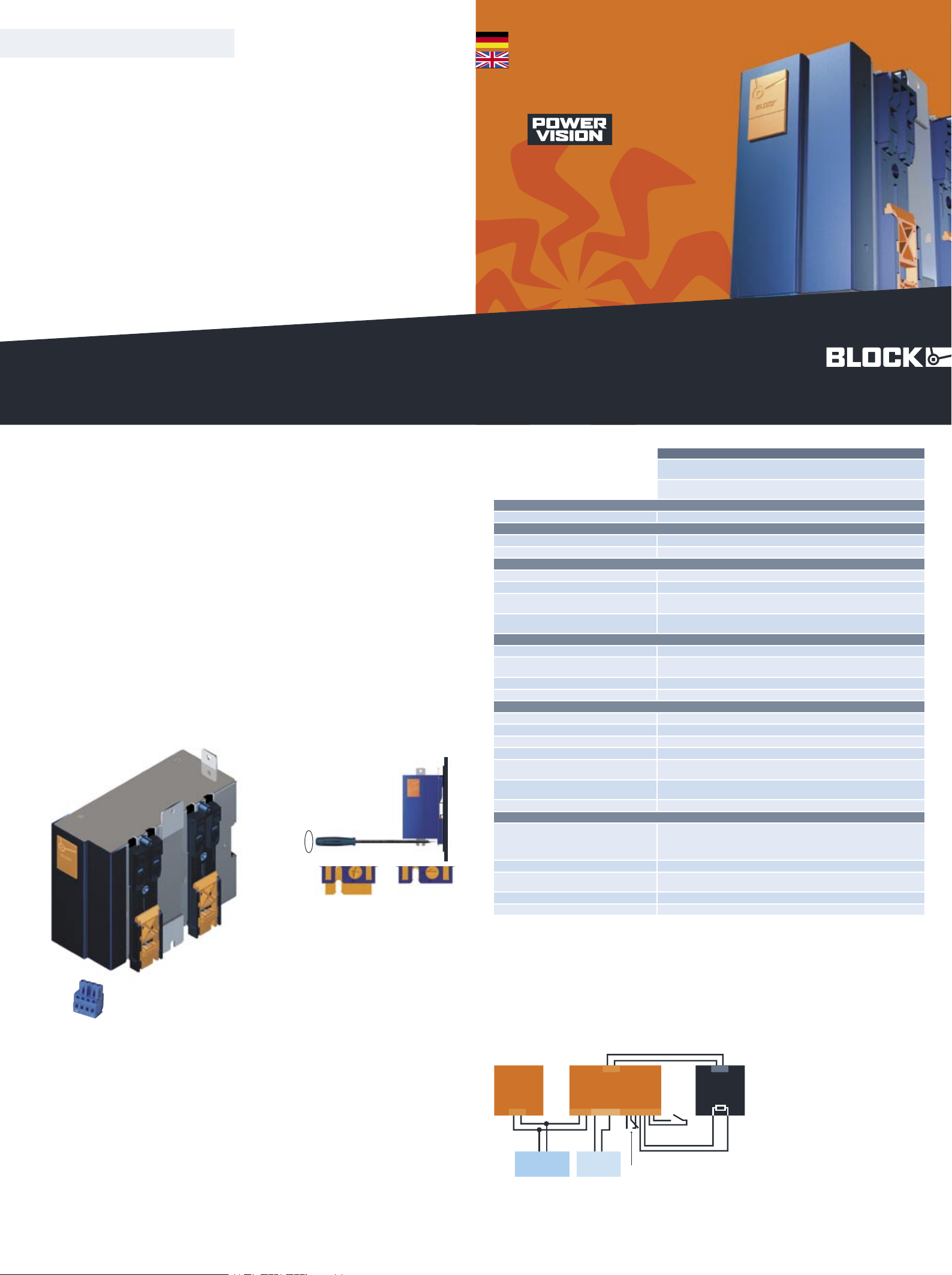
Ansch luss : siehe Ansch lussplan rechts.
Mont age:
PVA mit geöff neter Schließnock e (2a) im rechten
Winkel auf die Tragschiene TS35 setze n. Befe stigung mit Schrau bendr eher im Uhrzeigersinn schließen (2b). Für diese Befestigungsvarian te bedar f es im Schaltsc hrank mehr Platz, da das Gerät
längs eingebaut wir d.
Montage mit der Befes tigungsmöglichkeit zwischen den beiden
PV-Halter ungen. Für diese Befe stigungsvariante bedar f es im
Schal tsch rank mehr Platz, da das Gerät längs eingebaut wird.
Plat zspar ende Montage durc h die beiden Laschen an der Rückseit e.
Downl oad der ausfü hrlic hen Betriebs anlei tung unt er: www.pv400.de
Downl oad the compl ete user manual at www.pv400.d e
2
Technische Daten
Technical details
PVA 24/3,2 Ah
Akku- Bloc k für die Unterbrechungsf reie St romversor gung PVUA
für TS35-Schien enmon tage ode r Schraubbesf esti gung
Accum ulat or block for the unint erruptible power supply PVUA
for mount ing on DIN 35 mm rails or screw mounting.
Norme n Safe ty stand ards
Sicherheit Safety Akkumulat oren VdS geprü ft accumulat or is teste d to VdS
Zulas sunge n Approvals
UL (vorbereit et) UL (Pending) UL 60950 (CSA C22.2 /No.60950 ) UL 60950 (CS A C22.2/N o.60950)
UL (vorbereit et) UL (Pending) UL 508 (CSA C22.2/ No.14- 95) UL 508 (CSA C22.2/No.14-95 )
Umwel t Environme nt
Umgebu ngst emperatur Ambient temperature –10° C bis +40° C –10° C to +40° C
Lager temperatur Storage –25° C bis +50° C –25° C to +50° C
Kühlar t
Cooling
Selbs tkühlung durch natürliche Konve ktion bei vertikaler Einb aulage
AN (Natu ral air convectio n cooling)
Zulässige Luftfeuchtigkeit
Allow able humid ity
30 bis 85% relativ e Feucht e, keine Bet auung zulä ssig
30 to 85% relativ e humidit y with no dew
Siche rheit und Sch utz Safet y and protec tion
Prüf spannung HV test voltag e
500 Vdc (Klemmen zum Gehäuse) 500 Vdc (terminals to enclosure)
Bauar t
Const ruction
gekapselt , für den Einbau im Schalt schrank
enclo sed for installat ion in switc hing cabi nets
Schut zar t Protection inde x IP 20 (nach EN 60529) IP 20 (to EN 60529)
Schut zkl asse Safet y class III III
Elek trisc he Daten Electri cal rati ngs
Kapazität Capac ity 24 Vdc / 3,2 Ah 24 Vdc / 3,2 Ah
Ladespannun g Charging volt age 26 bis 29,5 Vdc 26 to 29,5 Vdc
Kurzs chlus sschu tz Short-cir cuit pro tec tion durch int erne 15 A FKS through inte rnal 15 A FKS
Temperat urse nsor Temperature sensor K164, 4K7 K164, 4K7
Temperat urge führ e Akkula despa nnung
Temperat ure cont rolled charging curre nt
mit internem NTC (Type K164 4K7 ) 27,5 Vdc bei 25° C mit PVUA 24/24-10
with an inte grat ed NTC (type K1644K 7) 27,5Vdc at 25° C with the PVUA 24/24-10
Ansch lüsse : WAGO Multistecker syst em
Terminals : WAGO multi plug system
WAGO Serie 231, max 2,5 mm² , 4-pol. Belegung: +,NTC, NTC, –
WAGO series 231, max 2,5 mm² , 4 pole conf iguration: +,NTC, NTC , –
Laststrom Load current max. 10 A max. 10 A
Sons tiges Variou s
Befe stig ung
Mount ing
Tragschienenmontage (DIN EN 60715:2001-09) mit drei
Montagemöglichkeit en oder Direk tverschraubu ng
rail mount ing (DIN EN 60715:2001-09) with three* possible vari etie s
or direct screw mount ing
Verpac kung Packing Einze lver packung im Karton single packed in carton
Maße B x H x T (ohne Anschlussste cker)
Dimensions width x height x depth
76 x 167 x 174 mm
76 x 167 x 174 mm
Gewic ht Weight 4,2 kg 4,2 kg
Best ellnu mmer Order no.
PVA 24/3,2 Ah
TS35
a b
ü
ü
2
Funktionen und Anwendungsbereiche
Das Akku- Modul PVA 24/3,2 Ah wird in Verbindung mit dem Akku manageme ntsyste m PVUA 24/24/10 zur Erzeugung einer unterbrechungs fre ien 24 Vdc Systemsp annung verwendet.
1
Connection
Safety measures before installation
This equipment is to be protected against improper use. Comp onents
are not to be bent or isolation spacing chan ged, espe cially throug h
handling and transpo rt. The con tac t with elec tric al compon ents and
terminals is to be avoided. Always disc onnect the equipment from the
mains suppl y, befor e commenc ing installat ion or wiring . The produc t
descr ipti on, technical informa tion in our main catalogue and the marking on the equipm ent rati ngs plate are to be obser ved.
Installation
Installat ion must be carried out according to the prevailing local
condi tions and safety reg ulations (e.g. VDE 0100) natio nal accid ent
prevention regulations (e .g. UVV- VBG4 or BGV A2) and the generally
accepted rules of technology. This equ ipmen t is a compo nent desi gned
for installat ion into electrical syst ems and machin es, and fulf ils the
requi reme nts of the low volt age guidel ines (73/ 23/E WG) . The requir ed
min spacing of 10 mm to neighbouring componen ts must be observed
to guarantee the requ ired coo ling. Whe n installed into machinery, the
normal ope rati on is forbidd en until it is deter mined tha t the machine
fulf ils the requireme nts of the machinery guideline s (89/392 /EW G).
EN 60204 must be observ ed. The EMC requirements must be fulfille d
befo re operation is commenced. The observance of the requi red limitations for the EMC legi slation is the responsibili ty of the manufactu rer of
the installat ion or machine ry.
Installation
T
To reduce the risk of mista king the term inals , the suppli ed
termi nals mus t be used.
T
Um Verwech slung en mit ander en Anschl üsse n zu vermeide n, verwen den Sie aussc hlie ßlich die mit gelie fer ten
Stec ker.
block-trafo.de
PVA
Akku-Block für PVUA
Akkumulator-Block for the PVUA
Function and area of application
The accumulator module PVA 24/3,2 toge ther wit h the accumul ator
management syst em PVUA 24/24/10, are used to create an unint erruptible 24 V power supply.
3
4
3
2
2
4
1
Conne ctio ns: see conne cti on diagram on the right.
Mount ing:
Place the PVA with opened cam lock (2a) in a 90° angle on the DIN
rail and close the cam lock in a clockw ise dire ction with a screwdrive r (2b) For this method of mountin g, more space in the wiring
cabinet is required as the module needs to be placed lengthw ise
on the DIN rail.
Using the scre w mounting lugs in betwee n the cam lock device also
requi res more space due to the lengthw ise position of the module
on the DIN rail.
A space saving moun ting variatio n using the screw moun ting lugs ,
on the rear of the PVA.
2
3
4
PVUA
Power
Supply
ACC
+ –
IN
– +
�
OUT
1
7
– – + +
OU
T
+ –
Accu
PVA
K 164/4K7
SIGNAL
disconnection
output
temperature-tracking with external NTC
potential free switch contact
• • • • • • •
Unbuffered
Load
Buffered
Load
– +
Anschlussplan
Connecting diagram
www.pv400.de
KAPVA 2007•08

system-modulessemistabilisedstabilised
stabilised
semistabilised
system-modules
PVSE PVSB PVSL PVE PVB PVL PVU PVR PVF
Stabilisierte Stromversorgung, Economy
Stabilised economic
power supply
PVSE 400 /24-1 0
PVSE 400 /24-2 0
PVSE 400 /24- 40
Stabilisierte Stromversorgung, Basic
mit integrierter
Kontrolleinheit
Stabilised basic power
supply with
integrated
control module
PVSB 400 /24-1 0
PVSB 400 /24-2 0
PVSB 400 /24- 40
Stabilisierte Stromversorgung mit
integrierter
Kontrolleinheit und
Netzeingangsüberwachung
Stabilised power
supply with integrated
control module and
line monitor
PVSL 400 /24-1 0
PVSL 400 /24-2 0
PVSL 400 /24- 40
Semistabilisierte
Stromversorgung,
Economy
Semi stabilised
economic power
supply
PVE 400/2 4-10
PVE 400/2 4-20
PVE 400/2 4-4 0
Semistabilisierte
Stromversorgung,
Basic mit integrierter
Kontrolleinheit
Semi stabilised basic
power supply with
integrated control
module
PVB 400/2 4-10
PVB 400/2 4-20
PVB 400/2 4-4 0
Semistabilisierte
Stromversorgung mit
integrierter
Kontrolleinheit und
Netzeingangsüberwachung
Semi stabilised power
supply with integrated
control module and
line monitor
PVL 400/2 4-10
PVL 400/2 4-20
PVL 400/2 4-4 0
PVUA 24/2 4-10
PVUC 24/2 4-10
PVA 24/3,2 Ah
PVA 24/7 Ah
Redundanzmodul mit
2 Eingängen
für
24-V-Umgebung
Redundancy module
for 24 V supply with
two inputs
PVRE 24/ 24-2 0
PVRB 24/ 24-2 0
Elektronischer
Schutzschalter mit
4 Kanälen für 24-VUmgebung
Electronic fuse unit of
up to four channels
for 24 V
PVFE 24/ 24-2 4
PVFE 24/ 24-4 0
PVFB 24/ 24-3 2
PVUA Unterbre-
chungsfreie Stromversorgung
Uninterruptible power
supply
PVUC Kapazitives
Puffermodul
Capacitive buffer
module
PVA Akku-Block
Akkumulator
 Loading...