

Block PEL230 User Manual
PEL 230
Primär getaktete Gleichstromversorgung
Primary switched mode Power supply
deutsch / english
block.eu
BLOCK Transformatoren-Elektronik GmbH
Max-Planck-Straße 36-46 . 27283 Verden, Germany
info@block.eu . block.eu
PEL 230 2015•08
block.eu
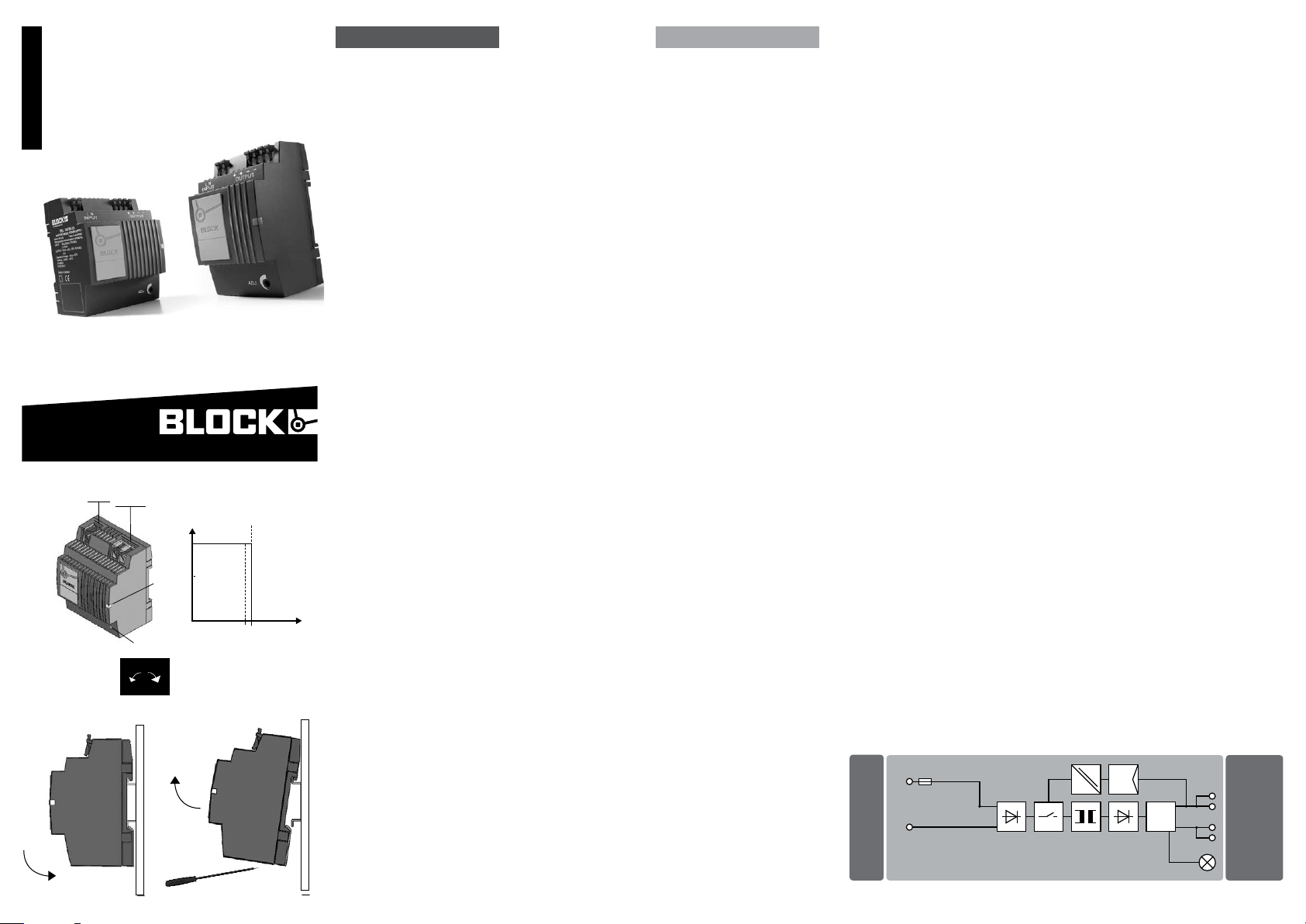
Eingang
5
3
input
L N
Ausgang
output
+ + – –
4
Ausgangskennlinie (U/I Kennlinie)
Output Characteristic (U/I Charakteristic)
U
(V)
out
1
IN
1,1 x I
2
U
out
+–
N
6
Fig. 1
deutsch english
Installation
Sicherheitsmaßnahmen vor der Installation
Das Betriebsmittel ist vor unzulässiger Beanspruchung zu
schützen. Insbesondere dürfen bei Transport und Handhabung
keine Bauelemente verbogen und/oder Isolationsabstände
verändert werden. Die Berührung elektrischer Bauelemente
und Kontak te ist zu vermeiden. Das Betriebsmittel immer im
sp a nnu n gsfrei e n Zustan d montie r e n und ve r d raht e n . Die Produktbeschreibung und die technischen Hinweise in unserem
Hauptkatalog sowie die Aufschriften am Betriebsmittel und
au f de m Typens c hild si nd zu be a chten.
Installation
Die Installation ist entsprechend den örtlichen Gegebenheiten,
einschlägigen Vorschriften (z. B. VDE 0100), nationalen
Unfallverhütungsvorschriften (z. B. UVV-VBG4 bzw. BGV
A3) und den anerkannten Regeln der Technik durchzuführen.
Dieses elektrische Betriebsmittel ist eine Komponente, die
zum Einbau in elektrische Anlagen oder Maschinen bestimmt
ist und erfüllt die Anforderungen der Niederspannungsrichtlinie (2014/30/EU). Der geforderte Mindestabstand zu
benachbarten Teilen ist einzuhalt en, um die Kühlung nicht
zu behindern! Bei Einbau in Maschinen ist die Aufnahme des
bestimmungsgemäßen Betriebes solange untersagt, bis
festgest ellt wurde, dass die Maschine den Bestimmungen
der Maschinenrichtlinie (2014/30/EU) entspricht. EN 60204
ist zu beachten. Die Aufnahme des bestimmungsgemäßen
Betriebes ist nur bei Einhaltung der EMV-Richtlinie (2014/30/
EU) erlaubt. Die Einhaltung der durch die EMV-Gesetzgebung
geforderten Grenzwerte liegt in der Verantwortung des Herstellers der Anlage oder Maschine.
Betriebsanzeige: Die gr ü ne LED
1
le u chtet, sofe r n die Aus gang s span nung vorhanden ist.
Ausgangsspannung: Die Au s-
2
gangsspannung kann mit einem
Schraubendreher verändert werden.
Drehung im Uhrzeigersinn erhöht die
Ausgangsspannung. Drehung gegen
den Uhrzeigersinn verringert die
Ausgangsspannung.
(A)
I
out
Eingang
3
Ausgang
4
Montage: Setzen Sie das Gerät mit
5
de r Tragsc h i enen f ü hrun g an die Ob e r ka n t e der Trag s chie n e an und ra sten
Si e es nach un t e n ein.
Demontage: Ziehen Sie den
6
Schnappriegel mit Hilfe eines
Schraubendrehers auf und hängen
Sie das Gerät an der Unterkante der
Tragschiene aus.
Installation
Safety measures before installation
This equipment is to be protected against improper use.
Components are not to be bent or isolation spacing changed,
especially through handling and transport. The contact with
electrical components and terminals is to be avoided. Always
disconnect the equipment from the mains supply, before
commencing installation or wiring. The product description,
technical information in our main catalogue and the marking
on th e equip m ent rat i n gs pl a t e are to be obs e r ved.
Installation
Installation must be carried out according to the prevailing
local conditions and safety regulations (e.g. VDE 0100)
national accident prevention regulations (e.g. UVV-VBG4 or
BGV A3) and the generally accepted rules of technology. This
eq u ipme n t is a comp o nent de s igne d fo r inst a l latio n into ele c trical systems and machines, and fulfils the requirements of
the low voltage guidelines (2014/30/EU).
The required minimum spacing to neighbouring components must be observed to guarantee the required cooling.
When installed into machinery, the normal operation is
forbidden until it is determined that the machine fulfils
the re q uire m e nts of th e mac h i nery gu idel i nes (20 14/ 30/
EU). EN 60204 must be observed. The EMC requirements
(2 014 / 30/ E U ) must be fu l f ille d be f ore ope r a t ion is co m menced. The observance of the required limitations for the
EMC legislation is the responsibility of the manufacturer of
the install a t ion or machin e r y.
Power indicator: The green LED
1
lights as soon as the output voltage
is present.
Output voltage: The output voltage
2
ca n be altered us ing a sc r e wdriv e r.
Tur n ing th e adjus t m ent scr e w clockwi s e raise s th e outpu t vo ltage . Tur ni n g the ad j ustme n t screw an t i cloc kwi s e re duc e th e output vo l t age.
Input
3
Output
4
Mounting: Place the device with the
5
DIN rail guide on the upper edge of the
DIN rail, and snap it in with a
downward motion.
Removing: Pull the snap lever open
6
with the aid of a screwdriver and slide
the device out at the lower edge of the
DIN rail.
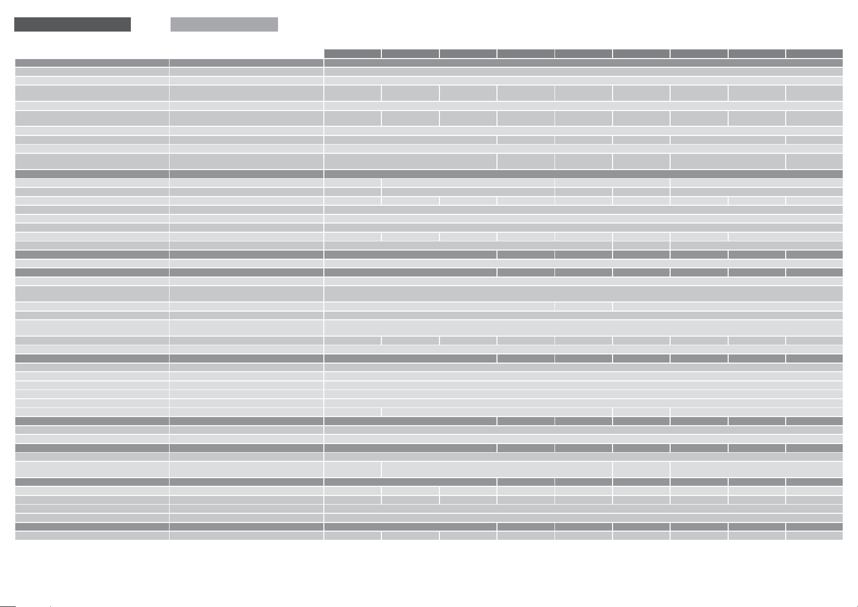
Fu nk t i onsscha l t b ild für PEL 23 0
Fu n c t i onal dia gram for PEL 23 0
L (–)
N (+)*
* Zweiphasenbetrieb nur möglich, sofern die maximale Eingangsspannung von 264 Vac nicht überschritten wird.
* Two phase operation only possible, if input voltage under 264 Vac.
Stand-by
–
–
+
+
LED (Green)
deutsch english
Technische Daten Technical data
P E L 23 0/ 5- 5 , 5 P E L 23 0/ 1 2 - 2 PEL 230/12-4 PEL 230/12-6,5 PEL 230/18-1, 1 PEL 230/18-2,5 PEL 230/24 -1,3 PE L 23 0/ 24- 2, 5 PEL 230/24-4
Eingangsdaten Input data
Eingangsnennspannung Rated input voltage 10 0 - 24 0 Vac
Eingangsspannungsbereich Input voltage range 85 - 264 Va c (1 2 0 - 37 3 Vd c)
Eingangsspannungsderating Input voltage derating -
ma x . 1 ,5 A (<1 0 0
Vac)
ma x . 3,5 A (<1 00
Vac)
ma x . 6 A (<1 00 Vac )
/5 , 5 A (< 90 Va c)
- ma x . 2 A (<1 00 Vac ) ma x . 1 A (<1 00 Vac )
ma x . 2 A (<1 00 Vac )
/1 ,8 A (< 90 Va c )
ma x . 3,5 A (<1 00
Va c) / 3 A (< 90 Va c)
Nennfrequenzbereich Frequency range 44 H z - 66 Hz / 0 Hz
Eingangsnennstrom (Nennlast) Nominal input current (nominal load)
0, 56 A (110 Vac ) /
0, 29 A (2 3 0 Va c )
0, 6 A (1 10 Va c) /
0, 4 A ( 23 0 Vac )
0, 9 A (11 0 Va c) /
0,5 A (2 30 Va c)
1, 5 A ( 11 0 Va c ) /
0,8 A (2 30 Va c)
0, 4 5 A (1 10 Vac) /
0,23 A (230 Vac )
0, 72 A (11 0 Va c) /
0,42 A (2 30 Vac )
0, 7 A (1 10 Vac ) /
0,5 A (2 30 Va c)
1, 4 A (11 0 Va c ) /
0,6 A (2 30 Va c)
1, 6 A (110 Va c) /
0,9 A (2 30 Va c)
Einschaltstrombegrenzung Inrush current limitation < 30 A, NT C
Eingangssicherung intern Internal fuse 2 AT 4 AT 2 AT 4 AT 2 AT 4 AT
Empfohlene Vorsicherung*
Recommended external protection*
Netzausfallüberbrückung bei Nennlast Ma in s dro p c om p en sat io n at no min al lo ad
10 ms (1 10 Va c) /
80 ms ( 23 0 Va c)
15 ms (1 10 Va c) /
10 0 ms (2 30 Va c)
6 A, 10 A, 16 A, Ch ara k ter i st ik B, C
10 ms (1 10 Va c) /
80 ms ( 23 0 Va c)
25 ms (1 10 Vac) /
12 0 ms (2 30 Va c)
10 ms (1 10 Va c) /
80 ms ( 23 0 Va c)
15 ms (1 10 Va c) /
10 0 ms (2 30 Va c)
Ausgangsdaten Output data
Ausgangsspannung Ra t ed ou t pu t vol t ag e 5 Vd c ±2 % 1 2 Vdc ± 2 % 1 8 Vd c ±2 % 24 Vd c ±2 %
Ausgangsspannungsbereich Output voltage range 4, 5 - 8,5 Vd c 10 ,5 - 15 ,5 Vd c 15 ,5 - 19 Vdc 15 - 28 Vd c 2 2,8 - 26 ,4 Vdc
Ausgangsstrom Rated output current 5,5 A 2 A 4 A 6 ,5 A 1, 1 A 2 ,5 A 1, 3 A 2,5 A 4 A
Überlastverhalt en Overloadbehaviour Ko nst ant s tr om (U / I Ke nnl in i e) Cons t an t cur r en t (U/ I L in e )
Parallelschaltbar Parallel operation √
Serienschaltbar Serial operation √
Wirkungsgrad Efficiency ty p. 85 % ty p. 80 % ty p. 85 % ty p. 87 % ty p. 80 % ty p. 83 % ty p. 82 % ty p. 88 %
Restwelligkeit (Nennlast) Residual ripple (nominal load) ty p. 10 0 mV
Signalisierung Signaling
ss
ty p. 50 mV
ss
ty p. 10 0 mV
ss
Betriebsanzeige Power indicator LE D g re en
Umwelt Environment
Lagertemperatur Storage temperature -2 5 ° C .. . +80 °C
Umgebungstemperatur Operational temperature
Anlau f bei -40 °C typgeprüf t Dev i ce st art at - 4 0 °C ty pe- tes t ed
-2 5 ° C .. . +60 °C ( UL : -25 °C – + 55 °C )
Derating Derating -3 % / K > +4 5 °C − -3 % / K > +4 5 °C
Einbaulage Mounting position w aa g er ech t f ür Tra gs chi en e TH 35 , ho riz ont al fo r Rai l T H 35
Zulässige Luftfeuchtigkeit Allowable humidity
5 bi s 96 % rel ati ve Fe uc hte , kei ne Be t au ung z ul äss ig
5 to 96 % re la tiv e hum idi t y w it h no de w
Strombelastbarkeit bei beliebiger Einbauanlage C ur ren t r at ing at a ny mo un t in g pos iti o n ma x . 3,5 A ma x . 1 ,4 A ma x. 2, 4 A ma x . 3, 9 A max. 0, 8 A m a x. 1, 6 A m a x . 0, 9 A max . 1,6 A ma x. 2, 4 A
Kü hlu ng (A bst and z u be nac hb a rte n Teil en ) Cooling (spacing to vicinal components) ke in Mi nde s ta bst a nd re cht s/l in ks er for der lic h , 50 m m ob en/un t en No min im um sp ac ing r ig ht/ l eft re q ui r ed, 50 m m ov er/u nd er
Sicherheit und Schutz Safety and protection
Schutzart Protection index IP 20
Prüfspannung HV te s t vo lta g e 4, 2 kVdc
Schutzklasse Safety class II (i m ge sch lo sse ne n Sch al tsc h ra n k) II ( in th e cl ose d Cab in et)
Anschlusskabel
Einsatzbereich
Conductors Zu m A ns c hl u ss Ku pf erk abe l m it mi n. 75 °C v ew end en Use Co p pe r Con duc t or s onl y, ra t ed mi n. 75 °C
Installation Ei nsa t z in Be rei che n mit Vers c hm u t zu ngs gra d 2 For in s ta lla ti on in Po ll u ti on De gr ee 2 en v ir onm en t
Rückspeisungsfestigkeit Feedback voltage ma x . 10 Vd c m ax . 25 Vd c m ax. 35 Vdc ma x . 30 Vd c
Normen Safety standards
Sicherheit Safety EN 61 55 8 -2 -1 6, EN 60 95 0 -1
EMV EMC EN 6120 4 -3
Zulassungen Approvals
UL UL cURus, cULus
GL GL
vorbereitet
prepared
GL
vorbereitet
prepared
GL
Mechanische Daten Mechanical data
Gewicht Weigh t 0, 24 kg 0, 17 kg 0, 24 kg 0, 3 kg 0, 17 kg 0, 24 kg 0,1 7 kg 0,2 4 kg 0 , 3 kg
Maße (B x H x T)** Dimensio ns (W x H x D)** 72 x 89 x 5 5 mm 54 x 89 x 55 mm 72 x 89 x 55 mm 90 x 89 x 55 mm 54 x 89 x 55 mm 72 x 89 x 55 mm 54 x 89 x 55 m m 72 x 89 x 55 m m 90 x 89 x 55 m m
Anschlüsse Eingang Terminals input Fe d er zug , ma x. 2, 5 mm
Anschlüsse Ausgang Terminals output Fe d er zug , ma x. 2, 5 mm
2
Spring-clamp terminals max. 2.5mm
2
Spring-clamp terminals ma x . 2.5 mm
2
2
Bestellnummern Order Numbers
Bestellnummer Order Number PE L 230 / 5- 5,5 PE L 2 30 /12 - 2 PE L 2 30 /1 2-4 PE L 2 30 /1 2-6 ,5 P EL 23 0/ 18 -1,1 PE L 2 30 /1 8 -2 ,5 P E L 23 0/2 4- 1, 3 PE L 230/2 4- 2,5 P EL 23 0/ 24 -4
* Für DC Eingangsspannung ist eine geeignete DC- Sicherung erforderlich.
For DC input voltage suitable DC fuse required.
** Tiefe T ab Oberkante Tragschiene.
depth from upper edge of DIN rail.
 Loading...