

Block PEL-0124-013-0, PEL-0124-025-0, PEL-0124-040-0 User Manual
PEL
Primär getaktete Gleichstromversorgung
Primary switched mode Power supply
deutsch / english
PEL / 2016• 02
BLOCK Transformatoren-Elektronik GmbH
Max-Planck-Straße 36-46 . 27283 Verden, Germany
info@block.eu . block.eu
block.eu
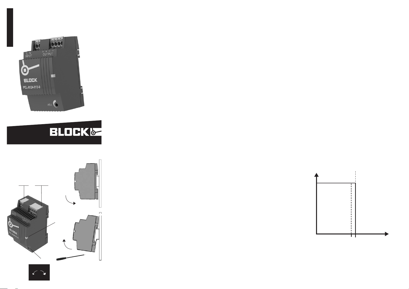
Installation
Installation
Sicherheitsmaßnahmen vor der Installation
Das Betriebsmittel ist vor unzulässiger Beanspruchung zu
schützen. Insbesondere dürfen bei Transport und Handhabung keine Bauelemente verbogen und/oder Isolationsabstände verändert werden. Die Berührung elektrischer
Ba u ele ment e und Ko n t akte is t zu ver m eid e n. Da s Betri e bsmittel immer im spannungsfreien Zustand montieren und
verdrahten. Die Produktbeschreibung und die technischen
Hinweise in unserem Hauptkatalog sowie die Aufschriften
am Be t rieb smit t e l und au f dem Typen s chi l d sin d zu bea c hten.
Installation
Di e Inst a lla t ion is t entsp rech e nd de n örtli c hen Ge gebenheiten, einschlägigen Vorschrift en (z. B. VDE 0100),
nationalen Unfallverhütungsvorschriften (z. B. UVV-VBG4
bzw. BGV A3) und den anerkannten Regeln der Technik
durchzuführen. Dieses elektrische Betriebsmittel ist eine
Komponente, die zum Einbau in elektrische Anlagen oder
Maschinen bestimmt ist und erfüllt die Anforderungen der
Niederspannungsrichtlinie (2014/35/EU). Der geforderte
Mindestabstand zu benachbarten Teilen ist einzuhalten, um
die Kühlung nicht zu behindern! Bei Einbau in Maschinen ist
die Aufnahme des bestimmungsgemäßen Betriebes solange
untersagt , bis festgestellt wurde, dass die Maschine den
Bestimmungen der Maschinenrichtlinie (2006/42/EG)
entspricht. EN 60204 ist zu beachten. Die Aufnahme des
bestimmungsgemäßen Betriebes ist nur bei Einhaltung der
EMV-Richtlinie (2014/30/EU) erlaubt. Die Einhaltung der
durch die EMV-Gesetzgebung geforderten Grenzwerte
liegt in der Verantwortung des Herstellers der Anlage oder
Maschine.
Safety measures before installation
This equipment is to be protected against improper use.
Components are not to be bent or isolation spacing changed,
especially through handling and transport. The contact with
electrical components and terminals is to be avoided. Always
disconnect the equipment from the mains supply, before
commencing installation or wiring. The product description,
technical information in our main catalogue and the marking
on th e equi pme n t rati ngs pl ate ar e to be obs e rved .
Installation
Installation must be carried out according to the prevailing
local conditions and safety regulations (e.g. VDE 0100)
national accident prevention regulations (e.g. UVV-VBG4 or
BGV A3) and the generally accepted rules of technology. This
eq u ipm ent is a co mpo nent de sig ned fo r inst a lla t ion in t o ele c trical systems and machines, and fulfils the requirements of
the low voltage guidelines (2014/35/EU).
The required minimum spacing to neighbouring components must be observed to guarantee the required cooling.
When installed into machinery, the normal operation is
forbidden until it is determined that the machine fulfils
the re qui r eme n t s of the mac hin e ry gui del ines (2 006 /4 2/
EG). EN 60204 must be observed. The EMC requirements
(2 014 /30 / EU) must be fu lfil l ed be f o re ope rati o n is com menced. The observance of the required limitations for the
EMC legislation is the responsibility of the manufacturer of
the inst a lla t i on or machi ner y .
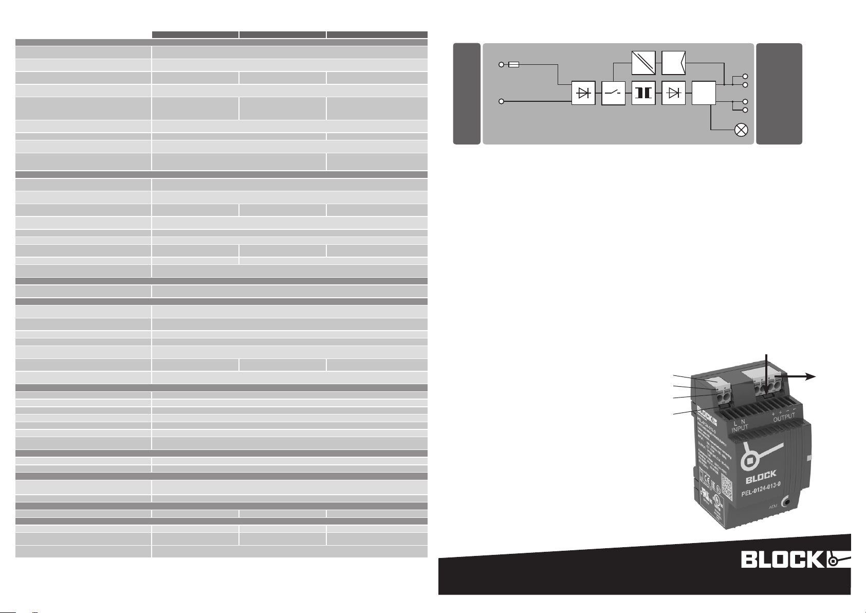
Anschluss
Connection
Eingang
3 4
input
L N
Ausgang
output
+ + – –
U
out
2
LED: Di e grü n e LED leu chtet , so f ern
5
6
1
+–
1
die Ausgangsspannung vorhanden ist.
Ausgangsspannung: Die Aus-
2
gangsspannung kann mit einem
Schraubendreher verändert werden.
Drehung im Uhrzeigersinn erhöht die
Ausgangsspannung. Drehung gegen
den Uhrzeigersinn verringert die
Ausgangsspannung.
Eingang
3
Ausgang
4
Montage: Setzen Sie das Gerät mit
5
de r Trags c hie nenf ü hru n g an di e Ober ka n te der Trags c hie n e an un d rast e n
Si e es nac h unten ein.
Demontage: Ziehen Sie den
6
Schnappriegel mit Hilfe eines
Schraubendrehers auf und hängen
Sie das Gerät an der Unterkante der
Tragschiene aus.
LED: The green LED lights as soon as
1
the outpu t volta g e is pr e sen t .
Output voltage: The output voltage
2
ca n be alt e r ed usi ng a sc r ewdr i ver.
Tur ning the adj ust m ent sc r ew clo c kwi s e rai s es the outpu t volta g e. Tur ni ng the adju s tmen t screw antic l ock wi s e redu c e the ou t put vo ltag e .
Input
3
Output
4
Mounting: Place the device with the
5
DIN rail guide on the upper edge of the
DIN rail, and snap it in with a
downward motion.
Removing: Pull the snap lever open
6
with the aid of a screwdriver and slide
the device out at the lower edge of the
DIN rail.
Ausgangskennlinie (U/I Kennlinie)
Output characteristic (U/I Characteristic)
U
(V)
out
IN
1,1 x I
N
(A)
I
out
Technische Daten
Technical data
Eingangsdaten Input
Eingangsnennspannung
Rated input voltage
Eingangsspannungsbereich
Operating input voltage range
Eingangsspannungs-Derating
Derating input voltage
Nennfrequenzbereich
Rated frequency range
Eingangsnennstrom bei Nennlast
(11 0 / 230 Va c)
Rated input current at nominal load
110 / 230 Vac)
Einschaltstrombegr enzung
In-rush current limiter
Eingangssicherung intern int ern al fus e 2 AT 4 AT
Empfohlene Vorsicherung*
Recommended external protection*
Ne tza us fal lü be rb rüc ku ng be i Ne nn la st (110 / 23 0 Vac )
Mains drop compensation at nominal load (110 / 230
Vac)
Ausgangsdaten Output
Ausgangsspannung
Rated output voltage
Ausgangsspannungsbereich
Rated output voltage range
Ausgangsstrom
Rated output current
Überlastverhalt en
Overloadbehaviour
Parallelschaltbar
Serienschaltbar
Verlustleistung (Leerlauf / Nennlast / Maximum)
Power loss (idle / nominal load / maximum)
Wirkungsgrad Efficiency ty p. 82 % ty p. 88 %
Restwelligkeit (Nennlast)
Residual ripple (nominal load)
Signalisierung Signaling
Betriebsanzeige
Power indicator
Um welt Environment
Lagertemperatur
Storage Temperature
Umgebungstemperatur
Ambient termperature
Derating -3 %/ K > +4 5 °C
Einbaulage Mounting position wa ag ere ch t für Tr ag schie ne TH 35 , ho riz on ta l for rai l TH 35
Zulässige Luftfeuchtigkeit
Allowable humidity
Strombelastbarkei t bei beliebiger Einbauanlage
Cu rr ent rat ing at an y mou nt in g pos it ion
Kü hl ung ( Ab sta nd zu be nac hb art en Tei le n)
Cooling (spacing to vicinal components)
Si cher hei t und S ch ut z Safety and protection
Sc hut za rt Protection index IP 20
Prüfspannung
Schutzklasse Safety class II (im ge sc hl oss en en Sch alt sch ra nk ) II ( in t he cl os ed cab ine t)
An sch lu ss ka be l
Ei ns atz be rei ch
Üb er spa nn un gs ka teg or ie
Rückspeisungsfestigkeit
Feedback voltage
No rmen Safety standards
Sicherheit Safety EN 615 58 -2-1 6, EN 609 50 -1
EMV EMC EN 612 04 -3
Zulassungen Approvals
UL
GL Environmental category: C, EMC2
Bestellnummern Order numbers
Mechanik Mechanical Data
Gewicht wei gh t 0. 17 kg 0. 24 kg 0. 3 kg
Ma ße ( B x H x T )* *
Dimens ions width x heigh t x depth**
An sch lü ss e Ei ngan g (L, N) / Aus gan g (+, +, - , -) ***
Ter mina ls in pu t (L, N) / out put (+, +, -, -) ***
* Für DC Eingangsspannung ist eine
geeignete DC-Sicherung erforderlich.
* For DC input voltage suitable DC fuse
required.
Parallel operation
Serial operation
HV te st vol tag e 4242 Vdc
Conductors Zu m An sch lu ss Kup fer kab el m it min . 75 °C ver wen de n Use c op per c on du cto rs on ly , ra ted 75° C
Installation Ei ns at z in Be rei ch en mi t Ve rs chm ut zun gs gr ad 2 Fo r ins ta llat ion in po llu ti on de gr ee 2 en vi ron me nt
Overvoltage category II
** Tiefe T ab Oberkante Tragschiene.
** Depth from upper edge of DIN rail.
PEL-0124-013-0 PEL-0124-025-0 PEL-0124-040-0
10 0 - 24 0 Va c
85 - 264 Vac (12 0 - 373 Vd c)
ma x. 1 A (< 10 0 Va c)
0. 7 / 0. 5 A 1. 4 / 0.6 A 1. 6 / 0. 9 A
6 A, 10 A , 16 A, C ha ra kt eri sti k B, C 6 A, 10 A, 16 A , Ch ara ct eri st ic B, C
1. 3 A 2. 5 A 4 A
2. 6 W / 7 W / 7.3 W 2. 2 W / 8. 5 W / 10. 5 W 0. 8 W / 13 .1 W / 14. 8 W
-2 5 °C – +6 0 °C (U L: - 25 °C – + 55 ° C)
ma x. 0. 9 A ma x. 1. 6 A max . 2.4 A
ke in Min des ta bst an d rec ht s/l in ks er for de rlich , 50 mm ob en /unt en
UL- No te: Outp ut di sc onn ec tin g me ans sha ll be pro vid ed du ri ng in st all at ion .
PEL-0124-013-0 PEL-0124-025-0 PEL-0124-040-0
54 x 89 x 55 mm 72 x 89 x 55 mm 90 x 89 x 55 mm
ma x. 2 A (< 1 00 Vac ) /1.8 A (<
90 Vac )
44 H z - 66 Hz / 0 H z
< 30 A, N TC
10 / 80 ms 15 / 100 ms
24 Vd c ±2 %
22 .8 - 26. 4 Vdc
Ko ns tan ts tro m (U/ I Ke nnl in ie ) Const ant c ur re nt (U /I Li ne )
5 bi s 96 % re la ti ve Fe uch te , kei ne Bet auu ng zul ässig
5 to 96 % r el at ive hum idi ty wi th no de w
No min imum sp ac in g rig ht /le f t re qui re d, 50 mm ov er /u nd er
UL 508 (li ste d), UL 60 950- 1 (r eco gniz ed)
WAG O pic oM AX® eCO M 5.0 ser ies 2 09 2, max . 2,5 mm²
*** picoMAX nur im spannungslosen Zustand ziehen oder stecken. Zum
Ziehen die Entriegelung mit Betätigungswerkzeug auslenken und picoMAX am
Steckergehäuse herausziehen, nicht an den Leitungen.
*** Pull or plug picoMAX in a powered down state. For pulling deflect the unlocking with operating tool. Pull picoMAX on the plug housing, not on the wire.
Ja Yes
Ja Yes
ty p. 10 0 mV
LE D grü n LE D gr een
-2 5 °C bi s +8 0 °C
Anlauf bei -40 ° C typgeprüft Device start at -40 ° C type-tested
ma x. 30 Vd c
ma x. 3. 5 A (< 100 Vac ) / 3 A (< 90 Va c)
ss2
Funktionsschaltbild
Functional diagram
L (–)
N (+)*
* Zweiphasenbetrieb nur möglich, sofern die maximale Eingangsspannung von 264 Vac nicht überschritten wird.
* Two phase operation only possible, if input voltage under 264 Vac.
picoMAX-Federleisten bitte nur im spannungslosen Zustand
ziehen oder stecken.
Zu m Zieh en bit t e die En t r ieg e lun gsl a sch e (1) mit einem
Be t ä t igu ngs w erkze ug au slen ken un d pic o MAX am Fe derleistengehäuse (2) herausziehen, nicht an den angeschlos-
senen Leitungen.
Beim Stecken darauf achten, dass die picoMAX-Federleiste
hö r bar einra stet. Gg f. du r ch Rüt t e ln de n Festsi t z kont r ollieren.
Starre Leiter oder Leiter mit Aderendhülse können direkt
gesteckt werden, bei flexiblen Leitern bitte den orangen
Betätigungsdrücker zum Öffnen der Klemmstelle nutzen.
Abisolierlänge 9..10 mm. Leiterquerschnitt ohne Aderendhü lse 0, 2 mm² .. . 2,5 mm ², mit Ad eren hüls e 0,25 mm² .. . 1,5
mm².
Das Lösen aller Leiterarten erfolgt über das Öffnen der
Kle mms t e lle mi t t els de s ora ngen Be t ätig ung sdrü cker s (3).
Ei ne Prü f ö f f nun g (4) an jeder Klemmstelle erlaubt die
Please pull or plug picoMAX-female connectors only in a
powered down state.
Fo r pull ing de f lec t th e unl o ckin g (1) with an operating tool.
Pu l l pic o MAX on th e hous ing (2), not on th e conn e cted wi r es.
When inser ting, make sure that the picoMAX female
connector clicks audible. If necessary, test the tightness by
vibration.
Rigid conductors or conductors with ferrules can be
inserted directly. For stranded conductors please use the
orange actuating pusher for opening the terminal point.
Stripping length 9..10 mm. Conductor cross-section without
wire end-ferrules 0.2 mm² ... 2.5 mm², with wire-end ferrules
0. 25 mm ² ... 1.5 mm².
At all types of conductors the release is done with opening of
the te rmi nal po int vi a the or a nge ac tuat i ng pu shb u t t on (3).
A tes t hole (4) on each terminal point allows voltage test
wi t h out op eni n g the te r min al po i nt by 1m m pro b e.
Spannungsprüfung ohne Öffnen der Klemmstelle mittels
Pr ü f spi t z e 1 mm.
2
4
3
1
BLOCK Transformatoren-Elektronik GmbH
Max-Planck-Straße 36-46 . 27283 Verden, Germany
info@block.eu . block.eu
Technische Änderungen vorbehalten.
Subject to change.
Stand-by
–
–
+
+
LED (Green)
block.eu
1.
2.
 Loading...