

Biostar P4M900 Micro 775 Owner's Manual

P4M900 Micro 775 Setup Manual
FCC Inf or m at ion and Copyright
This equipment has been tested and found to comply with the limits of a Class
B digital devic e, pursuant to Part 15 of the FCC Rules. T hese limits are designed
to provide reas onab le protec tion against harmful i nterfe rence in a resi dential
installation. T his equipment generates , uses and can radiate radio frequency
energy and, if not ins talled and used in accordance with the instructions, may
cause harmful interference to radio communications. There is no guarantee
that i nterfe rence wil l not occur in a particula r ins ta llati on.
The ve ndo r ma kes no re prese nta tions or warra nties with respec t to the
contents here and specially disclaims any implied warranties of merchantability
o r fi tn es s fo r a ny p u rp os e . F u rt he r t he ve nd o r res e rves the ri ght to rev ise this
publication and to make c hanges to the contents here without obligation to
notify any party beforehand.
D uplicati on of t his publicat ion, i n pa rt o r in whole , is no t allo wed wi thout fi rst
obtaining the vendor’s approval in writing.
The content of this user’s manual is subject to be changed without notice and
we will not be responsible for any mistakes found in this user’s manual. All the
brand and product names are trademarks of their respective companies.

Table of Contents
Chapter 1: INTRODUCTION........................................ 3
1.1 Before You Start...................................................................3
1.2 Package Checklist................................................................ 3
1.3 Motherboard FeaturesS.........................................................4
1.4 Rear Pa nel Co n necto rs (for Ve r 5.x) ....................................... 6
1.5 Rear Pa nel Co n necto rs (f or Ver 6.x)....................................... 6
1.6 Mo t he r boa r d Layou t (for Ve r 5.x).......................................... 7
1.7 Mot her boa r d Layou t (fo r Ver 6.x).......................................... 8
Chapter 2: Hardware Installation..............................9
2.1 Installing Central Proce ssing Unit (CPU) ................................ 9
2.2 Fan Headers........................................................................11
2.3 Installing Sy stem Me mory.....................................................12
2.4 Con nectors a nd Slo ts............................................................13
Chapter 3: Headers & Jumpers Setup .....................15
3.1 How to Se t u p Ju mpe r s..........................................................15
3.2 Det ail Settin gs.....................................................................15
Chapter 4: USEFUL HELP..........................................21
4.1 Dr i ver Instal latio n Note.......................................................21
4.2 Award BIOS Bee p Code........................................................22
4.3 Extra Information................................................................22
4.4 Troubleshooting...................................................................24
Chapter 5: WarpSpeeder™ .......................................25
5.1 Introduction........................................................................25
5.2 System Requirement............................................................25
5.3 Installation.........................................................................26
5.4 WarpSpeeder™....................................................................27
Appendencies: SPEC In Other Language ................34
German................................................................................................34
France..................................................................................................36
Italian..................................................................................................38
Spanish................................................................................................40
Portuguese...........................................................................................42
Polish...................................................................................................44
Russian................................................................................................46
Arabic..................................................................................................48
Japanese..............................................................................................50

P4M900 Micro 775
CHAPTER 1: INTRODUCTION
1.1 BEFORE YOU START
Tha nk you fo r choo sing our produ ct. Befo re you s tart ins talling the
mo therboa rd, plea se make sure you follo w the ins tructio ns be lo w:
Prepare a dry and stable working environment with
s uf fi cie nt li gh ting .
Always disconnect the computer from power outlet
be fo re ope ration.
Befo re you take the m o the rboa rd ou t f rom a n ti-s ta ti c
bag, ground yourself properly by touching any safely
grounde d ap pliance, or use grounded wrist s trap to
remove the static charge.
Avo id to u ch ing the com pone nts on mo the rboa rd o r the
rea r side of the boa rd unless ne cessary. Ho ld the boa rd
on the edge , do not try to be nd o r flex the board.
Do no t leave any unfas tened sma ll pa rts inside the
case after installation. Loose parts will cause short
circuits which ma y damage the equ ipment.
Keep the computer from dangerous area, such as heat
source, humid air and water.
1.2 PACKAGE CHECKLIST
HDD Cable X 1
Use r’s Ma nua l X 1
Fully Setup Driver CD X 1
Rear I/O Panel for ATX Case X 1
FDD Cable X 1 (optional)
Se ria l ATA C ab le X 1 ( op ti ona l)
USB 2.0 Cable X1 (optional)
S/PDIF Cable X 1 (optional)
Se ria l ATA Po we r Cab le X 1 (o ptio nal)
3
Motherboard Manual
/
p
/
p
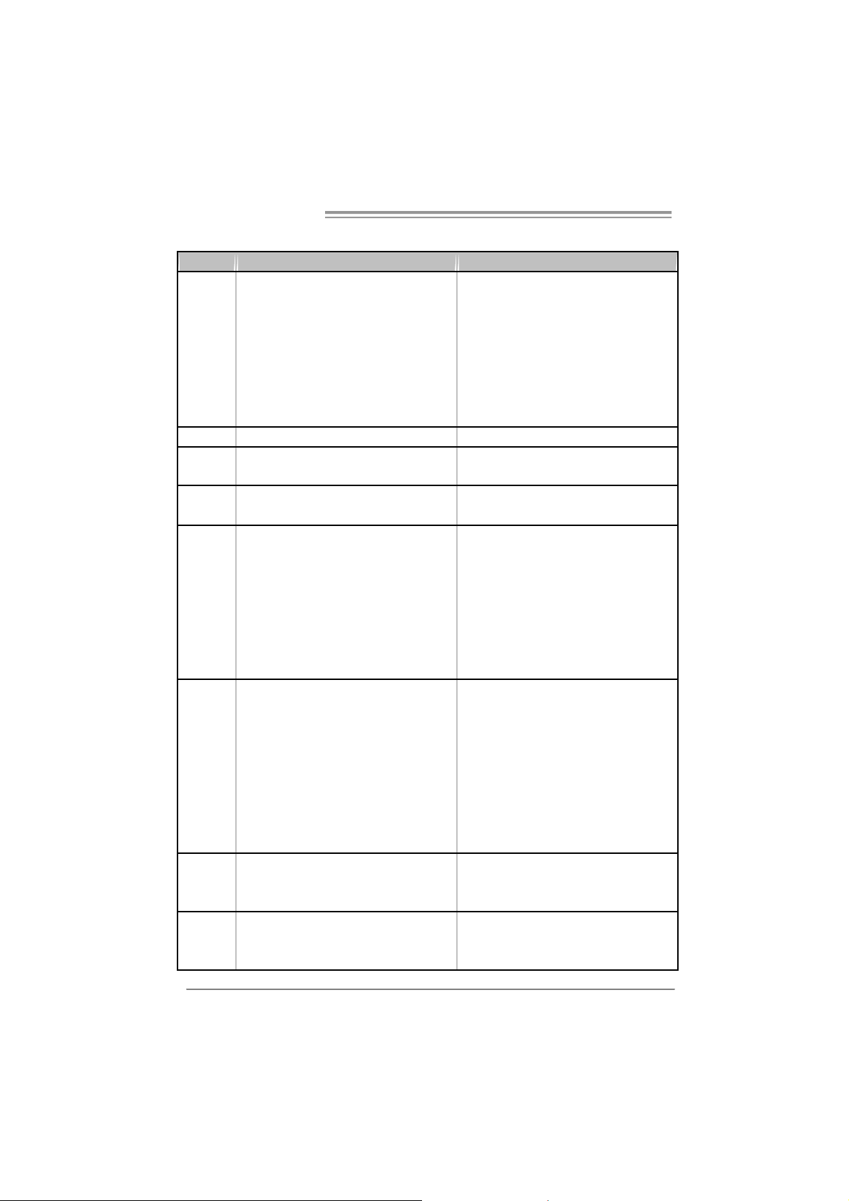
1.3 MOTHERBOARD FEATURESS
Ver 5.x Ver 6.x
LGA 77 5
Intel Core2Duo/ Pentium 4 / Pentium D /
Celeron D processor up to 3.8 GHz
CPU
FS B 533 / 800 / 106 6 M Hz 533 / 800 / 106 6 M Hz
Chipset
Graphic
Super I/O
Main
Memory
IDE
SATA
Supports Hyper Threading
Bit / Enhanced Intel S peedSt ep®/ Intel
Extended Memory 64 technology
*It is recommended to use
95W power co nsumption.
VIA P4M900
VIA VT8237A
Chr om e9 HC 3D / 2D Grap hic s
Max Shared Video Memory is 256 MB
ITE 871 2F
Provides the most commonly used legacy
Super I/O functionality.
Low Pin C ount Interf ac e
Environment Control initiatives,
H/W Monitor
Fan S pee d Co nt r ol ler
ITE' s "Smart G uardi a n" fu nc t i on
DIMM Slots x 2
Supports D DR2 5 33 / 667
Eac h DIMM s up ports 2 56/51 2MB/1GB / 2GB
DDR2
Max Memory Capicity 4GB
Single Channel Mode DDR2 memory
module
Registered DIMM and ECC DIMM is not
support ed
Integrated I DE Controller
Ultra DMA 33~133 Bus Master Mode
support s PIO Mo de 0~ 4,
Integrated Serial ATA Controller
Data transfer rates up to 1.5 Gb/s.
SATA Version 1.0 specification compliant.
Execute Disable
rocessors with
LGA 77 5
Intel Core2Duo/ Pentium 4 / Pentium D /
Celeron D processor up to 3.8 GHz
Supports Hyper Threading
Bit / Enhanced Intel S peedSt ep®/ Intel
Extended Memory 64 technology
*It is recommended to use
95W power co nsumption.
VIA P4M900
VIA VT8237A
Chr om e9 HC 3D / 2D Grap hic s
Max Shared Video Memory is 256 MB
ITE 871 2F
Provides the most commonly used legacy
Super I/O functionality.
Low Pin C ount Interf ac e
Environment Control initiatives,
H/W Monitor
Fan S pee d Co nt r ol ler
ITE' s "Smart G uardi a n" fu nc t i on
DIMM Slots x 2
Supports D DR2 5 33 / 667
Eac h DIMM s up ports 2 56/51 2MB/1GB / 2GB
DDR2
Max Memory Capicity 4GB
Single Channel Mode DDR2 memory
module
Registered DIMM and ECC DIMM is not
support ed
Integrated I DE Controller
Ultra DMA 33~133 Bus Master Mode
support s PIO Mo de 0~ 4,
Integrated Serial ATA Controller
Data transfer rates up to 1.5 Gb/s.
SATA Version 1.0 specification compliant.
Execute Disable
rocessors with
4
P4M900 Micro 775
g
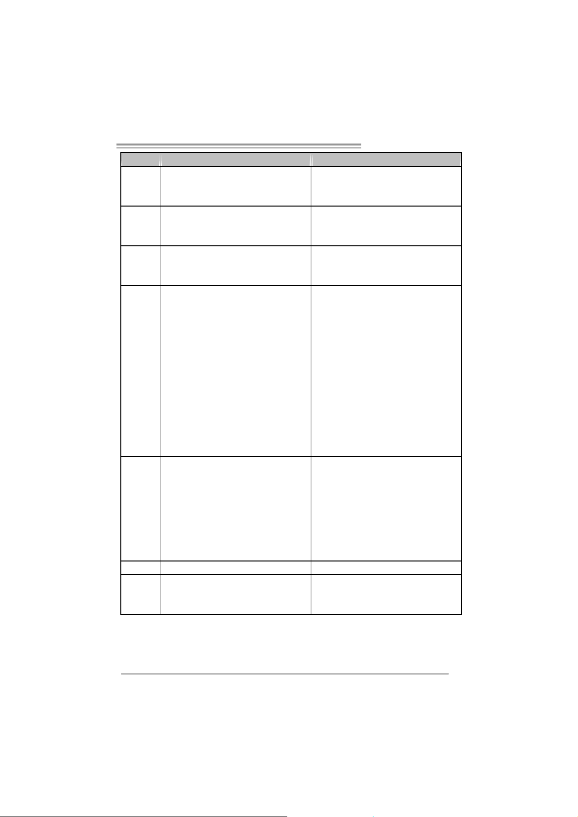
Ver 5.x Ver 6.x
Realtek RTL 8201CL
LAN PHY
Sound
Codec
On Board
Connector
Back Panel
I/O
Board Size 190 mm (W) x 24 4 m m (L ) 190 mm (W) x 24 4 m m (L )
OS
Suppor t
10 / 100 Mb/s auto negotiation
Half / Full duplex capability
AL C 888
7.1 c ha nnels a udio out
High- Defi nition A u dio s upport
PCI Express x 16 slot x1 PCI Express x 16 slot x1
PCI Express x 1 slot x1 PCI Express x 1 slot x1 Slots
PCI s lot x2 PCI slot x2
Floppy connector x1 Floppy connector x1
IDE C o nnect or x2 IDE Co nnector x2
SATA Connector x2 SATA Connector x2
Front Pa nel C o nnect or x1 Front Pa nel Co nnect or x1
Front Audi o Connect or x1 Front Audi o Co nnect or x1
CD-in C o nnector x1 CD-i n Co nnect or x1
S/PDIF out connector x1 S/PDIF out connector x1
CPU Fan hea der x1 CPU Fan hea der x1
Sys t em F an hea der x1 System Fan hea der x1
Clear CMOS header x1 Clear CMOS header x1
USB connector x2 USB connector x2
Power Connector (24pi n) x1 Power Connector (24pin) x1
Power Connector (4pin) x1 Power Connector (4pin) x1
PS/2 Keyb oard x1
PS/2 Mo use x1
Serial Port x1
Printer Port x1
VGA Port x1
LAN port x1
USB Port x4
Audio Jack x6
Windows 2000 / XP / VISTA
Biostar Reserves the ri
support for any OS with or without notice.
ht t o add or remo ve
Realtek RTL 8201CL
10 / 100 Mb/s auto negotiation
Half / Full duplex capability
AL C 861V D
5.1 c ha nnels a udio out
High- Defi nition A u dio s upport
PS/2 Keyb oard x1
PS/2 Mo use x1
Serial Port x1
Printer Port x1
VGA Port x1
LAN port x1
USB Port x4
Audio Jack x3
Windows 2000 / XP / VISTA
Biostar Reserves the right t o add or remove
support for any OS with or without notice.
5
Motherboard Manual
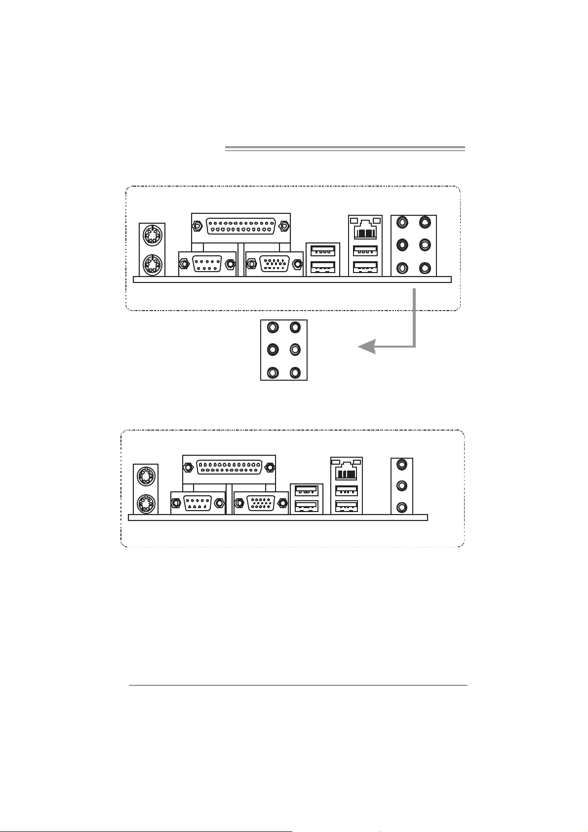
1.4 R
EAR PANEL CONNECTORS (FOR VER 5.X)
PS /2
Mouse
PS/2
Keyboard
Printer Port
COM1 VGA
Center
Rear
Side
Li ne I n
Li ne O u t
Mic In
LAN
USBX2USBX2
1.5 REAR PANEL CONNECTORS (FOR VER 6.X)
PS/2
Mouse
Printer Po rt
LAN
AUDI O JAC K
Line I n/
Surro und
Line Out
PS/2
Keyboard
Since t he audio chip supports High Definiti on A udio Specific ation, the func tion of eac h audi o
jack can be defined by software. T he input / out put function of each audio jac k listed above
represents the default setti ng. However, when connecti ng exter nal microphone to t he audio
port, please use the Line In (blue) and Mic In (Pink) audio j ack.
6
COM1 VGA
USBX2USBX2
Mic In 1/
Bass/ C enter
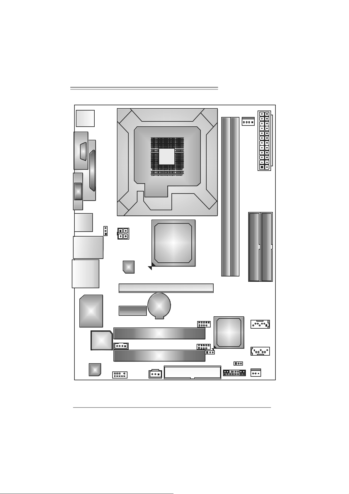
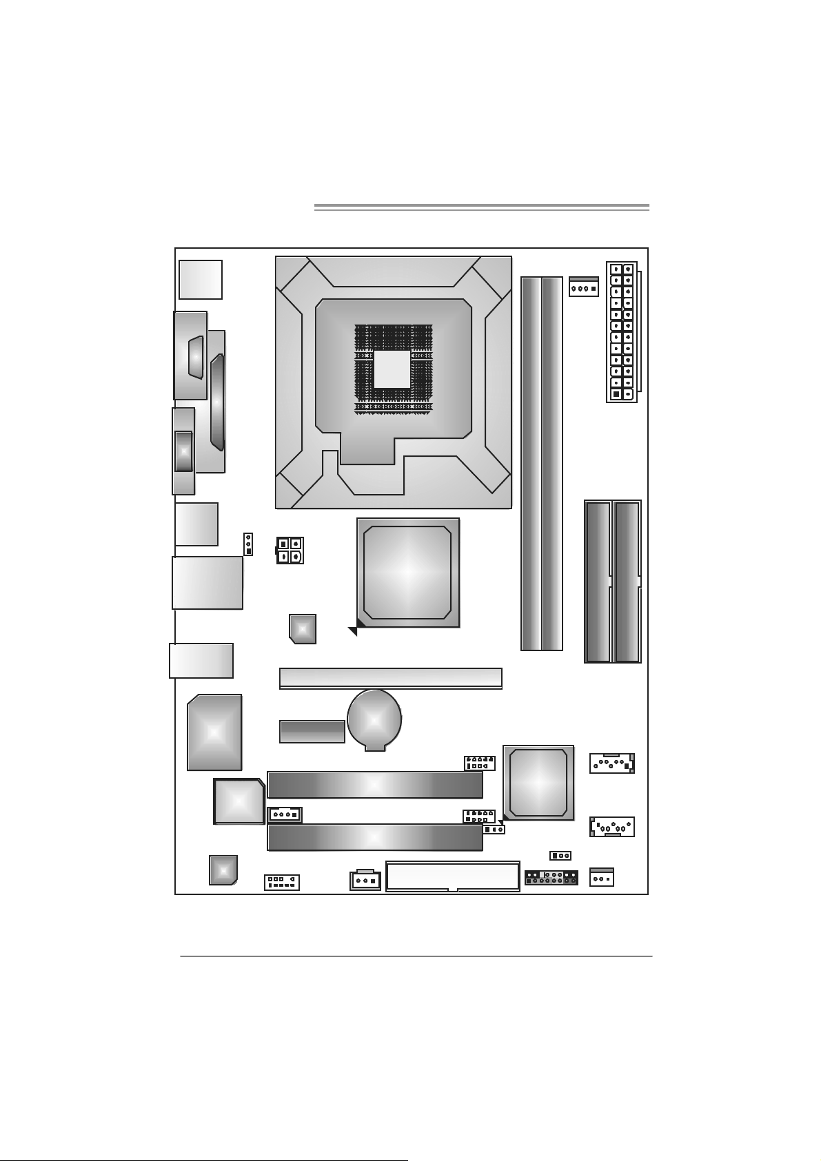
1.6 MOTHERBOARD LAYOUT (FOR VER 5.X)
P4M900 Micro 775
JKBMS1
C
O
J
M
C
1
O
M
1
JPRNT1
JVGA1
JUSB2
JRJ45USB1
JAUDIO1
JUSBV1
JATXPWR 2
LAN
LGA775
CPU1
P4M900
JCFAN1
JAT XPWR1
DDR2_B1
DDR2_A1
IDE1
IDE2
Super
I/O
BIOS
Code c
Note: represents the 1■
JCDIN1
JAUD IO2
PCI-EX1_1
BAT1
PCI1
PCI2
JSPDIF_OUT1
PCI-EX16
st
pin.
JUSB2
JUSB3
FDD1
JUSBV2
VIA
VT8237A
JC MOS 1
JPANEL 1
JSAT A 2
JSAT A1
JSF AN1
7
Motherboard Manual
1.7 MOTHERBOARD LAYOUT (FOR VER 6.X)
JKBMS1
COM1
JCOM1
JPRNT1
JVGA1
JUSB2
JRJ45USB1
JAUDIO1
JUSBV1
JATXPWR 2
LAN
LGA775
CPU1
P4M900
PCI-EX16
JCFAN1
JATXPWR1
DDR2_B1
DDR2_A1
IDE1
IDE2
8
Super
I/O
BIOS
Code c
Note: represents the 1■
JCDIN1
JAUD IO2
PCI-EX1_1
BAT1
PCI1
PCI2
JSPDIF_OUT1
st
pin.
JUSB2
JUSB3
FDD1
JUSBV2
VIA
VT8237A
JC MOS 1
JPANEL1
JSAT A 2
JSAT A1
JSF AN1

P4M900 Micro 775
CHAPTER 2: HARDWARE INS TALLATION
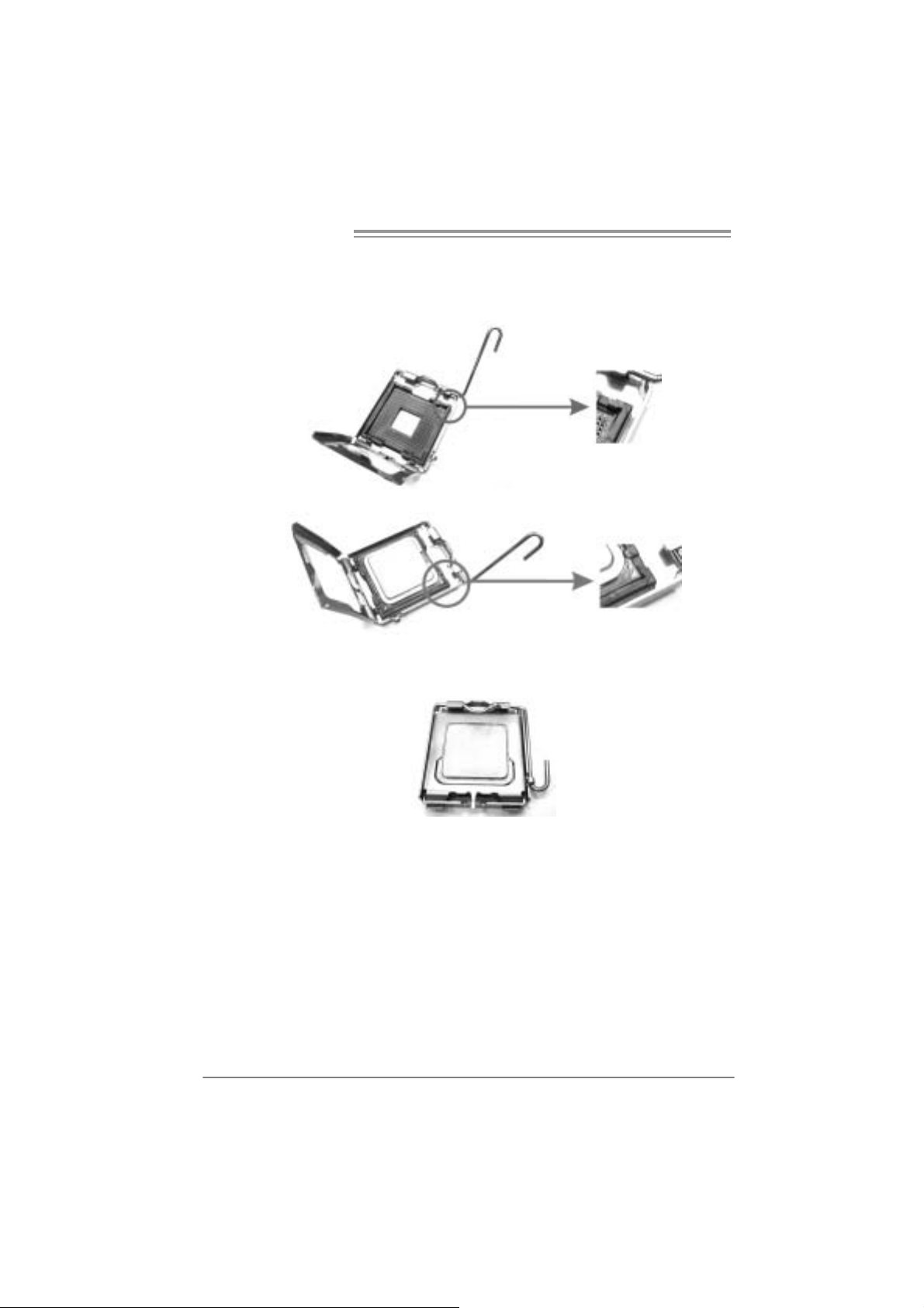
2.1 INSTALLING CENTRAL PROCESSING UNIT (CPU)
Special Notice:
Remo v e Pin Cap before installation, a nd make go o d preserv a tion
for future use. When the CPU is removed, cover the Pin Cap on the
empty so cket to ensure pin legs won’ t be dama g ed.
Pin Cap
Step 1: Pull the socket locking lever out from the socket and then raise
the lever up to a 90-degree angle.
9
Motherboard Manual
Step 2: Look for the triangular cut edge on socket, and the golden dot on
CPU should point forwards this triangular cut edge. The CPU will
fit only in the correct orientation.
Step 2-1:
Step 2-2:
Step 3: Hold the CPU down firmly, and then lower the lever to locked
position to complete the installation.
Step 4: Put the CPU Fan and heatsink assembly on the CPU a nd buckle it
on the retention frame. Connect the CPU FAN power cable into
the JCFAN1. This completes the installation.
10
P4M900 Micro 775
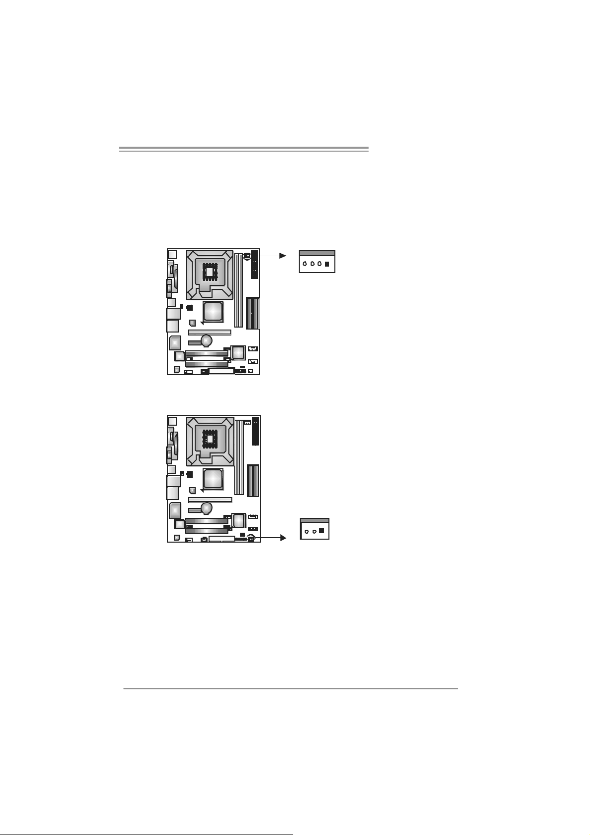
2.2 FAN HEADERS
These fan headers support cooling-fans built in the computer. The fan
cable and connector may be different according to the fan manufacturer.
Connect the fan cable to the connector while matching the black wire to
pin#1.
JCFAN1: CPU Fan Header
Pin
14
JCFAN1
JSFAN1 : System Fan Head er
JSFAN1
Assignment
1 Ground
2 +12V
3 FAN RPM rate
sense
4 Smart Fan
Control
Pin
Assignment
1 Ground
2 +12V
3 FAN RPM rate
sense
13
Note:
The JSFAN1 support 3-pi n head connector. When c onnecti ng with wires ont o connec tors,
please note that the red wire is the positi ve and s hould be c onnect ed to pin#2, and the
black wire is Ground and should be connected to GND.
11
Motherboard Manual
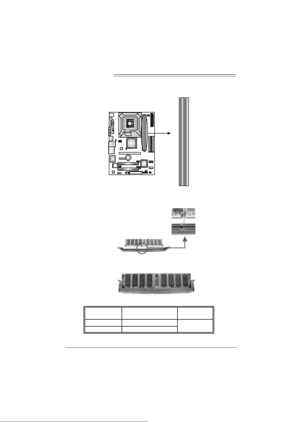
2.3 INSTALLING SYSTEM MEMORY
A. Me mo ry Modules
DDR2_B1
DDR2_A1
1. Unlock a DIMM slot by pressing the retaining clips outward. Align a
DIMM on the slot such that the notch on the DIMM matches the
break on the Slot.
2. Insert the DIMM vertically and firmly into the slot until the retaining
chip snap back in place and the DIMM is properly seated.
B. Memory Capacity
12
DI MM Socket
Location
DDR2_A1 256MB/512MB/1GB/2GB
DDR2_B1 256MB/512MB/1GB/2GB
DDR Module
To t a l Me m o r y
Size
Max is 4G B.
P4M900 Micro 775
2.4 CONNECTORS AND SLOTS
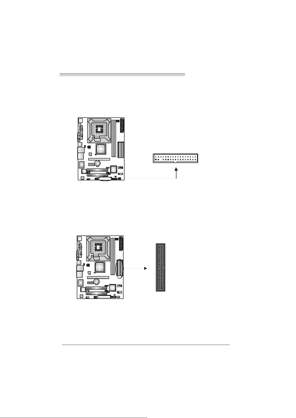
FDD1: Floppy Disk Conne c tor
The motherboard provides a standard floppy disk connector that supports 360K,
720K, 1. 2M, 1.44M and 2. 88M floppy disk ty pes. This connect or supports the
provided floppy drive ribbon cables.
IDE1/IDE2: Hard Disk Connec tors
The motherboard has a 32-bit Enhanced PCI ID E Controller that provides PIO
Mode 0~4, Bus Mas t er, and U lt ra DMA 33/ 66/100/133 functionality. It has two
HDD connect ors ID E1 (primary) and IDE2 (secondary).
The IDE connectors can connect a m aster and a s lave drive, s o y ou c an
connec t up to four hard disk drives. The first hard drive should alway s be
connec t ed to IDE1.
2
1
3940
21
34
33
IDE2IDE1
13
Motherboard Manual
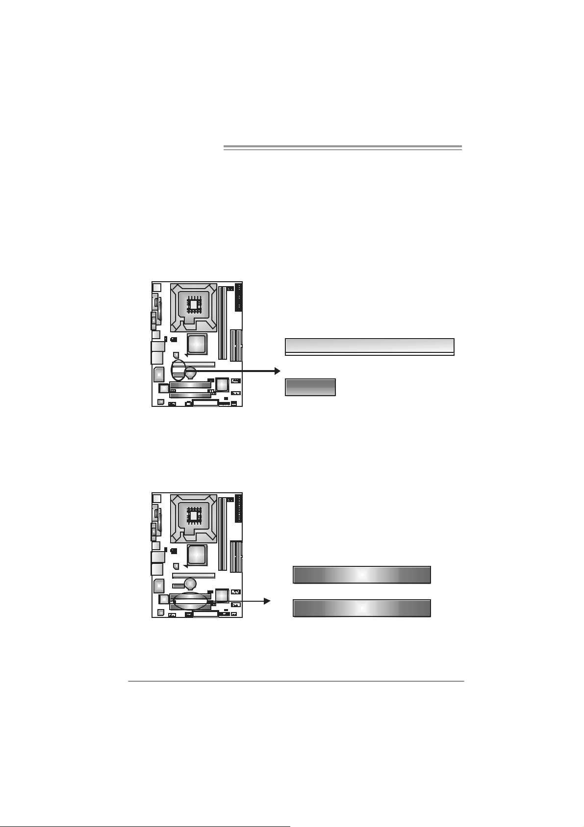
PCI-EX 16: P CI-Expre s s x1 6 S lot
- PC I -Ex press 1.0a compliant.
- Maxim um theoretical realized bandwidth of 4GB/s simultaneously per
direct ion, for an aggregate of 8GB/s totally.
PCI-EX1_1: PC I-Express x1 slots
- PC I -Ex press 1.0a compliant.
- D at a transf er bandwidth up to 250MB/s per direc t ion; 500MB/s in total.
- PC I -Ex press supports a raw bit-rate of 2.5Gb/s on the data pins.
- 2X bandwidth ov er the tradit ional PCI architecture.
PCI-EX 16
PCI-EX 1_1
PCI1~PCI2: Periphe ral Component In terconne ct Slo ts
This mother board is equipped with 2 standard PCI s l ots . PCI stands f or
Peripheral C om ponent I nterconnect, and it is a bus st andar d for ex pansion
car ds . This PCI slot is desi gnated as 32 bits.
14
PCI1
PCI2
P4M900 Micro 775
CHAPTER 3: HEADERS & JUMPERS SETUP
3.1 HOW TO SETUP JUMPERS
The illustration shows how to set up jumpers. When the jumper cap is
placed on pins, the jumper is “close”, if not, that means the jumper is
“open”.
Pin opened Pin closed Pin1-2 closed
3.2 DETAIL SETT INGS
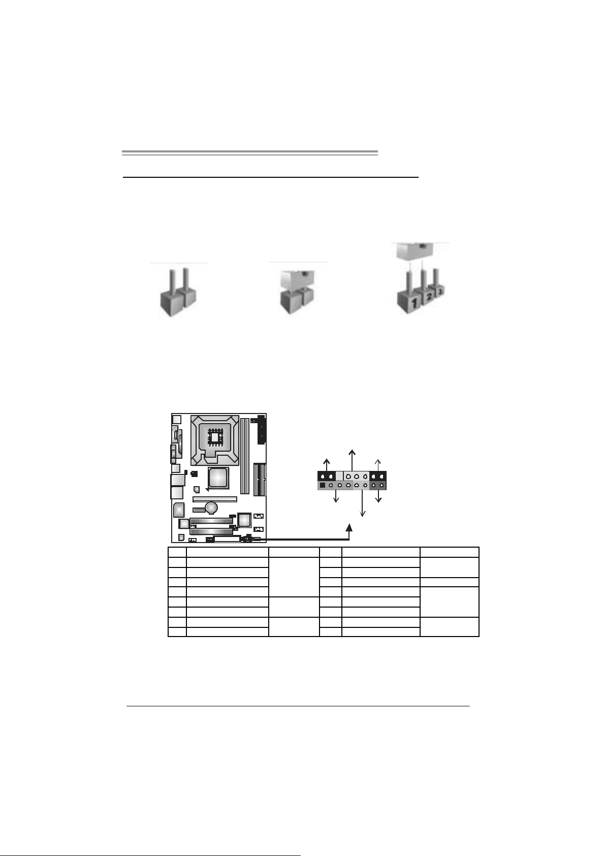
JPANEL1: Front Panel Heade r
This 16-pi n c onnect or incl udes Power-on, R eset, HDD LED, Power LED, Sleep
but ton and speaker connection. It al l ows user t o connect t he PC case’s f ront
panel s witch functions.
PWR_LED
SLP
9
1
SPK
++
HLED
+
On/Off
-
RST
16
8
Pin Assignment Functio n Pin Assignment Function
1 +5V 9 Sleep control
2 N/A 10 Ground
3 N/A 11 N/A N/A
4 Speaker
5 HDD LED (+) 13 Power LED (+)
6 HDD LED (-)
7 Ground 15 Power button
8 Reset control
Speaker
Connector
Hard drive
LED
Reset button
12 Power LED (+)
14 Power LED (-)
16 Ground
Sleep button
Powe r LED
Power-on button
15
Motherboard Manual
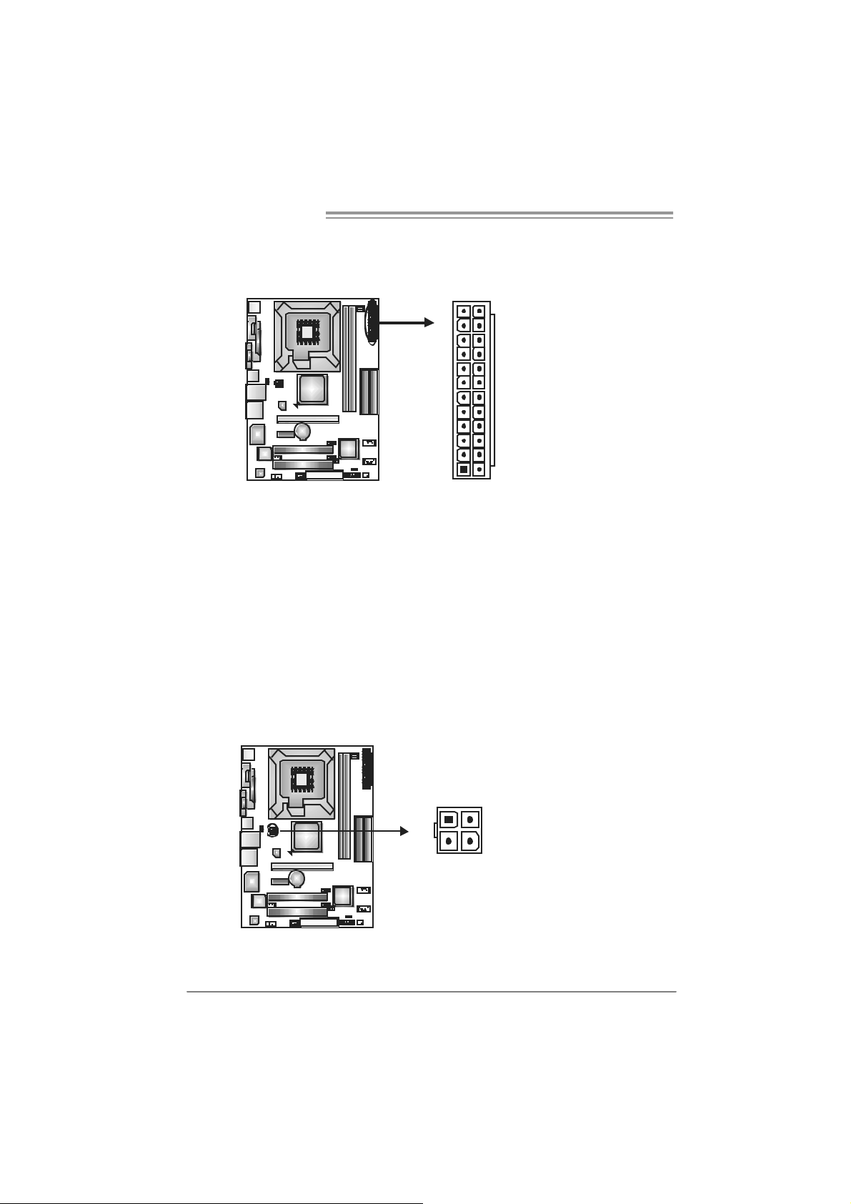
ATX Power Sourc e Connector: JAT X PWR1
JATXPWR1 all ows user to c onnect 24-pin power connector on the ATX power
supply.
12
1
Pin Assignment Pin Assignment
24
13
13 +3.3V 1 +3.3V
14 -12V 2 +3.3V
15 Ground 3 Ground
16 PS_ON 4 +5V
17 Ground 5 Ground
18 Ground 6 +5V
19 Ground 7 Ground
20 NC 8 PW_OK
21 +5V 9 Standby Voltage+5V
22 +5V 10 +12V
23 +5V 11 +12V
24 Ground 12 +3.3V
JA TXPWR2: ATX Power So u rce Conne ctor
By connecti ng this connect or, it will provide +12V t o CPU power circ uit .
Pin
1
23
4
Assignment
1 +12V
2 +12V
3 Ground
4 Ground
16
P4M900 Micro 775
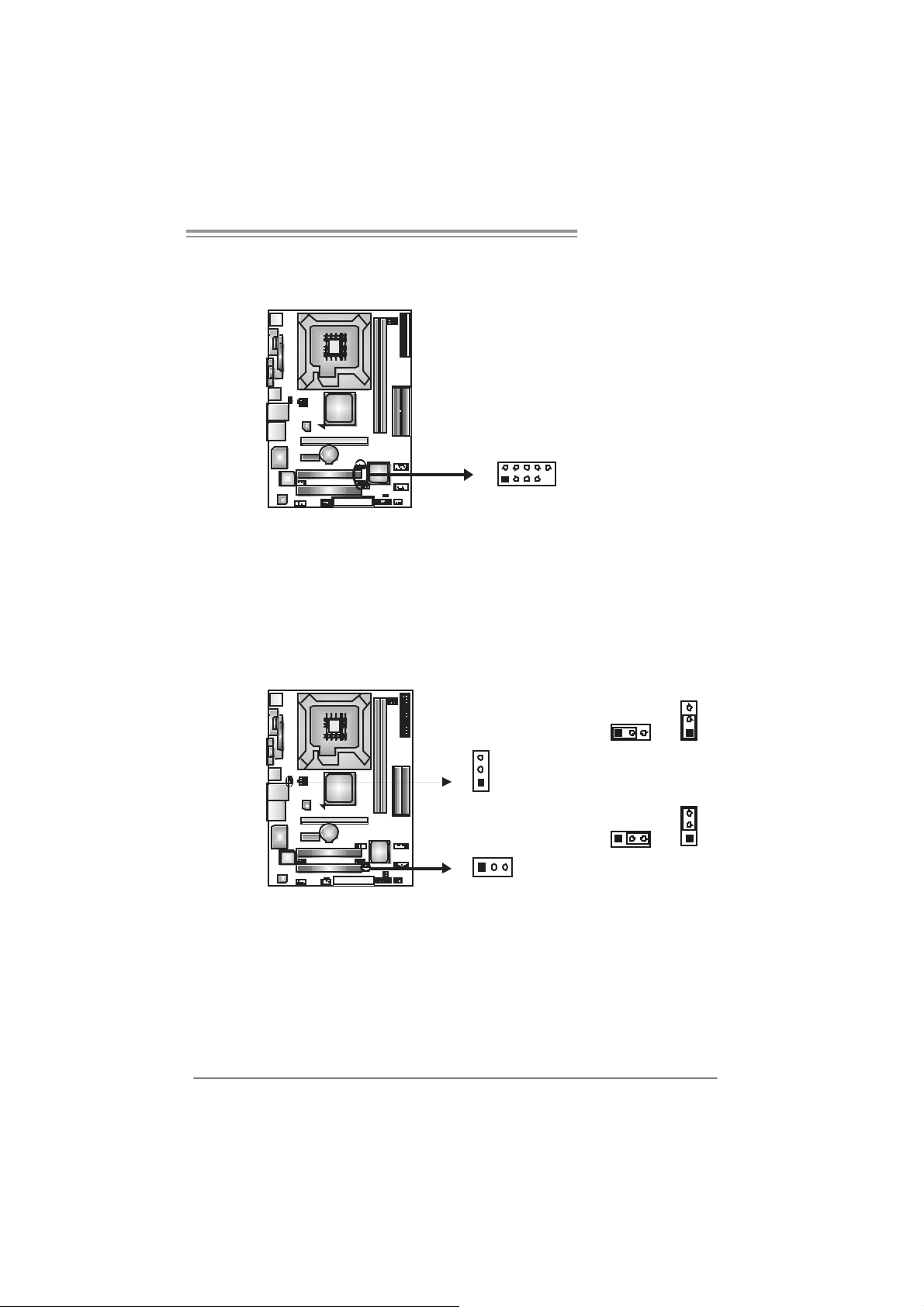
JUSB2/JUSB3: Headers for USB 2.0 Ports at Front Panel
This header al lows user t o connect additional USB cabl e on the PC fr ont panel,
and als o can be connect ed wit h i nternal USB devi ces, like USB card reader.
Assignment
Pin
1 +5V (fused)
2 +5V (fused)
3 USB4 USB5 USB+
6 USB+
7 Ground
210
19
JUSB2
JUSB3
8 Ground
9 Key
10 NC
JUSBV1/JUS BV2: Powe r S ource Headers for USB Ports
Pin 1-2 Close:
JUSBV1: +5V f o r USB ports at JRJ45USB1.
JUSBV2: +5V for USB port s at front panel (JUSB2/J USB3).
Pin 2-3 Close:
JUSBV1: USB ports at JRJ 45USB1 are powered by +5V standby voltage.
JUSBV2: USB ports at front panel (JUSB2/JUSB3) are powered by +5V
standby voltage.
3
31
1
3
1
3
1
JUSBV1
13
JUSBV2
Pin 1-2 close
1
3
Pin 2-3 close
Note:
In order to support this function “Power-On syst em via USB devic e,” “JUSBV1/ JUSBV2”
jumper cap should be placed on Pin 2-3 indi viduall y .
17
Motherboard Manual
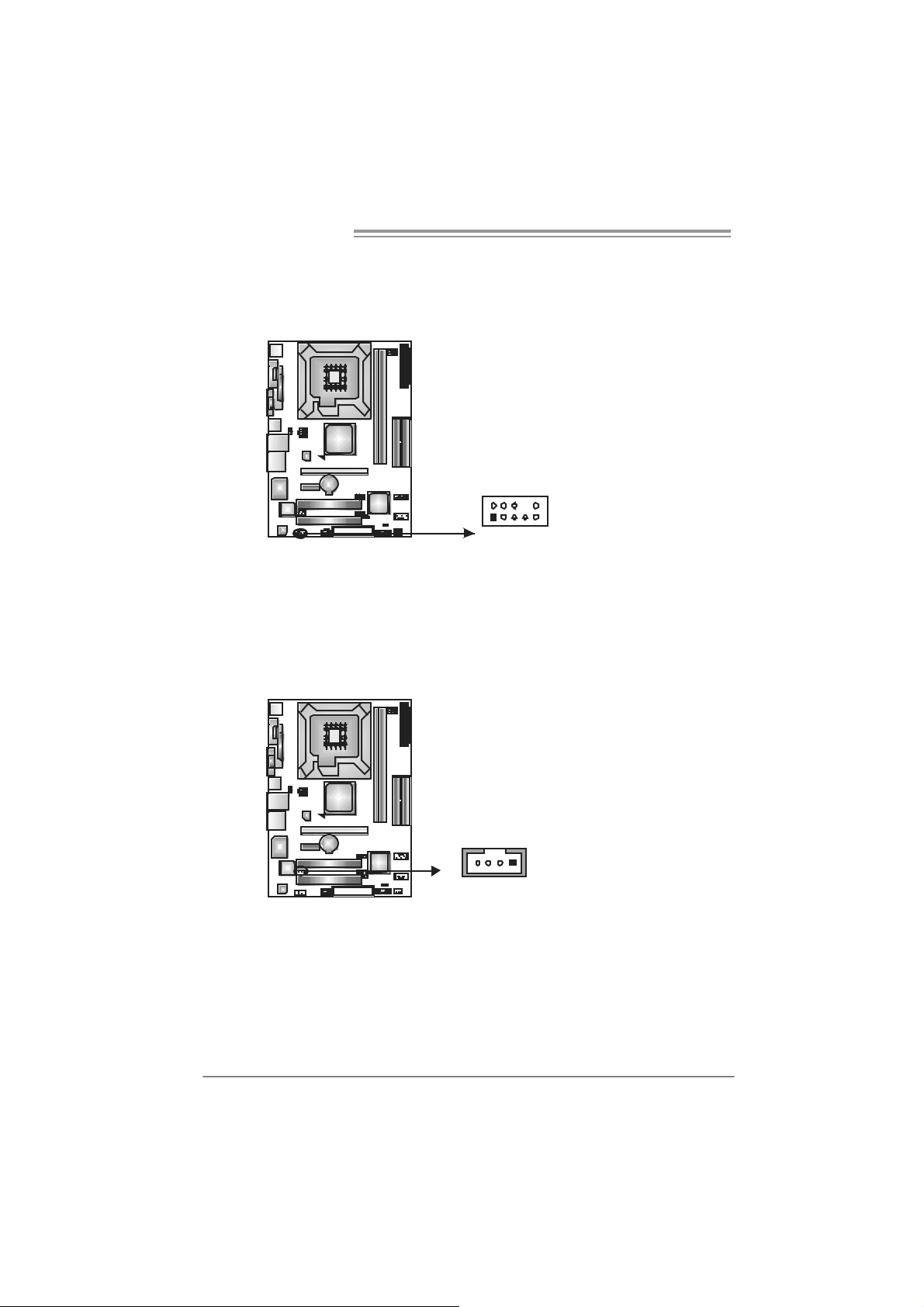
JAUDIO2: Front Panel Audio Header
This header al lows user t o connec t t he front audio output cable wit h the PC f r ont
panel. It will disable the output on back panel audio connect or s.
JCDIN1: CD-ROM A udi o-in Connector
This c onnect or allows user to c onnect the audio sourc e fr om the vari aty devices,
like CD-R OM, DVD-ROM, PCI sound car d, PCI TV turner card etc.
210
19
Pin Assignment
1 Mic Left in
2 Ground
3 Mic Right in
4 GPIO
5 Right line in
6 Jack Sense
7 Front Sense
8 Key
9 Left line in
10 Jack Sense
Assignment
Pin
1 Left Channel Input
2 Ground
3 Ground
4 Right Channel Input
18
14
P4M900 Micro 775
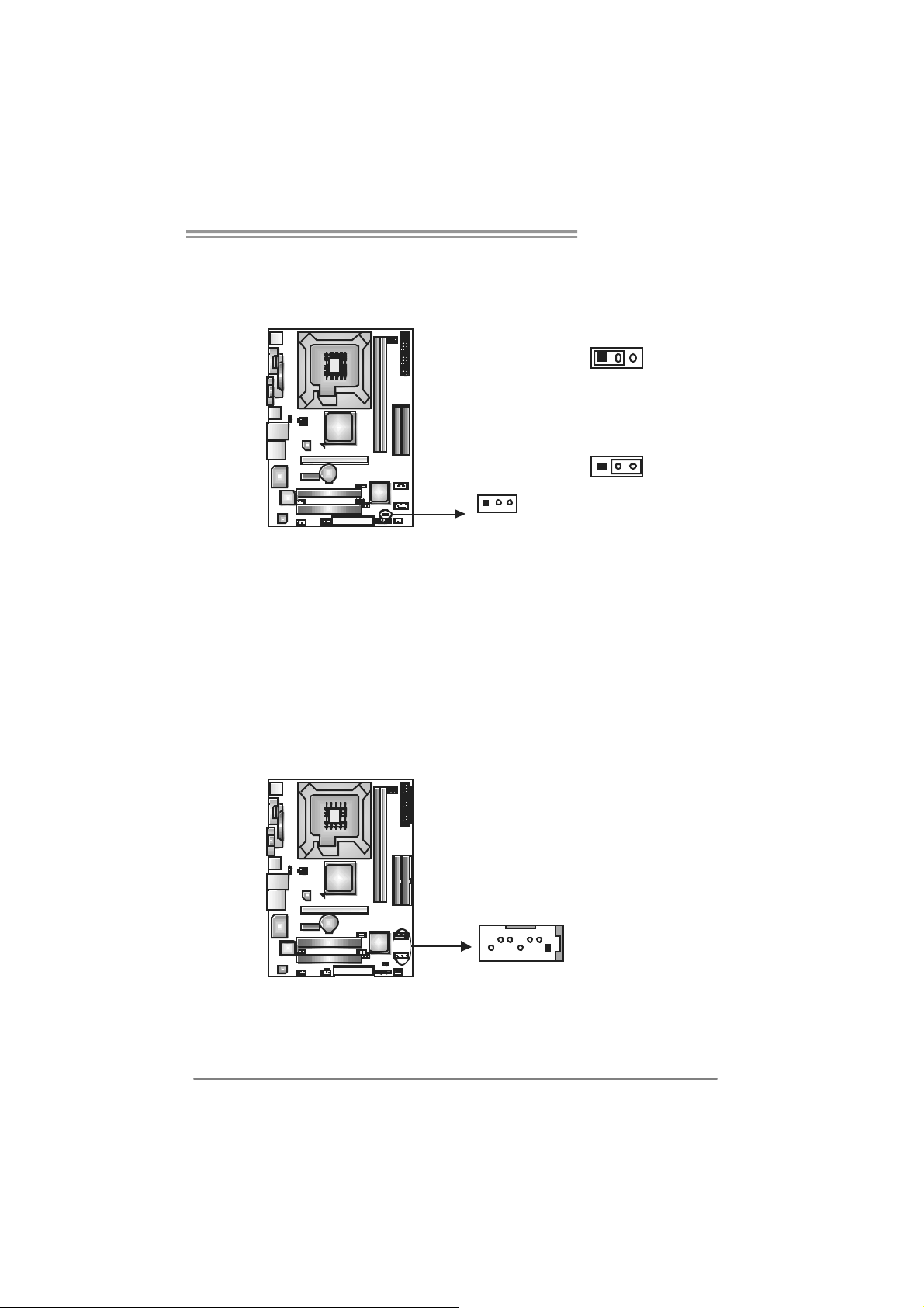
JCMOS 1 : C lear CMOS H eader
By pl ac i ng the jum per on pin2-3, it al lows user to rest ore the BI OS safe s ett i ng
and t he CMOS data, please caref ul ly foll ow t he procedures to av oi d damaging
t he m otherboard.
13
Pin 1-2 Close:
Normal Operation (default).
13
Pin 2-3 Close:
Clear CMOS data.
3
1
※ Clear CMOS Procedures:
1. Remove AC power line.
2. Set the jumper to “Pin 2-3 close”.
3. Wa it for fi ve se co n ds.
4. Set the jumper to “Pin 1-2 close”.
5. Power on the AC.
6. Res et your desired pas sword or cl ear the CMOS data.
JSATA1~ JS ATA2 : Serial ATA Connecto rs
The motherboar d has a PCI t o SATA Contr ol ler with 2 channels SATA i nterface,
it satisfies the SATA 1.0 spec and with transfer rate of 1.5Gb/s.
Pin
Assignment
1 Ground
2 TX+
3 TX4 Ground
5 RX-
JSATA2
6 RX+
7 Ground
7
14
JSATA1
19
Motherboard Manual
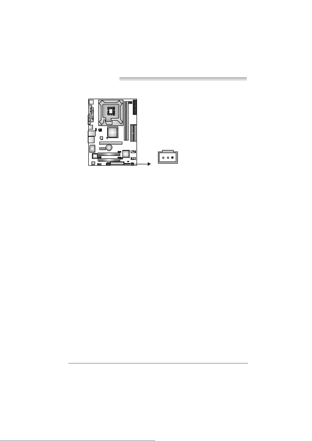
JS PDIF_O U T1: Digital Audio-out Connector
This c onnect or al l ows user t o connect the PCI bracket SPDIF output header.
Pin
Assignment
1 +5V
2 SPDIF_OUT
3 Ground
13
20
CHAPTER 4: USEFUL HELP
4.1 DRIVER INSTALL ATION NOTE
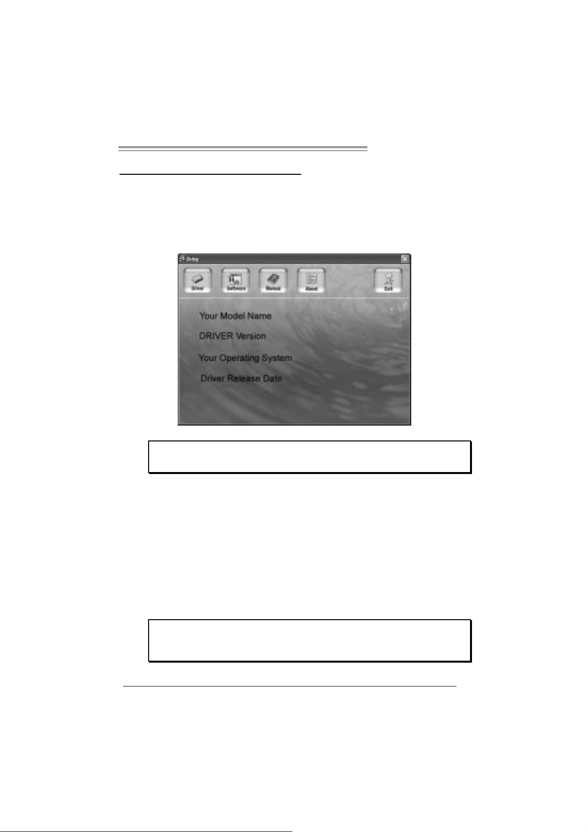
After you installed your operating system, please insert the Fully Setup
Driver CD into your optical drive and install the driver for better system
performance.
You will see the following window after you insert the CD
P4M900 Micro 775
The setup guide will auto detect your motherboard and operating system.
Note:
If this window didn’t show up after you ins ert the Driver CD, please use file browser to
l oc ate an d execu te t he fi le SETU P.E XE under yo ur opt i c al dri ve .
A. Driver Installation
To install the driver, please click on the Driver icon. The setup guide will
list the compatible driver for your motherboard and operating system.
Click on each device driver to launch the installation program.
B. Software Installation
To install the software, please click on the Software icon. The setup guide
will list the software available for your system, click on each software title
to launc h the ins ta llat ion pr ogra m.
C. Manual
Aside from the paperback manual, we also provide manual in the Driver
CD. Click on the Manual icon to browse for available manual.
Note:
You will need Acrobat Re ade r to open t he man ual file . Plea se download the la te s t ve rs ion
of A crobat Reader software from
http://www.adobe.com/products/acrobat/readstep2.html
21
Motherboard Manual
4.2 AWARD BIOS BEEP CODE
Beep Sound Meanin g
One long beep f ol l owed by two short
beeps
High- l ow sir en sound CPU ov erheated
One Short beep when system boot-up No err or found duri ng POST
Long beeps every other sec ond No DRAM detected or instal l
Video c ard not found or video card
memory bad
Syst em will shut down automat ically
4.3 EXT RA INFORMATION
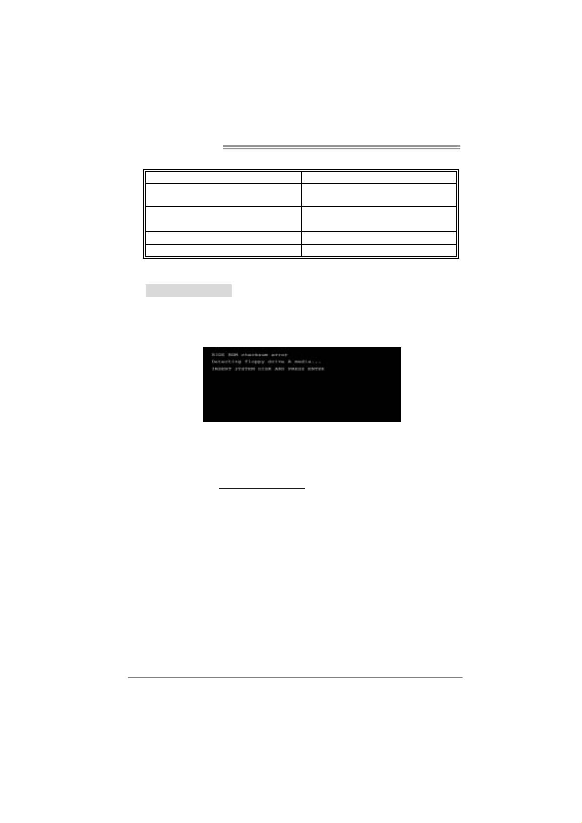
A. BIOS Update
After you fail to update BIOS or BIOS is invaded by virus, the
Boot-Block function will help to restore BIOS. If the following message
is shown after boot-up the system, it means the BIOS contents are
corrupted.
In this Case, please follow the procedure below to restore the BIOS:
1. Mak e a bo ot ab le flop py dis k.
2. Download the Flash Utility “AWDFLASH.exe” from the Biostar
website: www.biostar.com.tw
3. Confirm motherboard model and download the respectively BIOS
from B ios tar website.
4. Copy “AWDFLASH.exe” and respectively BIOS into floppy disk.
5. Insert the bootable disk into floppy drive and press Enter.
6. System will boot-up to DOS prompt.
7. Type
“Aw dfla sh xxxx.bf / sn/p y/ r” in DOS prompt.
(
xxxx means BIOS name.)
8. System will update BIOS automatically and restart.
9. The BIOS has been recovered and will work properly.
22

P4M900 Micro 775
B. CPU Overheated
If the system shutdown automatically after power on system for
seconds, that means the CPU protection function has been activated.
When the CPU is over heated, the motherboard will shutdown
automatically to avoid a damage of the CPU, and the system may not
power on again.
In this case, please double check:
1. The CPU cooler surface is placed evenly with the CPU surface.
2. CPU fan is rotated normally.
3. CPU fan speed is fulfilling with the CPU speed.
After confirmed, please follow steps below to relief the CPU protection
function.
1. Remove the power cord from power supply for seconds.
2. Wai t for seconds.
3. Plug in the power cord and boot up the system.
Or you can:
1. Clear the CMOS data.
(See “Close CMOS Header: JCMOS1” section)
2. Wai t for seconds.
3. Power on the system again.
23
Motherboard Manual
e
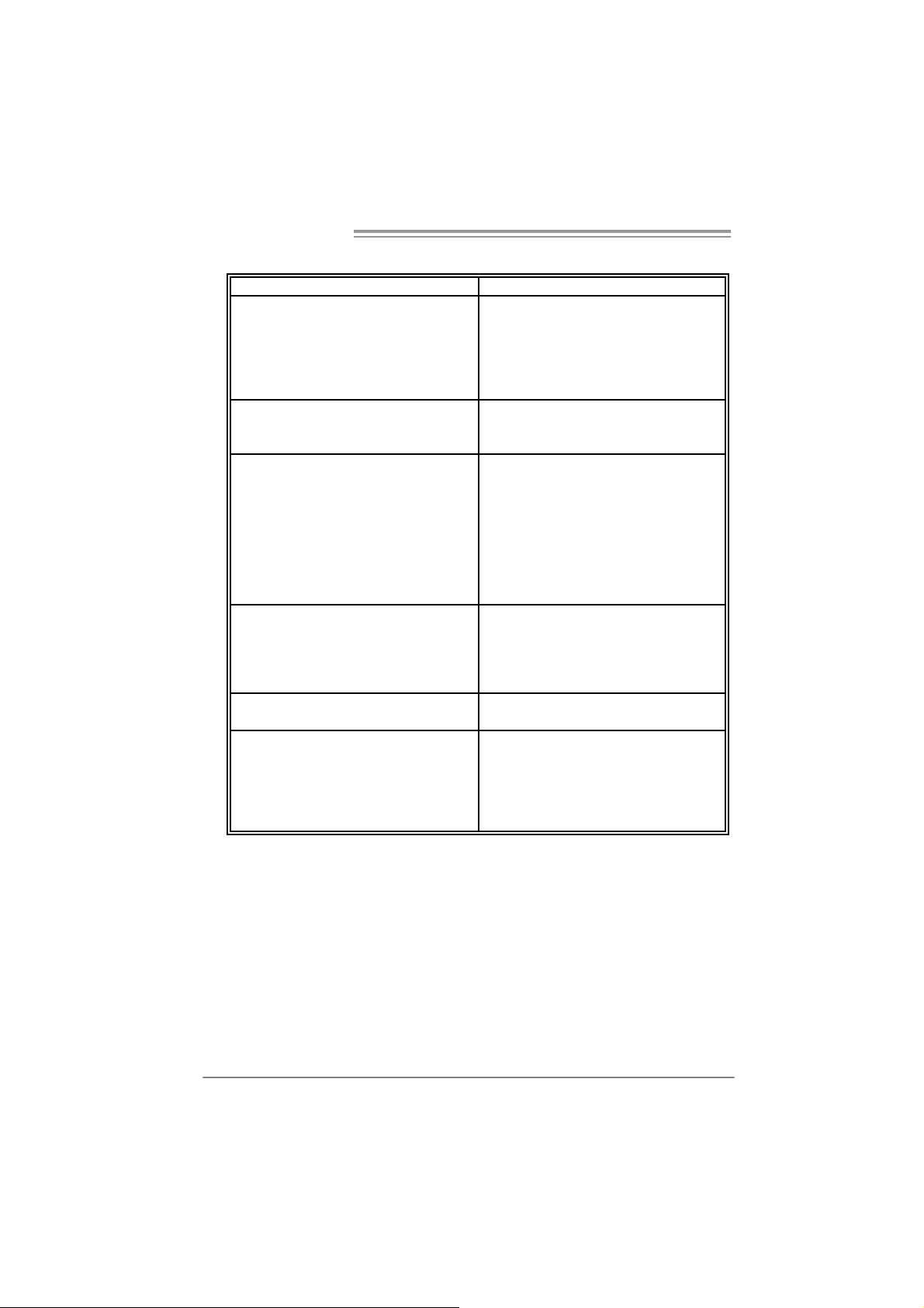
4.4 TROUBLESHOOTING
Probable Solution
1. No power t o the system at all
Power l ight don’t illuminate, fan
ins i de power supply does not turn
on.
2. I ndi cator light on keyboard does
not turn on.
System inoperat ive. Key board l i ghts
are on, power indicat or lights are lit,
and hard drive is s pi nning.
System does not boot from hard disk
drive, c an be booted from opti cal drive.
System only boots f rom optical drive.
Hard di sk can be read and appli cations
can be used but booting from hard disk
is impossi ble.
Screen m ess age says “I nvali d
Configur ati on” or “CMOS Failure.”
Cannot boot sys tem after installing
second hard drive.
1. Make sur e power cabl e is
securely plugged i n.
2. Replace cable.
3. Contact technical support.
Us i ng even pres sure on both ends of
t he DIMM, pr ess down fi rm ly until the
module snaps int o pl ace.
1. Check cabl e running fr om disk t o
dis k contr ol ler board. Make sure
bot h ends are secur ely plugged
in; check t he driv e ty pe in the
standard CMOS setup.
2. Backi ng up the hard drive is
extr em ely important. All hard
dis ks are capabl e of breaking
down at any time.
1. Back up data and applicat i ons
files.
2. Refor m at t he har d drive.
Re-i nstall applic ations and dat a
usi ng backup disks.
Rev i ew system’s equipment . Make s ur
correct informat ion is in setup.
1. Set m ast er/s l ave jumper s
correctly.
2. Run SETUP program and select
cor rect drive types. Call the drive
manu facturers for compatibili ty
with other dr ives.
24

P4M900 Micro 775
CHAPTER 5: WARPSPEEDER™
5.1 INTRODUCTION
[WarpSpeeder™], a new powerful control utility, features three
user-friendly functions including Overclock Manager, Overvoltage
Manager, and Hardware Monitor.
With the Overclock Manager, users can easily adjust the frequency they
prefer or they can get the best CPU performance with just one click. The
Overvoltage Manager, o n the other hand, helps to power up CPU core
vol tag e an d Me mory v olta ge. Th e co o l Har dw ar e Mo ni tor s mar t ly in d icat es
the temperatures, voltage and CPU fan speed as well as the chipset
information. Also, in the About panel, you can get detail descriptions about
BIOS model and chipsets. In addition, the frequency status of CPU,
memory, AGP and PCI along with the CPU speed are synchronically
s how n on our ma i n pan el .
Moreover, to protect users' computer systems if the setting is not
appropriate when testing and results in system fail or hang,
[WarpSpeeder™] technology assures the system stability by automatically
rebooting the computer and then restart to a speed that is either the
original system speed or a suitable one.
5.2 SYSTEM REQUI REMENT
OS Support: Windows 98 SE, Windows Me, Windows 2000, Windows XP
DirectX: DirectX 8.1 or above. (The Windows XP operating system
includes DirectX 8.1. If you use Windows XP, you do not need to install
D irec tX 8. 1.)
25
Motherboard Manual
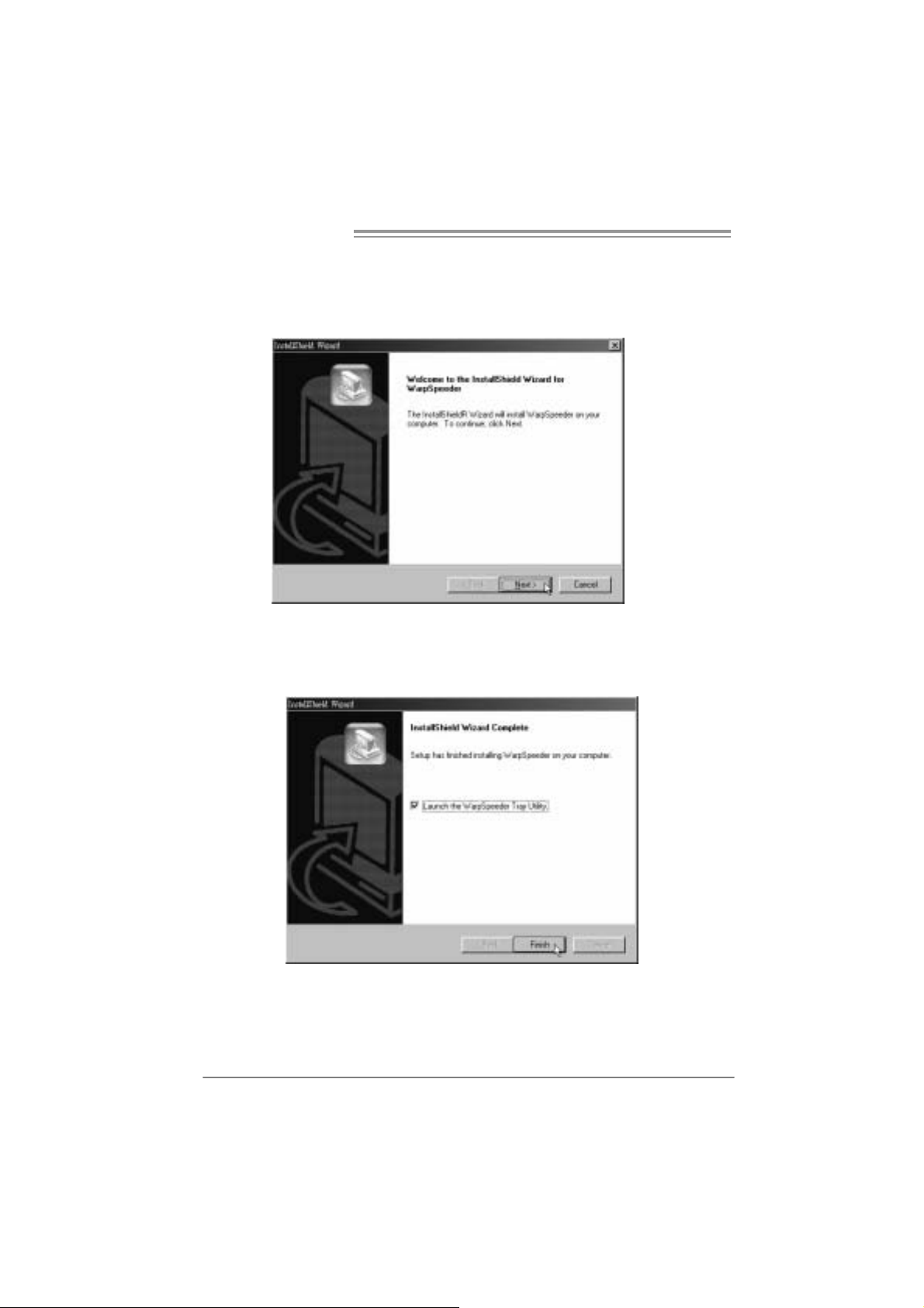
5.3 INSTALLATION
1. Execute the setup execution file, and then the following dialog will pop
up. Please click “Next” button and follow the default procedure to
install.
2. When you see the following dialog in setup procedure, it means setup
is completed. If the “Launch the WarpSpeeder Tray Utility” checkbox
is checked, the Tray Icon utility and [WarpSpeeder™] utility will be
automatically and immediately launched after you click “Finish”
button.
Usage:
The following figures are just only for reference, the screen printed in
this user manual will change according to your motherboard on hand.
26
5.4 WARPSPEEDER™
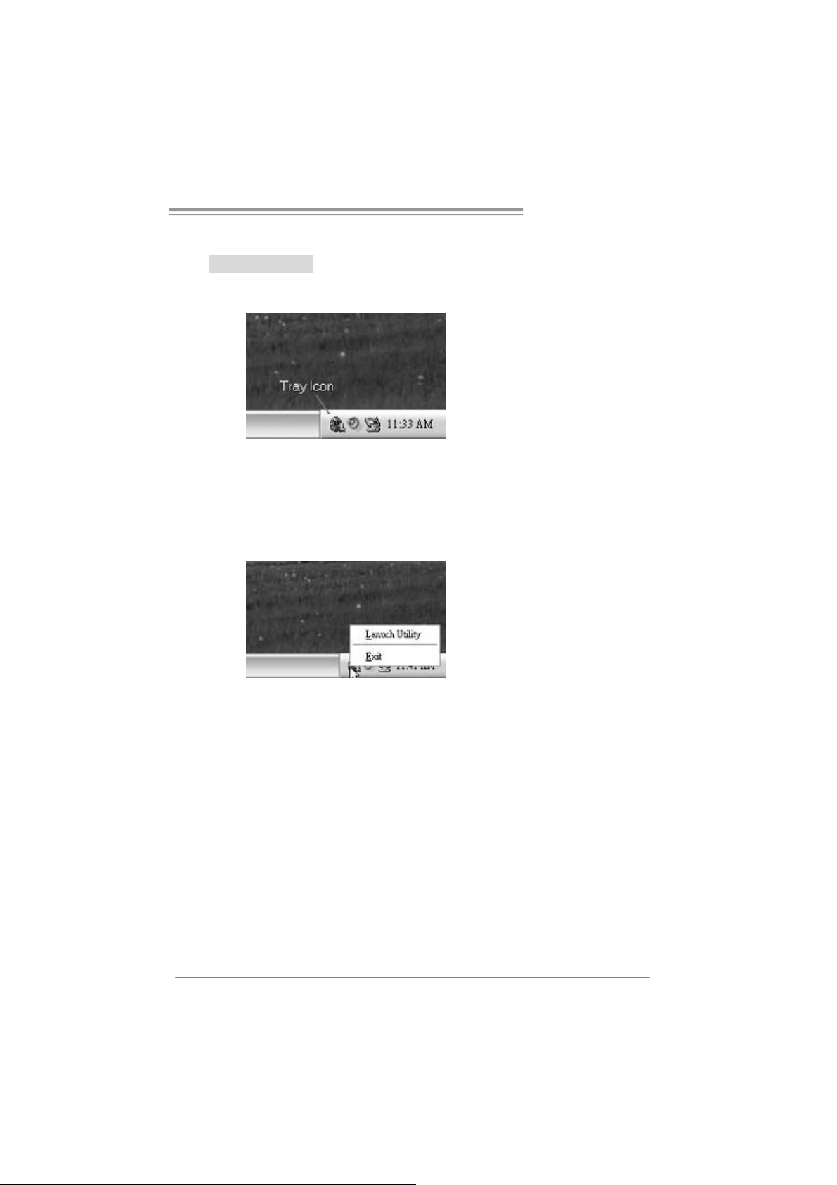
1. Tray Icon:
Whenever the Tray Icon utility is launched, it will display a little tray
icon on the righ t side of Windows Taskbar.
This utility is responsible for conveniently invoking [WarpSpeeder™]
Utility. You can use the mouse by clicking the left button in order to
invoke [WarpSpeeder™] directly from the little tray icon or you can
right-click the little tray icon to pop up a popup menu as following
figure. The “Launch Utility” item in the popup menu has the same
function as mouse left-click on tray icon and “Exit” item will close
Tray Icon utility if selected.
P4M900 Micro 775
27
Motherboard Manual
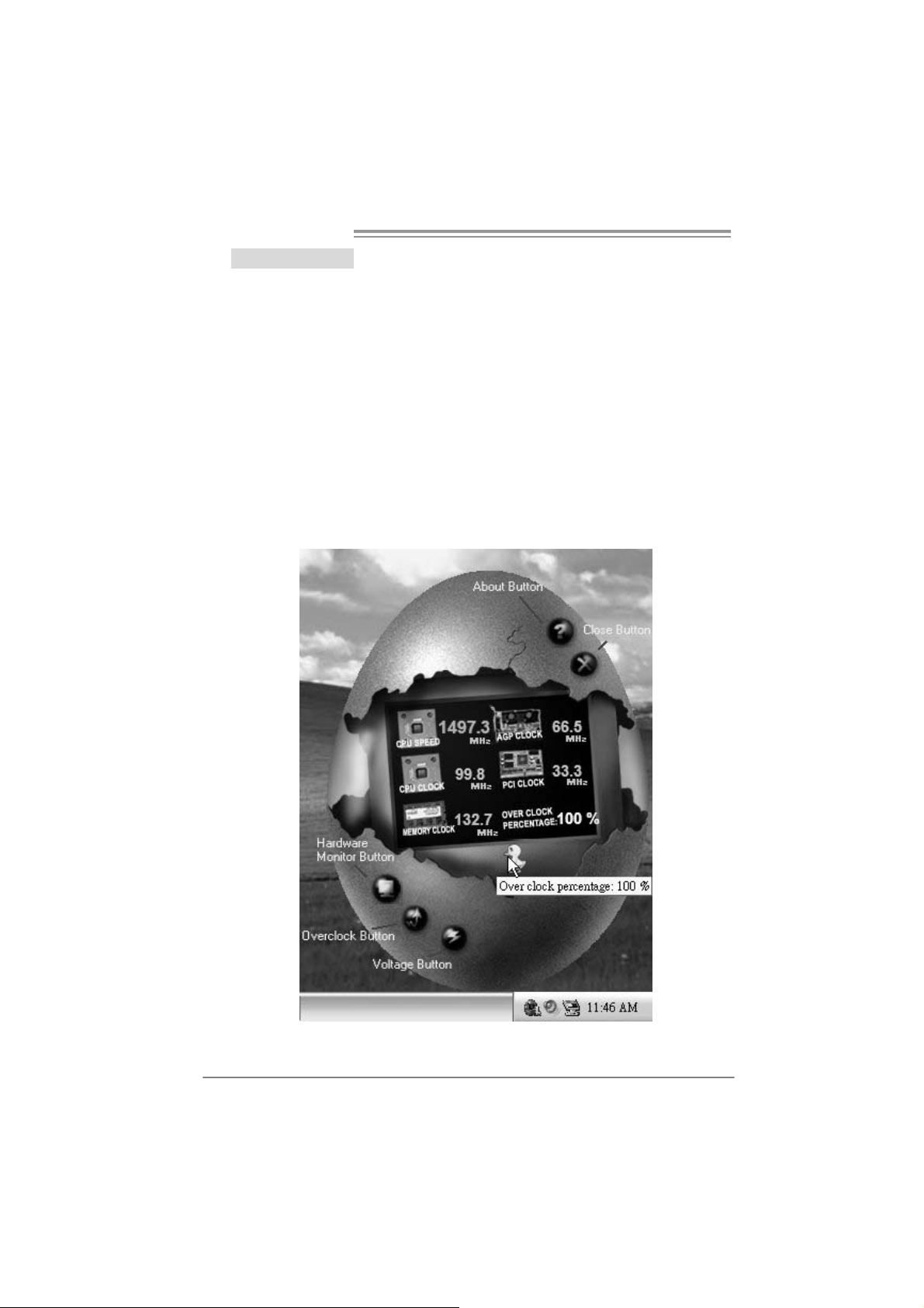
2. Main Panel
If you click the tray icon, [WarpSpeeder™] utility will be invoked.
Please refer to the following figure; the utility’s first window you will
see is Main Panel.
Main Panel contains features as foll ows:
a. Di splay the CPU Speed, CPU external cl ock, Memory clock, AGP cl ock,
and PCI clock information.
b. Contains About, Voltage, Overclock, and Hardware Monitor Buttons for
invoking respective panels.
c. W ith a us er- frie nd ly St atus An im atio n, it c an r epr es ent 3 ov erc lock
percentage stages:
Man walking
Panther running
Car racing
→overclock percentage from 100% ~ 110 %
→overclock percentage from 110% ~ 120%
→overclock percentage from 120% ~ above
28
 Loading...