

Page 1

P43-A7/ P45D2 - A7 BIOS Manual
i
B IOS Set up.... ............ ............ ............ ............ ............ ............ ............ .........1
1 Main Menu...............................................................................................3
2 Adv anc ed Menu...... ............ ............ ............ ............ ............ ............ .........8
3 PCIPnP Menu........................................................................................20
4 Boot Menu..............................................................................................23
5 C hipset Menu.........................................................................................26
6 Perform a nce Men u...............................................................................3 0
7 Exit Menu...............................................................................................34
Page 2

P43-A7/ P45D2 - A7 BIOS Manual
BIOS Setup
Introduction
The purpose of this manual is to describe the settings in the AMI BIOS Setup
program on this motherboard. The Setup program allows users to modify the basic
system configuration and save these settings to CMOS R AM. T he power of CMOS
RAM is supplied by a battery so that it retains the S etup information when the power
is turned off.
Basic Input-Output System (BIOS) determines what a computer can do without
accessing programs from a disk. This system controls most of the input and output
devices such as keyboard, mouse, serial ports and disk drives. BIOS activates at the
first stag e o f the booting process, loading and executing the operating system. Som e
additional features, such as virus and password protection or chipset fine-tuning
options are also included in BIOS .
T he rest of this manual will to guide you through the options and settings in BIOS
Setup.
Plug and Play Support
T his AM I BIOS supports the Plug and Play Version 1. 0A specific ation.
EPA Green PC Support
T his AM I BIOS supports Version 1.03 of the EPA Green PC specification.
ACPI Support
AMI ACPI BIOS support Version 1.0/2.0 of Advanced Configuration and Power
interface specifi cation (ACP I). It provides ASL code for power management and
device configuration capabilities as defined in the ACPI specification, developed by
Microso ft, Intel and T oshiba.
1
Page 3
P43-A7/ P45D2 - A7 BIOS Manual
PCI Bus Support
T his AMI BIOS also supports Version 2.3 of the Intel PCI (Peripheral Component
Int erconn ect ) local b u s s p eci fi cati o n.
DRA M Support
DDR2 S DRAM (Double Data Rate II S ynchronous DR AM) is supported.
Su ppor t e d CP Us
T his AM I BIOS supports the Int el CP U.
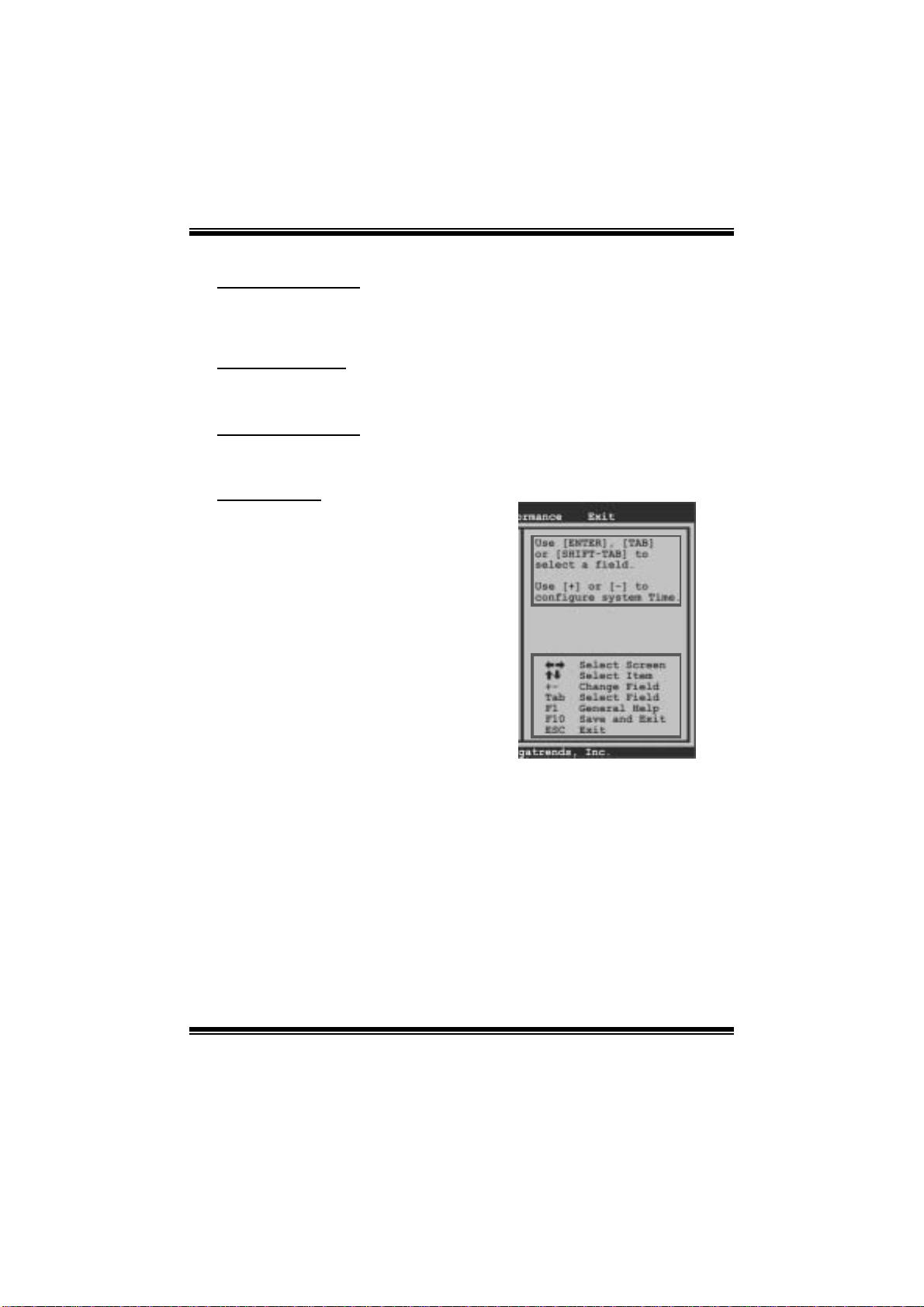
Using Setup
When starting up the computer, press
<Del> during the Power-On Self-Test
(POST) to enter the BIOS setup utility.
In the BIOS setup utility, you will see
General Help description at the top right
corner, and this is providing a brief
description of the selected item.
Navigation Keys for that particular menu
are at t he bottom right corner, and you can
us e thes e keys to select i tem an d ch ange
the settings.
Notice
z T he default BIOS settings apply for most conditions to ensure optimum performance
of the motherboard. If the system becomes unstable after changing any settings,
please load the default settings to ensure system’s compatibility and stability. Use
Load S etup Default under the Exit Menu.
z For better system perform ance, the BIOS firmwa re is being continuously updated.
T he BIOS information described in this manual is for your refer ence only. The actual
BIOS information and settings on board may be slightly differ ent from this manual.
z T he content of this manual is subject to be chang ed without notice. We will not be
responsible for any mi stakes found in this user’s manual and any system damage that
may be caused by wrong-settings.
General Help
Navigation Keys
2
Page 4
P43-A7/ P45D2 - A7 BIOS Manual
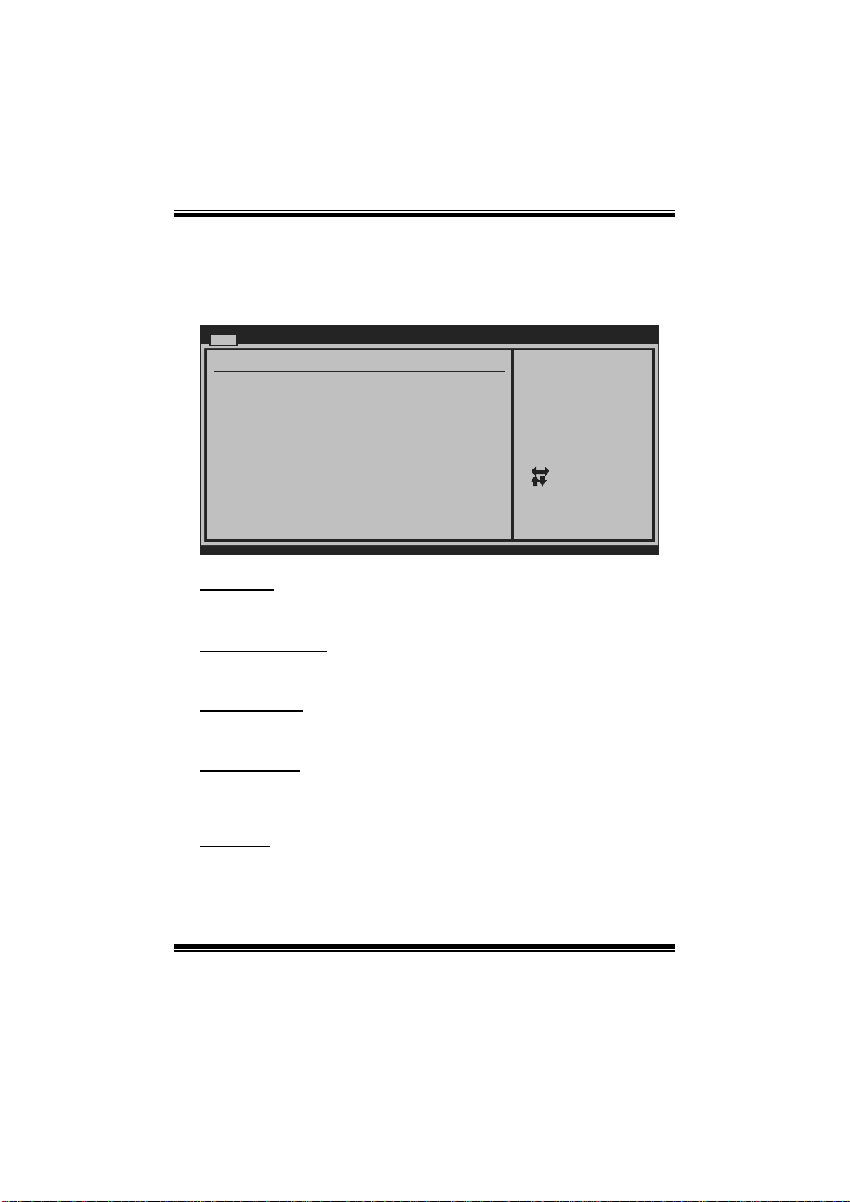
1 Main Men u
Once you enter AMI BIOS Setup Utility, the Main Menu will appear on the screen
providing an overview of the basic system inform ation.
Main Advanc ed PCIPnP Boot Chipset Performance
System Overview
AMI BIOS
Version :01.0 1.01
Build Date:01/0 1/08
System Memory
Size :
BIOS SETUP UTILITY
Use [ENTER], [TAB]
or [SHIFT-TAB] to
select a field.
Use [+] or [-] to
configure system Time.
Exit
System Time 00
System Date [Tue 01/01/2008]
Floppy A
> IDE/SATA Conf iguration
vxx. xx (C)Copyright 1985-200x, American Megatrends, Inc.
[ :00:00]
Select Screen
Select Item
Change Field
+-
Select Field
Tab
General Help
F1
Save and Exit
F10
Exit
ESC
AM I BIO S
Shows sys tem information including BIOS version, built date, etc.
System Memory
Shows sys tem memory size, VGA shard memory wil l be excluded..
System Time
Set the system internal clock.
System Date
Set the system date. Note that the ‘Day’ automatically changes when you set the
date.
Floppy A
Select the type of floppy disk drive installed in your system.
Options: 360K, 5 1/4 i n / 1.2M, 5 1/4 in / 720K, 3 1/2 in / 1.44M , 3 1/ 2 in /
2.88M, 3 1/2 in / Disabled
3
Page 5

P43-A7/ P45D2 - A7 BIOS Manual
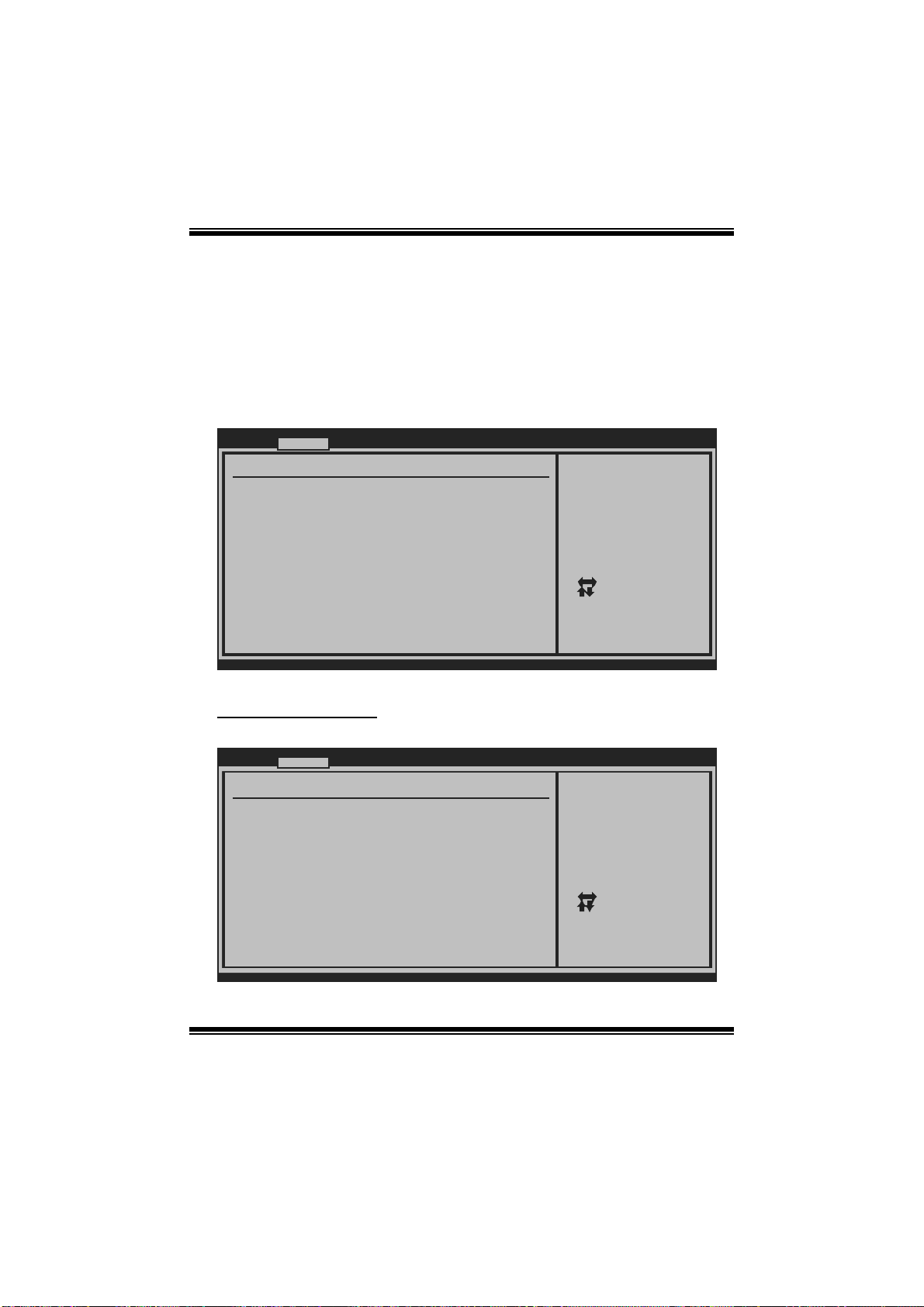
IDE/SAT A C onfig uration
Th e BIOS w i ll au t o m ati cal l y detect t h e presen c e o f ID E / SAT A d evices . T here is a
su b-menu fo r each IDE/S AT A device. S elect a devi ce an d pres s <Enter> t o ent er
the sub-menu of detailed opti ons.
Main
IDE/SATA Confug uration
SATA#1 Configur ation [Com patible]
Configure SAT A#1 as [IDE ]
Max Ports on SATA#1 [6 P orts]
SATA#2 Configur ation [Enh anced]
> AHCI Configur ation
> SATA 1 Device
> SATA 2 Device
> SATA 3 Device
> SATA 4 Device
> SATA 5 Device
> SATA 6 Device
> Primary IDE M aster
> Primary IDE S lave
Hot Plug [Dis abled]
Hard Disk Write Protect [Dis abled]
IDE Detect Time Out (Sec) [35]
vxx. xx (C)Copyright 1985-200x, American Megatrends, Inc.
SATA# 1 Configura tion
BIOS SETUP UTILITY
Options
Disabled
Compatible
Enhanced
Select Screen
Select Item
Go to Sub Screen
Enter
General Help
F1
Save and Exit
F10
Exit
ESC
T his i tem allows you to control the onboard SAT A controller.
Options: Compatible (Default) / Disabled / Enhanced
Configure SATA#1 as
T his i tem allows you to choose the SAT A operati on m ode.
Opt i ons : IDE (De fau lt) / AH CI
Max Ports on SATA#1
T his item appears only when SAT A mode is set to AHCI/RAID.
Options: 6 Ports (Default) / 4 P orts
SATA# 2 Configura tion
T his i tem allows you to control the onboard SAT A controller.
Options: Enhanced (De fault) / Disabled
4
Page 6

P43-A7/ P45D2 - A7 BIOS Manual
AHCI Configuration
Main
AHCI Settings
AHCI BIOS Suppo rt [Ena bled]
AHCI CD\DVD Boo t Time out [35]
> AHCI Port0
> AHCI Port1
> AHCI Port2
> AHCI Port3
> AHCI Port4
> AHCI Port5
vxx. xx (C)Copyright 1985-200x, American Megatrends, Inc.
BIOS SETUP UTILITY
Enables for supporting
Select Screen
Select Item
Change Option
+-
General Help
F1
Save and Exit
F10
Exit
ESC
AHC I BIOS Support
T his B IOS feature controls the AHCI function of the SAT A controller.
Options: Enabled (Default) / Disabled
AHC I CD / D VD Boo t T ime Out
T his B IOS feature allows you to set the AHCI CD/DVD boot time out.
Options: 35 (Default) / 0 / 5 / 10 / 15 / 20 / 25 / 30
AH CI Port0/ Port 1/Po rt2/ Port 3/ Port4/Port5
Main
AHCI Port0
Device :
SATA Port0 [Auto]
S.M.A.R.T. [Enable d]
BIOS SETUP UTILITY
Select the type
of device connected
to the system.
Select Screen
Select Item
Change Option
+-
General Help
F1
Save and Exit
F10
Exit
ESC
vxx. xx (C)Copyright 1985-200x, American Megatrends, Inc.
5
Page 7

P43-A7/ P45D2 - A7 BIOS Manual
D evice
This area shows the detected connected device.
SATA Port0/ 1/2/3/ 4/5
This item allows you to select the connected device type.
Options: Auto (Default)
S.M.A.R.T.
This item allows you to control the device S. M.A. R.T function.
Options: Enabled (Default) / Disabled
SATA 1/2/3/4/5/6 Device; Primary IDE Master/Slave
Main
SATA 1 Device
Device :
Type [Aut o]
LBA/Large Mode [Aut o]
Block (Multi-Se ctor Transfer)[Aut o]
PIO Mode [Aut o]
DMA Mode [Aut o]
S.M.A.R.T [Aut o]
32Bit Data Tran sfer [Ena bled]
vxx. xx (C)Copyright 1985-200x, American Megatrends, Inc.
BIOS SETUP UTILITY
Select the type
of device connected
to the system.
Select Screen
Select Item
Change Option
+-
General Help
F1
Save and Exit
F10
Exit
ESC
The BIOS detects the information and values of resp ective devices, and these
information and values are shown below t o the nam e of the sub-menu.
Type
Select the type of the IDE/SATA drive.
Options: Auto (Default) / C DROM / ARMD / Not Installed
LBA/Large Mode
Enabl e or dis able the LB A mode.
Options: Auto (Default) / Disabled
Block (Multi-Sector Transfer)
En able o r d i s ab l e m u l ti- secto r t ransfer.
Options: Auto (Default) / Disabled
6
Page 8

P43-A7/ P45D2 - A7 BIOS Manual
PIO Mode
Select the PIO m ode.
Options: Auto (Default) / 0 / 1 / 2 / 3 / 4
DMA Mode
Select the DMA mode.
Options: Auto (Default) / Disabled
S.M.A.R.T
Set the Smart Moni toring, Analysis, and Reporting Technol ogy.
Options: Auto (Default) / Disabled / Enabled
32Bit Data Transfer
Enabl e or dis able 32-bit data transfer.
Options: Enabled (Default) / Disabled
Hot Plug
This item allows you to control the device Hot-Plug function. The Hot-Plug
fun ction is only all owed i n AHCI mode.
Options: Disabled (De fault) / Enabled
Har d Disk Wri te Protect
Disable or enable device write protection. This will be effective only if the device
is accessed through BIOS .
Options: Disabled (De fault) / Enabled
IDE Detect Time Out (Sec)
Select the time out value for detecting IDE/S AT A devices.
Options: 35 (Default) / 30 / 25 / 20 / 15 / 10 / 5 / 0
7
Page 9
P43-A7/ P45D2 - A7 BIOS Manual
2 Advanced Menu
T he Advanced Menu allows you to configure the settings of CP U, Super I/O, P ower
Management, and other syst em devices.
Notice
z Beware of that setting inappropriate values in items of this menu may cause
system to m alfunction.
Main Advan ced PCIPnP Boot Chipset Performance
WARNING: Settin g wrong values in below sections
may ca use system to malf unction.
> CPU Configura tion
> SuperIO Confi guration
> Hardware Heal th Configuration
> Smart Fan Con figuration
> PM/ACPI Confi guration
> USB Configura tion
> Config Onboar d PCI/PCI-E Device s
BIOS SETUP UTILITY
Configure CPU.Advanced Settin gs
Exit
Select Screen
Select Item
Go to Sub Screen
Enter
General Help
F1
Save and Exit
F10
Exit
ESC
vxx. xx (C)Copyright 1985-200x, American Megatrends, Inc.
CPU Configurati on
T his item shows the C PU information that the BIOS automatically detects.
Advanc ed
Configure advan ced CPU settings
Module Version: 3F.09
Manufacturer:In tel
Frequency :
FSB Speed :
Cache L1 :
Cache L2 :
Ratio Status:
Ratio Actual Va lue:
C1E Support [En abled]
Hardware Prefet cher [En abled]
Adjacent Cache Line Prefetch [En abled]
Max CPUID Value Limit [Di sabled]
Intel(R) Virtua lization Tech [En abled]
CPU TM function : [Di sabled]
Execute-Disable Bit Capability[En abled]
Core Multi-Proc essing [En abled]
Intel(R) SpeedS tep(tm) tech [En abled]
vxx. xx (C)Copyright 1985-200x, American Megatrends, Inc.
BIOS SETUP UTILITY
8
This should be enabled
in order to enable or
disable the Enhanced
Halt State.
Select Screen
Select Item
Change Option
+-
General Help
F1
Save and Exit
F10
Exit
ESC
Page 10

P43-A7/ P45D2 - A7 BIOS Manual
C1E Support
C1E is “Enhanced Halt State” function, this function helps to save power and
decr ease he at by lowering CPU frequen cy while the processor is not working.
Options: Enabled (Default) / Disabled
Hardware Prefetcher
Th e proces s o r h as a h ard ware prefet ch er that au t om at i cal l y anal yzes it s req uirem en t s
and pre fet ch es dat a and i ns t r uct io ns fr om t h e m emor y i n t o th e L ev el 2 cach e t h at are
likely to be required in the near future. This reduces the latency associated with
m emory read s.
Options: Enabled (Default) / Disabled
Adj acent Cache Line Prefetch
The processor has a hardware adjacent cache line prefetch mechanism that
aut o mat i cal l y fet ch es an ex t ra 64-b y t e cach e l i n e whenever t h e p rocess or request s for
a 64-byte cache line. This reduces cache latency by making the next cache line
immediately available if the processor requir es it as well.
Options: Enabled (Default) / Disabled
M ax CPUI D Va l ue Li m i t
When the computer is booted up, the operating system executes the CPUID
instruction to identify the processor and its capabilities. Befo re it can do so, it must
first query the processor to find out the highest input value CPUID recognizes. T his
determines the kind of basic information C PUID can provide the operati ng system.
Options: Disabled (De fault) / Enabled
Inte l(R) Virtualization Tec h
Virtualization Technology can virtually separ ate your system resou rce into several
parts, thus enhance the performance when running virtual machines or multi
interface systems.
Options: Enabled (Default) / Disabled
CPU TM Function
The CP U T M Function is to throttle the clock speed o f higher spe ed Prescott's to
hel p keep t h em coo l .
Options: Disabled (De fault) / Enabled
9
Page 11

P43-A7/ P45D2 - A7 BIOS Manual
Execute-Disable Bit Capability
T his i tem allows you to configure the Execut e Disabled Bit function, which protects
your system from buffer over flow attacks.
Options: Enabled (Default) / Disabled
Core Multi-Proce ssing
T his item allows multi-processing fun ction for multi-cor e processors.
Options: Enabled (Default) / Disabled
In tel(R) SpeedStep(tm) Tech
This item allows you to enable SpeedStep technology for better power saving.
SpeedStep is a technology built into some Intel processors that allows the clock
sp eed of the proces s o r to b e d y nami cal l y chang ed by s o ftware.
Options: Enabled (Default) / Disabled
S uperI O Co n f i g urat i o n
Advanc ed
Configure Super IO Chipset
Onboard Floppy Controller [En abled]
Serial Port1 Ad dress [3F 8/IRQ4]
Parallel Port A ddress [37 8]
Parallel Port Mode [No rmal]
Parallel Port IRQ [IR Q7]
Keyboard PowerO n [Di sabled]
Mouse PowerOn [Di sabled]
Restore on AC P ower Loss by IO[Po wer Off]
BIOS SETUP UTILITY
Allows BIOS to Enable
or Disable Floppy
Controller
Select Screen
Select Item
Change Option
+-
General Help
F1
Save and Exit
F10
Exit
ESC
vxx. xx (C)Copyright 1985-200x, American Megatrends, Inc.
Onboard Floppy Controlle r
Select enabled if your system has a floppy disk controller (FDC) installed on the
system board and you wish to use it. If you ins talled another FDC or the system uses
no floppy drive, select disabled in this field.
Options: Enabled (Default) / Disabled
10
Page 12

P43-A7/ P45D2 - A7 BIOS Manual
Serial Port1 Address
Select an address and corresponding interrupt for the fi rst and second serial ports.
Options: 3F8/IR Q4 (Default) / 2F8/IRQ3 / 3E8/IRQ4 / 2E8/IRQ3 / Auto / Disabled
Parallel Port Address
Th i s i t em al l ows yo u to det ermine acces s onboard parall el port controller with which
I/O Address.
Options: 378 (Default) / 278 / 3BC / Dis abled
Parallel Port M ode
T his i tem allows you to determine how the parallel port should function.
Options: Normal (Default) Using Parallel port as S tandard Printer Port.
EPP Using Parallel Port as Enhanced Parallel Port.
ECP Using Parallel port as Extended Capabilities Port.
ECP + EPP Using Parallel port as ECP & EPP mode.
Parallel Port IRQ
T his i tem allows you to select the IR Q for the onboard paral lel port.
Options: IRQ7 (Default) / IRQ5 / Disabled
Keyboard PowerO n
T his i tem allows you to control the keyboard power on function.
Options: Disabled (De fault) / Enabled
Mouse PowerOn
T his i tem allows you to control the mouse power on function.
Options: Disabled (De fault) / Enabled
Restore on AC Power Loss by IO
T his s etting specifies how your system should behave a fte r a power fail or interrupts
occurs. By choosing Disabled will leave the computer in the power off state.
Choosing Enabled will restore the system to the status before power failure or
interrupt occurs.
Options: Power Off (Default) / Power ON / Last State
11
Page 13

P43-A7/ P45D2 - A7 BIOS Manual
Hardware Health C onfiguration
T his i tem shows t he system temperature, fan speed, and voltage information.
Advanc ed
Hardware Health Configuration
H/W Health Func tion [Ena bled]
Shutdown Temper ature [Dis abled]
CPU Temperature
System Temperat ure
CPU Fan Speed
JSFAN1 Speed
CPU Voltage
NB/SB Voltage
+3.30V
+5.00V
+12.0V
FSB Voltage
DDR2 Voltage
5VSB
VBAT
BIOS SETUP UTILITY
Enables Hardware
Health Monitoring
Device.
Select Screen
Select Item
Change Option
+-
General Help
F1
Save and Exit
F10
Exit
ESC
vxx. xx (C)Copyright 1985-200x, American Megatrends, Inc.
H/W Health Function
If you computer contains a monitoring system, it will show PC health status during
P OST s t ag e.
Options: Enabled (Default) / Disabled
Shutdown Tem perature
T his item allows you to set up the CPU shutdown T emperature. This item is only
effective under W indows 98 ACPI mode.
Options: Disabled (Default) / 60℃/140℉ / 6 5℃/149℉ / 70 ℃/158℉ / 7 5 ℃/167℉
/ 80℃/176℉ / 85℃/185℉ / 90 ℃/194℉
12
Page 14

P43-A7/ P45D2 - A7 BIOS Manual
Smart Fan Configuration
Advanc ed
Smart Fan Confi guration
CPU Smart Fan [Dis abled]
Smart Fan Calib ration
Control Mode
Fan Ctrl OFF( C )
Fan Ctrl On(C)
Fan Ctrl Start value
Fan Ctrl Sensit ive
o
o
BIOS SETUP UTILITY
When you choice [Auto]
,[3Pin] or [4Pin],
please run the
calibration to define
the Fan parameters for
Smart Fan control
Select Screen
Select Item
Change Option
+-
General Help
F1
Save and Exit
F10
Exit
ESC
vxx. xx (C)Copyright 1985-200x, American Megatrends, Inc.
CPU S m art Fa n
This item allows you to contr ol the CPU Smar t Fan function.
Options: Disabled (default) / Auto / 3Pin / 4Pin
Sm art Fan Ca l i bration
Choose this item and then the BIOS will auto test and detect the CPU/System fan
fun ctions and show CPU/System fan speed.
Control Mode
T his item provides several operation modes of the fan.
Options: Quiet / Performance / Manual
Fan Ctrl OFF (℃)
If the CP U/System T emperature is lower than the set value, FAN will turn off.
Options: 0~127 (℃)
Fan Ctrl On(℃ )
CPU/System fan starts to work under smart fan function when arrive this set value.
Options: 0~127 (℃)
13
Page 15

P43-A7/ P45D2 - A7 BIOS Manual
Fan Ctrl S tart Va l ue
When CPU/System temperature arrives to the set value, the CPU/System fan will
work under Smart Fan Function m ode.
Options: 0~127 (℃)
Fan Ctrl Sensitive
Increasi n g t h e valu e wil l rai s e t he sp eed of C P U / Sys t em fan.
Options: 1~127
PM /A CPI Co nfigur at ion
Advanc ed
PM/ACPI Configu ration
APIC ACPI SCI I RQ [Dis abled]
USB Device Wake up From S3/S4 [Dis abled]
High Performanc e Event Timer [Dis abled]
Resume On PME# [Dis abled]
Resume On RING [Dis abled]
Resume On RTC A larm [Dis abled]
RTC Alarm Date( Days)
RTC Alarm Time
Active State Po wer-Management[Dis abled]
Suspend mode [S1( POS)]
ACPI Version Fe atures [ACP I v1.0]
ACPI APIC suppo rt [Ena bled]
AMI OEMB table [Ena bled]
Headless mode [Dis abled]
BIOS SETUP UTILITY
Enable/Disable
APIC ACPI SCI IRQ.
Select Screen
Select Item
Change Option
+-
General Help
F1
Save and Exit
F10
Exit
ESC
vxx. xx (C)Copyright 1985-200x, American Megatrends, Inc.
APIC ACPI SCI IRQ
Options: Disabled (De fault) / Enabled
USB Device Wakeup from S3/S4
T his i tem allows you to enable or disabled the USB resume from S3/S4 function.
Options: Disabled (De fault) / Enabled
High P erformance Event Tim er
T his i tem allows you to enable or disabled the HPET.
Options: Disabled (De fault) / Enabled
14
Page 16

P43-A7/ P45D2 - A7 BIOS Manual
Resume On P ME#
W hen you select Enabled, a PME signal from PCI card returns the system t o F ull ON
state.
For this function to work, you may need a LAN add-on card which supports the
Wake on LAN function. Set the Wake on LAN (WOL) jumper on motherboard to
enab le if applicabl e.
Options: Disabled (De fault) / Enabled
Resume On Ri ng
T his i tem allows you control the wake on ring function.
Options: Disabled (De fault) / Enabled
Resume On RTC Alarm
When “ Enabled”, you can set the date and time at which the RT C (real-time clock)
alar m awakens th e s y s tem from Su s pen d mod e.
Options: Disabled (De fault) / Enabled
RTC Alar m Date (Days )
You can choose which date the syst em will boot up.
RTC Alarm Time
You can choose the system boot up time, input hour, minute and second to specify.
Note: If you h ave change the settin g, you must let the system boot up until it
go es to the o pera ti n g sys tem , befo re thi s functi on wi ll work.
Active State Po wer-Manage ment
This item sets the ASPM configuration for the PCI Express devices before the
operating system boot s. This function is for OS which does not support ASP M.
Options: Disabled (De fault) / Enabled
15
Page 17

P43-A7/ P45D2 - A7 BIOS Manual
Suspe nd m ode
T he item allows you to select the suspend t ype under the ACP I operating system.
Opt i ons : S 1 (P OS) (Defau l t ) Po wer o n Susp end
S3 (STR) Suspend to RAM
Auto POS+STR
ACPI Version Features
Th e item al l o ws yo u to sel ect t he vers i o n of ACPI.
Options: ACP I v1.0 (Default) / ACP I v2.0 / ACPI v3. 0
ACPI AP I C support
This item is used to enable or disable the motherboard's APIC (Advanced
Programmable Interrupt Controller). The APIC provides multiprocessor support,
more IRQs and faster interrupt handling.
Options: Enabled (Default) / Disabled
AMI OEMB tabl e
Set this value to allow the AC PI BIOS to add a pointer to an OEMB table in the R oot
Syst em Description Table (RSDT ) table.
Options: Enabled (Default) / Disabled
Headless mode
This is a server-specific feature. A headless server is one that operates without a
keyboard, monitor or mouse. To run in headless mode, both BIOS and operating
system (e.g. Windows Server 2003) must support headless operation.
Options: Disabled (De fault) / Enabled
16
Page 18

P43-A7/ P45D2 - A7 BIOS Manual
USB Configurati on
T his i tem shows t he USB controller and using USB device information.
Advanc ed
USB Configurati on
Module Version - 2.24.2-13.4
USB Devices Ena bled:
Legacy USB Supp ort [Ena bled]
USB 2.0 Control ler Mode [HiS peed]
BIOS EHCI Hand- Off [Ena bled]
> USB Mass Stor age Device Configu ration
BIOS SETUP UTILITY
Enables support for
legacy USB. AUTO
option disables
legacy support if
no USB devices are
connected.
Select Screen
Select Item
Change Option
+-
General Help
F1
Save and Exit
F10
Exit
ESC
vxx. xx (C)Copyright 1985-200x, American Megatrends, Inc.
Legacy USB Support
T his item determines if the BIOS should provide legacy support for USB devices
li ke the key board, mouse, and USB drive. T hi s is a useful fe ature when using su ch
USB devices with operating systems that do not natively support USB (e.g.
Micros o ft DOS or Windows NT).
Options: Enabled (Default) / Disabled
USB 2.0 Controller Mode
T his i tem allows you to select the operation mode of the USB 2. 0 controller.
Options: HiSpeed (De fault) USB 2. 0-480Mbps
FullSpeed USB 1.1-12Mbps
BIO S EHCI Hand-Off
This item allows you to enable support for operating systems without an EHCI
hand-o ff featur e.
Options: Enabled (Default) / Disabled
17
Page 19

P43-A7/ P45D2 - A7 BIOS Manual
US B Ma ss Sto rag e De vi ce C o n f ig urat i on
Advanced
USB Mass Storage Device Configuration
USB Mass Storage Reset Delay [20 Sec]
Device #
Emulation Type [Auto]
vxx.xx (C)Copyright 1985-200x, American Megatrends, Inc.
BIOS SETUP UTILITY
Number of seconds
POST waits for the
USB mass storage
device after start
unit command.
Select Screen
Select Item
Change Option
+-
General Help
F1
Save and Exit
F10
Exit
ESC
USB Mass Storage Reset Delay
T his i tem allows you to set the reset delay for USB mass storage device.
Op t i ons : 2 0 Sec (D e faul t ) / 1 0 S ec / 30 S ec / 4 0 Sec
E m ula ti o n T yp e
T his i tem allows you to select the em ulation type of the USB mass storage device.
Options: Auto (Default) / F loppy / Forced FDD / Hard Disk / C DROM
Config Onboard PCI/PCI- E Devices
Advanced
Onboard PCI/PCI-E Devices Configuration
Onboard PCIE PATA Cntlr [Auto]
Onboard PCIE Giga LAN [Auto]
Onboard LAN Boot ROM [Disabled]
MAC ID Information
BIOS SETUP U TILITY
Options
Auto
Enabled
Disabled
Select Screen
Select Item
+-
Change Option
F1
General Help
F10
Save and Exit
ESC
Exit
vxx.xx (C)Copyright 1985-200x, American Me gatrends, Inc.
18
Page 20

P43-A7/ P45D2 - A7 BIOS Manual
Onboard PCIE PATA Cntlr
T his i tem allows you to control the onboard PAT A controller.
Options: Auto (Default) / Enabled / Disabled
Onboard PCIE Gi ga LAN
T his i tem allows you to control the onboard LAN.
Options: Auto (Default) / Enabled / Disabled
Onboard LAN Boot Rom
T his i tem allows you to select the Onboard LAN Boot ROM.
Options: Disabled (De fault) / Enabled
MAC ID Information
T his item shows the LAN MAC ID.
19
Page 21

P43-A7/ P45D2 - A7 BIOS Manual
3 PCIPnP Menu
T his section describes configuring the PCI bus system. PCI, or Personal Computer
Interconnect, is a system which allows I/O devices to operate at speeds nearing the
speed of the CP U itself uses when communicating with its own special components.
Notice
z Beware of that setting inappropriate values in items of this menu may cause
system to m alfunction.
Main Advan ced PCIPnP Boot Chipset Performance
Advanced PCI/PnP Settings
WARNING: Setting wrong values in below sections
may cause system to malfunction.
Clear NVRAM [No]
Plug & Play O/S [No]
PCI Latency Timer [64]
Allocate IRQ to PCI VGA [Yes]
Palette Snooping [Disabled]
PCI IDE BusMaster [Enabled]
OffBoard PCI/ISA IDE Card [Auto]
IRQ3 [Available]
IRQ4 [Available]
IRQ5 [Available]
IRQ7 [Available]
IRQ9 [Available]
vxx.xx (C)Copyright 1985-200x, American Me gatrends, Inc.
BIOS SETUP U TILITY
Clear NVRAM during
System Boot.
Select Screen
Select Item
+-
Change Option
F1
General Help
Save and Exit
F10
Exit
ESC
Exit
Clear NVRAM
T his i tem allows you to clear the data in the NVRAM (CMOS) by selecting “Yes”.
Options: No (Default) / Yes
Plug & Play OS
When set to YES, BIOS will only initialize the PnP cards used for the boot sequence
(VGA, IDE, SCSI). The rest of the cards will be initialized by the PnP operating
system like Window™ 95. When set to NO, BIOS will initialize all the P nP cards.
For non-PnP operating systems (DOS, Netware™), this option must set to NO.
Options: No (Default) / Yes
20
Page 22

P43-A7/ P45D2 - A7 BIOS Manual
PCI Latency Timer
T his i tem controls how long a PCI device can hold the P CI bus be for e another takes
over. The longer the latency, the longer the PC I device can retain control of the bus
before handing it over to another PCI devi ce.
Options: 64 (Default) / 32 / 96 / 128 / 160 / 192 / 224 / 248
Allocate IRQ to PCI VGA
T his i tem allows B IOS to choose a IRQ to assign for the PCI VGA card.
Opti ons: Yes (Default) / No
Palette Sn ooping
Som e old graphic controllers need to “snoop” on the VGA palette and t hen map it to
their di splay as a way to provide boot information and VGA compatibility. This item
allows such snooping to take place.
Options: Disabled (De fault) / Enabled
PCI IDE BusMaster
T his i tem is a toggle for the built-in driver that all ows the onbo ard ID E controller to
perform D M A (Di r ect Mem o ry Acces s ) tran s fers .
Options: Enabled (Default) / Disabled
OffBoard PCI/ISA IDE Card
T his i tem is for any other non-onboard PCI/ISA IDE controller adapter.
Options: Auto (Default) / P CI Slot1~6
IRQ3/4/5/7/9/10/11/14/15
T hese items will allow you to assign each system interrupt a type, depending on the
type of device using the interrupt. The option “Available” means the IRQ is going
to assign automatically.
Options: Available (Default) / Reserved
DMA Channel 0/1/3/5/6/7
T hese items will allow you to assign each DMA channel a type, depending on the
type of device using the channel. The option “ Available” means the channel is
going to assign automatically.
Options: Available (Default) / Reserved
21
Page 23

P43-A7/ P45D2 - A7 BIOS Manual
R eserv ed Memo ry Siz e
T his item allows BIOS to reserve certain memory size for specific PCI device.
Options: Disabled (De fault) / 16K / 32K / 64K
22
Page 24

P43-A7/ P45D2 - A7 BIOS Manual
4 Boot Menu
T his m enu allows you to setup the system boot options.
Main Advan ced PCIPnP Boot Chipset Performance
Boot Settings
> Boot Settings Configuration
> Boot Device Priority
> Hard Disk Drives
> Removable Drives
> CD/DVD Drives
BIOS SETUP U TILITY
Exit
Configure Settings
during System Boot.
Select Screen
Select Item
Go to Sub Screen
Enter
General Help
F1
Save and Exit
F10
Exit
ESC
vxx.xx (C)Copyright 1985-200x, American Me gatrends, Inc.
Boot Settings Configuration
BIOS SETUP U TILITY
Boot
Boot Settings Configuration
Quick Boot [Enabled]
Full screen logo display [Enabled]
AddOn ROM Display Mode [Force BIOS]
Bootup Num-Lock [On]
PS/2 Mouse Support [Auto]
Wait For F1 If Error [Enabled]
Hit DEL Message Display [Enabled]
Interrupt 19 Capture [Disabled]
vxx.xx (C)Copyright 1985-200x, American Me gatrends, Inc.
Quick Boot
Enabling this option will cause an abridged version of the Power On Self-Test
(POST) to execute after you power up the computer.
Options: Enabled (Default) / Disabled
Allows BIOS to skip
certain tests while
booting. This will
decrease the time
needed to boot the
system.
Select Screen
Select Item
+-
Change Option
F1
General Help
F10
Save and Exit
ESC
Exit
23
Page 25

P43-A7/ P45D2 - A7 BIOS Manual
Fu ll Screen L O GO Di spl ay
T his i tem allows you to enable/disable Full S creen LOGO Show fun c tion.
Options: Enabled (Default) / Disabled
AddOn RO M Display Mode
T his item sets the display mode for option ROM.
Op t i ons : Force B IOS (D efault) / Keep Cu rren t
Bootup Num-L ock
Selects the Num Lock State after the system switched on.
Options: ON (Default) / OFF
PS / 2 Mouse S upport
T his B IOS feature determines if the BIOS should reserv e IRQ12 for the PS /2 mouse
or allow other devices to m ake use of this IRQ.
Options: Auto (Default) / Enabled / Disabled
Wait for ‘F1 ’ If Error
T his BIOS feature controls the system's response when an error is detected during
the boot sequence.
Options: Enabled (Default) / Disabled
Hit ‘DEL ’ M essage Disp lay
T his B IOS fe ature allows you to control the display o f the Hit “DEL” to enter Setup
message during memory initialization.
Options: Enabled (Default) / Disabled
Interrupt 19 Capture
Interrupt 19 is the software interrupt that handles the boot disk function. When set
to Enabled, this item allows the option ROMs to trap interrupt 19.
Options: Disabled (De fault) / Enabled
24
Page 26

P43-A7/ P45D2 - A7 BIOS Manual
Boot Device Priority
Items in this sub-menu specify the boot device priority sequence from the available
devices. The number of device items that appears on the screen depends on the
number of devi ces installed in the system.
Hard Disk Drives
T he BIOS will attem pt to arrange the hard di sk boo t sequence aut om atical ly . You
can also ch an ge the b o oti n g s equence. Th e n umb er o f d evice i t ems t h at app ears o n
the screen depends on the number of devices instal led in the system.
Re mo va ble Dr ives
T he BIOS will attem pt to arrange the remov able driv e boot sequ ence aut omati cally .
You can also change the booting sequence. The number of device items that
appears on the screen depends on the number of devic es installed in the system.
CD/DVD Drives
T he B IOS will attempt to arrange the CD/DVD drive boot sequence automatically.
You can also change the booting sequence. The number of device items that
appears on the screen depends on the number of devic es installed in the system.
25
Page 27

P43-A7/ P45D2 - A7 BIOS Manual
5 Chipset Menu
Th i s su b m en u all o w s you to co nfi gu re t he sp eci fic feat u res of th e chips et in stal l ed o n
your system. This chipset manage bus speeds and access to system memory
resourc es, such as DRAM. It also coordinates communi cations with the PC I bus.
Notice
z Beware of that setting inappropriate values in items of this menu may cause
system to m alfunction.
Main Advan ced PCIPnP Boot Chipset Performance
Advanced Chipset Settings
WARNING: Setting wrong values in below sections
may cause system to malfunction.
> North Bridge Configuration
> South Bridge Configuration
BIOS SETUP U TILITY
Exit
Configure North Bridge
features.
Select Screen
Select Item
Go to Sub Screen
Enter
General Help
F1
Save and Exit
F10
ESC
Exit
vxx.xx (C)Copyright 1985-200x, American Me gatrends, Inc.
26
Page 28

P43-A7/ P45D2 - A7 BIOS Manual
Nort h Bridge C onfi gur ation
BIOS SETUP U TILITY
North Bridge Chipset Configuration
Memory Remap Feature [Enabled]
PCI MMIO Allocation:
Memory Hole [Disabled]
PEG Port Configuration
PEG Port [Auto]
Chipset
ENABLE: Allow
remapping of
overlapped PCI memory
above the total
phisical memory.
DISABLE: Do not allow
remapping of memory.
Select Screen
Select Item
Change Option
+-
General Help
F1
Save and Exit
F10
Exit
ESC
vxx.xx (C)Copyright 1985-200x, American Me gatrends, Inc.
M emory Re map Feature
This item allows you to enable or disable the remapping of the overlapped PCI
memory above the total physical memory. Only 64-bit OS supports thi s function.
Options: Enabled (Default) / Disabled
Memory Hole
You can reserve t his area of system memory fo r ISA adapter RO M. W hen this area
is reserved it cannot be cached. Check the user info rmation of periphe rals that need
to u se thi s area o f sys t em m em ory for the mem ory requ irement s .
Options: Disabled (De fault) / 15M -16M
PEG Port
T his B IOS feature is a toggl e that enables or disables the PCI Express port.
Options: Auto (Default) / Disabled
27
Page 29

P43-A7/ P45D2 - A7 BIOS Manual
South Br idge C onfi gura tion
BIOS SETUP U TILITY
South Bridge Chipset Configuration
USB Functions [12 USB Ports]
USB Port Configure [6X6 USB Ports]
USB 2.0 Controller [Enabled]
HDA Controller [Enabled]
SMBUS Controller [Enabled]
SLP_S4# Min. Assertion Width [4 to 5 seconds]
Chipset
Options
Disabled
2 USB Ports
4 USB Ports
6 USB Ports
8 USB Ports
10 USB Ports
12 USB Ports
Select Screen
Select Item
Change Option
+-
General Help
F1
Save and Exit
F10
Exit
ESC
vxx.xx (C)Copyright 1985-200x, American Me gatrends, Inc.
USB Functions
T he item determi nes the number of functional USB port.
Options: 12 USB Ports (Default) / 10 USB Ports / 8 USB Ports / 6 USB Ports / 4
USB P orts / 2 USB Ports / Disabl ed
USB P or t Configuration
Options: 6X6 USB Ports (Default) / 8X4 USB Ports
USB 2.0 Controller
T his entry is to enabled/ disabled EHC I controller only. This Bios itself may/may not
have high speed USB support. If the Bios has high speed USB support built in, the
support will be automatically turn on when high speed device were attached.
Options: Enabled (Default) / Disabled
HDA Controlle r
T his i tem allows you to control the HD Audio support.
Options: Enabled (Default) / Disabled
28
Page 30

P43-A7/ P45D2 - A7 BIOS Manual
SMBUS Controller
T h i s BIOS fe at ur e co nt ro l s th e I/ O buf fe rs fo r t h e SM B us.
Options: Enabled (Default) / Disabled
SLP_S4# Min. Assertion Width
Options: 4 to 5 seconds (De fault) / 3 to 4 seconds / 2 to 3 seconds / 1 to 2 seconds
29
Page 31

P43-A7/ P45D2 - A7 BIOS Manual
6 Performance Menu
T his s ubmenu allows you to change voltage and clock of various devi ces.
(Howev er, we suggest you to use the default setting. Changing the voltage and clock
improperly may damage the device.)
Notice
z Beware of that setting inappropriate values in items of this menu may cause
system to m alfunction.
Main Advan ced PCIPnP Boot Chipset Performance
Performance setting
CPU Frequency Setting [333]
PCIE Clock By [Auto]
PCIE Frequency Setting [100]
Over Clock Retry Count [3]
DRAM Frequency [Auto]
> DRAM Timing Configuration
> ALL Voltage Configuration
BIOS SETUP U TILITY
Exit
Allows BIOS to Select
CPU Over Clock.
Note:
MIN = 100 Mhz
MAX = 800 Mhz
Select Screen
Select Item
Enter
Go to Sub Screen
F1
General Help
Save and Exit
F10
Exit
ESC
vxx.xx (C)Copyright 1985-200x, American Me gatrends, Inc.
CPU Frequency Setting
T his i tem allows you to select the CP U Frequency.
Options: Min= 100 MHz; Max= 800 MHz
PCIE Clock By
T his i tem allows you to select the PC IE clock cont rol
Options: Auto (Defaul t) / Fi xed 100 / Manual
PCIE Freque nc y Se tt i ng
T his i tem allows you to select the PC IE clock cont rol
Options: 100 (Default) / Min=100; Max= 150
30
Page 32

P43-A7/ P45D2 - A7 BIOS Manual
Over Clock Retry Count
T his i tem allows you to set the overclock fail retry tim es.
Options: 3 (Default) / M in= 1; Max= 8
DRAM Freq ue ncy
T his i tem allows you to control the Memory Cl ock.
Options: Auto (Defaul t) / DDR2 667Mhz / DDR2 800Mhz
DRA M Timing Co nfiguration
BIOS SETUP U TILITY
DRAM Timing Configuration
Configure DRAM Timing by SPD [Enabled]
DRAM tCL [ 5]
DRAM tRP [ 5]
DRAM tRCD [ 5]
DRAM tRAS [15]
DRAM tWR [ 6]
DRAM tRFC [42]
DRAM tWTR [ 3]
DRAM tRRD [ 3]
DRAM tRTP [ 3]
vxx.xx (C)Copyright 1985-200x, American Me gatrends, Inc.
Configure DRAM Timing by SP D
Options: Enabled (Default) / Disabled
DRAM tCL
Options: 5 (Default)
DRAM tRP
Options: 5 (Default)
Performance
Options
Enabled
Disabled
+F1
F10
ESC
Select Screen
Select Item
Change Option
General Help
Save and Exit
Exit
31
Page 33

P43-A7/ P45D2 - A7 BIOS Manual
DRAM tRCD
Options: 5 (Default)
DRAM tRAS
Options: 15 (Default)
DRAM tWR
Options: 6 (Default)
DRAM tRFC
Options: 42 (Default)
DRAM tW TR
Options: 3 (Default)
DRAM tRRD
Options: 3 (Default)
DRAM tRTP
Options: 3 (Default)
32
Page 34

P43-A7/ P45D2 - A7 BIOS Manual
ALL Volta ge Conf igur ation
BIOS SETUP U TILITY
Voltage Configuration
CPU Overvoltage [Auto]
Memory Overvoltage [Auto]
Chipset Overvoltage [Auto]
Vtt Overvoltage [Auto]
vxx.xx (C)Copyright 1985-200x, American Me gatrends, Inc.
Performance
Change CPU voltage
value.
+F1
F10
ESC
Select Screen
Select Item
Change Option
General Help
Save and Exit
Exit
CPU Overvoltage
T his i tem allows you to select CP U Voltage Control.
Options: Auto (Default) / + 5% / +10% / +15%
Memory Overvoltage
T his i tem allows you to select DDR Voltage Control.
Options: Auto (Default) / 1.80V / 1.90V / 2. 00V / 2. 10V / 2.20V / 2. 30V / 2.40V /
2.50V
Chipset Overvoltage
T his i tem allows you to select NB/SB Voltage Control.
Options: Auto (Default) / + 0.10V / +0.20V / +0.30V
VTT Ove rvo l t age
T his i tem allows you to select FS B Voltage Control.
Options: Auto (Default) / + 0.10V / +0.20V / +0.30V
33
Page 35

P43-A7/ P45D2 - A7 BIOS Manual
7 Exit Menu
This menu allows you to load the optimal default settings, and save or discard the
changes to the BIOS items.
Main Advan ced PCIPnP Boot Chipset Performance
Exit Options
Save Changes and Exit
Discard Changes and Exit
Discard Changes
Load Optimal Defaults
Security Settings
> Security
BIOS SETUP U TILITY
Exit
Exit system setup
after saving the
changes.
F10 key can be used
for this operation.
Select Screen
Select Item
Go to Sub Screen
Enter
General Help
F1
Save and Exit
F10
Exit
ESC
vxx.xx (C)Copyright 1985-200x, American Me gatrends, Inc.
Save Changes and Exit
Save all configur ation changes to CM OS R AM and exit setup.
Discard Changes and Exit
Abandon all changes made during the current session and exit setup.
Discard Changes
Abandon all changes made during the current session and restore the previously
saved values.
Load Optimal Defaults
This selection allows you to reload the BIOS when problem occurs during system
booting sequence. These configurations are factory settings optimized for this
system .
34
Page 36

P43-A7/ P45D2 - A7 BIOS Manual
Security
T his s ub-menu all ows you to provide/revis e supervisor and user password.
BIOS SETUP U TILITY
Exit
Security Settings
Supervisor Password :Not Installed
User Password :Not Installed
Change Supervisor Password
User Access Level [Full Access]
Change User Password
Clear User Password
Password Check [Setup]
Boot Sector Virus Protection [Disabled]
vxx.xx (C)Copyright 1985-200x, American Me gatrends, Inc.
Install or Change the
password.
Select Screen
Select Item
Enter
Change
F1
General Help
F10
Save and Exit
ESC
Exit
Change Superv i sor P assword
Setting the supervisor password will prohibit everyone except the supervisor from
making changes using the CMOS Setup Utility. You will be prompted with to enter a
password.
User Acess Level
T his item allows supervisor to set the user level.
Op t i ons : Full A cces s (De faul t) / N o A ccess / V iew On l y / L imi t ed
Cha nge Us er Password
If the Supervisor Password is not set, then the User Password will function in the
same way as the Supervisor Password. If the Supervisor P assword is set and the User
Password is set, the “ User” will only be able to view configurations but will not be
abl e to ch an g e t h em .
Cle ar Use r Pa ssword
T his item is for clearing user passwo rd.
35
Page 37

P43-A7/ P45D2 - A7 BIOS Manual
P asswo rd Check
T his item is for setting the timing that checking password.
Options: Setup (Default) / Always
Boot Se ctor Vi rus Protec tion
T his option allows you to choose the VIRUS W arning feature that is used to protect
the IDE H ard Disk boot sector. If this fun ction is enabled and an attempt is made to
write to the boot sector, BIOS will display a warning message on the screen and
sound an alarm beep.
Options: Disabled (De fault) / Enabled
36
 Loading...