

Biostar NF61S Micro AM2 SE Owner's Manual

NF61V Micro AM2 SE/NF61S Micro AM2 SE
Setup Manual
FCC Inf or m at ion and Copyr ight
This equipment has been tested and found to comply with the limits of a Class
B digital device, purs uant to Part 15 of the FCC Rules. These limits are designed
to provid e reas onable protec tio n agai nst har mful interference in a residentia l
installation. This equipment generates, uses and can radiate radio frequency
energy and, if not ins talled and used in accordance with the instructions, may
cause harmful interference to radio communications. There is no guarantee
that i nterfe re nce wil l not occur in a particu la r ins ta lla ti o n .
The vendor makes no re p res e nta tio ns o r wa rranties with respec t to th e
contents here and specially disclaims any implied warranties of merchantability
o r fi tnes s f o r any p u rp os e . F u rt he r t he ve nd o r res e rves t he ri g ht to r ev is e t h is
publication and to make changes to the contents here without obligation to
notify any party beforehand.
D uplic a tion o f t his publication, i n pa rt o r in whole , is not allo wed without fi rst
obtaining the vendor’s approval in writing.
The content of this user’s manual is subject to be changed without notice and
we will not be res ponsible for any mistakes fo und in this use r’s manual. All the
brand and produc t names are trademarks of their respective companies.

Table of Contents
Chapter 1: Introduction .............................................1
1.1 Before You Start................................................................... 1
1.2 Package Checklist................................................................1
1.3 Motherboard Features..........................................................2
1.4 Rear Panel Connectors (Ver 6.x)............................................4
1.5 Rear Panel Connectors (Ver 5.x)............................................ 4
1.6 Mo t he r boa r d Layo u t (Ver 6.x)...............................................5
1.7 Mot he r boa r d Layou t (Ver 5.x )...............................................6
Chapter 2: Hardware Installation ..............................7
2.1 Installing Central Proce ssing Unit (CPU)................................ 7
2.2 FAN Headers........................................................................9
2.3 Installing System Me mory.....................................................10
2.4 Con necto rs a nd Slo ts............................................................12
Chapter 3: Headers & Jumpers Setup......................14
3.1 How to Se t u p Jum per s..........................................................14
3.2 Det ail Settin gs.....................................................................14
Chapter 4: RAID Functions.......................................22
4.1 Operation Syste m................................................................22
4.2 Raid Arrays.........................................................................22
4.3 How RA I D Work s.................................................................22
Chapter 5: Useful Help ..............................................24
5.1 Driver Instal latio n Note.......................................................24
5.2 Award BIOS Bee p Code........................................................25
5.3 Extra Informati on ................................................................25
5.4 Troubleshooting...................................................................27
Chapter 6: WarpSpeeder™ .......................................28
6.1 Introduction........................................................................28
6.2 System Requirement............................................................28
6.3 Installation.........................................................................29
6.4 WarpSpeeder™....................................................................30
Appendencies: SPEC In Other Language ................36
Germa n................................................................................................36
France..................................................................................................38
Italian..................................................................................................40
Spanish................................................................................................42
Portuguese...........................................................................................44
Polish...................................................................................................46
Russian ................................................................................................48
Arabic..................................................................................................50
Japanese ..............................................................................................52

NF61V Micro AM2 SE/NF61S Micro AM2 SE
CHAPTER 1: INTRODUCTION
1.1 BEFORE YOU START
Tha nk you for choosing ou r produ ct. Be fore you s tart installing the
mo the rboa rd, plea se make su re you follo w the instructio ns belo w:
Prepare a dry and stable working environment with
s uf fi cie nt ligh ting .
Always disconnect the computer from power outlet
be fo re ope ration.
Befo re you ta k e the mo the rboa rd ou t f rom a n ti -s ta t i c
bag, ground yourself properly by touching any safely
grounded appliance, o r use g rounded wrist s trap to
remove the static charge.
Avo id tou ch ing the com pone nts o n m o the rboa rd o r the
rea r side of the boa rd unless ne cessary. Hold the bo ard
on the edge , do not try to bend o r flex the boa rd.
Do no t lea ve any un fastened sma ll pa rts inside the
case after installation. Loose parts will cause short
circu its which ma y damage the equipmen t.
Keep the computer from dangerous area, such as heat
so u rce , humid a ir and water.
1.2 PACKAGE CHECKLIST
FDD Cable X 1
HDD Cable X 1
Use r’s Ma nua l X 1
Fully Setup Driver CD X 1
Rear I/O Panel for ATX Case X 1
Se ria l ATA Cab le X 1 ( op tiona l)
USB 2.0 Cable X1 (optional)
S/PDIF Cable X 1 (optional)
Se ria l ATA Po we r Switch Ca b le X 1 (op t iona l )
Printer Po rt Cab le X 1 (optional)
1
Motherboard Manual
r
1.3 MOTHERBOARD FEATURES
NF61V Micro AM2 S E NF61S Micro AM2 SE
Socket AM2
CPU
FSB Supports up to 1GHz Bandwidth Supports up to 1GHz Bandwidth
Chi pset MC P61V ( GeForce 61 00-40 0) MC P61S ( GeFor c e 6100- 405)
Super I/O
Main
Memory
Graphics
IDE
SA TA II
LAN
Sound
Slots
AMD Sempron / Athlon 64 / Athlon 64 FX /
Althlon 64 X2 pr ocessors
Supports Hyper Transport and Cool=n=Quiet
ITE 8716F
Provides the most commonly us e d l egacy Supe
I/O functionalit y.
Low Pin Count Interface
DIMM Slots x 2
Eac h DIMM supports 256/512MB & 1GB DDR2
Max Memory Capicity 2GB
Dual Channel Mode DDR2 memory module
Supports DDR2 400 / 533 / 667 / 800
Integrated in MCP61V Chipset
Max Shared Video Memory is 256MB
Integrated IDE Controller
Ultra DMA 33 / 66 / 100 / 133 Bus Master M ode
supports PIO Mode 0~4
Integrated Serial ATA Controller
Data transfer rates up to 3.0 Gb/s.
SATA Version 2.0 specification compliant.
Realtek 8201CL PHY
10 / 100 Mb/s Auto-Negotiation
ALC861VD(Ver 6.x) / ALC888(Ver 5.x)
5. 1 channels audio out (Ver 6.x)
7. 1 channels audio out (Ver 5.x)
Intel High-Definition Audio support
PCI s lot x2 PCI s lot x2
PCI Express x16 slot (x1 Speed) x1 PCI Express x 16 slot (x8 Speed) x1
PCI Express x 1 slot x1 PCI Express x 1 slot x1
Socket AM2
AMD Sempron / Athlon 64 / Athlon 64 FX /
Althlon 64 X2 pr ocessors
Supports Hyper Transport and Cool=n=Quiet
ITE 8716F
Provides the most commonly used legac y Super
I/O functionalit y.
Low Pin Count Interface
DIMM Slots x 2
Eac h DIMM supports 256/512MB & 1GB DDR2
Max Memory Capicity 2GB
Dual Channel Mode DDR2 memory module
Supports DDR2 400 / 533 / 667 / 800
Integrated in MCP61S Chipset
Max Shared Video Memory is 256MB
Integrated IDE Controller
Ultra DMA 33 / 66 / 100 / 133 Bus Master M ode
supports PIO Mode 0~4
Integrated Serial ATA Controller
Data transfer rates up to 3.0 Gb/s.
SATA Version 2.0 specification compliant.
Realtek 8201CL PHY
10 / 100 Mb/s Auto-Negotiation
ALC861VD(Ver 6.x) / ALC888(Ver 5.x)
5. 1 channels audio out (Ver 6.x)
7. 1 channels audio out (Ver 5.x)
Intel High-Definition Audio support
2
NF61V Micro AM2 SE/NF61S Micro AM2 SE
NF61V Micro AM2 S E NF61S Micro AM2 SE
Fl oppy c onnector x1 Fl oppy c onnector x1
IDE C onnector x1 I DE Connector x1
SA TA2 C onnect or x2 SA TA2 C onnect or x2
Front Panel Connector x1 F ront Panel Connector x1
Front Audio Connector x1 Front Audio Connector x1
CD- in C onnec tor x1 C D-i n Connector x1
S/PDIF out connector x1 S/PDIF out connector x1
On Board
Connector
Back Panel
I/O
Bo ard S ize 207 x 244 (m m ) Mic ro ATX S iz e B oard 207 x 244 ( mm ) M icro AT X S ize B oard
Special
Feat ures
OS S upport
S/ PDIF in connector(Optional) x1 S /PDIF in connector(O ptional) x1
CP U Fa n header x1 C PU F an header x1
Sys tem F an header x1 S ystem Fan hea der x1
CMOS clear header x1 CMOS clear header x1
USB connector x2 USB connector x2
Printer Port Connector x1 Printer Port Connector x1
Cha ssis o pen hea der(Opti onal) x1 C hassis open he ader(O pti onal) x1
Power Connector (24pin) x1 Power Connector (24pin) x1
Power Connector (4pin) x1 Power Connector (4pin) x1
PS/2 Keyboard x1
PS/2 Mouse x1
S e ri a l P ort x 1
VGA port x1
LAN port x1
USB Port x4
Audio Jack (Ver 6.x) x3
Audio Jack (Ver 5.x) x6
NVIDIA nTunes
RAID 0 / 1 s upport
Wi ndows 2000 / X P / VISTA
Biostar Reserves the right to add or remove
support for any OS With or without notice.
PS/2 Keyboard x1
PS/2 Mouse x1
S e ri a l P ort x 1
VGA port x1
LAN port x1
USB Port x4
Audio Jack (Ver 6.x) x3
Audio Jack (Ver 5.x) x6
NVIDIA nTunes
RAID 0 / 1 s upport
Wi ndows 2000 / X P / VISTA
Biostar Reserves the right to add or remove
support for any OS With or without notice.
3

Motherboard Manual
1.4 REAR PANEL CONNECTORS (VER 6.X)
PS/2
Mouse
LAN
Li n e In/
Surround
Line Out
Mic In 1/
B ass / C enter
PS/2
Keyboard
COM1 VGA
1.5 REAR PANEL CONNECTORS (VER 5.X)
PS/2
Mouse
PS/2
Keyboard
COM1 VGA
Center
Rear
Line In
Line Out
USBX2USBX2
LAN
USB X2USBX2
Side
4
Mic I n

NF61V Micro AM2 SE/NF61S Micro AM2 SE
1.6 MOTHERBOARD LAYOUT (VER 6.X)
JKBMS1
JCOM1
JVG A1
JUSB1
JUSBLAN1
JAUDIO1
JUSBV1
JAUDIOF1
JA TXPWR2
PEX1_1
JA TXPWR1
JNFAN1(Optional)
MCP61V
or
MCP61S
Socket A M2
JCFAN1
JDDR II_22V1
DIMM A1
DIMM B1
IDE1
JCI1(Optional)
LAN
JSPDIF_IN1(Optional)
Codec
JCDIN1 JSPDIF_OUT1 JPRNT1
Note: represents the 1■
PEX16_1
PCI1
PCI2
FDD1
st
pin.
BAT1
Super I/O
SAT A2 SATA1
JCMOS1
JUSB2
BI OS
JUSB3
JSFAN1
JUSBV2
JPANEL1
5

Motherboard Manual
1.7 MOTHERBOARD LAYOUT (VER 5.X)
JKBMS1
JCOM1
JVG A1
JUSB1
JUSBLAN1
JAUDIO1
JUSBV1
JAUDIOF1
JA TXPWR2
PEX1_1
JA TXPWR1
JNFAN1(Optional)
MCP61V
or
MCP61S
Socket A M2
JCFAN1
JDDR II_22V1
DIMM A1
DIMM B1
IDE1
JCI1(Optional)
LAN
Codec
JCDIN1 JSPDIF_OUT1 JPRNT1
Note: represents the 1■
6
JSPDIF_IN1(Optional)
PEX16_1
PCI1
PCI2
FDD1
st
pin.
BAT1
Super I/O
SAT A2 SATA1
JCMOS1
JUSB2
BI OS
JUSB3
JSFAN1
JUSBV2
JPANEL1
NF61V Micro AM2 SE/NF61S Micro AM2 SE
CHAPTER 2: HARDWARE INST ALL ATION
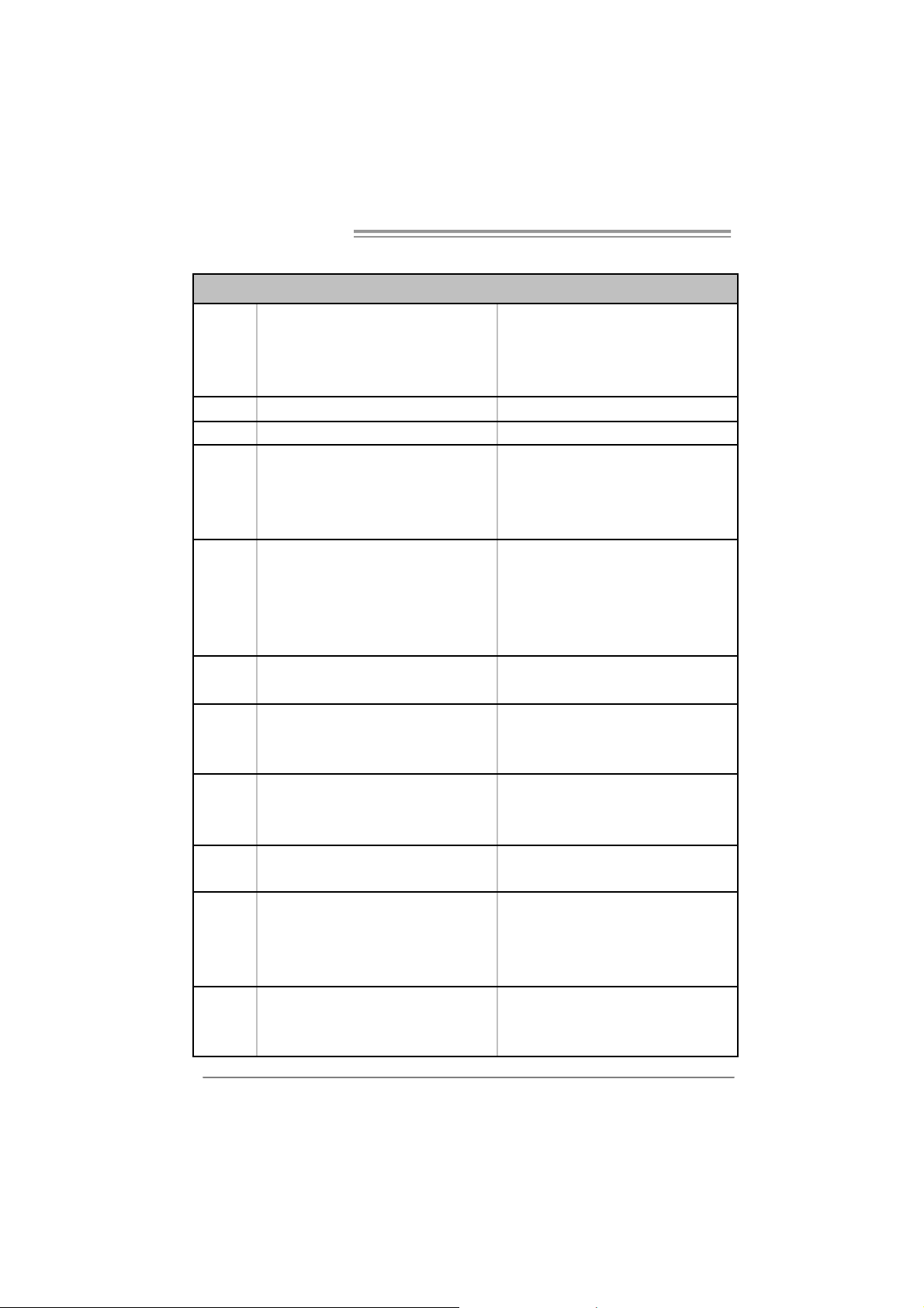
2.1 INSTALLING CENTRAL PROCESSING UNIT (CPU)
Step 1: Remove the socket protection cap.
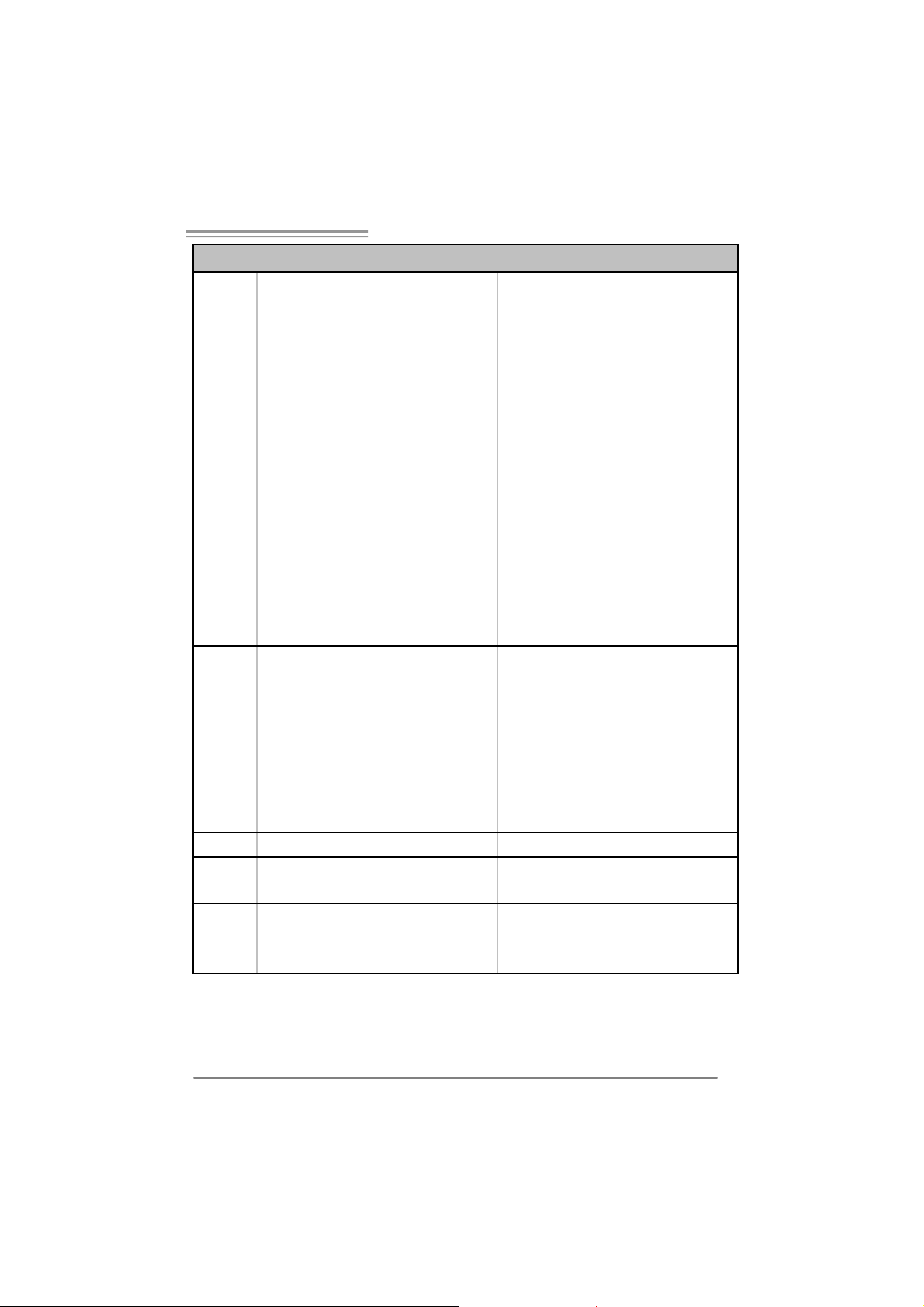
Step 2: Pull the lever toward directi on A from the socket and then raise the
lever up to a 90-degree angle.
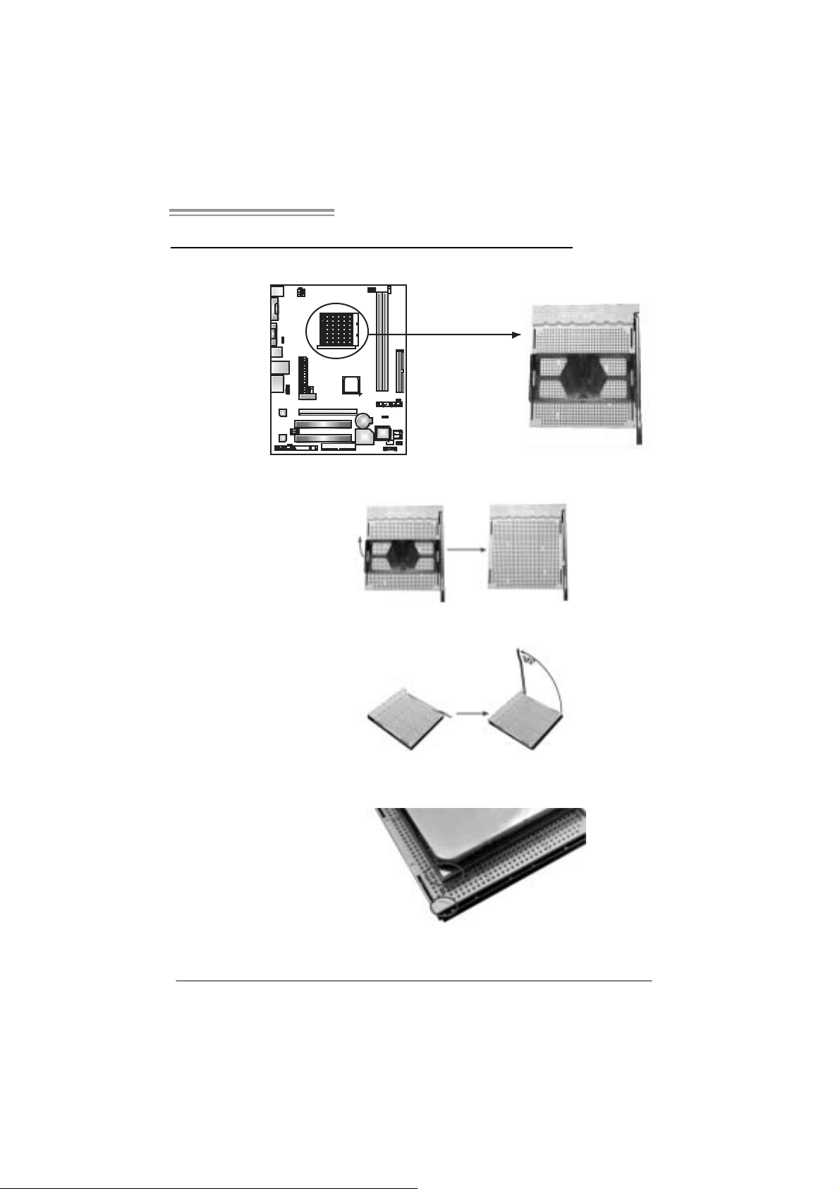
Step 3: Look for the white triangle on socket, and the gold triangle on
CPU should point towards thi s white triangl e. T he CPU will fit only
in th e cor r ec t or i en tation.
7
Motherboard Manual
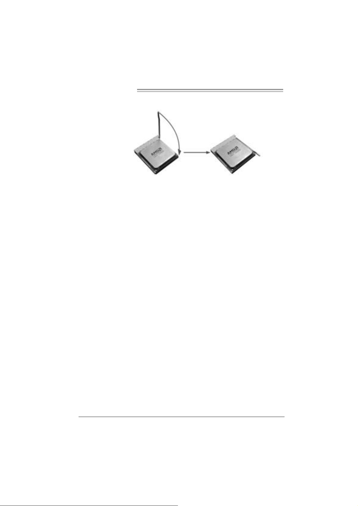
Step 4: Hold the CPU down firmly, and then close the lever toward direct
B to complete the install ation.
Step 5: Pu t the CPU F an on t he CPU a nd buckl e it . Co nn ec t the CPU
FAN power cable to the JCFAN1. This completes the installation.
8
NF61V Micro AM2 SE/NF61S Micro AM2 SE
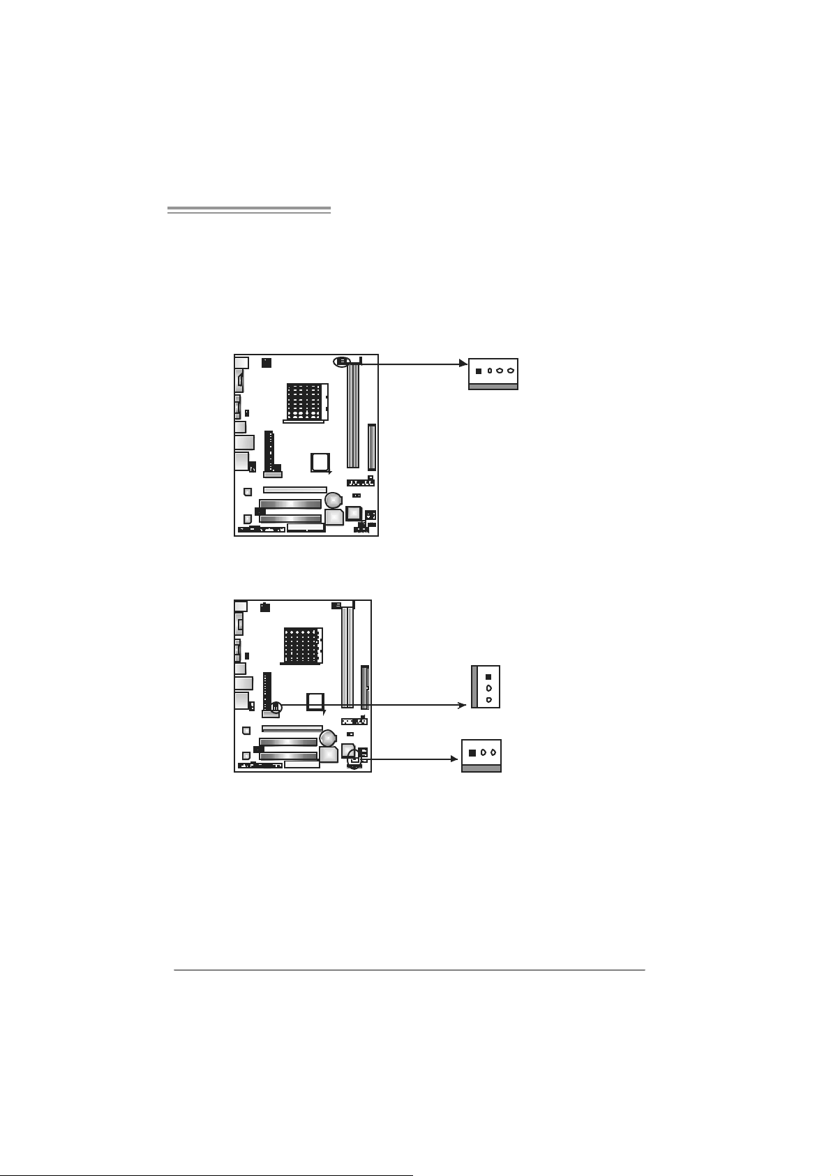
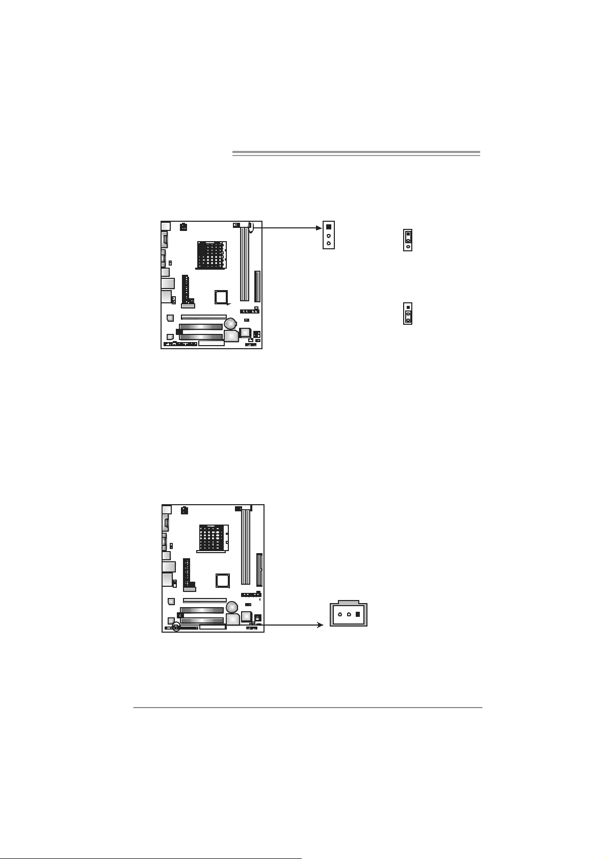
2.2 FAN HEADERS
These fan headers support cooling-fans built in the computer. The fan
cabl e and connector may be different according to the fan manufacturer.
Connect the fan cable to the connector while matching the black wire to
pin#1.
JCFAN1: CPU Fan Header
14
JCFAN1
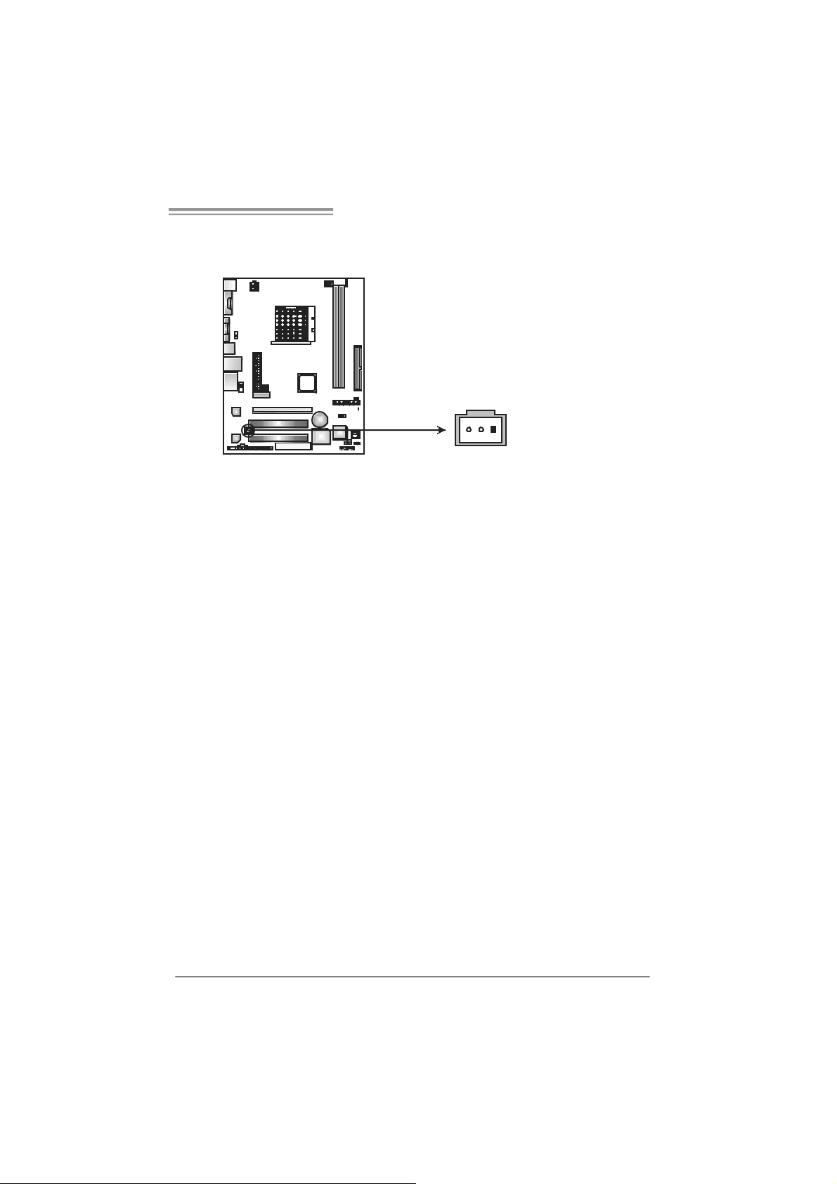
JSFAN1 : System Fan H ead er
JN FAN1 : North Bridge Fan Hea de r (Optional)
Pin
Assignment
1 Ground
2 +12V
3
FAN RPM rate
sense
4 Smart Fan
Control (By Fan)
JNFAN1
(Optional)
13
JSFAN1
Pin Assignment
1 Ground
1
3
2 +12V
3
FAN RPM rate
sense
Note:
The JCFAN1、JSFAN1 and JNFAN1 support 4-pi n and 3-pin head c onnector. When
connecting with wires ont o connectors, please note that the red wire is the positi ve and
shoul d be connected to pi n#2, and the bl ac k wire is Ground and s hould be c onnected to
GND.
9

Motherboard Manual
1
2.3 INSTALLING SYSTEM MEMORY
A. Me mor y Mo du le s
DIMMA1DIMMB
1. Unlock a DIMM sl ot by pressing the retaining clips outward. Align a
DIMM on the slot such that the notch on the DIMM matches the
break on the Slot.
2. Insert the DIMM vertically and fi rmly into the slot until the retaining
chip snap back in place and the DIMM is properly seated.
10
NF61V Micro AM2 SE/NF61S Micro AM2 SE
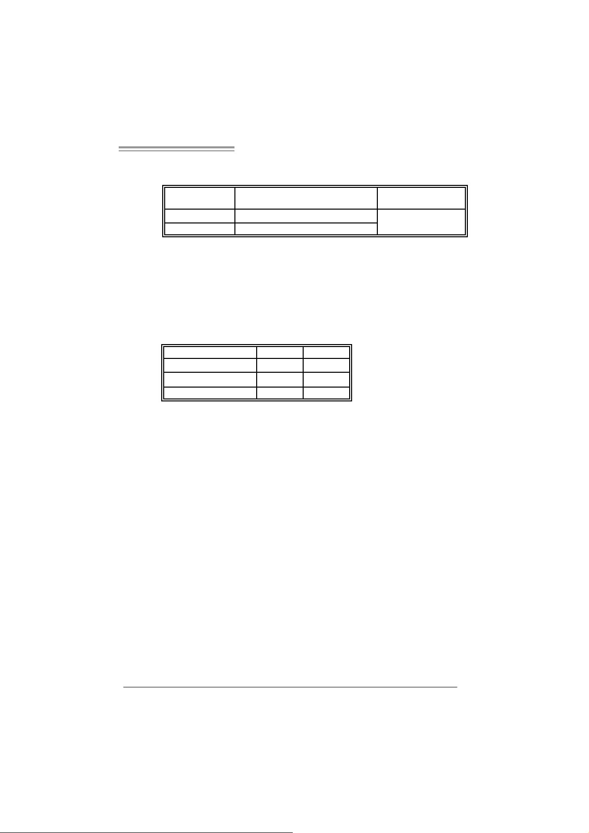
B. Memory Capacity
DI MM Socket
Location
DIMMA1 256MB/512MB/1024MB *1
DIMMB1 256MB/512MB/1024MB *1
C. Dual Channel Memory installation
To t rigger t he Dual Channel function of t he motherboard, the memory m odule
must mee t the following requirement s:
Install memory module of the s am e density in pair, shown in the following table.
Du al Channel Statu s
Disabled O X
Disabled X O
Enabled O O
(O means m emory installed, X means memory not installed.)
The DRAM bus width of the memory module must be the sam e (x8 or
x16)
DDR Module Total Memory Size
Max memory 2GB.
DIMMA 1
DIMMB1
11
Motherboard Manual
2.4 CONNECTORS AND SLOTS
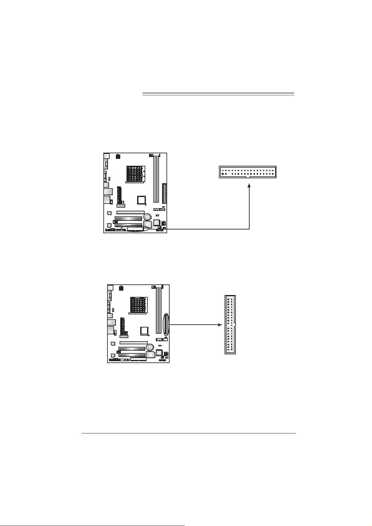
FDD1: Flo ppy Disk Connec tor
The motherboard prov ides a standard floppy disk connector that supports 360K,
720K, 1. 2M, 1.44M and 2. 88M floppy disk types. This connector supports the
provided f loppy drive ribbon cables.
2
133
34
IDE1: Hard Disk C onnector
The motherboard has a 32-bit Enhanced IDE Controller that prov ides PIO Mode
0~4, Bus Mast er, and Ult ra DMA 33/ 66/100/133 f unctionality.
The IDE connector can connect a mas t er and a slave drive, so you c an connect
up to two hard dis k drives.
40
39
12
1
2
NF61V Micro AM2 SE/NF61S Micro AM2 SE
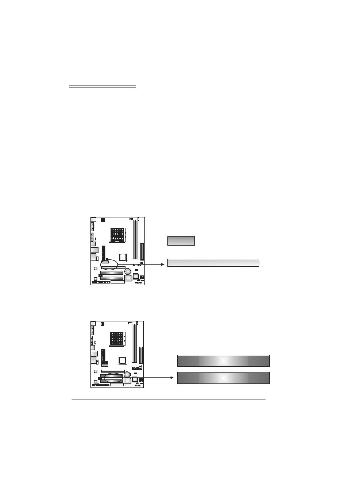
PE X1_1: P CI-Expres s x1 Slot
- PC I -Ex press 1.0a compliant.
- D at a transfer bandwidth up to 250MB/s per direction; 500MB/s in total.
- PC I -Ex press supports a raw bit-rate of 2.5Gb/s on the dat a pins.
- 2X bandwidth over the traditional PCI architecture.
PEX16_1: PCI-Express x16 Slot (x1 Spee d)
(for NF61V Micro AM2 SE)
- PC I -Ex press 1.0a compliant.
- Maxim um theoretical realized bandwidth of 250MB/s sim ultaneously per
direct ion, for an aggregat e of 500MB/s totally .
PEX16_1: PCI-Express x16 Slot (x8 Spee d)
(for NF61S Micro AM2 SE)
- PC I -Ex press 1.0a compliant.
- Maxim um theoretical realized bandwidth of 2GB/s simult aneously per
direct ion, for an aggregat e of 4GB/s totally.
PEX1_1
PEX16_1
PCI1~PCI2: Periphe ral Componen t In terconnect Slo ts
This mot herboard is equipped with 2 standard PCI slots. PCI stands for
Peripheral Com ponent Int erconnect, and it is a bus standard for expansion
cards . This PCI slot is des ignated as 32 bits.
PCI1
PCI2
13
Motherboard Manual
CHAPTER 3: HEADERS & JUMPERS SETUP
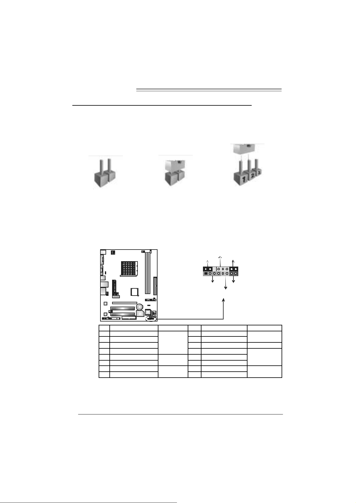
3.1 HOW TO SETUP JUMPERS
The illustration shows how to set up jumpers. When the jumper cap is
placed on pins, the jumper i s “close”, if not, that means the jumper is
“open”.
Pin opened Pin closed Pin1-2 closed
3.2 DETAIL SETT INGS
JPANEL1: Front Panel Header
This 16-pin connector includes Power-on, Reset, H DD LED, Power LED, Sleep
butt on and speaker connection. It allows us er to connect the PC case’s front
panel switch functions.
D
E
L
_
R
W
P
P
S
L
9
1
K
P
S
n
/
f
O
f
O
-
+
+
16
8
-
+
R
S
T
D
H
L
E
14
Pin Assignment Function Pin Assignment Functio n
1 +5V 9 Sleep control
2 N/A 10 Ground
3 N/A 11 N/A N/A
4 Speaker
5 HDD LED (+) 13 Power LED (+)
6 HDD LED (-)
7 Ground 15 Power button
8 Reset control
Speaker
Connector
Hard drive
LED
Reset button
12 Power LED (+)
14 Power LED (-)
16 Ground
Sleep button
Powe r LED
Power-on button
NF61V Micro AM2 SE/NF61S Micro AM2 SE
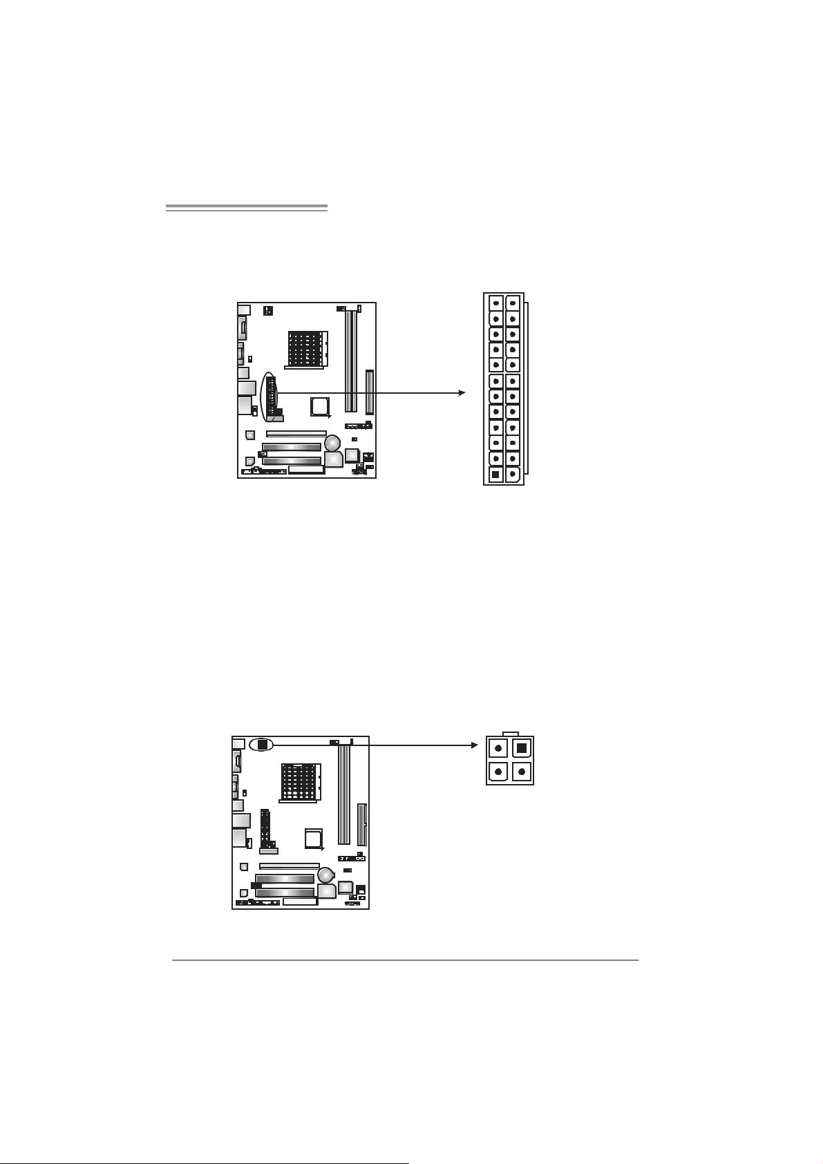
JATXPW R1: ATX Powe r So u rce Con ne ctor
This connector allows user to connect 24-pin power connector on the ATX
power supply.
12
1
Pin Assignment Pin Assignment
24
13
13 +3.3V 1 +3.3V
14 -12V 2 +3.3V
15 Ground 3 Ground
16 PS_ON 4 +5V
17 Ground 5 Ground
18 Ground 6 +5V
19 Ground 7 Ground
20 NC 8 PW_OK
21 +5V 9 Standby Voltage+5V
22 +5V 10 +12V
23 +5V 11 +12V
24 Ground 12 +3.3V
JATXPWR2: ATX Power Source Connector
By c onnecting this connector, it will prov ide +12V to CPU power c irc uit.
12
Pin
34
1 +12V
2 +12V
3 Ground
4
Assignment
Ground
15

Motherboard Manual
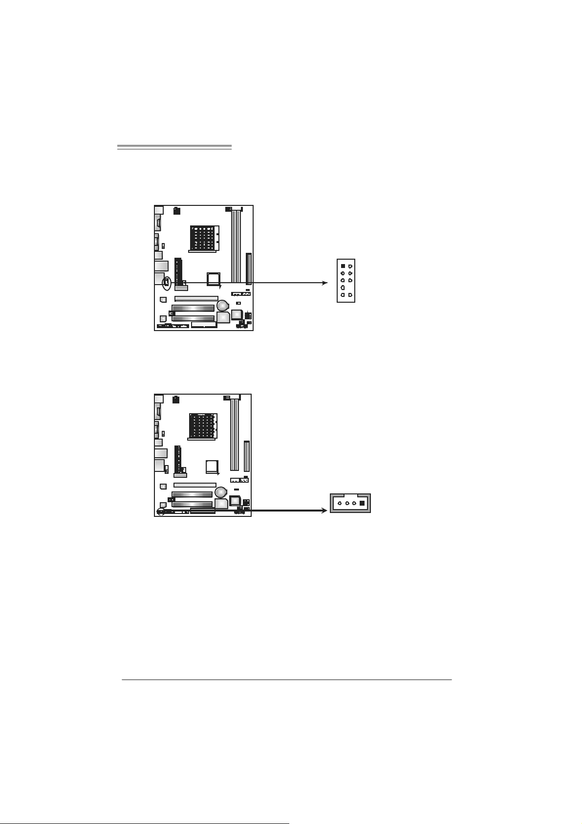
JUSB2/JUSB3: Headers for USB 2.0 Ports at Front Panel
This header allows user to connect addit ional USB cable on the PC front panel,
and also can be connected with internal USB devic es, like USB card reader.
JUSB 2
JUSB 3
210
1
JUSBV1/JUS B V2: Powe r Source H eaders for USB Ports
Pin 1-2 C lose:
JU SBV1: +5V for USB ports at JUSBLAN1.
JU SBV2: +5V for USB ports at front panel (JUSB2/JUSB3).
Pin 2-3 C lose:
JU SBV1: USB ports at JU SBLAN 1 are powered by +5V st andby volt age.
JU SBV2: USB ports at front panel (JU SB2/JUSB3) are powered by +5V
standb y vol tage.
Assignment
Pin
1 +5V (fused)
2 +5V (fused)
3 USB4 USB5 USB+
6 USB+
7 Ground
8 Ground
9 Key
9
10 NC
16
JUSBV1
3
1
13
JUSBV2
13
Pin 1-2 close
13
Pin 2-3 close
3
1
3
1
Note:
In order to support this function “Power-On system via USB devic e,” “JUSBV1/ JUSBV2”
jumper cap should be placed on Pin 2-3 indi vidually.
NF61V Micro AM2 SE/NF61S Micro AM2 SE
JAUDIOF1: Fron t Panel Audio Heade r
This header allows user to connec t t he front audio out put cable with the PC f ront
panel. It will disable the output on back panel audio c onnectors.
Pin Assignment
1 Mic in
2 Ground
3 Mic power
4 Audio power
5 Right line
1
9
2
10
JCDIN1: CD-R OM A ud io- in Connector
This connector allows user to c onnect the audio s ourc e f rom the variaty devices,
like CD-R OM, DVD-ROM, PCI sound c ard, PCI TV turner card etc.
14
out
6 Ground
7 Reserved
8 Key
9 Left line out
10 Ground
Assignment
Pin
1 Left Channel
Input
2 Ground
3 Ground
4 Right Channel
Input
17

Motherboard Manual
JCMOS 1 : C lear CMOS Hea der
By plac ing the jumper on pin2-3, it allows user to restore the BIOS safe sett ing
and the CMOS dat a, please carefully follow the proc edures to avoid damaging
the m otherboard.
※ Clear CMOS Procedures:
1. Rem ov e AC power line.
2. Set the jumper to “Pin 2-3 close”.
3. Wai t for fi ve se co n ds.
4. Set the jumper to “Pin 1-2 close”.
5. Power on the AC.
6. Res et your desired pass word or clear the CMOS dat a.
13
Pin 1-2 Close:
Norm al O peration
(default).
3
1
Pin 2-3 Close:
Clear CMO S
data.
13
JCI1: Chassis O pen Header (Optional)
This connector allows system to monitor PC cas e open stat us. If the signal has
been triggered, it will record to the CMOS and show the message on next
boot-up.
18
Pin
Assignment
1 Case open
signa l
1
2
2 Ground
NF61V Micro AM2 SE/NF61S Micro AM2 SE
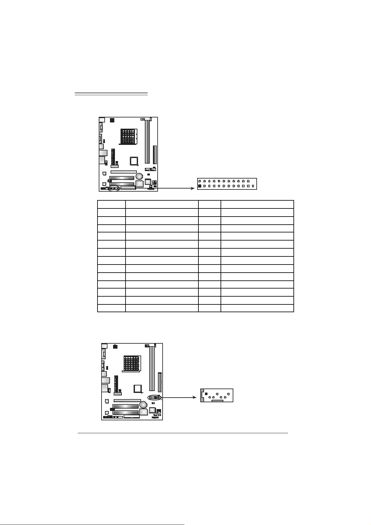
JPRNT1: Printer Port Con nector
This header allows you to connector printer on the PC.
2
1
25
Pin Assignment Pin Assignment
1 -Strobe 14 Ground
2 -ALF 15 Data 6
3 Data 0 16 Ground
4 -Error 17 Data 7
5 Data 1 18 Ground
6 -Init 19 -ACK
7 Data 2 20 Ground
8 -Scltin 21 Busy
9 Data 3 22 Ground
10 Ground 23 PE
11 Data 4 24 Ground
12 Ground 25 SCLT
13 Data 5 26 Key
S ATA1~ SATA2: Serial ATA Connectors
The motherboard has a PCI to SATA Controller with 2 channels SATA interface,
it satisfies the SATA 2.0 spec and with transfer rate of 3.0Gb/s.
Pin
Assignment
1 Ground
2 TX+
3 TX-
147
4 Ground
5 RX6 RX+
7 Ground
SATA2 SATA1
19
Motherboard Manual
Header f or Mem ory over -voltage: JD DR I I _22V 1
When proc essing Memory over-voltage, please place the jumper to pin2-3
Clos ed. The D ef ault setting is Pin 1-2 Clos ed.
1
3
Norm al s tat us ( defa ult).
Mem or y v oltage 2.2V.
1
3
Pin 1- 2 Cl os e:
1
3
Pin 2- 3 Cl os e:
Note:
1. When “JDDRII_22V1” jumper cap is placed on Pin 1-2, mem ory voltage
can be manually adjusted in CMOS s et up screen.
2. When “JDDRII_22V1” jumper cap is placed on Pin 2-3, mem ory voltage
will be f ix ed at 2.2V automat ically, and can’t be adjusted under C OMS
setup.
Before setting memory o ver- vol tage, please ensure tha t your DDR2 suppor ts up
to 2.2V. ( Consult your DDR2 supplier)
JSPDIF_O UT1 : Digital Audio-out Con n ector
This connector allows user to connect the PCI brack et SPDIF output header.
Pin
Assignment
1 +5V
2 SPDIF_OUT
3 Ground
20
13
NF61V Micro AM2 SE/NF61S Micro AM2 SE
JSPDIF_IN1: Digital Audio-in Connector (optional )
This connector allows user to connect the PCI brack et SPDIF input header.
Pin
Assignment
1 +5V
2 SPDIF_IN
3 Ground
13
21
Motherboard Manual
CHAPTER 4: RAID F UNCTIONS
4.1 OPERATION SYSTEM
Supports Windows XP H om e/Professional Edition, and Windows 2000 Professional.
4.2 RAID ARRAYS
RAI D supports the following ty pes of R AID array s :
RAID 0: RAID 0 defines a disk striping scheme that improves disk read and write times for
many applications.
RAID 1: RAID 1 defines techniques for mirroring data.
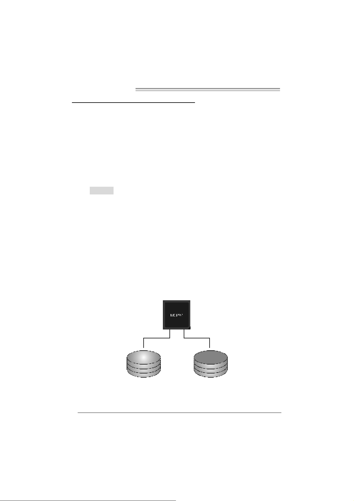
4.3 HOW RAID WORKS
RAID 0:
The controller “strip es” d ata across multipl e drives in a RAID 0 array system. It breaks
up a large file into smaller blocks and performs disk reads and writes across multiple
drives in parallel. The size of each block is determined by the stripe size parameter,
which you set during the creation of the RAID set based on the system environment. This
technique reduces overall disk access t ime and offers high bandwidth .
Fea tures and Be nefits
Drives: Minimum 1, and m ax imum is up to 6 or 8. Depending on the
platform.
Uses: I ntended for non-critical data requiring high data throughput, or any
environment that does not require fault toleranc e.
Benefits: prov ides increas ed dat a throughput, espec ially for large f iles. No
capac ity loss penalty for parity.
Drawbacks: Does not deliver any fault tolerance. If any drive in the array
fails, all dat a is lost.
Fault To le rance : No.
22
Blo c k 1
Bl o ck 3
Bl o ck 5
Bl o ck 2
B lock 4
B lock 6
NF61V Micro AM2 SE/NF61S Micro AM2 SE
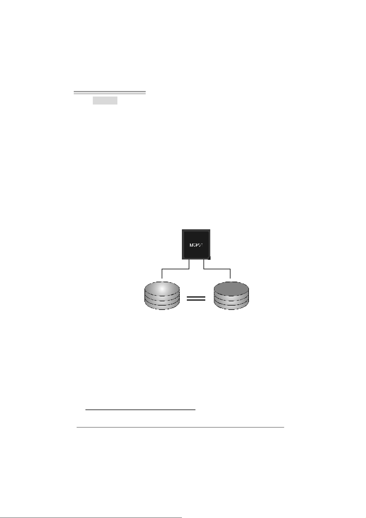
RAID 1:
Every read and write is actually carried out in parallel across 2 disk drives in a RAID 1
array system. The mirrored (backup) copy of the data can reside on the same disk or on
a second redundant drive in the array. RAID 1 provides a hot-standby copy of data if
the active v olume or drive is corrupted or becomes un available b ecause of a hardware
failure.
RAID techniques can be applied for high-availability solutions, or as a form of
automatic backup that eliminates tedious manual backups to more expensive and less
reliable media.
Fea tures and Be nefits
Drives: Minimum 2, and max imum is 2.
Uses: RAID 1 is ideal f or small dat abas es or any ot her applicat ion t hat
requires f ault tolerance and minimal ca paci t y.
Benefits: Provides 100% data redundancy. Should one driv e f ail, the
controller switche s to the other dri ve.
Drawbacks: Requires 2 drives for the storage space of one driv e.
Performanc e is impaired during drive rebuilds.
Fa ult To le ranc e : Yes.
Blo c k 1
Bl o ck 2
Bl o ck 3
Block 1
Bl o ck 2
Bl o ck 3
※ For more detailed setup information, please refer to the Driver CD, or go to
http://www.nvidia.com/page/pg_20011106217193.html to download NVIDIA nForce Tutorial Flash.
23

Motherboard Manual
CHAPTER 5: USEFUL HE LP
5.1 DRIVER INSTALLA TION NOTE
After you installed your operating system, please insert the Fully Setup
Dri ver CD into your optical drive and install the driver for better system
performance.
You will see the following window after you insert the CD
The setup gu ide will auto detect yo ur mothe rboard and opera ting system.
Note:
If this window didn’t show up after you ins ert the Driver CD, please use file brows er to
l ocate an d e xecu t e th e fil e SETU P.EXE under your opt ic al dr i ve.
A. Driver Install ation
To install the driver, please click on the Driver icon. The setup guide will
list the compatible driver for your m otherboard and operating system.
Click on each device driver to launch the installation program.
B. Software Installation
To install the software, please click on the Software icon. T he setup guide
will list the software available for your system, click on each software title
to la unch the insta l lat io n pr ogr a m.
C. Manual
Asi de from the paperback manual, we also provide manual in the Driver
CD. Click on the Manual icon to browse for available manual.
Note:
You will need Acrobat Reader to open the man ual file. Ple ase downloa d the la tes t ve rs ion
of Acrobat Reader software from
http://www.adobe.com/products/acrobat/readstep2.html
24
NF61V Micro AM2 SE/NF61S Micro AM2 SE
5.2 AWARD BIOS BEEP CODE
Beep Sound Meanin g
One long beep followed by t wo short
beeps
High-low siren sound CPU overheated
One Short beep when system boot-up No error found during POST
Long beeps every ot her second No DRAM detec t ed or inst all
Video card not found or video card
mem ory bad
Sys t em will s hut down automat ically
5.3 EXT RA INFORMATION
A. BIOS Update
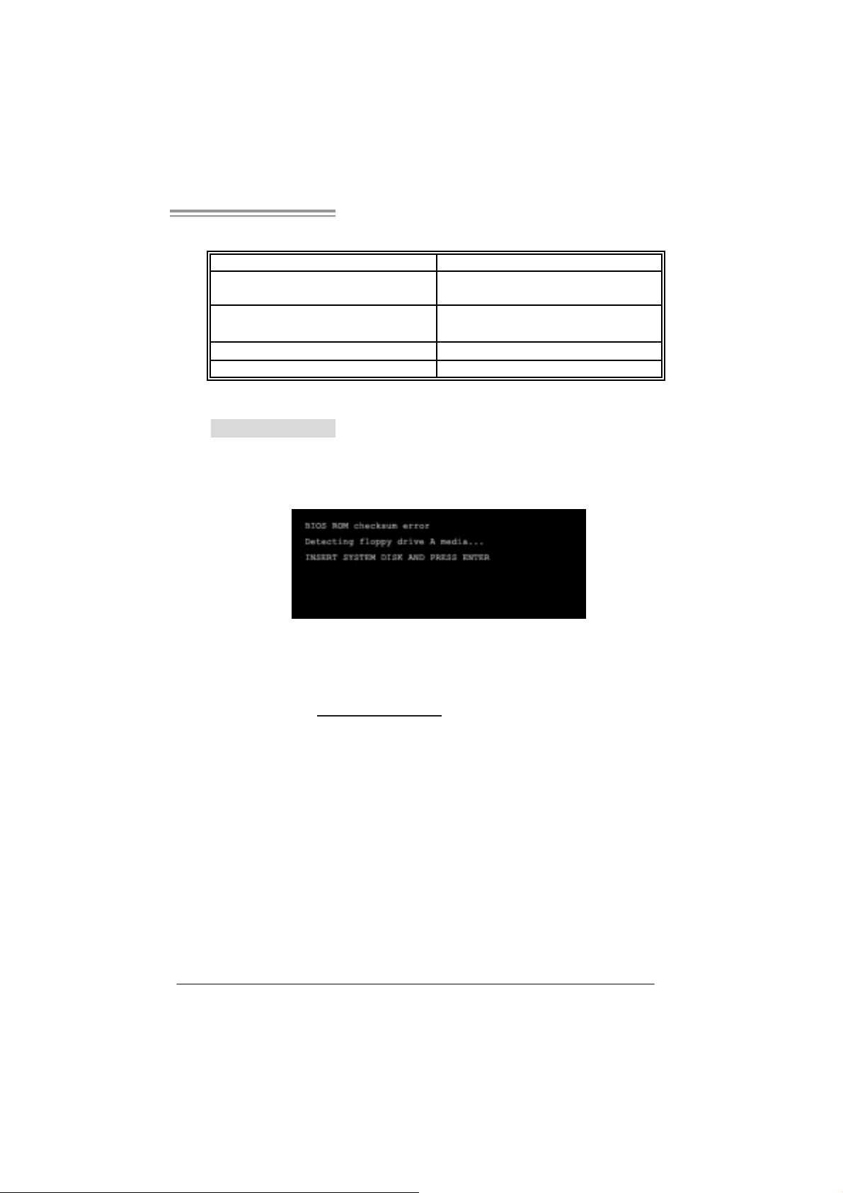
After yo u fail to update BIOS or BIOS is invaded by virus, the
Boot-Block function will help to restore BIOS. If the following message
is shown after boot-up the system, i t means the BIOS contents are
corrupted.
In thi s Case, please follow the procedure below to restore the BIOS:
1. Mak e a bootab le floppy d is k.
2. Download the Flash Utility “AWDFLASH.exe” from the Biostar
website: www.bi o star.com.tw
3. Confirm motherboard model and download the respecti vely BIOS
fr om Bi os t ar websit e.
4. Copy “AWDFLASH.exe” and respectively BIOS into fl oppy disk.
5. Insert the bootable disk into floppy drive and press Enter.
6. Syste m will boo t-u p t o DOS prompt .
7. Type “Awdflash xxxx.bf / sn/py/ r” in DOS prompt.
(xxxx means BIOS name.)
8. Syste m will upd ate BIOS au to matic ally an d re sta rt.
9. The BIO S h as been recovered a nd will work p roperly.
25

Motherboard Manual
B. CPU Overheated
If the system shutdown automati cally after power on system for
seconds, that means the CPU protection function has been activated.
When the CPU is over heated, the motherboard will shutdown
automati cally to avoid a damage of the CPU, and the system may not
power on again.
In thi s case, please double check:
1. The CPU cooler surface is placed evenly with the CPU surface.
2. CPU fan is rotated no rmally.
3. CPU fan speed is fulfilling with the CPU speed.
After confirmed, please follow steps below to relief the CPU protection
function.
1. Remove the power cord from power supply for seconds.
2. Wait for seconds.
3. Plug in the power cord and boot up the system.
Or you can:
1. Clear the CMOS data.
(See “Close CMOS Header: JCMOS1” section)
2. Wait for seconds.
3. Pow er on the sy st em again.
26
 Loading...