

Page 1

NF61V Micro AM2 / NF61S Micro AM2
Setup Manual
FCC Inf or m at ion and Copyr ight
This equipment has been tested and found to comply with the limits of a Class
B digital devic e, pursuant to Part 15 of the FCC Rules. These limits are designed
to provid e reasonab le p rotec tion ag ai nst har mful inter fe rence in a resi de ntial
installation. T his equipment generates, uses and can radiate radio frequency
energy and, if not ins talled and used in accordance with the instructions, may
cause harmful interference to radio communications. There is no guarantee
that interfe rence will not occur in a pa r ticular ins ta lla tion.
The vendor makes no re p res e ntatio ns or wa rranties wi th respec t to th e
contents here and specially disclaims any implied warranties of merchantability
o r f i tn es s fo r any p u rp ose . F u rt he r t he ve nd o r res e rves t he ri g ht to r ev is e t h is
publication and to make changes to the contents here without obligation to
notify any party beforehand.
D up lic a ti on o f this pu bl icat io n , i n pa rt o r in whole, is not al lo wed without first
obtaining the vendor’s approval in writing.
The content of this user’s manual is subject to be changed without notice and
we will not be res ponsible fo r any mis takes found in this use r’s manual. All the
brand and produc t names are trademarks of their respective companies.
Page 2

Table of Contents
Chapter 1: Introduction .............................................1
1.1 Before You Start................................................................... 1
1.2 Package Checklist................................................................1
1.3 Motherboard Features..........................................................2
1.4 Rear Panel Connectors..........................................................3
1.5 Mo t he r bo ar d Layou t............................................................4
Chapter 2: Hardware Installation ..............................5
2.1 Installing Central Pro ce ssing Unit (CPU)................................ 5
2.2 FAN Headers........................................................................7
2.3 Installing Sy stem Me mory......................................................8
2.4 Con necto rs a nd Slo ts............................................................10
Chapter 3: Headers & Jumpers Setup......................12
3.1 How to Setu p Ju mper s..........................................................12
3.2 Det ail Settin gs.....................................................................12
Chapter 4: RAID Functions.......................................19
4.1 Operation Syste m................................................................19
4.2 Raid Arrays.........................................................................19
4.3 How RA I D Wor k s.................................................................19
Chapter 5: Useful Help ..............................................21
5.1 Driver Instal lation Note .......................................................21
5.2 Award BIOS Bee p Code........................................................22
5.3 Extra Informati on ................................................................22
5.4 Troubleshooting...................................................................24
Chapter 6: WarpSpeeder™ .......................................25
6.1 Introduction........................................................................25
6.2 System Requirement............................................................25
6.3 Installation.........................................................................26
6.4 WarpSpeeder™ ....................................................................27
Appendencies: SPEC In Other Language ................34
Germa n................................................................................................34
France..................................................................................................36
Italian..................................................................................................38
Spanish................................................................................................40
Portuguese...........................................................................................42
Polish...................................................................................................44
Russian ................................................................................................46
Arabic..................................................................................................48
Japanese ..............................................................................................50
Page 3

NF61V Micro AM2 / NF61S Micro AM2
CHAPTER 1: INTRODUCTION
1.1 BEFORE YOU START
Tha nk you for choo sing our product. Before you s tart ins talling the
mo the rboa rd, plea se make sure you follo w the ins tructio ns be lo w:
Prepare a dry and stable working environment with
s uf ficie nt lighting .
Always disconnect the computer from power outlet
be fo re ope ra tion .
Befo re you ta ke the mo the rboa rd ou t f rom a n ti -s ta tic
bag, ground yourself properly by touching any safely
grounde d appliance, o r use g rounded wrist s trap to
remove the static charge.
Avo id to u c h ing the com pone nts o n mo the rboa rd o r the
rea r side of the boa rd unless ne cessary. Hold the boa rd
on the edge , do no t try to be nd o r flex the board.
Do no t leave an y unfas tene d sma ll parts inside the
case after installation. Loose parts will cause short
circu its which ma y damage the equ ipment.
Keep the computer from dangerous area, such as heat
so u rce, humid a ir and water.
1.2 PACKAGE CHECKLIST
FDD Cable X 1
HDD Cable X 1
Use r’s Ma nua l X 1
Fully Setup Drive r CD X 1
Rear I/O Panel for ATX Case X 1
Se ria l ATA C a b le X 1 ( op ti ona l)
USB 2.0 Cable X1 (optional)
S/PDIF Cable X 1 (optional)
Se ria l ATA Po we r Switch Cab le X 1 (op tiona l)
Printer Port Cable X 1 (op tional)
1
Page 4
Motherboard Manual
y
r
1.3 MOTHERBOARD FEATURES
NF61V MICRO A M2 NF61S MICRO AM2
Socket AM2
CPU
FSB Supports up to 1GHz Bandwidth Supports up to 1GHz Bandwidth
Chipset
Super I/O
Main
Memory
Graphics
IDE
SA TA II
LAN
Sound
Slots
On Board
Connector
AMD Sempron / Athlon 64 / Athlon 64 FX /
Althlon 64 X2 processors
Supports Hyper Transport and Cool=n=Quiet
MC P61V ( GeFor ce 61 00- 400) MC P61S ( GeFor ce 61 00- 405)
ITE 8716F
Provides the most commonl
I/O functionality.
Low Pin Count I nterface
DIMM Slots x 2
Eac h DIMM supports 256/512MB & 1GB DDR 2
Max Memory Capicity 2GB
Dual Channel Mode DDR2 memory module
Supports DDR2 400 / 533 / 667 / 800
Integrated in MCP61V Chipset
Max Shared Vi deo M emory is 256MB
Integrated IDE Controller
Ultra DMA 33 / 66 / 100 / 133 B us Mast er Mode
supports PIO Mode 0~4
Integrated Serial ATA Controller
Data transfer rates up to 3.0 Gb/s.
SATA Version 2.0 specification compliant.
Realt ek 8201CL PHY
10 / 100 Mb/s Auto-Negotiation
ALC861
8 channels audio out
Intel High-Definition Audio support
PCI s lot x2 PCI s lot x2
PCI Express x16 slot (x1 Speed) x1 PCI Express x 16 sl ot (x8 S peed) x1
PCI Express x 1 slot x1 PCI Express x 1 slot x1
Fl oppy c onnector x1 Fl oppy c onnector x1
IDE C onnector x1 IDE Connector x1
SA TA2 C on nect or x2 SA TA2 C on nect or x2
Front Panel Connector x1 Fr ont Panel Connector x1
Front A udio Connector x1 Front A udio Connector x1
CD- in C onnec tor x1 C D-i n Connector x1
S/PDIF out c onnector x1 S/PDIF out connector x1
CP U Fa n header x1 C PU F an header x1
Sys tem F an header x2 S ystem Fan hea der x2
us e d legacy Supe
2
Socket AM2
AMD Sempron / Athlon 64 / Athlon 64 FX /
Althlon 64 X2 processors
Supports Hyper Transport and Cool=n=Quiet
ITE 8716F
Provides the most commonly used legacy Super
I/O functionality.
Low Pin Count I nterface
DIMM Slots x 2
Eac h DIMM supports 256/512MB & 1GB DDR 2
Max Memory Capicity 2GB
Dual Channel Mode DDR2 memory module
Supports DDR2 400 / 533 / 667 / 800
Integrated in MCP61S Chipset
Max Shared Vi deo M emory is 256MB
Integrated IDE Controller
Ultra DMA 33 / 66 / 100 / 133 B us Mast er Mode
supports PIO Mode 0~4
Integrated Serial ATA Controller
Data transfer rates up to 3.0 Gb/s.
SATA Version 2.0 specification compliant.
Realt ek 8201CL PHY
10 / 100 Mb/s Auto-Negotiation
ALC861
8 channels audio out
Intel High-Definition Audio support
Page 5
NF61V Micro AM2 / NF61S Micro AM2
NF61V MICRO A M2 NF61S MICRO AM2
CMOS clear header x1 CMOS clear header x1
USB connector x2 USB connector x2
Printer Port Connector x1 Printer Port Connector x1
Cha ssis o pen hea der(Opti onal) x1 C hassis open he ader(O pti onal) x1
Power Connector (24pin) x1 Power Connector (24pin) x1
Power Connector (4pin) x1 Power Connector (4pin) x1
PS/2 Keyboard x1
PS/2 Mouse x1
Back Panel
I/O
Bo ard S ize 205 x 244 (m m) Micro A TX Size Bo ard 205 x 244 (m m ) M ic ro A TX Siz e B oard
Special
Features
OS S upport
S e ri a l P ort x 1
VGA port x1
LAN port x1
USB Port x4
Audio Jack x6
NVIDIA nTunes
RAID 0 / 1 s upport
Wi ndows 2000 / XP
Biostar Reserves the right to add or remove
support for any OS With or without notice.
PS/2 Keyboard x1
PS/2 Mouse x1
S e ri a l P ort x 1
VGA port x1
LAN port x1
USB Port x4
Audio Jack x6
NVIDIA nTunes
RAID 0 / 1 s upport
Wi ndows 2000 / XP
Biostar Reserves the right to add or remove
support for any OS With or without notice.
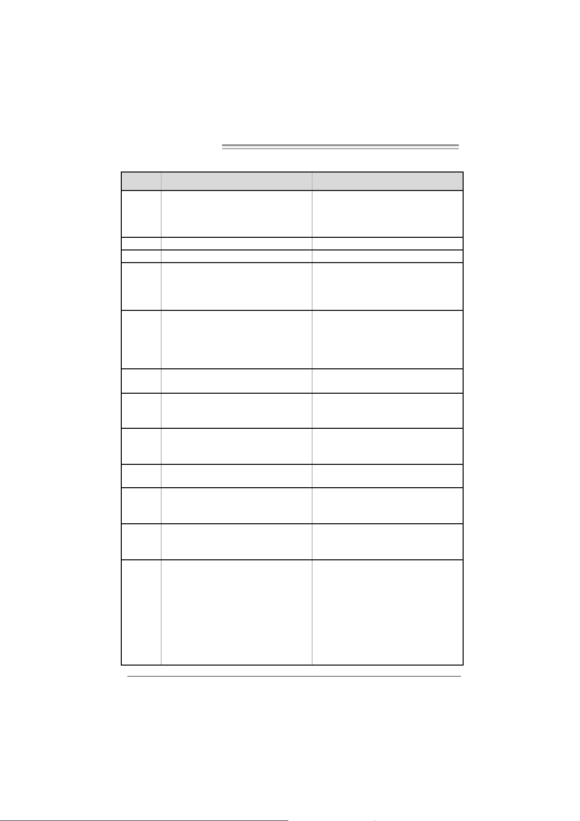
1.4 REAR PANEL CONNECTORS
PS/2
Mouse
PS/ 2
Ke yboard
COM1 VGA
Center
Rear
Sid e
Line In
Line Out
Mic I n
LAN
USBX2USBX2
3
Page 6
Motherboard Manual
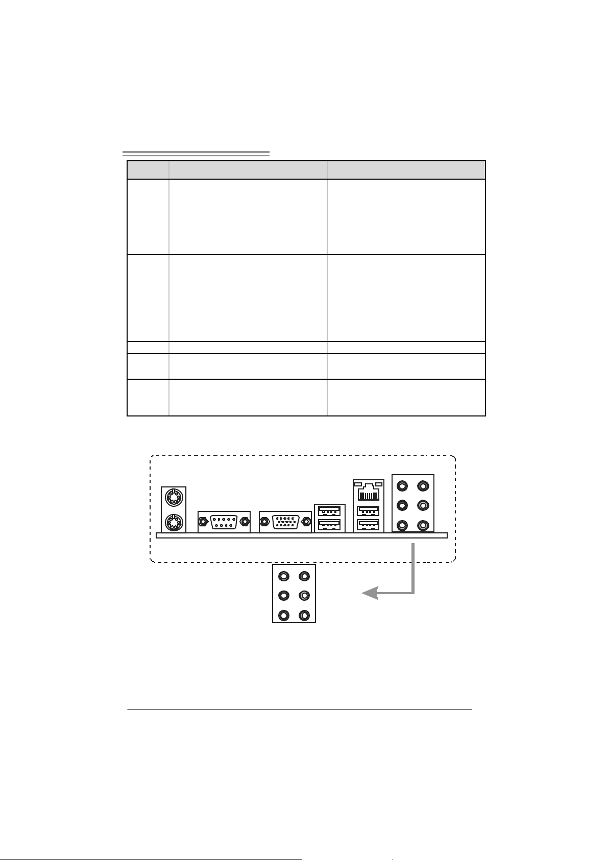
1.5 MOTHERBOARD LAYOUT
JKBMS1
JCOM1
JVG A1
JUSB1
JUSBLAN1
AUDIO 1
JUSBV1
JAUDIOF1
JA TXPWR2
PCI-EX1_1
JA TXPWR1
JNFAN1
MCP61V
or
MCP61S
Socket A M2
JCFAN1
JDDR II_22V1
DIMM A1
DIMM B1
IDE1
JCI1(Opt ional)
LAN
Codec
JCDIN1 J SPDIF_OU T1 J PRNT1
Note: represents the 1■
4
PCI-EX16
PCI1
PCI2
FDD1
st
pin.
BAT1
Super I/O
JSAT A2 JSATA1
JCMOS1
JUSB2
BI OS
JUSB3
JSFAN1
JUSBV2
JPANEL1
Page 7
NF61V Micro AM2 / NF61S Micro AM2
CHAPTER 2: HARDWARE INSTALLATION
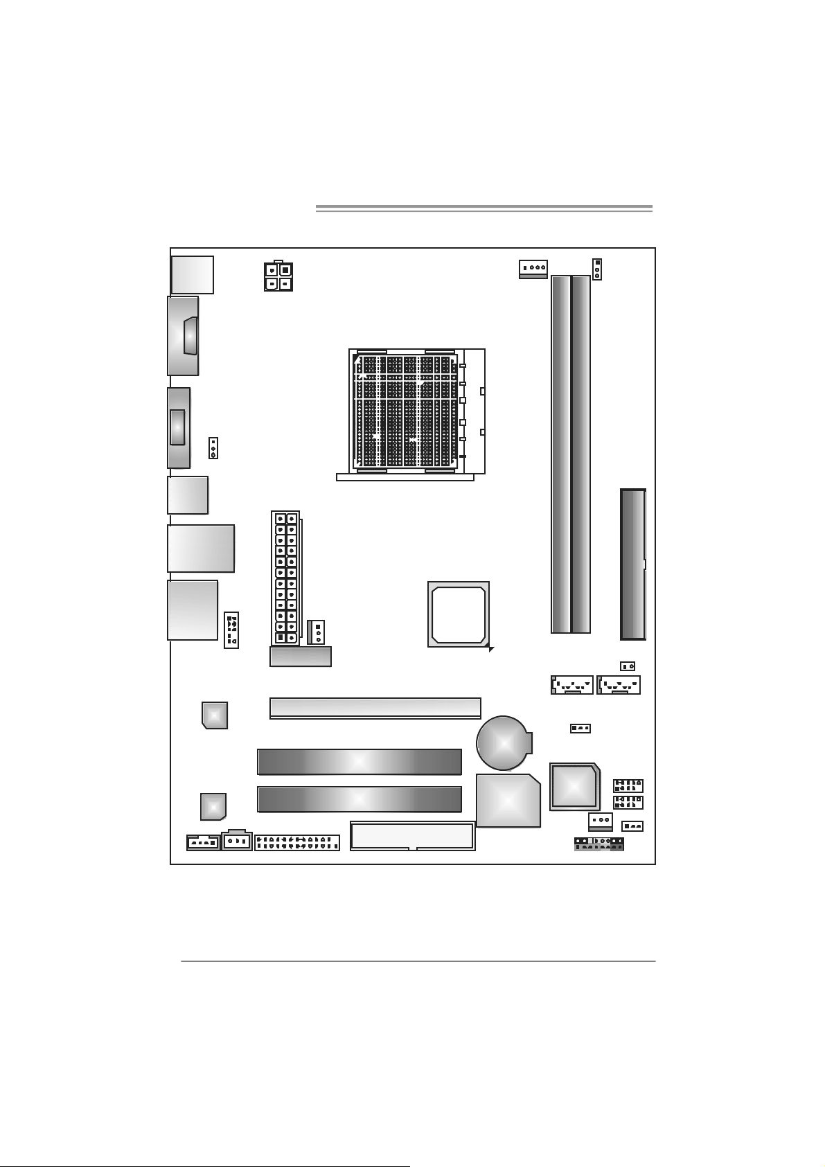
2.1 INSTALLING CENTRAL PROCESSING UNIT (CPU)
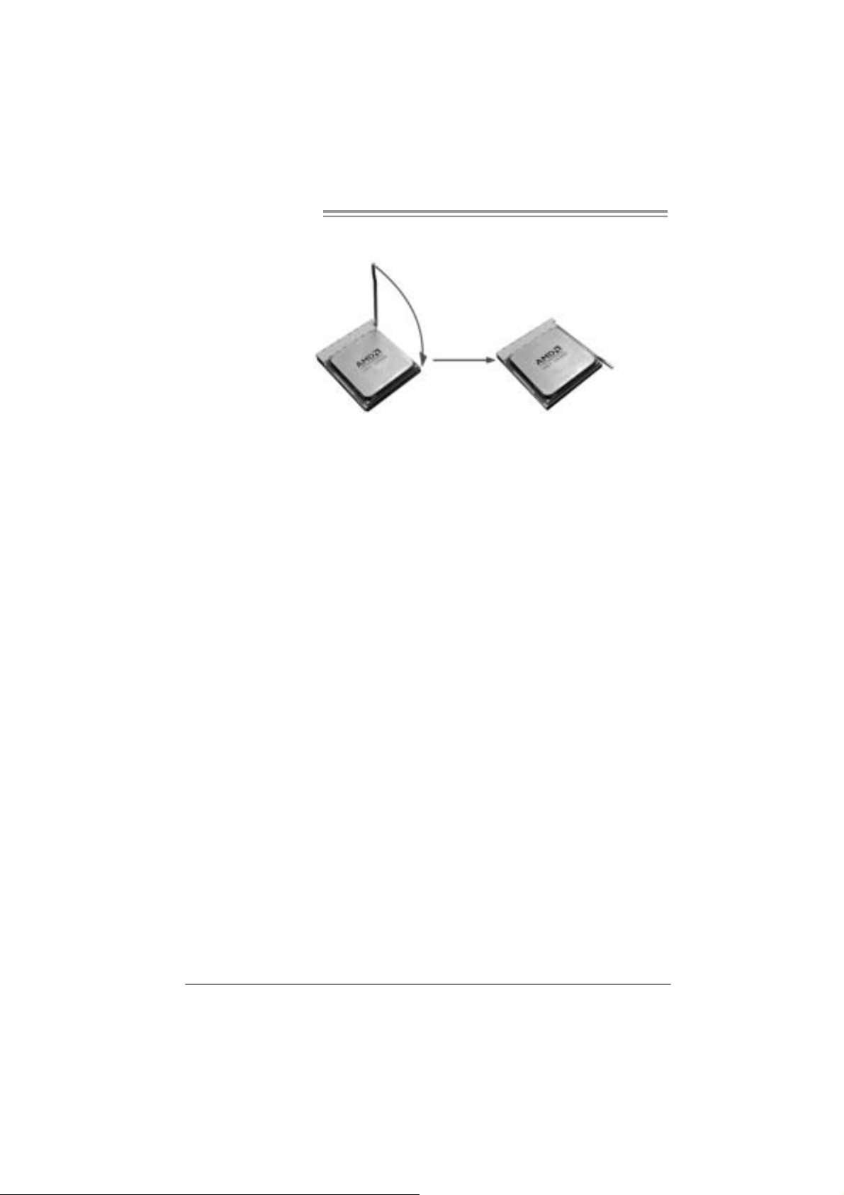
Step 1: Remove the socket protecti on cap.
Step 2: Pull the l ever toward direction A from the socket and then raise the
lever up to a 90-degree angl e.
Step 3: Look for the white triangle on socket, and the gol d triangle on
CPU should point towards this white triangle. The CPU will fit only
in th e cor r ec t or i en tation.
5
Page 8
Motherboard Manual
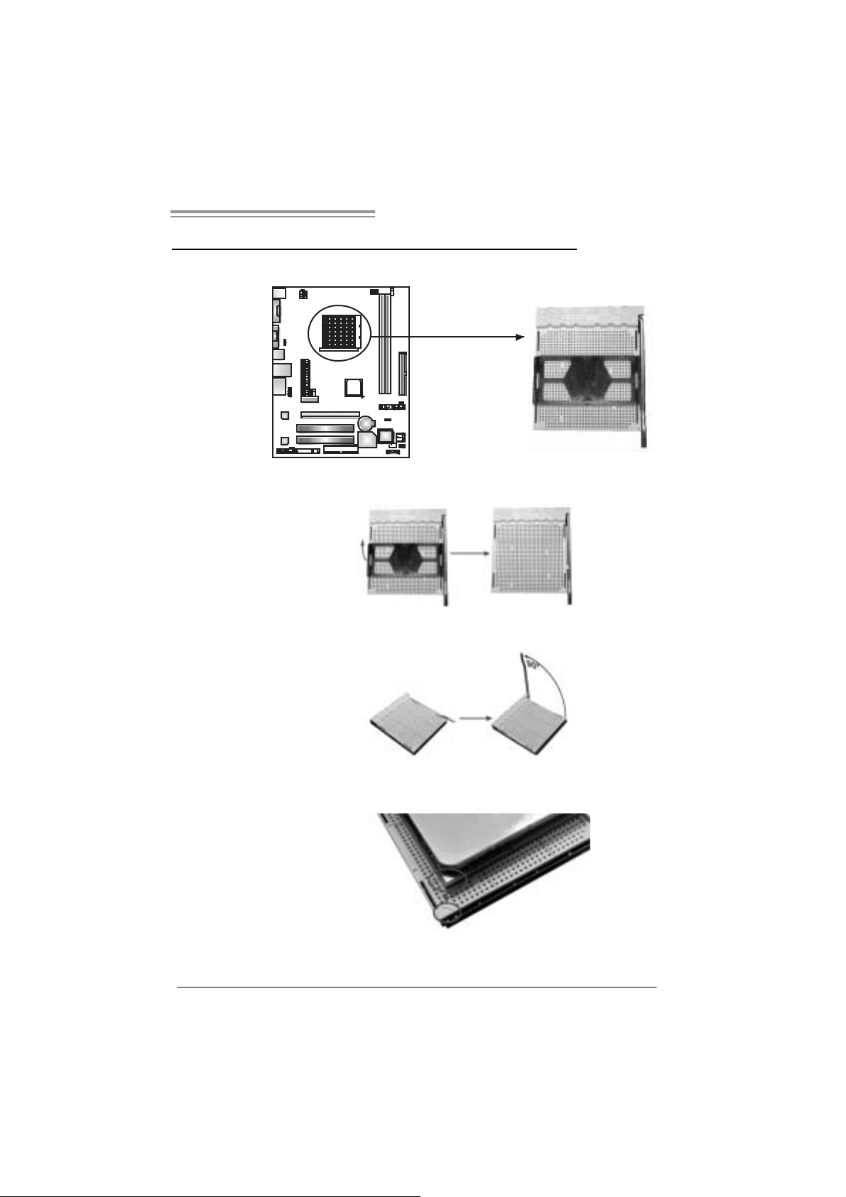
Step 4: Hold the CPU down firmly, and then cl ose the lever toward direct
B to complete th e installation.
Step 5: Pu t the CPU Fan on t he CPU a nd buckl e it . Conne c t the CPU
FAN power cable to the JCFAN1. This completes the installation.
6
Page 9
NF61V Micro AM2 / NF61S Micro AM2
1
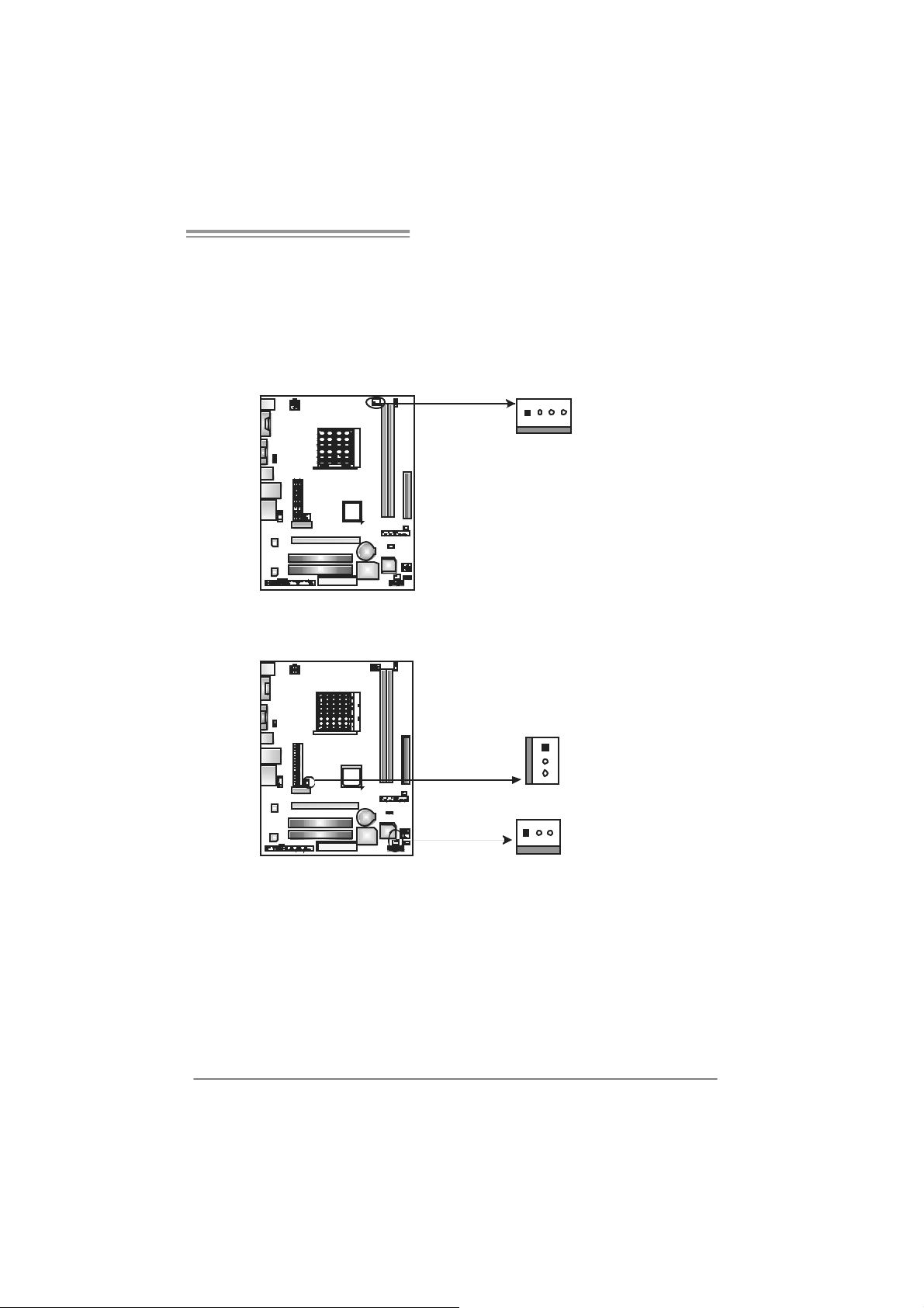
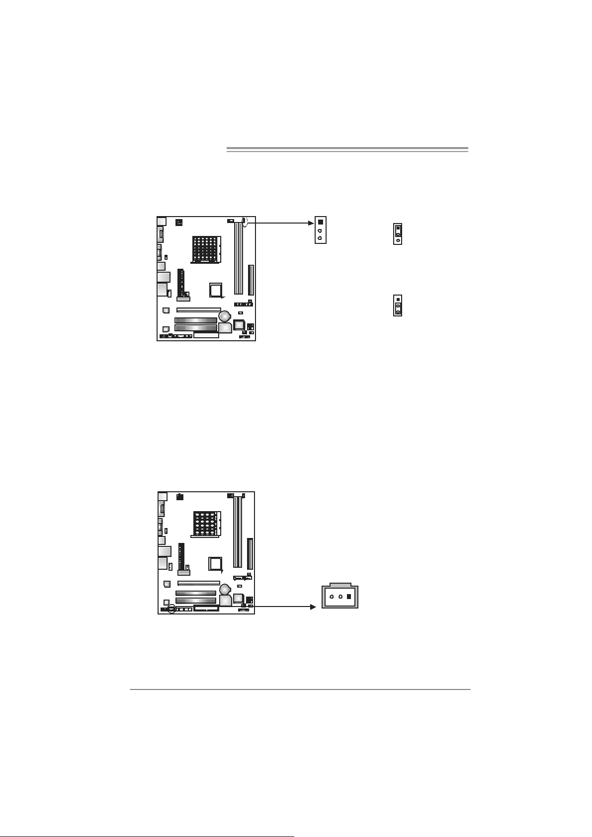
2.2 FAN HEADERS
These fan headers support cooling-fans built in the computer. The fan
cabl e and connector may be different accordi ng to the fan m anufacturer.
Connect the fan cable to the connector while m atching the black wire to
pin#1.
JCFAN1: CPU Fan Header
14
JCFAN1
JSFAN 1: System Fan Head er
JNFAN1: North Bridge Fan Header
Pin
Assignment
1 Ground
2 +12V
3
FAN RPM rate
sense
4 Smart Fan
Control (By Fan)
JNFAN1
13
JSFAN
Pin Assignment
1 Ground
2 +12V
1
3
3
FAN RPM rate
sense
Note:
The JCFAN1、JSFAN1 and JNFAN1 support 4-pi n and 3-pin head connector. When
connecting with wires onto c onnectors, please note that the red wire is the positive and
shoul d be connected to pi n#2, and the bl ac k wire is Ground and should be connected to
GND.
7
Page 10
Motherboard Manual
1
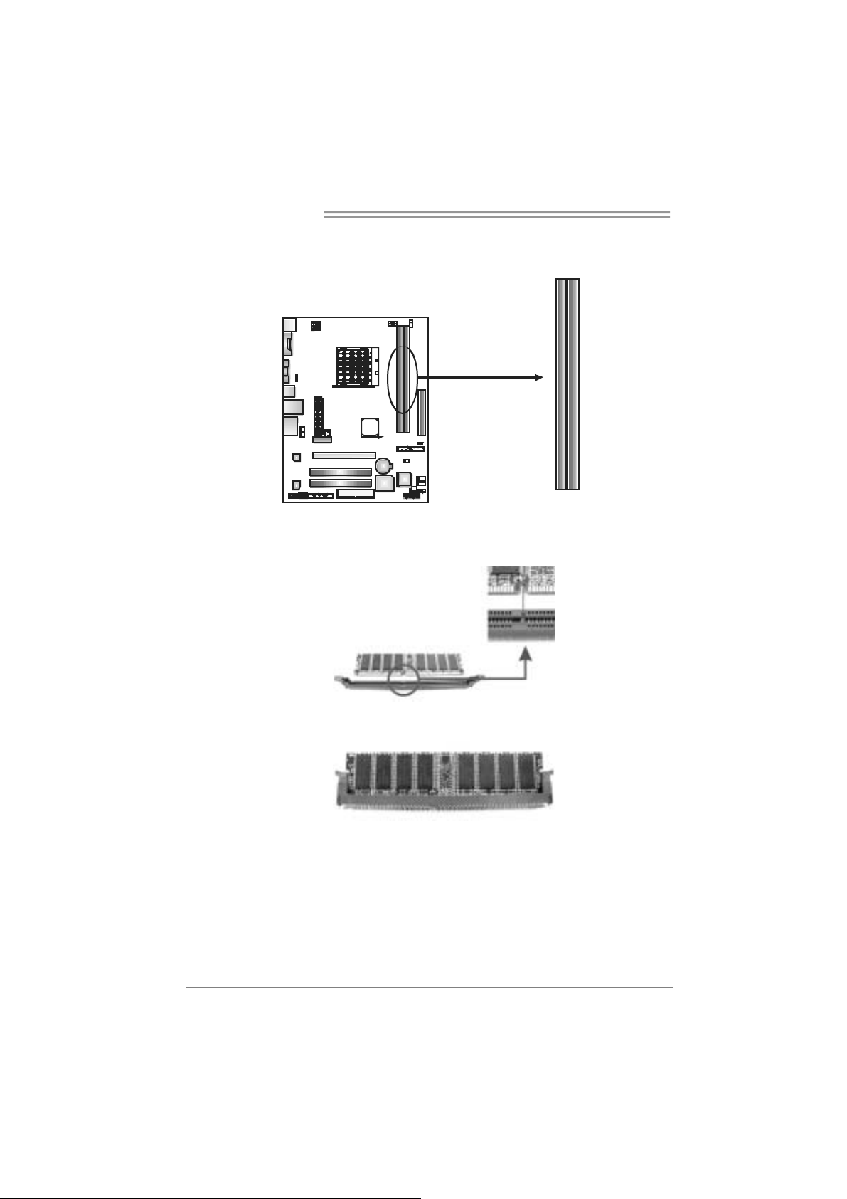
2.3 INSTALLING SYSTEM MEMORY
A. Memory Mo du le s
DIMMA1DIMMB
1. Unlock a DIMM slot by pressing the retai ning clips outward. Align a
DIMM on the sl ot such that the notch on the DIMM m atches the
break on the Slot.
2. Insert the DIMM vertically and firmly into the slot until the retaining
chip snap back in place and the DIMM is properly seated.
8
Page 11
NF61V Micro AM2 / NF61S Micro AM2
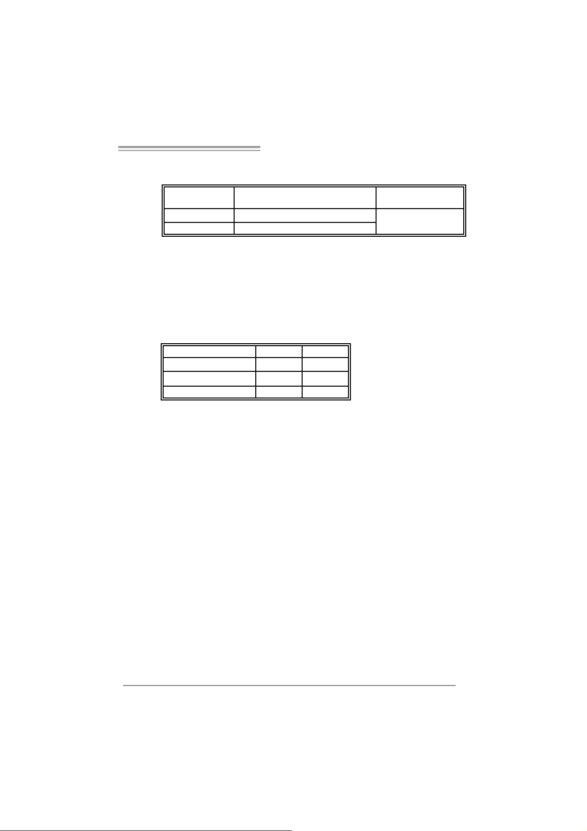
B. Memory Capacity
DI MM Socket
Location
DIMMA1 256MB/512MB/1024MB *1
DIMMB1 256MB/512MB/1024MB *1
C. Dual Channel Memory installation
To t rigger t he Dual Channel function of t he motherboard, the memory m odule
must mee t the following requirement s:
Install memory module of the sam e density in pair, shown in the following table.
Du al Channel Statu s
Disabled O X
Disabled X O
Enabled O O
(O means memory installed, X m eans memory not installed.)
The DRAM bus width of the memory m odul e must be the same (x8 or
x16)
DDR Module Total Memory Size
Max memory 2GB.
DIMMA 1
DIMMB1
9
Page 12
Motherboard Manual
2.4 CONNECTORS AND SLO TS
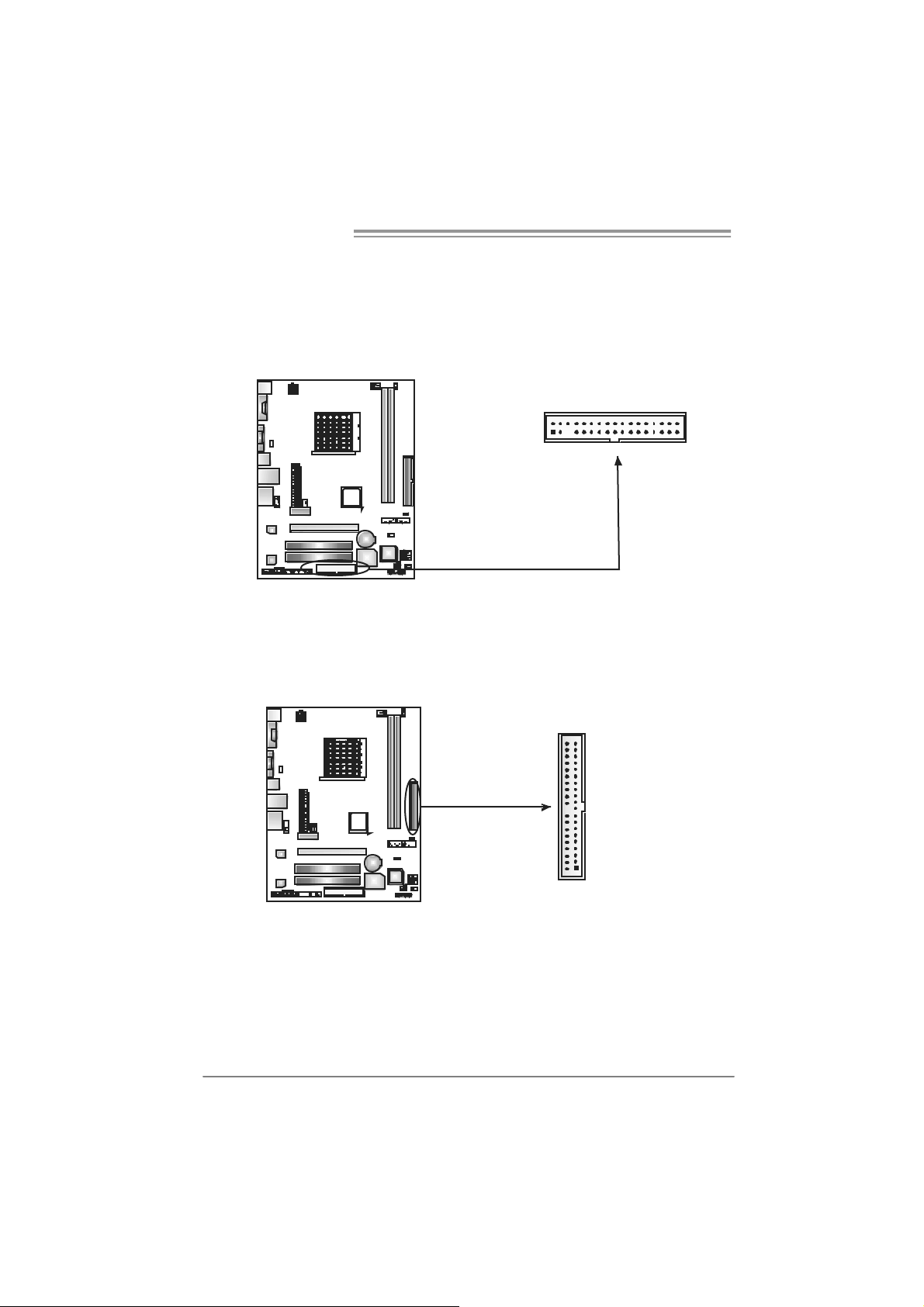
FDD1: Flo ppy Disk Connector
The motherboard prov ides a standard floppy disk connector that supports 360K,
720K, 1. 2M, 1.44M and 2. 88M floppy disk types. This connect or supports the
provided f loppy drive ribbon cables.
2
133
34
IDE1: Hard Disk Conn ector
The motherboard has a 32-bit Enhanced IDE Controller that provides PIO Mode
0~4, Bus Mast er, and Ult ra D MA 33/ 66/100/133 f unctionality.
The IDE connector can connect a mast er and a s lave drive, so you can connect
up to two hard dis k drives.
40
39
10
1
2
Page 13
NF61V Micro AM2 / NF61S Micro AM2
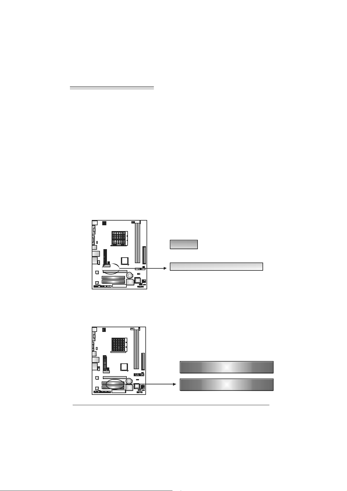
PCI-Ex1_1: P CI- Expr es s x1 S l ot
- PC I -Ex press 1.0a compliant.
- D at a transfer bandwidth up to 250MB/s per direc t ion; 500MB/s in total.
- PC I -Ex press supports a raw bit-rate of 2.5Gb/s on the data pins.
- 2X bandwidth over the tradit ional PCI architecture.
PCI-Ex16: PCI-Express x16 Slot (x1 Speed)(for NF61V MIC RO
AM2)
- PC I -Ex press 1.0a compliant.
- Maxim um theoretical realized bandwidth of 250MB/s sim ultaneous ly per
direct ion, for an aggregat e of 500MB/s totally.
PCI-Ex16: PCI-Express x16 Slot (x8 Speed)(for NF61S MICRO
AM2)
- PC I -Ex press 1.0a compliant.
- Maxim um theoretical realized bandwidth of 2GB/s simult aneously per
direct ion, for an aggregat e of 4GB/s totally.
PCI-EX1_1
PCI-EX16
PC I1~PCI2: Pe riphe ral Componen t In terconnect Slots
This mot herboard is equipped with 2 standard PCI slots. PCI stands for
Peripheral Com ponent Int erconnect, and it is a bus standard for expansion
cards . This PCI slot is designated as 32 bits.
PCI1
PCI2
11
Page 14
Motherboard Manual
CHAPTER 3: HEADERS & JUMPERS SETUP
3.1 HOW TO SETUP JUMPERS
The illustration shows how to set up jumpers. When the jumper cap is
placed on pins, the jumper is “close”, if not, that means the jumper is
“open”.
Pin opened Pin closed Pin1-2 closed
3.2 DETAIL SETT INGS
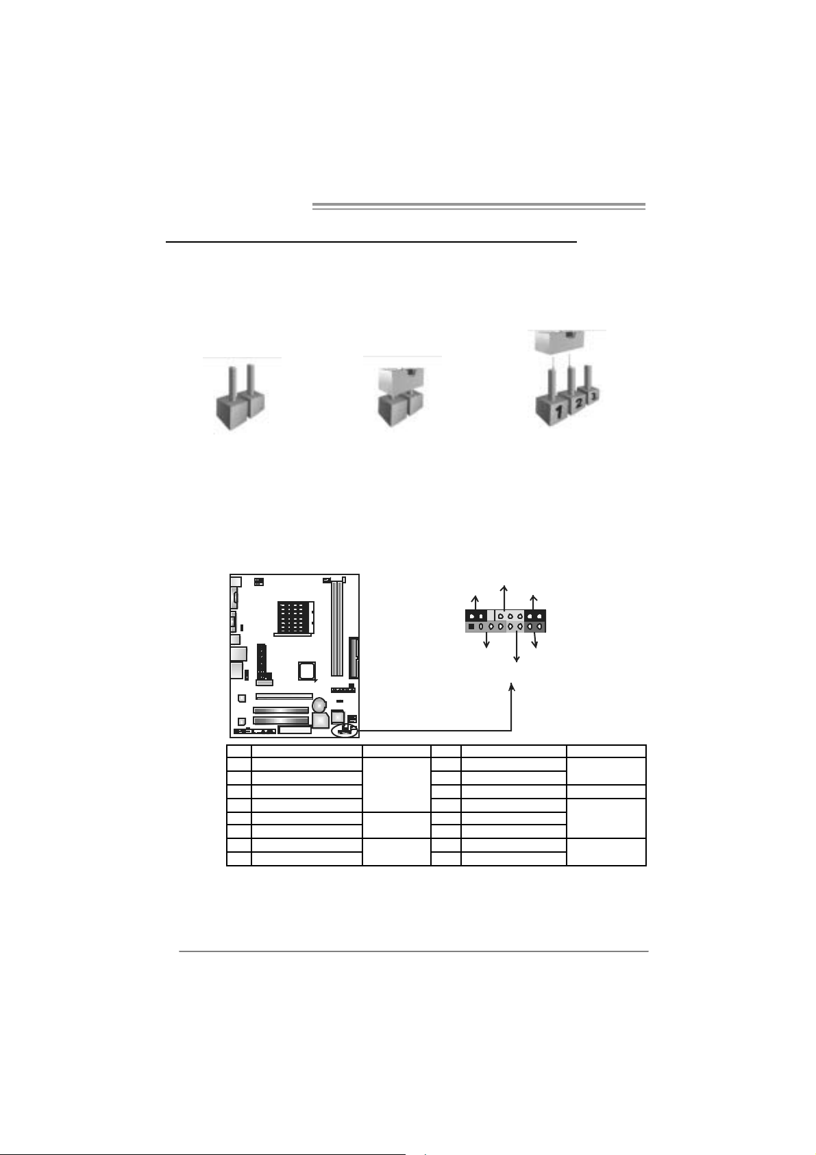
JPANEL1: Front Panel Header
This 16-pin connector includes Power-on, Reset, HDD LED, Power LED, Sleep
butt on and speaker connection. It allows user to connect the PC case’s f ront
panel switch functions.
D
E
L
_
R
W
P
S
L
P
+
2
1
+
+
K
P
S
H
f
f
O
/
n
O
-
16
15
-
T
S
R
D
E
L
12
Pin Assignment Function Pin Assignment Functio n
1 +5V 9 Sleep control
2 N/A 10 Ground
3 N/A 11 N/A N/A
4 Speaker
5 HDD LED (+) 13 Power LED (+)
6 HDD LED (-)
7 Ground 15 Power button
8 Reset control
Speaker
Connector
Hard drive
LED
Reset button
12 Pow er LED (+)
14 Pow er LED (-)
16 Ground
Sleep button
Powe r LED
Power-on button
Page 15
NF61V Micro AM2 / NF61S Micro AM2
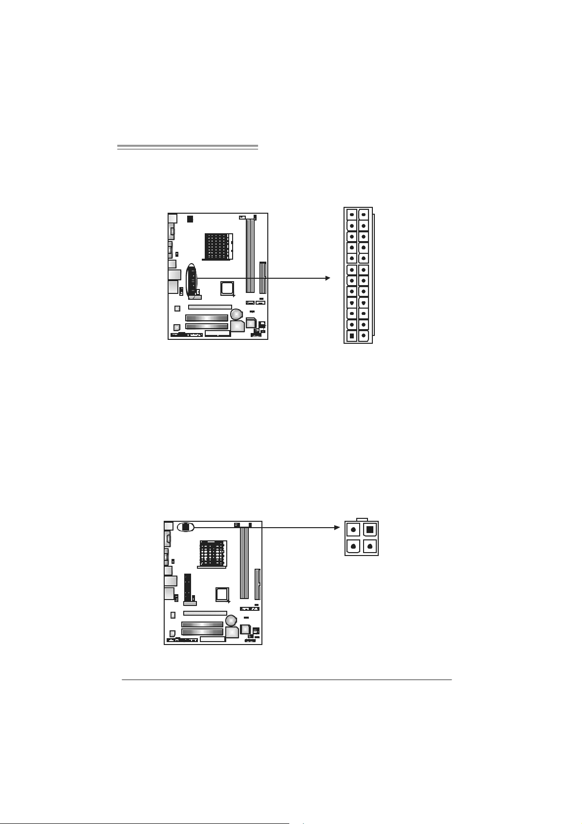
JATXPW R1: ATX Powe r Source Connector
This connector allows user to connect 24-pin power connector on the ATX
power supply.
12
1
Pin Assignment Pin Assignment
24
13
13 +3.3V 1 +3.3V
14 -12V 2 +3.3V
15 Ground 3 Ground
16 PS_ON 4 +5V
17 Ground 5 Ground
18 Ground 6 +5V
19 Ground 7 Ground
20 NC 8 PW_OK
21 +5V 9 Standby Voltage+5V
22 +5V 10 +12V
23 +5V 11 +12V
24 Ground 12 +3.3V
J ATXPWR2: ATX Power Sou rce Connector
By c onnecting this connector, it will provide +12V to CPU power circ uit.
12
Pin
34
1 +12V
2 +12V
3 Ground
4
Assignment
Ground
13
Page 16
Motherboard Manual
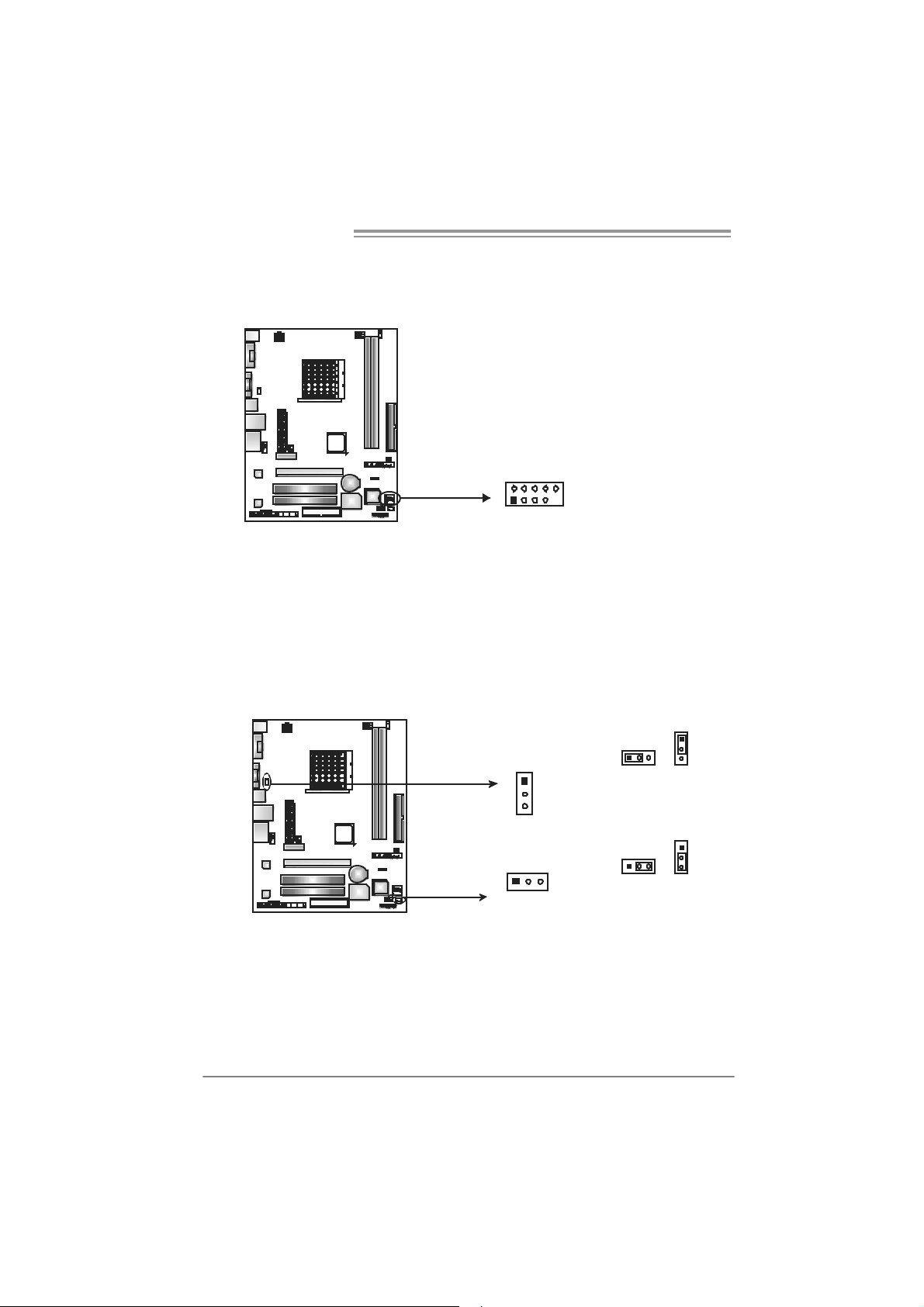
JUSB2/JUSB3: Headers for USB 2.0 Ports at Front Panel
This header allows user to connect additional USB cable on the PC front panel,
and also can be connected with internal USB devic es, like USB card reader.
JUSB2 JUSB3
210
1
JUS B V1/JUSBV2: Powe r Source Headers f or USB P ort s
Pin 1- 2 Close:
JU SBV1: +5V for USB ports at JUSBLAN 1.
JU SBV2: +5V for USB ports at f ront panel (JUSB2/JUSB3).
Pin 2- 3 Close:
JU SBV1: USB ports at JU SBLAN1 are powered by +5V st andby volt age.
JU SBV2: USB ports at front panel (JUSB2/JUSB3) are powered by +5V
standb y vol tage.
Assignment
Pin
1 +5V (fused)
2 +5V (fused)
3 USB4 USB5 USB+
6 USB+
7 Ground
8 Ground
9 Key
9
10 NC
14
JUSBV1
1
3
13
JUSBV2
13
Pin 1-2 close
13
Pin 2-3 close
1
3
1
3
Note:
In order to support this function “Power-On s ystem via USB device,” “JUSBV1/ JUSBV2”
jumper cap should be placed on Pin 2-3 indi v idually.
Page 17
NF61V Micro AM2 / NF61S Micro AM2
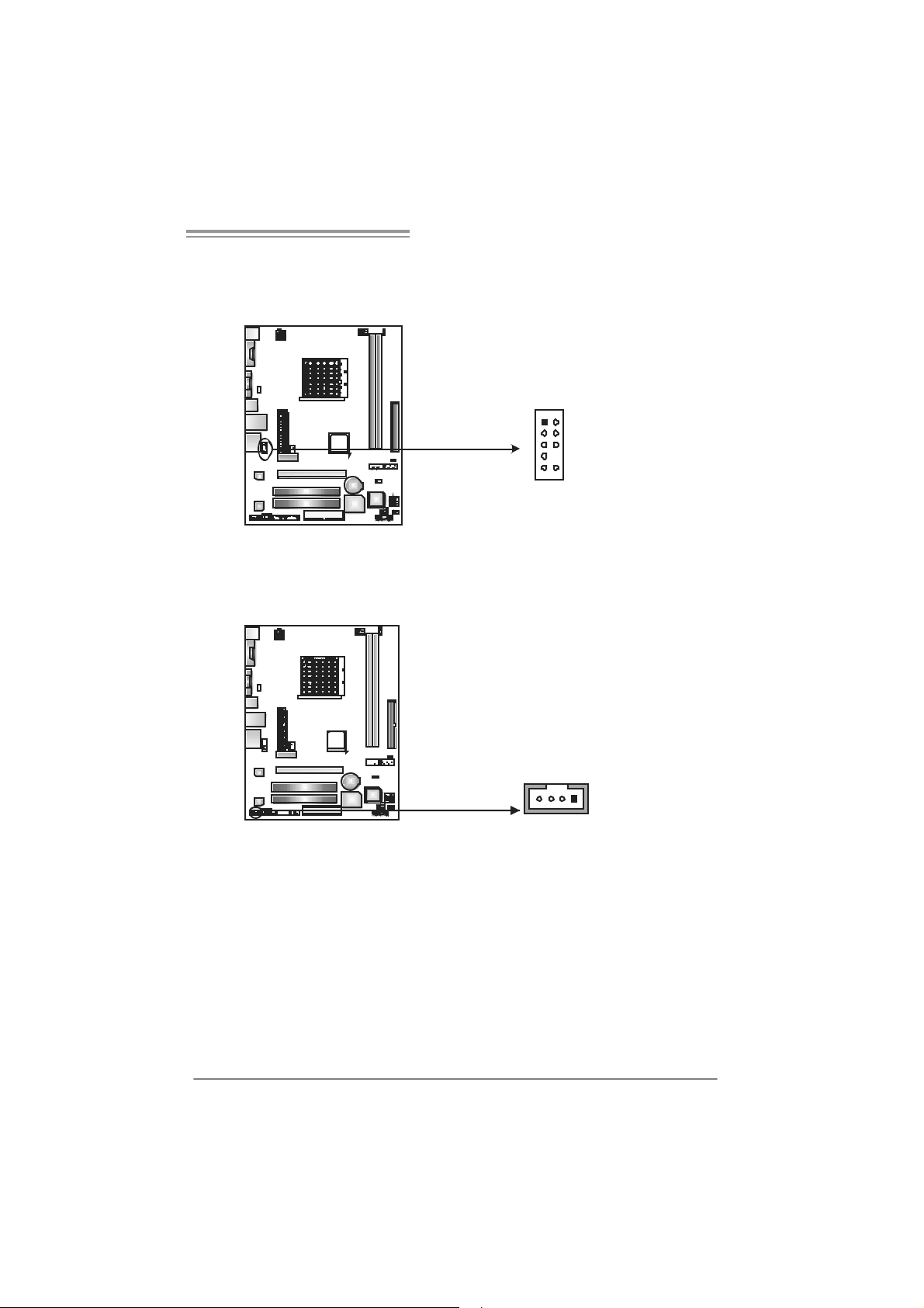
JAUDIOF1: Fron t Panel Audio Header
This header allows user to connect the front audio out put cable with the PC front
panel. It will disable the output on back panel audio c onnectors.
Pin Assignment
1 Mic in
2 Ground
3 Mic power
4 Audio power
5 Right line
1
9
2
10
JCDIN1: CD-R OM A ud i o-in Connector
This connector allows user to connect the audio sourc e from the variaty devices,
like CD-R OM, DVD-ROM, PCI sound card, PCI TV turner card etc.
14
out
6 Ground
7 Reserved
8 Key
9 Left line out
10 Ground
Assignment
Pin
1 Left Channel
Input
2 Ground
3 Ground
4 Right Channel
Input
15
Page 18
Motherboard Manual
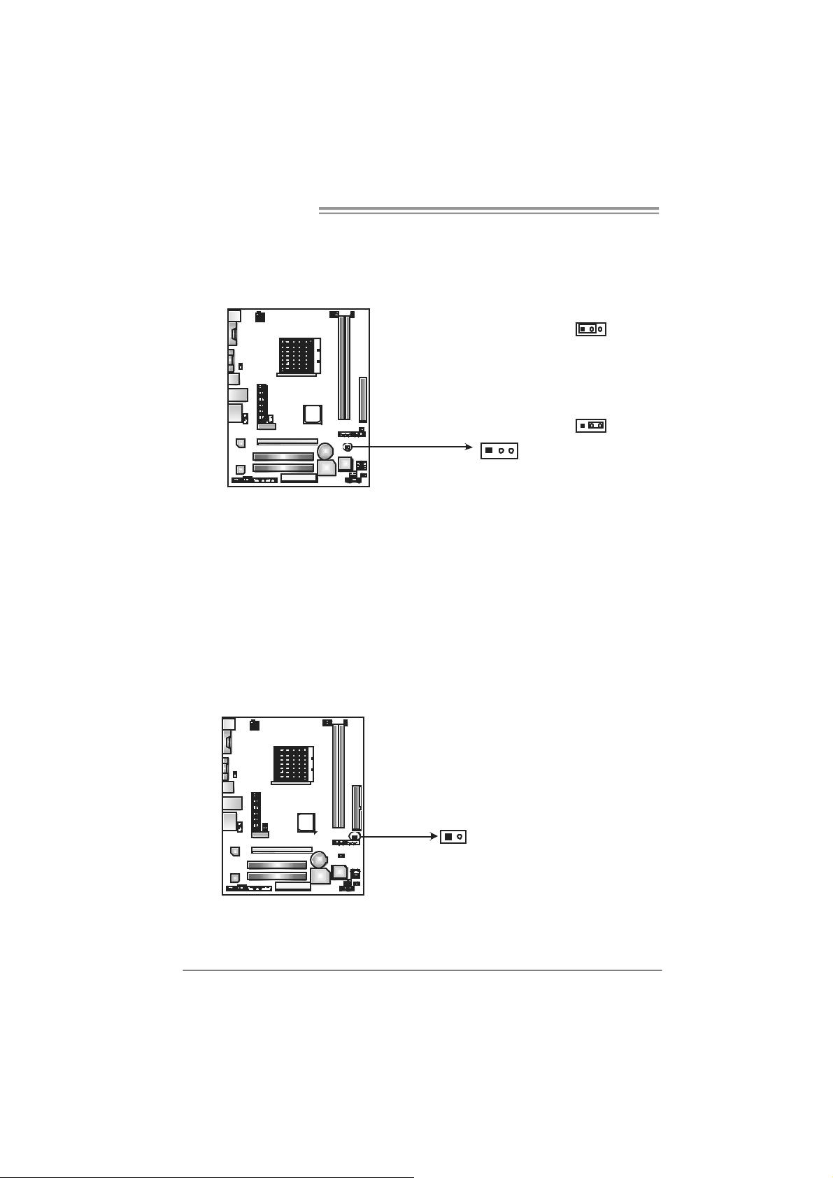
JCMOS 1 : C lear CMOS H eader
By plac ing the jumper on pin2-3, it allows user to restore the BIOS saf e sett ing
and the CMOS dat a, please carefully f ollow the procedures to avoid damaging
the m otherboard.
※ Clear CMOS Procedures:
1. Rem ov e AC power line.
2. Set the jumper to “Pin 2-3 close”.
3. Wai t for fi ve se co n ds.
4. Set the jumper to “Pin 1-2 close”.
5. Power on the AC.
6. Res et your desired pas s word or clear the CMOS data.
13
Pin 1-2 Close:
Normal Operation
(default).
3
1
Pin 2-3 Close:
Clear CMOS
data.
13
JCI1: Chassis Open Header (Optional)
This connector allows system to monitor PC case open stat us. If the signal has
been triggered, it will record to the CMOS and show the message on next
boot-up.
16
Pin
Assignment
1 Case open
si gnal
1
2
2 Ground
Page 19
NF61V Micro AM2 / NF61S Micro AM2
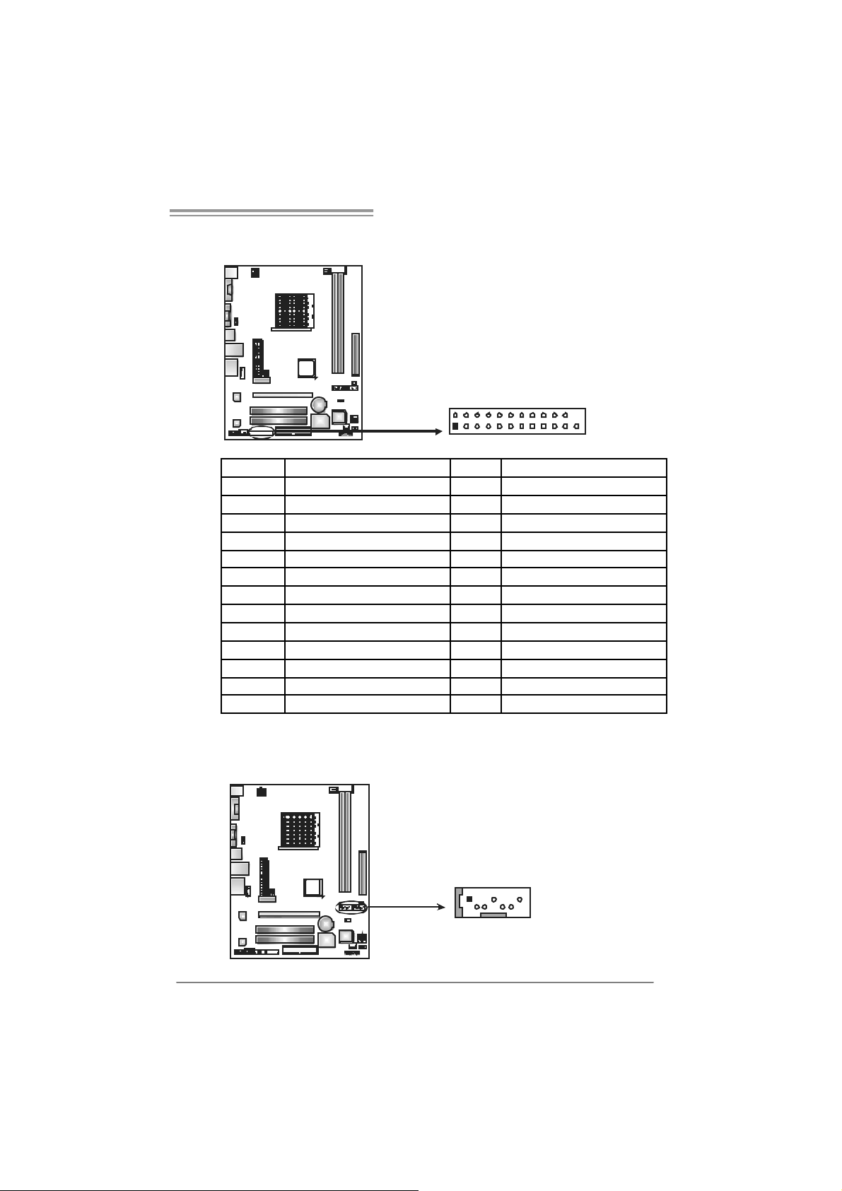
JPRNT1: Printer Port Con nector
This header allows you to connector printer on the PC.
2
1
25
Pin Assignment Pin Assignment
1 -Strobe 14 Ground
2 -ALF 15 Data 6
3 Data 0 16 Ground
4 -Error 17 Data 7
5 Data 1 18 Ground
6 -Init 19 -ACK
7 Data 2 20 Ground
8 -Scltin 21 Busy
9 Data 3 22 Ground
10 Ground 23 PE
11 Data 4 24 Ground
12 Ground 25 SCLT
13 Data 5
JSATA1~JS ATA2: Serial ATA Connecto rs
The motherboard has a PCI to SATA Controller with 2 channels SATA interface,
it satisfies the SATA 2.0 spec and with transfer rate of 3.0Gb/s.
Pin
Assignment
1 Ground
2 TX+
3 TX-
14 7
4 Ground
5 RX6 RX+
7 Ground
JSATA1 JS ATA2
17
Page 20
Motherboard Manual
Header for Me mor y over-voltage: JD DR I I_22V 1
When proc essing Memory over-voltage, please place the jumper to pin2-3
Clos ed. The D ef ault setting is Pin 1-2 C los ed.
1
3
Norm al s tat us ( default).
Mem or y v oltage 2. 2V.
1
3
Pin 1- 2 Cl os e:
1
3
Pin 2- 3 Cl os e:
Note:
1. When “JDDRII_2. 2V” jumper cap is placed on Pin 1-2, memory voltage
can be manually adjusted in CMOS s et up screen.
2. When “JDDRII_2. 2V” jumper cap is placed on Pin 2-3, memory voltage
will be f ix ed at 2.2V automatically, and can’t be adjusted under COMS
setup.
Before setting memor y over- vol tage, please ensure that your DDR2 supports up
to 2.2V. ( Consult your DDR2 supplier)
JSP DIF_O UT1: Digital Audio-out Con n ec tor
This connector allows user to connect the PCI brack et SPDIF output header.
Pin
Assignment
1 +5V
2 SPDIF_OUT
3 Ground
18
13
Page 21
NF61V Micro AM2 / NF61S Micro AM2
CHAPTER 4: RAID FUNCTIONS
4.1 OPERATION SYSTEM
Supports Windows XP H om e/Professional Edition, and Windows 2000 Prof essional.
4.2 RAID ARRAYS
RAI D supports the following types of R AID array s :
RAID 0: RAID 0 defines a disk striping scheme that improves disk read and write times for
many applications.
RAID 1: RAID 1 defines t echniques for mirroring data.
4.3 HOW RA ID WORKS
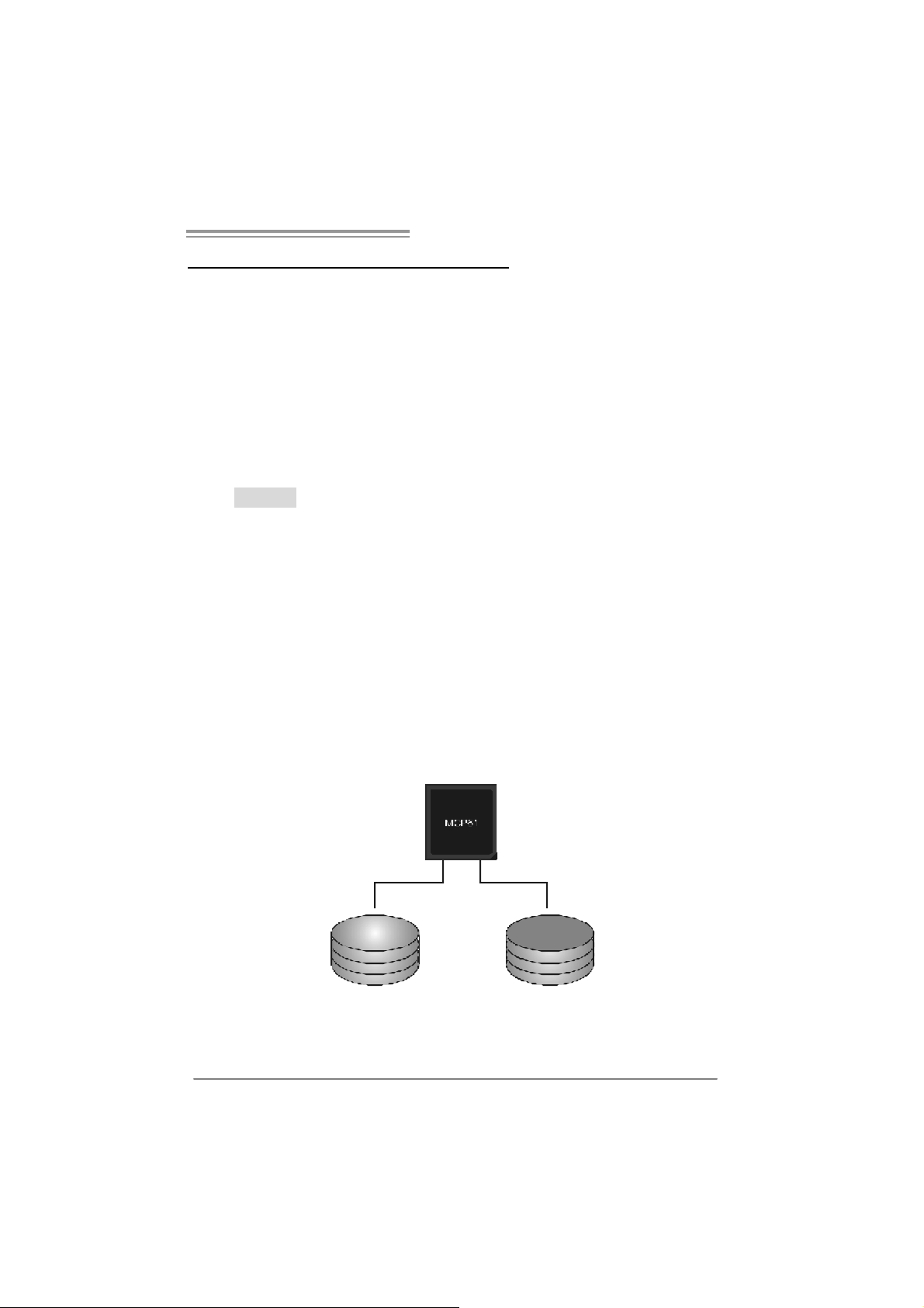
RAID 0:
The controller “stripes” data across multiple d rives in a RA ID 0 array system. It breaks
up a large file into smaller blocks and performs disk reads and writes across multiple
drives in parallel. The size of each block is determined by the stripe size parameter,
which you set during the creation of the RAID set based on the system environment. This
technique reduces overall disk access time and o ffers high bandwidth.
Fea tures and Be nefits
Drives: Minimum 1, and maximum is up to 6 or 8. Depending on the
platform.
Uses: Intended for non-crit ical data requiring high dat a throughput, or any
environment that does not require fault toleranc e.
Benefits: provides increas ed dat a throughput, espec ially f or large f iles. No
capac ity loss penalty for parity.
Drawbacks: Does not deliver any fault tolerance. If any drive in the array
fails, all dat a is lost.
Fa ult To le ranc e : No.
Blo c k 1
Bl o ck 3
Bl o ck 5
Bl o ck 2
B lock 4
B lock 6
19
Page 22
Motherboard Manual
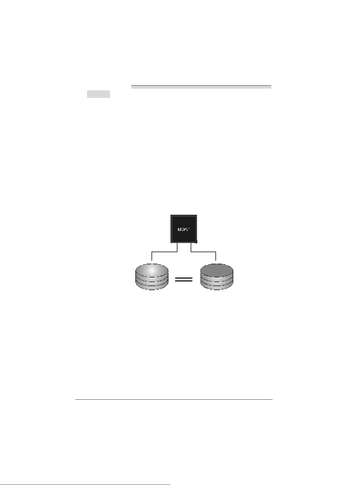
RAID 1:
Every read and write is actually carried out in p arallel across 2 disk d rives in a RA ID 1
array system. The mirrored (backup) copy of the data can reside on the same disk or on
a second redundant drive in the array. RAID 1 provides a hot-standby copy of data if
the active v olume or dri ve is corrupted or becomes unavailable because of a hard ware
failure.
RAID techniques can be applied for high-availability solutions, or as a form of
automatic backup that eliminates tedious manual backups to more expensive and less
reliable media.
Fea tures and Be nefits
Drives: Minimum 2, and m ax imum is 2.
Uses: RAID 1 is ideal for small dat abas es or any other applicat ion t hat
requires f ault tolerance and minimal ca paci t y.
Benefits: Prov ides 100% data redundancy. Should one driv e fail, the
controller switche s to the other dri ve.
Drawbacks: Requires 2 driv es for the storage space of one driv e.
Performance is impaired during driv e rebuilds.
Fault To le rance : Yes.
20
Blo c k 1
Bl o ck 2
Bl o ck 3
Block 1
Bl o ck 2
Bl o ck 3
Page 23
NF61V Micro AM2 / NF61S Micro AM2
CHAPTER 5: USEFUL HELP
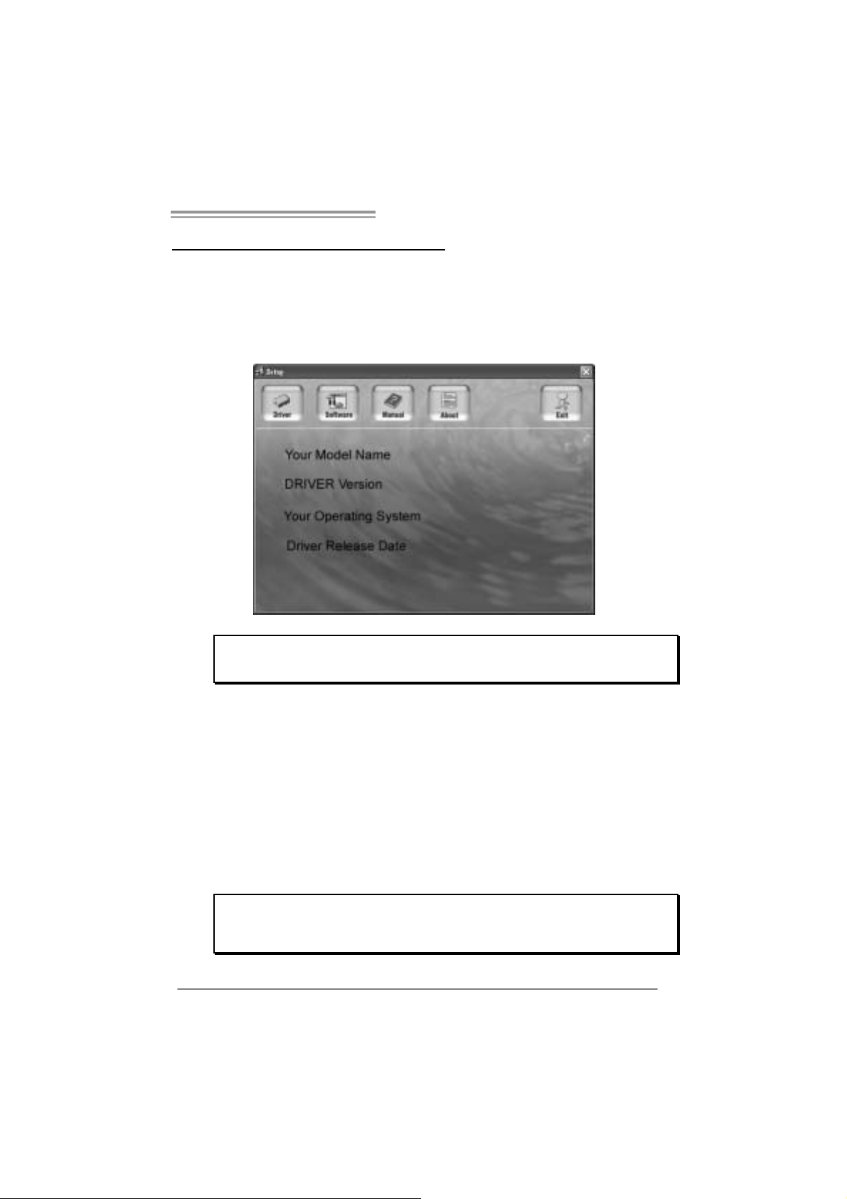
5.1 DRIVER INSTALLATION NOTE
After you installed your operating system, please insert the Fully Setup
Dri ver CD into your optical drive and install the driver for better system
performance.
You will see the following window after you insert the CD
The set up guide will auto d et ect yo ur motherboard and o pe rati ng system.
Note:
If this window didn’t show up after you insert the Driver CD, please use file browser to
l ocate an d e xecu te t h e fi l e SETU P.EXE under yo ur o pti c al dr i ve.
A. Driver Install ation
To install the driver, pl ease click on the Driver icon. The setup guide will
list the compatibl e driver for your motherboard and operating system.
Click on each devi ce driver to launch the installation program.
B. Software Installatio n
To install the software, please click on the Software icon. The setup guide
will list the software available for your system, click on each software title
to la unch th e ins tallat io n pr ogr a m.
C. Manual
Asi de from the paperback manual, we also provide manual in the Driver
CD. Click on the Manual icon to browse for availabl e manual.
Note:
You will need Acrobat Reader to open the man ual file. Plea se dow nloa d the la te s t ve rs ion
of Acrobat Reader software from
http://www.adobe.com/products /a crobat/readstep2.html
21
Page 24
Motherboard Manual
5.2 AWARD BIOS BEEP CODE
Beep Sound Meanin g
One long beep followed by t wo s hort
beeps
High-low siren sound CPU overheated
One Short beep when system boot-up N o error found during POST
Long beeps every ot her second No DRAM detected or ins t all
Video card not found or video card
mem ory bad
Sys t em will s hut down automat ic ally
5.3 EXT RA INFORMATION
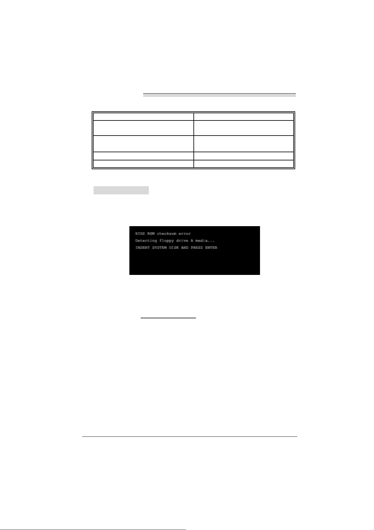
A. BIOS Update
After yo u fail to update B IOS or BIOS is invaded by vi rus, the
Boot-Block function will help to restore BIOS. If the following message
is shown after boot-up the system, it means the BIOS contents are
corrupted.
In thi s Case, please follow the procedure below to restore the BIOS:
1. Mak e a bootab le floppy d is k.
2. Download the Flash Uti lity “AWDFLASH.exe” from the Biostar
website: www.biostar.com.tw
3. Confirm motherboard model and download the respecti vely BIOS
fr om Bi os t ar websit e.
4. Copy “AWDFLASH.exe” and respectively BIOS into floppy disk.
5. Insert the bootable disk into floppy drive and press Enter.
6. Syste m will boot-u p to DOS prompt.
7. Type “Awdflash xxxx.bf/sn/py/ r” in DOS prompt.
(xxxx means BIOS name.)
8. Syste m will update BIOS au to matic ally and restart.
9. The BIO S h as been re covered and will work properly.
22
Page 25

NF61V Micro AM2 / NF61S Micro AM2
B. CPU Overheated
If the system shutdown automati cally after power on system for
seconds, that means the CPU protection function has been acti vated.
When the CPU is over heated, the motherboard will shutdown
automati cally to avoid a damage of the CPU, and the system may not
power on again.
In thi s case, please double check:
1. The CPU cooler surface i s placed evenly with the CPU surface.
2. CPU fan is rotated normally.
3. CPU fan speed i s fulfilling with the CPU speed.
After confirmed, please follow steps below to relief the CPU protection
function.
1. Remove the power cord from power supply for seconds.
2. Wait for secon ds.
3. Plug in the power cord and boot up the system.
Or you can:
1. Clear the CMOS data.
(See “Close CMOS Header: JCMOS1” section)
2. Wait for secon ds.
3. Pow er on th e system again.
23
Page 26
Motherboard Manual
e
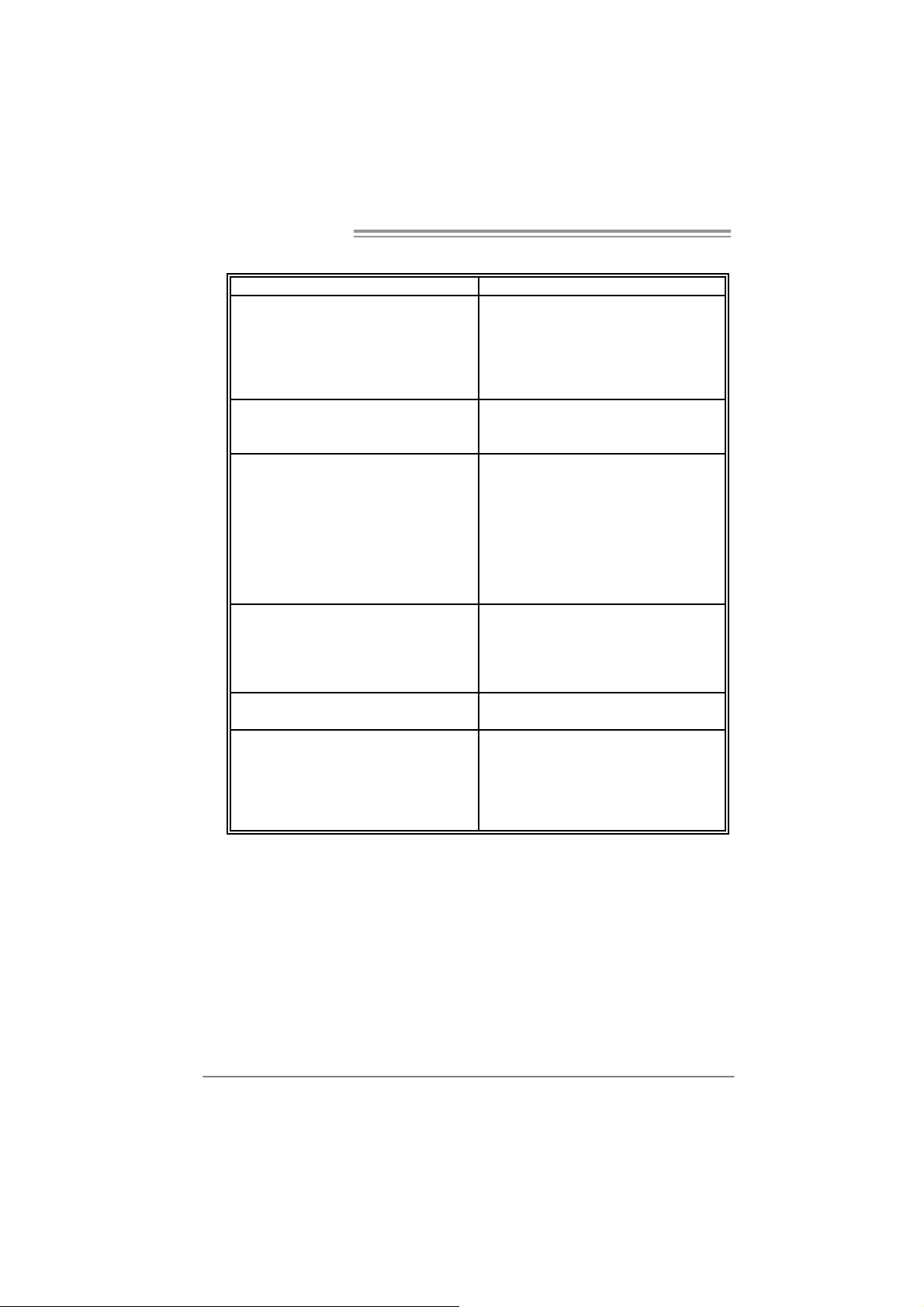
5.4 TROUBLESHOOTING
Probable Solution
1. No power to the system at all
Power light don’t illuminate, fan
inside power supply does not turn
on.
2. Indic at or light on k ey board does
not t urn on.
Sys t em inoperativ e. Keyboard lights
are on, power indicat or lights are lit,
and hard drive is spinning.
Sys t em does not boot from hard disk
drive, can be booted f rom optic al driv e.
Sys t em only boots from optical driv e.
Hard disk can be read and applications
can be used but booting from hard disk
is imposs ible.
Screen m essage says “Invalid
Conf igurat ion” or “C MOS Failure.”
Cannot boot syst em aft er installing
sec ond hard driv e.
1. Make s ure power cable is
sec urely plugged in.
2. Replace cable.
3. Contact techni cal support.
Us ing even press ure on bot h ends of
the DIMM, press down f irm ly until the
module s naps into place.
1. Chec k cable running from disk to
disk controller board. Make sure
both ends are sec urely plugged
i n; c hec k the driv e t y pe in the
standard CMOS se tup.
2. Back ing up the hard driv e is
ext rem ely import ant. All hard
disk s are capable of breaking
down at any t ime.
1. Back up data and applic at ions
files.
2. Reformat the hard drive.
Re-ins t all applications and data
using backup disks.
Rev iew syst em’s equipment. Make sur
correc t information is in setup.
1. Set m ast er/slave jumpers
correctly.
2. Run SETUP program and select
correc t drive types. Call the drive
manufacturers for compatibilit y
with other drives.
24
Page 27

NF61V Micro AM2 / NF61S Micro AM2
CHAPTER 6: WARPSPEED ER™
6.1 INTRODUCTION
[WarpSpeeder™], a new powerful control utility, features three
user-friendly functions includi ng Overclock M anager, Overvol tage
Manager, and Hardware Monitor.
With the Overclock Manager, users can easil y adjust the frequency they
prefer or they can get the best CPU performance with just one click. The
Overvoltage Manager, on the other hand, helps to power up CPU core
vol tage and Me mor y v ol tage. Th e co ol Har dw are Mo ni tor s martly indicates
the temperatures, voltage and CPU fan speed as wel l as the chipset
information. Also, in the About panel, you can get detail descripti ons about
BIOS model and chipsets. In addition, the frequency status of CPU,
memory, AGP and PCI along with the CPU speed are synchronically
s how n on our ma i n p an el .
Moreover, to protect users' computer systems if the setting is not
appropriate when testing and results in system fail or hang,
[WarpSpeeder™] technology assures the system stability by autom atically
rebooting the computer and then restart to a speed that is either the
original system speed or a suitable one.
6.2 SYSTEM REQU IREMENT
OS Support: Windows 98 SE, Windows Me, Wi ndows 2000, Windows XP
DirectX: DirectX 8.1 or above. (The Windows XP operating system
includes DirectX 8.1. If you use Windows XP, you do not need to install
Dir ec tX 8.1.)
25
Page 28

Motherboard Manual
6.3 INSTALLATION
1. Execute the setup execution file, and then the following dialog will pop
up. Please click “Next” button and follow the default procedure to
install.
2. When you see the following dialog in setup procedure, i t means setup
is completed. If the “Launch the WarpSpeeder Tray Utility” checkbox
is che c ked, the Tray Ic on utility and [WarpSpeeder™] utility will be
automati cally and immediately launched after you click “Finish”
button.
26
Usage:
The following figures are just only for reference, the screen printed in
this user manual will ch an ge a c c ording to you r mothe rbo ard on hand.
Page 29

NF61V Micro AM2 / NF61S Micro AM2
6.4 WARPSPEEDER™
1. Tray Icon:
Whenever the Tray Icon utility i s launched, i t will displa y a little tra y
icon on the ri ght side of Windows Taskbar.
This utility is responsible for conveniently invoking [WarpSpeeder™]
Utility. You can use the mouse by clicking the left button i n order to
invoke [WarpSpeeder™] directly from the little tray i con or you can
right-click the little tray i con to pop up a popup menu as followi ng
figure. The “Launch Utility” item in the popup menu has the same
fun c tio n a s m ouse left-click on tray ic on an d “E xi t” item will close
T ray Icon utility if selected.
27
Page 30

Motherboard Manual
2. Main Panel
If y ou click the tra y icon, [WarpSpe ede r™] u tility will be i nvoked .
Please refer to the foll o wing figure; the utility’s fi rst wi ndow you will
see is Main Panel.
Main Panel contains feature s as foll ows:
a. Di splay the C PU Speed, CPU external clock, Memory cl ock, AGP cl ock,
and PCI clock information.
b. Contains About, Voltage, Overclock, and Hardware Monitor Buttons for
invoking respecti ve panels.
c. With a user- fr ie nd ly St at us A n imation, it c an r epr esent 3 ov er c l ock
percentage stages:
Man walking→overclock percentage from 100% ~ 110 %
Panther running→overclock percentage from 110% ~ 120%
Ca r rac ing →overclock percentage from 120% ~ above
28
Page 31

NF61V Micro AM2 / NF61S Micro AM2
3. Vol tage Panel
Click the Volta ge button in Main Panel, the b ut ton will be hig hligh ted
and the Vol ta ge Pa nel will slide out t o up as the f ollowing figure .
In thi s panel, you can decide to increase CPU core vol tage and
Memory voltage or not. The default setting is “No”. If yo u want to get
the best performance of overclocking, we recommend you click the
option “Yes”.
29
Page 32

Motherboard Manual
4. Over clock Panel
Click the O verclo c k button in Main Pane l, the button will be
highlighted and the Overclock Panel will slide out to left as the
fol l owi ng f igur e.
Overclock Panel cont ains the these fea tures:
a. “–3MHz button”, “-1MHz button”, “+1M Hz button”, and “+3MHz button”:
provide user the ability to do real-time overclock adjustment.
Warning:
Manually overclock is potentially dangerous, espec ially when t he
overclocking percentage is over 110 %. We st rongly recommend you
verify ev ery speed you overclock by c lick the Verify button. Or, you can
just click Auto overclock button and let [WarpSpeeder™] autom atic ally
gets the best result for you.
b. “Recovery Dialog button”: Pop up the following dialog. Let user sel ect
a restoring way i f system need to do a fail-safe reboot.
30
Page 33

NF61V Micro AM2 / NF61S Micro AM2
c. “Auto-overclock button”: User can click this button and
[Wa rpS peeder™] will se t the best an d sta ble performance and
frequency automatically. [WarpSpeeder™] utility will execute a
se ries of te sting un til syste m fail . Th en system will do fail-safe
reboot by using Watchdog function. After reboot, the
[WarpSpeeder™] utility will restore to the hardware defaul t
setting or load the verified best and stable frequency according
to the Recovery Dialog’s setting.
d. “Verify button”: User can click this button and [WarpSpeeder™]
will proceed a testing for current frequency. If the testing i s ok,
then the cu rrent freq uency will be saved into system registry. If
the testing fail, system will do a fail-safe rebooting. After reboot,
the [WarpSpeeder™] utility will restore to the h ard ware defau lt
setting or load the verified best and stable frequency according
to the Recovery Dialog’s setting.
Note:
Becaus e the testing programs, invok ed in Auto-overclock and Verify,
include D irectDraw, Direct3D and Direct Show tests, the Direct X 8.1 or
newer runtime library is required. And pleas e make sure your display
card’s color depth is High color (16 bit) or True color( 24/32 bit ) that is
required for Direct3D rendering.
5. Hardware Monitor Panel
Click the Hard ware Moni to r bu tton in Ma in Pane l, the button will be
highlighted and the Hardware Monitor panel will slide out to left as
the fo l lowing f ig ure.
In thi s panel, you can get the real-time status information of your
syste m. The informa tio n will be ref reshed every 1 second.
31
Page 34

Motherboard Manual
6. About Panel
Click the “about” button in Main Panel, the button will be highlighted
and th e About Pa ne l will s l id e out to up as the fo l lowing fig ur e.
In thi s panel, you can get model name and detail information in hints
of all the chipset that are related to overclocking. You can also get
the mainboard’s BIOS model and the Version number of
[WarpSpeeder™] utility.
32
Note:
Because the overclock, overvoltage, and hardware monitor features
are controlled by several separate chipset, [WarpSpeeder™] divide
these features to separate panels. If one chipset is not on board, the
correlative button in M ain panel will be disabled, but will not interfer e
other panels’ functions. This property can make [WarpSpeeder™]
utility more robust.
Page 35

NF61V Micro AM2 / NF61S Micro AM2
This page is intentionally left blank
33
Page 36

Motherboard Manual
yp
APPENDENCIES: SPEC IN OTHER LA NGUAGE
GERMAN
NF 61V M ICR O A M2 NF61S M ICRO A M 2
CPU
FSB
Chipsatz
Super E/A
Ar beitsspeic
her
Grafi k
IDE
SA TA II
LAN
Audi o-Code
c
Steckplätze
Onboard-A
nschluss
34
Sockel AM2
AM D Athlon 64 / At hlon 64 FX / Athlon 64 x2/
Sempron Prozess oren
Unterstützt Hyper Transport und Cool’n’Quiet
Unterstützt H
von bis zu 1 GHz
MC P61V ( GeFor ce 61 00- 400) MC P61S ( GeFor ce 61 00- 405)
ITE 8716F
Bi etet die häufig verwendeten alten Super
E/A-Funktionen.
Low Pin Count-Schnittstelle
DDR2 DIMM-Steckplätze x 2
Jede r DIMM unterst ützt 256/512MB & 1GB
DDR2.
M ax. 2GB A rbeit ss peic her
Dual-Kanal DDR 2 Speichermodul
Unt erstützt DDR2 400 / 533 / 667 / 800
registrierte
Integrierter MCP61V Chipsatz
Max. 256MB gemei nsam benutzt er
Videospeicher
Integrierter IDE-Controller
Ultra DMA 33 / 66 / 100 / 133 Bus Master-Modus
Unterstützt PIO-Modus 0~4,
I nt e gri ert e r S e ri al ATA - Con tr o ll e r
Datentransferrate bis zu 3Gb/s
Konform mit der SATA-Spezifikation Vers ion 2.0.
Realt ek 8201CL PHY
10 / 100 Mb/s Auto-Negotiation
ALC861
8-Kanal-Audioausgabe
Unterstützt Intel High-Definition Audio
PCI-St eckplatz x2 PCI-St eckplatz x2
PCI Express x16 Steckplatz (x1) x1 PC I Ex press x16 St ec kplatz (x8) x 1
PCI Express x 1-Steckplatz x1 PCI Express x 1-Steckplatz x1
Di ske tt enla ufwerkanschluss x1 Di skett enla ufwe rkansc hluss x1
IDE-Anschl uss x1 IDE-Anschl uss x1
SATA2-Anschluss x2 SATA2-Anschluss x2
erTransport mit einer Bandbreite
Sockel AM2
AM D Athlon 64 / At hlon 64 FX / Athlon 64 x2/
Sempron Prozess oren
Unterstützt Hyper Transport und Cool’n’Quiet
Unterstützt HyperTransport mit einer Bandbreite
von bis zu 1 GHz
ITE 8716F
Bi etet die häufig verwendeten alten Super
E/A-Funktionen.
Low Pin Count-Schnittstelle
DDR2 DIMM-Steckplätze x 2
Jede r DIMM unterst ützt 256/512MB & 1GB
DDR2.
M ax. 2GB A rbeit ss peic her
Dual-Kanal DDR 2 Speichermodul
Unt erstützt DDR2 400 / 533 / 667 / 800
registrierte
Integrierter MCP61S Chipsatz
Max. 256MB gemei nsam benutzt er
Videospeicher
Integrierter IDE-Controller
Ultra DMA 33 / 66 / 100 / 133 Bus Master-Modus
Unterstützt PIO-Modus 0~4,
I nt e gri ert e r S e ri al ATA - Con tr o ll e r
Datentransferrate bis zu 3Gb/s
Konform mit der SATA-Spezifikation Vers ion 2.0.
Realt ek 8201CL PHY
10 / 100 Mb/s Auto-Negotiation
ALC861
8-Kanal-Audioausgabe
Unterstützt Intel High-Definition Audio
Page 37

NF61V Micro AM2 / NF61S Micro AM2
NF 61V M ICR O A M2 NF61S M ICRO A M 2
Fronttafelanschluss x1 Fronttafelanschluss x1
Fr ont-Audioanschluss x1 Fr ont-Audioanschluss x1
CD-I N-A nschluss x1 CD- IN-Anschl uss x1
S/PDIF- Ausgangsansc hluss x1 S/PDIF- Ausgangsanschluss x1
CPU-Lüfter-Sockel x1 CPU-Lüfter-Sockel x1
System-Lüfter-Sockel x2 System-Lüfter-Sockel x2
"CMOS löschen"-Sockel x1 "CMOS l öschen"-Sockel x1
US B-Ansc hl uss x2 US B-Ansc hl uss x2
Druckeranschluss-Anschluss x1 Druckeranschluss-Anschluss x1
"Gehäuse offen"-S ockel(optional) x1 "Gehäuse offen"-Sockel(optional ) x1
Stromanschluss (24-polig) x1 Stromanschluss (24-polig) x1
Stromanschluss (4-polig) x1 Stromanschluss (4-polig) x1
Rückseiten-
E/A
Platinengrö
ße.
Sonderfunk
tionen
OS-Unterst
ützung
PS/2-Tastatur x1
PS/2-Maus x1
Serieller A nsc hl uss x 1
VGA-Anschluss x1
LAN-A nschluss x1
US B-Ansc hl uss x4
Audi oanschluss x6
205 mm (B) X 244 mm (L) 205 mm (B) X 244 mm (L)
NVIDIA nTunes
Unterstützt RAID 0 / 1
Wi ndows 2000 / XP
Biostar behält sich das Recht vor, ohne
Ank ündigung die U nterstützung für ein
Be triebssystem hinzuz ufügen oder zu entfer nen.
PS/2-Tastatur x1
PS/2-Maus x1
Serieller A nsc hl uss x 1
VGA-Anschluss x1
LAN-A nschluss x1
US B-Ansc hl uss x4
Audi oanschluss x6
NVIDIA nTunes
Unterstützt RAID 0 / 1
Wi ndows 2000 / XP
Biostar behält sich das Recht vor, ohne
Ank ündigung die U nterstützung für ein
Be triebssystem hinzuz ufügen oder zu entfer nen.
35
Page 38

Motherboard Manual
FRANCE
NF 61V M ICR O A M2 NF61S M ICRO A M 2
Socket AM2
Pr ocess eurs AM D At hlon 6 4 / At hl on 64 FX /
Athlon 64 x2/ Sempron
Prend en c harge Hyper Trans port et Cool’n’Quiet
Prend en charge Hyper Transport jusqu'à une
bande passante de1 GHz
ITE 8716F
Four nit la fonctionnalité de Super E/S
patrimoniales la plus utilisée.
Interface à faible compte de broches
Fentes DDR2 DIMM x 2
Chaque DIMM prend en char ge des DDR2 de
256/512 Mo et 1Go
Capacité mémoire maximale de 2 Go
Modul e de mémoire DDR2 à mode à double voie
Prend en char ge la DDR2 400 / 533 / 667 / 800
Integré dans la chipset MCP61S
Mémoire vi déo partagée maximale de 256 Mo
Contrôleur IDE intégré
Mode pri nc ipale de Bus Ultra DMA 33 / 66 / 100 /
133
Prend en c harge le mode PIO 0~4,
Cont r ôl eur Se rial ATA intégré :
Taux de transfert jusqu'à 3 Go/s.
Conforme à la spécific ation SATA Version 2.0
Realt ek 8201CL PHY
10 / 100 Mb/s négociation automatique
ALC861
Sortie audio à 8 voies
Prise en c harge de l'audio haute définition Intel
UC
Bus frontal
Chipset
Super E/S
Mémoire
principale
Graphiques
IDE
SA TA II
LAN
Codec audio
Connecteur
embarqué
36
Socket AM2
Pr ocess eurs AM D At hlon 6 4 / At hl on 64 FX /
Athlon 64 x2/ Sempron
Prend en c harge Hyper Trans port et Cool’n’Quiet
Prend en charge Hyper Transport jusqu'à une
bande passante de1 GHz
MC P61V ( GeFor ce 61 00- 400) MC P61S ( GeFor ce 61 00- 405)
ITE 8716F
Four nit la fonctionnalité de Super E/S
patrimoniales la plus utilisée.
Interface à faible compte de broches
Fentes DDR2 DIMM x 2
Chaque DIMM prend en char ge des DDR2 de
256/512 Mo et 1Go
Capacité mémoire maximale de 2 Go
Modul e de mémoire DDR2 à mode à double voie
Prend en char ge la DDR2 400 / 533 / 667 / 800
Integré dans la chipset MCP61V
Mémoire vi déo partagée maximale de 256 Mo
Contrôleur IDE intégré
Mode pri nc ipale de Bus Ultra DMA 33 / 66 / 100 /
133
Prend en c harge le mode PIO 0~4,
Cont r ôl eur Se rial ATA intégré :
Taux de transfert jusqu'à 3 Go/s.
Conforme à la spécific ation SATA Version 2.0
Realt ek 8201CL PHY
10 / 100 Mb/s négociation automatique
ALC861
Sortie audio à 8 voies
Prise en c harge de l'audio haute définition Intel
Fente PCI x2 Fente PCI x2
Sl ot PCI Express x16 (x 1) x1 Slot PCI Ex press x16 (x8) x1 Fentes
Slot PCI Express x 1 x1 Slot PCI Express x 1 x1
Connecteur de dis quette x1 C onnect eur de disquette x1
Connecteur IDE x1 Connect eur IDE x1
Connecteur SATA 2 x2 Connecteur SATA2 x2
Connecteur du panneau avant x1 Connec teur du panneau avant x1
Connecteur Audio du panneau avant x1 Connec teur A udio du panneau avant x1
Connec teur d'entrée CD x1 Connecteur d'entrée CD x1
Page 39

NF61V Micro AM2 / NF61S Micro AM2
NF 61V M ICR O A M2 NF61S M ICRO A M 2
Connecteur de sortie S/PDIF x1 Connecteur de sortie S/PDIF x1
Embase de ventilateur UC x1 Embase de ventilateur UC x1
Embase de ventilateur système x2 Embase de ventilateur système x2
Embase d'effacem ent CMO S x1 Embase d'effacement CMOS x1
Connecteur USB x2 C onnect eur USB x2
Connecteur de Port d'imprimante x1 Connecteur de Port d'imprimante x1
Embase d' ouverture de châssis(en option) x1 Embase d' ouverture de châssis(en option) x1
E/S du
panneau
arrière
Dim ensions
de la carte
Fonctionnali
tés
spéciales
Support SE
Connec teur d'alimentation x1
(24 broc hes)
Connec teur d'alimentation x1
(4 broches)
Clavier PS/2 x1
Souris PS/2 x1
Port s érie x1
Port VGA x1
Port LAN x1
Port USB x4
Fiche audio x6
205 mm (l) X 244 mm (H) 205 mm (l) X 244 mm ( H)
NVIDIA nTunes
Prise en c harge RAID 0 / 1
Wi ndows 2000 / XP
Biostar se réserve le droit d'ajouter ou de
supprimer le support de SE avec ou sans préavis.
Connec teur d'alimentation x1
(24 broc hes)
Connec teur d'alimentation x1
(4 broches)
Clavier PS/2 x1
Souris PS/2 x1
Port s érie x1
Port VGA x1
Port LAN x1
Port USB x4
Fiche audio x6
NVIDIA nTunes
Prise en c harge RAID 0 / 1
Wi ndows 2000 / XP
Biostar se réserve le droit d'ajouter ou de
supprimer le support de SE avec ou sans préavis.
37
Page 40

Motherboard Manual
gacy
gacy
/
/
ITALIAN
NF61V MICR O A M2 NF61S MICRO AM 2
Socket AM2
Processori AMD Athlon 64 / Athlon 64 FX
CPU
FSB
Chi ps et MC P61V ( GeForce 61 00- 400) MC P61S ( GeFor ce 61 00- 405)
Super I/O
Memoria
princi pale
Grafica
IDE
SATA II
LAN
Codec audio
Alloggi Alloggio PCI x2 Alloggio PCI x2
/ Athlon 6 4 x 2/ Sempr on
Suppor to di Hyper Tra nsport e
Cool’n’Quiet
Suppor to di Hyper Transp ort fi no a1 GHz
di larg hezz a di banda
ITE 871 6F
Fornisce le funzio nalità le
usate più comunemente.
Interfaccia LPC (Low Pin Count)
Al loggi DIMM DDR 2 x 2
Ci as cun DIMM s u pporta DDR 2
256/512MB e 1GB
Capacità massima della memoria 2GB
Modul o di m em ori a D DR2 a c anal e d oppi o
Supporto di DDR2 400 / 533 / 667 / 800
Integrat a nel Chipset MCP6 1V
La memoria video condivisa massima è di
256MB
Controller IDE integrato
Modalità Bus Master Ultra DMA 33
100 / 13 3
Suppor to modalità PIO Mode 0- 4
Controller Serial ATA integrato
Ve locit à di tr as fer im ento dei dati fi no a 3
Gb/s .
Compatibile specifiche SATA Versione
2. 0.
Realt ek 8201CL PHY
Negozi az i one automati c a 10 / 10 0 Mb /s
ALC861
Uscita audio 8 canali
Suppor to au dio High- Defi nit ion (HD )
Intel
Super I/O
Socket AM2
Processori AMD Athlon 64 / Athlon 64 FX
/ Athlon 6 4 x 2/ Sempr on
Suppor to di Hyper Tra nsport e
Cool’n’Quiet
Suppor to di Hyper Transp ort fi no a1 GHz
di larg hezz a di banda
ITE 871 6F
Fornisce le funzio nalità le
usate più comunemente.
Interfaccia LPC (Low Pin Count)
Al loggi DIMM DDR 2 x 2
Ci as cun DIMM s u pporta DDR 2
256/512MB e 1GB
Capacità massima della memoria 2GB
Modul o di m em ori a D DR2 a c anal e d oppi o
Supporto di DDR2 400 / 533 / 667 / 800
Integrat a nel Chipset MCP6 1S
La memoria video condivisa massima è di
256MB
Controller IDE integrato
Modalità Bus Master Ultra DMA 33
66 /
100 / 13 3
Suppor to modalità PIO Mode 0- 4
Controller Serial ATA integrato
Ve locit à di tr as fer im ento dei dati fi no a 3
Gb/s .
Compatibile specifiche SATA Versione
2. 0.
Realt ek 8201CL PHY
Negozi az i one automati c a 10 / 10 0 Mb /s
ALC861
Uscita audio 8 canali
Suppor to au dio High- Defi nit ion (HD )
Intel
Super I/O
38
66 /
Page 41

NF61V Micro AM2 / NF61S Micro AM2
gg
gg
pp
NF61V MICR O A M2 NF61S MICRO AM 2
Al loggio PC I Expr es s x1 6 (x 1) x1 Al loggio PC I Expr es s x1 6 (x 8) x1
Al loggio PC I Expr es s x1 x1 Alloggio PC I Expres s x1 x1
Connettore flo ppy x1 Connet tore flo ppy x1
Connettore IDE x1 C onnett or e IDE x1
Connettore SATA2 x2 Connettore SATA2 x2
Connettore pa nnello fro ntale x1 Conne ttore pannello fro nt al e x1
Connettore audio frontale x1 Connettore audio frontale x1
Connettore CD-in x1 Connettore CD-in x1
Connettore output SPDIF x1 Connettore output SPDIF x1
Connettori su
scheda
I/O pannello
posteriore
Dim ens i oni
scheda
Caratteristic he
speciali
Sistemi
operativi
supportati
Collettore ventolina CPU x1 Collettore ventolina CPU x1
Collettore ventolina sistema x2 Collettore ventolina sistema x2
Collettore cancellazione CMOS x1 Collettore cancellazione CMOS x1
Connettore USB x2 C onnett or e USB x2
Connettore Port a s t am pa nte x1 Conne ttore Port a s t am pa nt e x1
Collettore apertur a telaio(optional) x1 Collettore apertura telaio(optional) x1
Connettore alimentazione x1
(24 pin)
Connettore alimentazione x1
(4 pin)
Ta s t ie r a P S / 2 x 1
Mouse PS/2 x1
Porta seriale x1
Porta VGA x1
Porta LAN x1
Porta USB x4
Connettore audio x6
205 mm (larghezza) x 244 mm (altezza) 205 mm (larghezza) x 244 mm (altezza)
nTu nes NV I DIA
Suppor to RA ID 0 / 1
Windows 2000 / XP
Biostar si riserva il diritto di a
rimuovere il supporto di qualsiasi sistema
operativo s e nza pre avviso.
iungere o
Connettore alimentazione x1
(24 pin)
Connettore alimentazione x1
(4 pin)
Ta s t ie r a P S / 2 x 1
Mouse PS/2 x1
Porta seriale x1
Porta VGA x1
Porta LAN x1
Porta USB x4
Connettore audio x6
nTu nes NV I DIA
Suppor to RA ID 0 / 1
Windows 2000 / XP
Biostar si riserva il diritto di a
rimuovere il su
operativo s e nza pre avviso.
orto di qualsiasi sistema
iungere o
39
Page 42

Motherboard Manual
SPANISH
NF61V MICRO A M2 NF61S MICRO AM 2
CPU
FSB
Conjunto de
chips
Súper E/S
Memoria
principal
Gráfic os
IDE
SA TA II
Red Local
Códecs de
sonido
Conectores
en placa
40
Conector AM2
Procesadores AMD Athlon 64 / Athlon 64 FX /
Athlon 64 x2/ Sempron
Soporta las tecnologías Hyper Trans port y
Cool’n’Quiet
Admite HyperTransport con un ancho de banda
de hasta1 GHz
MC P61V ( GeFor ce 61 00- 400) MC P61S ( GeFor ce 61 00- 405)
ITE 8716F
Le ofrece las funcionali dades heredadas de us o
más común Súper E/S.
Interfaz de cuenta Low Pin
Ranuras DIMM DDR2 x 2
Cada DIMM admit e DDR de 256/512MB y 1GB
Capaci dad máxima de memoria de 2GB
Módul o de memoria DDR2 de canal Doble
Admite DDR2 de 400 / 533 / 667 / 800
Int egrados en el conjunt o de chips MCP61V
Memoria máxima de vídeo compartida de
256MB
Controlador IDE integrado
Modo bus maestr o Ultr a DMA 33 / 66 / 100 / 133
Soporte los Modos PIO 0~4,
Controlador ATA Serie Integrado
Tasas de transferencia de hasta 3 Gb/s.
Compatible con la versión SATA 2. 0.
Realt ek 8201CL PHY
Negociación de 10 / 100 M b/s
ALC861
Salida de sonido de 8 canales
Soporte de sonido Intel de Alta Definición
Ranura PCI X2 R anura PCI X 2
Ranura PCI Express x16 (x1) X1 Ranura PCI Express x16 (x8) X1 Ranuras
Ranura PCI express x 1 X1 Ranura PCI express x 1 X1
Conec tor disco flexible X1 Conector disco flexible X1
Conector IDE X1 Conector IDE X1
C on ect or SATA2 X 2 C o nec t or SATA 2 X 2
Conect or de panel frontal X 1 Conect or de panel frontal X1
Conector de sonido frontal X1 Conector de sonido frontal X1
Conector AM2
Procesadores AMD Athlon 64 / Athlon 64 FX /
Athlon 64 x2/ Sempron
Soporta las tecnologías Hyper Trans port y
Cool’n’Quiet
Admite HyperTransport con un ancho de banda
de hasta1 GHz
ITE 8716F
Le ofrece las funcionali dades heredadas de us o
más común Súper E/S.
Interfaz de cuenta Low Pin
Ranuras DIMM DDR2 x 2
Cada DIMM admit e DDR de 256/512MB y 1GB
Capaci dad máxima de memoria de 2GB
Módul o de memoria DDR2 de canal Doble
Admite DDR2 de 400 / 533 / 667 / 800
Int egrados en el conjunt o de chips MCP61S
Memoria máxima de vídeo compartida de
256MB
Controlador IDE integrado
Modo bus maestr o Ultr a DMA 33 / 66 / 100 / 133
Soporte los Modos PIO 0~4,
Controlador ATA Serie Integrado
Tasas de transferencia de hasta 3 Gb/s.
Compatible con la versión SATA 2. 0.
Realt ek 8201CL PHY
Negociación de 10 / 100 M b/s
ALC861
Salida de sonido de 8 canales
Soporte de sonido Intel de Alta Definición
Page 43

NF61V Micro AM2 / NF61S Micro AM2
NF61V MICRO A M2 NF61S MICRO AM 2
Conector de ent rada de CD X1 Conec tor de entrada de CD X1
Conector de salida S/PDIF X1 Conector de salida S/PDIF X1
Cabecera de ventilador de CPU X1 Cabecera de ventilador de CPU X1
Cabecera de ventilador de sistema X 2 Cabecera de ventilador de sistema X 2
Cabecera de borrado de CMOS X 1 Cabecera de borrado de CMOS X 1
Conector USB X2 Conector USB X2
C o nec t or P uer t o de im pr es or a X 1 C on ec t or Pu er to de im pr es or a X 1
Cabecera de chasis abierto(opcional) X1 Cabecera de chasis abierto(opcional) X1
Panel
trasero de
E/S
Ta m año d e
la placa
Conector de alimentación X1
(24 pat illas)
Conector de alimentación X1
(4 patillas)
Te c l ad o P S/ 2 X 1
Ratón PS/2 X1
Puerto serie X1
Puerto VGA X1
Puerto de r ed local X1
Puerto USB X 4
Conector de sonido X6
205 mm. (A) X 244 Mm. (H) 205 mm. (A) X 244 Mm. (H)
Conector de alimentación X1
(24 pat illas)
Conector de alimentación X1
(4 patillas)
Te c l ad o P S/ 2 X 1
Ratón PS/2 X1
Puerto serie X1
Puerto VGA X1
Puerto de r ed local X1
Puerto USB X 4
Conector de sonido X6
Funciones
especiales
Soporte de
sistema
operativo
NVIDIA nTunes
Admite RAID 0 / 1
Wi ndows 2000 / XP
Biostar se reserva el derecho de añadir o retirar
el soporte de cualquier SO con o sin aviso previo.
NVIDIA nTunes
Admite RAID 0 / 1
Wi ndows 2000 / XP
Biostar se reserva el derecho de añadir o retirar
el soporte de cualquier SO con o sin aviso previo.
41
Page 44

Motherboard Manual
PORTUGUESE
NF61V MICRO A M2 NF61S MICRO AM 2
CPU
FSB
Chipset
Es pec ificaçã
o Super I/O
Memória
principal
Placa
gráfica
IDE
SA TA II
LAN
Codec de
som
Conectores
na placa
42
Socket AM2
Processadores AMD Athlon 64 / Athlon 64 FX /
Athlon 64 x2/ Sempron
Suporta as tecnologias Hyper Transport e
Cool’n’Quiet
Suporta a tecnologia HyperTransport com uma
largura de banda até1 GHz
MC P61V ( GeFor ce 61 00- 400) MC P61S ( GeFor ce 61 00- 405)
ITE 8716F
Proporciona as funcionalidades mais utiliz adas
em termos da especificação Super I/O.
Int erface LPC (Low Pin Count).
Ranhuras DIMM DDR2 x 2
Cada módulo DIMM suporta uma memória
DDR2 de 256/512 MB & 1 GB
Capaci dade máxima de memória: 2 GB
Módul o de memória DDR2 de canal duplo
Suporta módul os DDR2 400 / 533 / 667 / 800
Integrada no c hi pset M CP61V
Memória de vídeo máxima partil hada: 256 MB
Controlador IDE integrado
Modo Bus mast er Ultra DMA 33 / 66 / 100 / 133
Suporta o modo PIO 0~4,
Controlador Serial ATA integrado
Velocidades de t ransmissão de dados até 3 Gb/s.
Compatibilidade com a especificação SATA
v e rs ã o 2. 0.
Realt ek 8201CL PHY
Auto negociaçã o de 10 / 100 Mb/s
ALC861
Saída de áudio de 8 c anais
Suporta a especificação Intel High-Definition
Audio
Ranhura PCI x2 Ranhura PCI x2
Ranhura PCI Express x16 (x1) x1 R anhura PCI Express x16 (x8) x1 Ranhuras
Ranhura PCI Ex press x 1 x1 Ranhura PCI Express x 1 x1
Conect or da uni dade de disquetes x1 C onector da unidade de dis quetes x1
Conector IDE x1 Conector IDE x1
C on ect or SATA2 x2 C on ect or SATA 2 x 2
Conect or do painel frontal x1 Conector do painel frontal x1
Socket AM2
Processadores AMD Athlon 64 / Athlon 64 FX /
Athlon 64 x2/ Sempron
Suporta as tecnologias Hyper Transport e
Cool’n’Quiet
Suporta a tecnologia HyperTransport com uma
largura de banda até1 GHz
ITE 8716F
Proporciona as funcionalidades mais utiliz adas
em termos da especificação Super I/O.
Int erface LPC (Low Pin Count).
Ranhuras DIMM DDR2 x 2
Cada módulo DIMM suporta uma memória
DDR2 de 256/512 MB & 1 GB
Capaci dade máxima de memória: 2 GB
Módul o de memória DDR2 de canal duplo
Suporta módul os DDR2 400 / 533 / 667 / 800
Integrada no c hi pset M CP61S
Memória de vídeo máxima partil hada: 256 MB
Controlador IDE integrado
Modo Bus mast er Ultra DMA 33 / 66 / 100 / 133
Suporta o modo PIO 0~4,
Controlador Serial ATA integrado
Velocidades de t ransmissão de dados até 3 Gb/s.
Compatibilidade com a especificação SATA
v e rs ã o 2. 0.
Realt ek 8201CL PHY
Auto negociaçã o de 10 / 100 Mb/s
ALC861
Saída de áudio de 8 c anais
Suporta a especificação Intel High-Definition
Audio
Page 45

NF61V Micro AM2 / NF61S Micro AM2
NF61V MICRO A M2 NF61S MICRO AM 2
Conector de áudio frontal x1 Conect or de áudio fr ontal x1
Conector para ent rada de CDs x1 Conector para entrada de CDs x1
Conector de saída S/PDIF x1 Conector de saída S/PDIF x1
Conector da ventoinha da CPU x1 C onect or da ventoinha da CPU x1
Conector da ventoinha do siste ma x2 Conect or da ve ntoinha do sistema x2
Conector para limpeza do CMOS x1 Conector para limpeza do CMOS x1
Conector USB x2 Conector USB x2
Conector da para impressora x1 C onector da para impressora x1
Entradas/S
aídas no
painel
traseiro
Tamanho
da placa
Característi
cas
especiais
Sistemas
operativos
suportados
Conect or para detecção da
abertura do chassis(opcional) x1
Conector de alimentação x1
(24 pinos)
Conector de alimentação x1
(4 pinos )
Te c l ad o P S/ 2 x 1
Rato PS/2 x1
Port a s éri e x1
Porta VGA x1
Porta LAN x1
Porta USB x4
Tomada de áudio x6
205 mm (L) X 244 mm (A) 205 mm (L) X 244 mm (A)
nTunes da NVIDIA
Suporta as funções RAID 0 / 1
Wi ndows 2000 / XP
A Biostar reserva-se o direito de adicionar ou
remover suporte para qualquer sistema
operativo com ou sem aviso prévio.
Conect or para detecção da
abertura do chassis(opcional) x1
Conector de alimentação x1
(24 pinos)
Conector de alimentação x1
(4 pinos )
Te c l ad o P S/ 2 x 1
Rato PS/2 x1
Port a s éri e x1
Porta VGA x1
Porta LAN x1
Porta USB x4
Tomada de áudio x6
nTunes da NVIDIA
Suporta as funções RAID 0 / 1
Wi ndows 2000 / XP
A Biostar reserva-se o direito de adicionar ou
remover suporte para qualquer sistema
operativo com ou sem aviso prévio.
43
Page 46

Motherboard Manual
POLISH
Procesor
FSB
Chipset
Pamięć
główna
Super I/O
Grafika
IDE
SA TA II
LAN
Kodek
dźwiękow y
Gniazda
Złącza
wbudowane
Socket AM2
AM D Athlon 64 / At hlon 64 FX / Athlon 64 x2/
Sem pron Procesory
Obsługa Hyper Transport oraz Cool’n’Q uiet
Obsługa HyperTransport o szerokości pasma do1
GHz
MC P61V ( GeFor ce 61 00- 400) MC P61S ( GeFor ce 61 00- 405)
Gniaz da DDR 2 DIMM x 2
Każ de gniazdo DIMM obsługuje m oduły
256/512MB oraz 1GB DDR2
Maks. wielkość pa mi ęci 2GB
Moduł pam ięci DDR 2 z trybem podwójnego
kanału
Obsługa DDR2 400 / 533 / 667 / 800
ITE 8716F
Zapewnia najbardziej powszechne funkcje Super
I/O.
Int erfejs Low Pi n Count
Z i nt e g ro w a na w c hi ps eci e MC P61V
Maks. wielkość ws pó łdzielonej pamięci video
wynos i 256MB
Z i nt e g ro w an y ko nt r ol e r I D E
Ultra DMA 33 / 66 / 100 / 133 Tryb Bus Master
obsłu ga P IO t ry b 0~ 4,
Zintegrowany kontroler Seri al ATA
Transfer danych do 3 Gb/s.
Zgodność ze specyfikacją SATA w wersji 2. 0.
Realt ek 8201CL PHY
10 / 100 Mb/s z automatyczną negocjacją
szybkości
ALC861
8 kanałow e w y jście audio
Obsługa Intel High-Definition Audio
Gniazdo PCI x2 Gniaz do PCI x2
Gniazdo PCI Expr ess x16 (x1) x1 Gniaz do PCI Express x 16 (x8) x1
Gniazdo PCI Express x 1 x1 Gniazdo PCI Express x 1 x1
Złącze na pędu dyskietek x1 Złącz e napędu dyskietek x1
Złącze I DE x1 Z łącz e I DE x1
Złącz e SA TA 2 x 2 Z łącz e SA TA 2 x 2
NF61V MICRO A M2 NF61S MICRO AM2
Socket AM2
AM D Athlon 64 / At hlon 64 FX / Athlon 64 x2/
Sem pron Procesory
Obsługa Hyper Transport oraz Cool’n’Q uiet
Obsługa HyperTransport o szerokości pasma do1
GHz
Gniaz da DDR 2 DIMM x 2
Każ de gniazdo DIMM obsługuje m oduły
256/512MB oraz 1GB DDR2
Maks. wielkość pa mi ęci 2GB
Moduł pam ięci DDR 2 z trybem podwójnego
kanału
Obsługa DDR2 400 / 533 / 667 / 800
ITE 8716F
Zapewnia najbardziej powszechne funkcje Super
I/O.
Int erfejs Low Pi n Count
Z i nt e g ro w a na w c hi ps eci e MC P61S
Maks. wielkość ws pó łdzielonej pamięci video
wynos i 256MB
Z i nt e g ro w an y ko nt r ol e r I D E
Ultra DMA 33 / 66 / 100 / 133 Tryb Bus Master
obsłu ga P IO t ry b 0~ 4,
Zintegrowany kontroler Seri al ATA
Transfer danych do 3 Gb/s.
Zgodność ze specyfikacją SATA w wersji 2. 0.
Realt ek 8201CL PHY
10 / 100 Mb/s z automatyczną negocjacją
szybkości
ALC861
8 kanałow e w y jście audio
Obsługa Intel High-Definition Audio
44
Page 47

NF61V Micro AM2 / NF61S Micro AM2
Back Panel
I/O
Wymiary
płyty
Funkcje
specjalne
Złącze panela przedniego x1 Złącze panela przedniego x1
Przednie złą cz e audio x1 Pr zedni e złą cz e audio x1
Złącz e w e jścia C D x 1 Z łącz e w ejści a C D x 1
Złącz e w y jści a S /P DIF x 1 Z łącze w yjści a S /P DIF x 1
Złącze głów ko we w e nt yl at o r a
proces ora x1
Złącze głów ko we w e nt yl at o r a
systemowego x2
Złącze głów ko we k as ow ani a
CMOS x1
Złącze USB x2 Złącz e USB x 2
Złącze Port drukarki x1 Złącze Port drukarki x1
Złącze głów ko we o tw arci a
obudowy(opcja) x1
Złącze z asila nia ( 24 pinowe) x1 Złącze z asilani a ( 24 p inowe) x1
Złącze z asila nia ( 4 pinowe) x1 Z łącze z asilani a (4 pi now e) x1
Klawiatura PS/2 x1
Mysz PS/2 x1
Port szeregowy x1
Port VGA x1
Port LAN x1
Port USB x4
Gniazdo audio x6
205 mm (S) X 244 mm (W) 205 mm (S) X 244 mm (W)
NVIDIA nTunes.
Obsługa RAID 0 / 1
NF61V MICRO A M2 NF61S MICRO AM2
Złącze głów ko we w e nt yl at o r a
proces ora x1
Złącze głów ko we w e nt yl at o r a
systemowego x2
Złącze głów ko we k as ow ani a
CMOS x1
Złącze głów ko we o tw arci a
obudowy(opcja) x1
Klawiatura PS/2 x1
Mysz PS/2 x1
Port szeregowy x1
Port VGA x1
Port LAN x1
Port USB x4
Gniazdo audio x6
NVIDIA nTunes.
Obsługa RAID 0 / 1
Obsluga
systemu
operacyjne
go
Wi ndows 2000 / XP
Bi ostar zastrz ega s obie pr awo dodawania lub
odwoływania obsługi dowolnego systemu
o p e r ac y j n e go b ez powi a d om i eni a.
Wi ndows 2000 / XP
Bi ostar zastrz ega s obie pr awo dodawania lub
odwoływania obsługi dowolnego systemu
o p e r ac y j n e go b ez powi a d om i eni a.
45
Page 48

Motherboard Manual
RUSSIAN
.
CPU
(центральн
ый
проц ессор)
FSB
Набор
микрос хем
Основная
память
Super I/O
Графика
IDE
SA TA II
Локальная
сеть
Звуковой
кодек
Слоты
46
Гнездо AM2
Процессоры AM D At hlon 64 / At hlon 64 F X /
Althlon 64 X2
Поддержка Hyper Transport и Cool’n’Quiet
Поддержка HyperTransport с пропускной
способностью до1GГц
MC P61V ( GeFor ce 61 00- 400) MC P61S ( GeFor ce 61 00- 405)
Слоты DDR2 DIMM x 2
Каждый модуль DIMM поддерживает
256/512МБ & 1ГБ DDR2
Максимальная ём к ос т ь памяти 2 ГБ
Модуль памяти с двухканальным режимом
DDR2
Поддержка DDR2 400 / 533 / 667 / 800
ITE 8716F
Обеспечивает наиболее ис п о ль зу е мы е
действующие функциональные возможности
Super I/O.
Интерфейс с низ ким количеством вы в о д о в
Вс троенная в набор микросхем MC P61V
Максимальная совместно использ уемая видео
память составляет 256 МБ
Вс троенное ус тр о й с тво управления
встроенными интерфейсам и устройств
Режим "хозяина" шины Ultra DMA 33 / 66 / 100
/ 133
Поддержка реж има PIO 0~4,
Вс троенное последовательное ус тройство
управления ATA
скорость передачи данных до 3 гигабит/с.
Соответствие с пецификац ии SA TA версия 2. 0
Realt ek 8201CL PHY
Автоматическое согласование 10 / 100 Мб/с
ALC861
Восьмиканальный звуковой вы х о д
Звуковая поддерж ка Intel High-Definition
Слот PCI x2 Слот PCI x2
Слот PCI Express x16 (x1) x1 Слот PCI Express x 16 (x8) x1
Слот PCI Express x 1 x1 Слот PCI Express x 1 x1
NF61V MICRO A M2 NF61S MICRO AM2
Гнездо AM2
Процессоры AM D At hlon 64 / At hlon 64 F X /
Althlon 64 X2
Поддержка Hyper Transport и Cool’n’Quiet
Поддержка HyperTransport с пропускной
способностью до1GГц
Слоты DDR2 DIMM x 2
Каждый модуль DIMM поддерживает
256/512МБ & 1ГБ DDR2
Максимальная ём к ос т ь памяти 2 ГБ
Модуль памяти с двухканальным режимом
DDR2
Поддержка DDR2 400 / 533 / 667 / 800
ITE 8716F
Обеспечивает наиболее ис п о ль зу е мы е
действующие функциональные возможности
Super I/O.
Интерфейс с низ ким количеством вы в о д о в
Вс троенная в набор микросхем MC P61S
Максимальная совместно использ уемая видео
память составляет 256 МБ
Вс троенное ус тр о й с тво управления
встроенными интерфейсам и устройств
Режим "хозяина" шины Ultra DMA 33 / 66 / 100
/ 133
Поддержка реж има PIO 0~4,
Вс троенное последовательное ус тройство
управления ATA
скорость передачи данных до 3 гигабит/с.
Соответствие с пецификац ии SA TA версия 2. 0
Realt ek 8201CL PHY
Автоматическое согласование 10 / 100 Мб/с
ALC861
Восьмиканальный звуковой вы х о д
Звуковая поддерж ка Intel High-Definition
Page 49

NF61V Micro AM2 / NF61S Micro AM2
.
Вс троенны
й разъём
Задняя
панель
средств
ввода-вы в
ода
Размер
панели
Специальн
ые
технически
е
характерис
тики
Поддержка
OS
Разъём НГМД x1 Разъём НГМД x1
Разъём IDE x1 Разъём IDE x1
Разъём SATA 2 x2 Разъём SATA 2 x2
Разъём на лиц евой панели x1 Раз ъём на лиц евой панели x1
Входной звуковой разъём x1 Входной звуковой разъём x1
Разъём ввода для CD x1 Разъём ввода для CD x1
Разъём вы в о д а для S/PDIF x1 Раз ъём вы в о д а для S/PDIF x1
Контактирующее прис пособление
вентилятора центрального процесс ора x1
Контактирующее прис пособление
вентилятора системы x2
Открытое конт а к т и рую щ е е приспособление
CMOS x1
USB-разъём x2 USB-разъём x2
Разъём Порт подключе ния
принтера x1
Шасси открытого контактирующего
приспос обления(дополнительно) x 1
Разъем питания (24 вы в о д ) x 1 Раз ъем питания (24 вы в о д ) x 1
Разъем питания (4 вы в о д) x 1 Раз ъем питания (4 вы в од) x1
Клавиатура PS/2 x1
Мышь PS / 2 x 1
Последовательный порт x1
Порт VGA x1
Порт LAN x1
USB-порт x4
Гнездо для подключения
науш ников x6
205 мм (Ш) X 244 мм (В) 205 мм (Ш) X 244 мм (В)
NVIDIA nTunes
Поддержка RAID 0 / 1
Wi ndows 2000 / XP
Biostar сохраняет за собой право добавлять
или удалять средства обеспечения для OS с
или без предваритель ного уведомления.
NF61V MICRO A M2 NF61S MICRO AM2
Контактирующее прис пособление
вентилятора центрального процесс ора x1
Контактирующее прис пособление
вентилятора системы x2
Открытое конт а к т и рую щ е е приспособление
CMOS x1
Разъём Порт подключе ния
принтера x1
Шасси открытого контактирующего
приспос обления(дополнительно) x 1
Клавиатура PS/2 x1
Мышь PS / 2 x 1
Последовательный порт x1
Порт VGA x1
Порт LAN x1
USB-порт x4
Гнездо для подключения
науш ников x6
NVIDIA nTunes
Поддержка RAID 0 / 1
Wi ndows 2000 / XP
Biostar сохраняет за собой право добавлять
или удалять средства обеспечения для OS с
или без предваритель ного уведомления.
47
Page 50

Motherboard Manual
/
/
ARABIC
ﺲﺒﻘﻡ AM2
تﺎ ﺠﻟﺎﻌﻡ A M D Athlon 64 / Athl on 64 FX / At hlon 64
Sempron
x2
ﺔ ﻴﻨﻘﺗ ﻢﻋ ﺪ ﺗ Hyper Transport و Cool’n’Quiet
ﻢﻋﺪﺗ ﺔ ﻴﻨﻘ ﺗ HyperTrans port ددﺮﺘﺏ ﻞﺼﻳ ﻰﻟإ 1000 ددﺮﺗ
ﺔﺤﺘ ﻓDDR2 DIMM دﺪﻋ2
ﻢﻋﺪﺗ ﻞآ ﺔﺤﺘﻓ DIMM ﻢﻋﺪﺗ ةﺮآاذ ﻦﻡ عﻮﻥ DDR 2 ﺔﻌﺱ 256/512
ةﺪﺣو ةﺮآاذ DDR2 ﺔﺝودﺰﻡ ﻘﻟاةﺎﻨ
ﻢﻋﺪﺗ ةﺮآاﺬﻟا ﻦﻡ عﻮﻥ DDR2 تﺎﻌﺱ400/ 533 / 667 / 800
ITE 8716F
ﺮﻓﻮﺗ ﺔﻔﻴﻇو Super I/O ﺮﺜ آﻷا ًﺎ ﻡ اﺪ ﺨ ﺘ ﺱ ا.
ﺗﻢﻋ ﺪ ﺔﻴﻨﻘﺗ Low Pin Count Interface
ﻰﺼﻗأ ﺔﻌﺱ ةﺮآاﺬﻟ ﻮﻳﺪﻴﻔﻟا ﺘﺸﻤﻟاﺔآﺮ 256 ﺎﺠﻴﻡ ﺖﻳﺎ ﺏ
ﺔﺠﻡﺪﻡ ﻲﻓ ﻖﺋﺎ ﻗر MCP61S
ﻢﻜﺤﺘﻡ IDE ﻞﻡﺎﻜﺘﻡ
ﺔ ﻴﻨﻘﺘ ﺏ ﻞﻗﺎﻥ Ultr a DMA 33 / 66 / 100 / 133
ﻊﺿو ﻢﻋدPIO Mode 0~4
ﻢﻜﺤﺘﻡ Serial ATA ﻞﻡﺎ ﻜﺘﻡ
ﺔﻘﺏﺎﻄﻡ تﺎﻔ ﺹا ﻮ ﻤﻟ SATA راﺪﺹ ﻹا 2. 0.
Realt ek 8201CL PHY
ALC861
8 تاﻮﻨﻗ جﺮﺨﻟ تﻮﺼﻟا
ﻢﻋﺪﺗ ﺔ ﻴﻨﻘ ﺗ تﻮﺼﻟا ﻲﻟﺎﻋ ﻒﻳﺮﻌﺘﻟا ﻦﻡ Intel
48
تﺎ ﺠﻟﺎﻌﻡ A M D Athlon 64 / Athl on 64 FX / At hlon 64
x2
ﺔ ﻴﻨﻘﺗ ﻢﻋ ﺪ ﺗ Hyper Transport و Cool’n’Quiet
MC P61V ( GeFor ce 61 00- 400) MC P61S ( GeFor ce 61 00- 405)
ﻢﻋﺪﺗ ﻞآ ﺔﺤﺘﻓ DIMM ﻢﻋﺪﺗ ةﺮآاذ ﻦﻡ عﻮﻥ DDR 2 ﺔﻌﺱ 256/512
ﺎﺠﻴﻡ ﺖﻳﺎﺏ و1 ﺎﺠﻴﺝ ﺖﻳ ﺎﺏ
ﺔﻌﺱ ةﺮآاذ ىﻮﺼﻗ 2 ﺎﺠﻴﺝ ﺖﻳﺎ ﺏ
ةﺪﺣو ةﺮآاذ DDR2 ﺔﺝودﺰﻡ ﻘﻟاةﺎﻨ
ﻢﻋﺪﺗ ةﺮآاﺬﻟا ﻦﻡ عﻮﻥ DDR2 تﺎﻌﺱ400/ 533 / 667 / 800
ﺎﺠﻴﻡ ﺖﻳ ﺎﺏ
ﺮﻓﻮﺗ ﺔﻔﻴﻇو Super I/O ﺮﺜ آﻷا ًﺎ ﻡ اﺪ ﺨ ﺘ ﺱ ا.
ﺗﻢﻋ ﺪ ﺔﻴﻨﻘﺗ Low Pin Count Interface
ﻰﺼﻗأ ﺔﻌﺱ ةﺮآاﺬﻟ ﻮﻳﺪﻴﻔﻟا ﺔآﺮﺘﺸﻤﻟا 256 ﺎﺠﻴﻡ ﺖﻳﺎ ﺏ
ﺔﺠﻡﺪﻡ ﻲﻓ ﻖﺋﺎ ﻗر MCP61V
ﺔ ﻴﻨﻘﺘ ﺏ ﻞﻗﺎﻥ Ultr a DMA 33 / 66 / 100 / 133
ﻊﺿو ﻲﺴ ﻴ ﺋ ر
ﻊﺿو ﻢﻋدPIO Mode 0~4
ﻢﻜﺤﺘﻡ Serial ATA ﻞﻡﺎ ﻜﺘﻡ
ﻞﻘﻥ ت ﺎ ﻥﺎﻴﺒ ﻟا تﺎﻋﺮﺴﺏ ﻞﺼﺗ ﻰﻟإ 3 ﺖﺏﺎﺠﻴﺝ/ﺔﻴﻥﺎ ﺙ.
ﺔﻘﺏﺎﻄﻡ تﺎﻔ ﺹا ﻮ ﻤﻟ SATA راﺪﺹ ﻹا 2. 0.
Realt ek 8201CL PHY
ضوﺎﻔﺗ ﻲﺋﺎﻘﻠﺗ 10/100 ﺎﺠﻴﻡ ﺖﻳﺎﺏ /ﺎﺠﻴﺝﻮﻴﻥﺎﺙ ﺖﺏ/ﻲﻥ ﺎ ﺙ
8 تاﻮﻨﻗ جﺮﺨﻟ تﻮﺼﻟا
ﺔﻥﺮ ﻡ صاﺮﻗأ كﺮﺤﻡ ﺬﻔﻨﻡ دﺪﻋ1 ﺔﻥﺮ ﻡ صاﺮﻗأ كﺮﺤﻡ ﺬﻔﻨﻡ دﺪﻋ1
ﺔﻴ ﻡﺎ ﻡﻷا ﺔﺣﻮﻠﻟا ﺬﻔﻨﻡ دﺪﻋ1 ﺔﻴﻡﺎ ﻡﻷ ا ﺔﺣﻮﻠﻟا ﺬﻔﻨﻡ دﺪﻋ1
ﻲﻡﺎﻡﻷا تﻮﺼﻟا ﺬﻔﻨﻡ دﺪﻋ1 ﻲﻡﺎﻡﻷا تﻮﺼﻟا ﺬﻔﻨﻡ دﺪﻋ1
ﺲﺒﻘﻡ AM2
Sempron
ﺔﺤﺘ ﻓDDR2 DIMM دﺪﻋ2
ITE 8716F
ﻢﻜﺤﺘﻡ IDE ﻞﻡﺎﻜﺘﻡ
ﻊﺿو ﻲﺴ ﻴ ﺋ ر
ضوﺎﻔﺗ ﻲﺋﺎﻘﻠﺗ 10/100 ﺎﺠﻴﻡ ﺖﻳﺎﺏ /ﻥﺎﺙﺎﺠﻴﺝﻮﻴ ﺖﺏ/ﻲﻥ ﺎﺙ
ALC861
ﻢﻋﺪﺗ ﺔ ﻴﻨﻘ ﺗ تﻮﺼﻟا ﻲﻟﺎﻋ ﻒﻳﺮﻌﺘﻟا ﻦﻡ Intel
ﺔﺤﺘ ﻓPCI دﺪﻋ2 ﺤﺘﻓ ﺔPCI دﺪﻋ2
(x1) ﺔﺤﺘﻓx16 PCI Express دﺪﻋ1 (x8) ﺔﺤﺘﻓx16 PCI Express دﺪﻋ1
ﺔﺤﺘ ﻓPCI Express x 1 دﺪﻋ1 ﺔﺤﺘ ﻓPCI Express x 1 دﺪﻋ1
ﺬﻔﻨﻡIDE دﺪﻋ1 ﺬﻔﻨﻡIDE دﺪﻋ1
ﺬﻔﻨﻡSATA ﺪﻋ د2 ﺬﻔﻨﻡSATA دﺪﻋ2
ﺬﻔﻨﻡCD-IN دﺪﻋ1 ﺬﻔﻨﻡCD-IN دﺪﻋ1
ﺎﺠﻴﻡ ﺖﻳﺎﺏ و1 ﺎﺠﻴﺝ ﺖﻳ ﺎﺏ
ﺔﻌﺱ ةﺮآاذ ىﻮﺼﻗ 2 ﺎﺠﻴﺝ ﺖﻳﺎ ﺏ
ﺎﺠﻴﻡ ﺏﺖﻳ ﺎ
ﻞﻘﻥ ت ﺎ ﻥﺎﻴﺒ ﻟا تﺎﻋﺮﺴﺏ ﻞﺼﺗ ﻰﻟإ 3 ﺖﺏﺎﺠﻴﺝ/ﺔﻴﻥﺎ ﺙ.
NF61V MICRO A M2 NF61S MICRO AM2
ةﺪﺣو ﺔﺠﻟﺎﻌﻤﻟا ﺔﻳ ﺰآ ﺮﻤ ﻟ ا
ﻞﻗﺎﻨﻟا ﻲﻡﺎﻡﻷا ﻲﺒﻥ ﺎﺠﻟ ا ﻢﻋﺪﺗ ﺔ ﻴﻨﻘ ﺗ HyperTrans port ددﺮﺘﺏ ﻞﺼﻳ ﻰﻟإ 1000 ددﺮﺗ
ﺔﻋﻮﻤﺠﻡ ﺢﺋاﺮﺸ ﻟا
ةﺮآاﺬﻟا ﺔ ﻴ ﺴﻴﺋﺮﻟا
Super I/O
ﺔﻗﺎﻄﺏ تﺎﻡ ﻮﺱ ﺮﻟا
ﺬﻔﻨﻡ IDE
SATA II
ﺔﻜﺒﺵ ﺔﻴﻠﺥاد
ﻚﻳدﻮآ تﻮ ﺼﻟ ا
تﺎ ﺤﺘﻔ ﻟ ا
ﺬﻓﺎﻨﻤﻟا ﻰﻠﻋ ﺢﻄﺱ
ﺔﺣﻮﻠﻟا
Page 51

NF61V Micro AM2 / NF61S Micro AM2
جﺮﺥ ﺬﻔﻨﻡS/PDI F دﺪﻋ1 جﺮﺥ ﺬﻔﻨﻡS/PDI F دﺪﻋ1
ﺔﻳﺰآ ﺮ ﻤﻟ ا ﺔﺠﻟﺎﻌﻤﻟا ةﺪﺣو ﺔﺣو ﺮ ﻡ ﺔﻠﺹو دﺪﻋ1 ﺔﻠﺹوﺔﻳﺰآ ﺮ ﻤﻟ ا ﺔﺠﻟﺎﻌﻤﻟا ةﺪﺣو ﺔﺣو ﺮ ﻡ دﺪﻋ1
مﺎﻈﻨﻟا ﺔﺣو ﺮ ﻡ ﺔﻠﺹو دﺪﻋ2 مﺎﻈﻨﻟا ﺔﺣو ﺮ ﻡ ﺔﻠﺹو دﺪﻋ2
ﺢﺴﻡ ﺔﻠﺹوCMOS دﺪﻋ1 ﺢﺴﻡ ﺔﻠﺹوCMOS دﺪﻋ1
ﺬﻔﻨﻡUSB دﺪﻋ2 ﺬﻔﻨﻡUSB دﺪﻋ2
ﺔﻌﺏﺎﻃ ﺬﻔﻨﻡ دﺪﻋ1 ﺔﻌ ﺏ ﺎﻃ ﺬﻔﻨﻡ دﺪﻋ1
ﻞﻜﻴ ﻬﻟ ا ﺢﺘﻓ ﺔﻠﺹو)ير ﺎﻴ ﺘﺥ ا( دﺪﻋ1 ﻞﻜﻴ ﻬﻟ ا ﺢﺘﻓ ﺔﻠﺹو)ير ﺎﻴ ﺘﺥ ا( ﺪﻋ د1
ﺔﻗﺎﻄﻟا ﻞﻴﺹﻮﺗ ﺬﻔﻨﻡ)24سﻮﺏد( دﺪﻋ1 ﺔﻗﺎﻄﻟا ﻞﻴﺹﻮﺗ ﺬﻔﻨﻡ)24سﻮﺏد( دﺪﻋ1
ﺔﻗﺎﻄﻟا ﻞﻴﺹﻮﺗ ﺬﻔﻨﻡ)4ﺲ ﻴﺏﺎ ﺏد( دﺪﻋ1 ﺔﻗﺎﻄﻟا ﻞﻴﺹﻮﺗ ﺬﻔﻨﻡ)4ﺲ ﻴﺏﺎ ﺏد( دﺪﻋ1
ﺢﻴﺗﺎﻔﻡ ﺔﺣﻮﻟPS/2 دﺪﻋ1
سوﺎﻡ PS/2 دﺪﻋ1
ﻲﻠﺴﻠﺴﺗ ﺬﻔﻨﻡ دﺪﻋ1
ﺬﻔﻨﻡV GA دﺪﻋ1
ﺵ ﺬﻔﻨﻡﺔﻴﻠ ﺤﻡ لﺎ ﺼ ﺗا ﺔﻜﺒ دﺪﻋ1
ﺬﻓﺎﻨ ﻡUSB دﺪﻋ4
تﻮﺹ ﺲﺒﻘﻡ دﺪﻋ6
NVIDIA nTunes
ﺔ ﻴﻨﻘﺗ ﻢﻋ ﺪ ﺗ RAID 0 / 1
وأ نوﺪﺏ رﺎ ﻄﺥ إ
ﻆﻔﺘﺤﺗ Biostar ﺎﻬﻘﺤﺏ ﻲﻓ ﺔﻓﺎﺿإ وأ ﺔ ﻟازإ ﻢﻋﺪﻟا يﻷ مﺎ ﻈﻥ ﻞﻴﻐﺸﺗ رﺎﻄﺥﺈﺏ
ﺢﻴﺗﺎﻔﻡ ﺔﺣﻮﻟPS/2 دﺪﻋ1
سوﺎﻡ PS/2 دﺪﻋ1
ﻲﻠﺴﻠﺴﺗ ﺬﻔﻨﻡ دﺪﻋ1
ﺬﻔﻨﻡV GA دﺪﻋ1
ﺔﻴﻠ ﺤﻡ لﺎ ﺼ ﺗا ﺔﻜﺒﺵ ﺬﻔﻨﻡ دﺪﻋ1
ﺬﻓﺎﻨ ﻡUSB دﺪﻋ4
تﻮﺹ ﺲﺒﻘﻡ دﺪﻋ6
NVIDIA nTunes
ﺗ ﻢﻋ ﺪ ﺗ ﺔﻴﻨﻘ RAID 0 / 1
Wi ndows 2000 / XP
Wi ndows 2000 / XP
ﻆﻔﺘﺤﺗ Biostar ﺎﻬﻘﺤﺏ ﻲﻓ ﺔﻓﺎﺿإ وأ ﺔ ﻟازإ ﻢﻋﺪﻟا يﻷ مﺎ ﻈﻥ ﻞﻴﻐﺸﺗ رﺎﻄﺥﺈﺏ
وأ نوﺪﺏ رﺎ ﻄﺥ إ
NF61V MICRO A M2 NF61S MICRO AM2
ﺬﻓﺎﻨﻡ ﻞﺥد/جﺮﺥ ﺔﺣﻮﻠﻟا
ﺔﻴﻔﻠﺨﻟا
ﺎﻳاﺰﻡ ﺔﺹﺎﺥ
ﻢﺠﺣ ﺔﺣﻮﻠﻟا 205 ﻢﻡ)ضﺮﻋ (X 244 ﻢﻡ)عﺎ ﻔ ﺗر ا( 205 ﻢﻡ)ضﺮﻋ (X 244 ﻢﻡ)عﺎ ﻔ ﺗر ا(
ﻢﻋد ﺔﻤﻈﻥأ ﻞﻴﻐﺸﺘﻟا
49
Page 52

Motherboard Manual
JAPANESE
Socket AM2
AM D Athlon 64 / At hlon 64 FX / Athlon 64 x2/
CPU
FSB
チッ プセット
メイ ンメモリ
Super I/O
グラ フィックス MCP61Vチップセット に統合
IDE
SA TA II
LAN
サウ ンド
Codec
オン ボードコ
ネク タ
Sempron プロセッ サ
ハイ パートラン スポートと クールアン ドクワイア ット
をサ ポートしま す
1 GHzの バンド幅ま でハイパー トランスポ ートをサポ
ート します
MC P61V ( GeFor ce 61 00- 400) MC P61S ( GeFor ce 61 00- 405)
DDR2 DI MMス ロット x 2
各DIMMは 256/512MB & 1GB DDR2をサポート
最大 メモリ容量 2GB
デュ アル チャンネ ルモード DDR2メモリモ ジュール
DDR2 400 / 533 / 667 / 800をサポ ート
ITE 8716F
もっ とも一般に 使用される レガシー Super I/O機能を
採用 しています 。
低ピ ンカウント インターフ ェイス
最大 の共有ビデ オメモリは 256MBです
統合 IDEコン トローラ
Ultra DMA 33 / 66 / 100 / 133バスマスタモー ド
PIO Mode 0~4の サポート、
統合 シリアルATAコントローラ
最高 3 Gb/秒のデータ転 送速度
SA TAバージョン 2. 0 仕様に準拠 。
Realt ek 8201CL PHY
10 / 100 Mb/秒のオート ネゴシエー ション
ALC861
8チャンネルオー ディオアウ ト
Intelハイデフィニ ションオー ディオのサ ポート
PCIスロット x2 PCIスロット x2
PCI Express x16スロット (x1) x1 PCI Express x16スロット (x 8 ) x 1 スロ ット
PCI Express x 1スロット x1 PCI Express x 1スロット x1
フロ ッピーコネ クタ x1 フロ ッピーコネ クタ x1
IDEコネクタ x1 IDEコネクタ x1
SA TAコネクタ x2 SATAコ ネクタ x2
フロ ントパネル コネクタ x1 フロ ントパネル コネクタ x1
フロ ントオーデ ィオコネク タ x1 フロ ントオーデ ィオコネク タ x1
CDインコネクタ x1 CDインコネク タ x1
50
NF61V MICRO A M2 NF61S MICRO AM2
Socket AM2
AM D Athlon 64 / At hlon 64 FX / Athlon 64 x2/
Sempron プロセッ サ
ハイ パートラン スポートと クールアン ドクワイア ット
をサ ポートしま す
1 GHzの バンド幅ま でハイパー トランスポ ートをサポ
ート します
DDR2 DI MMス ロット x 2
各DIMMは 256/512MB & 1GB DDR2をサポート
最大 メモリ容量 2GB
デュ アル チャンネ ルモード DDR2メモリモ ジュール
DDR2 400 / 533 / 667 / 800をサポ ート
ITE 8716F
もっ とも一般に 使用される レガシー Super I/O機能を
採用 しています 。
低ピ ンカウント インターフ ェイス
MCP61Sチップセット に統合
最大 の共有ビデ オメモリは 256MBです
統合 IDEコン トローラ
Ultra DMA 33 / 66 / 100 / 133バスマスタモー ド
PIO Mode 0~4の サポート、
統合 シリアルATAコントローラ
最高 3 Gb/秒のデータ転 送速度
SA TAバージョン 2. 0 仕様に準拠 。
Realt ek 8201CL PHY
10 / 100 Mb/秒のオート ネゴシエー ション
ALC861
8チャンネルオー ディオアウ ト
Intelハイデフィニ ションオー ディオのサ ポート
Page 53

NF61V Micro AM2 / NF61S Micro AM2
S/PDIFア ウトコネク タ x1 S/PDIFア ウトコネク タ x1
CPUファ ンヘッダ x1 CPUファ ンヘッダ x1
シス テムファン ヘッダ x2 シス テムファン ヘッダ x2
CMOSクリアヘッ ダ x1 CMOSクリアヘッ ダ x1
USBコネクタ x2 USBコネクタ x2
プリ ンタポート コネクタ x1 プリ ンタポート コネクタ x1
シャ ーシオープ ンヘッダ (オプション ) x 1 シャ ーシオープ ンヘッダ (オプション ) x 1
電源 コネクタ (24ピン ) x1 電源コネクタ (24ピン ) x1
電源 コネクタ (4ピン ) x1 電源 コネクタ (4ピン ) x1
PS/2キー ボード x1
PS/2マウ ス x1
背面 パネル
I/O
ボー ドサイズ 205 mm (幅) X 244 mm (高さ ) 205 mm (幅) X 244 mm (高さ)
特殊 機能
OSサポート
シリ アルポート x1
VGAポート x1
LANポート x1
USBポート x4
オー ディオジャ ック x6
NVIDIA nTunes
RAID 0 / 1 の サポート
Wi ndows 2000 / XP
Biostarは事前のサポート なしにOSサポートを 追加ま
たは 削除する権 利を留保し ます。
NF61V MICRO A M2 NF61S MICRO AM2
PS/2キー ボード x1
PS/2マウ ス x1
シリ アルポート x1
VGAポート x1
LANポート x1
USBポート x4
オー ディオジャ ック x6
NVIDIA nTunes
RAID 0 / 1 の サポート
Wi ndows 2000 / XP
Biostarは事前のサポート なしにOSサポートを 追加ま
たは 削除する権 利を留保し ます。
2006/09/19
51
Page 54

NF61V Micro AM2 / NF61S Micro AM2
BIOS Setup
Table of Contents
BIOS Setup ................................................................................................ 2
1 Main Menu ............................................................................................. 4
2 Standard CMOS Features..................................................................... 7
3 Advanced BIOS Features ...................................................................... 9
4 Advanced Chipset Features................................................................. 15
5 Integrated Peripherals......................................................................... 17
6 Power Management Setup .................................................................. 23
7 PnP/PCI Configurations...................................................................... 27
8 PC Health Status .................................................................................. 29
9 Performance Booster Zone.................................................................. 31
1
Page 55

NF61V Micro AM2 / NF61S Micro AM2
BIOS Setup
Introduction
The purpose of this manual is to describe the settings in the Award™ BIOS
Setup program on this motherboard. The Setup program allows users to modify
the basic system configuration and save these settings to CMOS RAM. The
power of CMOS RAM is supplied by a battery so that it retains the Setup
information when the power is turned off.
Basic Input-Output System (BIOS) determines what a computer can do without
accessing programs from a disk. This system controls most of the input and
output devices such as keyboard, mouse, serial ports and disk drives. BIOS
activates at the first stage of the booting process, loading and executing the
operating system. Some additional features, such as virus and password
protection or chipset fine-tuning options are also included in BIOS.
The rest of this manual will to guide you through the options and settings in
BIOS Setup.
Plug and Play Support
This AWARD BIOS supports the Plug and Play Version 1.0A specification and
ESCD (Extended System Configuration Data) write.
BIOS Setup
EPA Green PC Support
This AWARD BIOS supports Version 1.03 of the EPA Green PC specification.
APM Support
This AWARD BIOS supports Version 1.1&1.2 of the Advanced Power
Management (APM) specification. Power management features are
implemented via the System Management Interrupt (SMI). Sleep and Suspend
power management modes are supported. Power to the hard disk drives and
video monitors can also be managed by this AWARD BIOS.
ACPI Support
Award ACPI BIOS support Version 1.0 of Advanced Configuration and Power
interface specification (ACPI). It provides ASL code for power management
and device configuration capabilities as defined in the ACPI specification,
developed by Microsoft, Intel and Toshiba.
2
Page 56

NF61V Micro AM2 / NF61S Micro AM2
BIOS Setup
PCI Bus Support
This AWARD BIOS also supports Version 2.1 of the Intel PCI (Peripheral
Component Interconnect) local bus specification.
DRAM Support
DDR SDRAM (Double Data Rate Synchronous DRAM) is supported.
Supported CPUs
This AWARD BIOS supports the AMD CPU.
Using Setup
Use the arrow keys to highlight items in most of the place, press <Enter> to
select, use the <PgUp> and <PgDn> keys to change entries, press <F1> for help
and press <Esc> to quit. The following table provides more detail about how to
navigate in the Setup program by using the keyboard.
Keystroke Function
Up arrow Move to previous item
Down arrow Move to next item
Left arrow Move to the item on the left (menu bar)
Right arrow Move to the item on the right (menu bar)
Move Enter Move to the item you desired
PgUp key Increase the numeric value or make changes
PgDn key Decrease the numeric value or make changes
+ Key Increase the numeric value or make changes
- Key Decrease the numeric value or make changes
Esc key Main Menu – Quit and not save changes into CMOS
F1 key General help on Setup navigation keys
F5 key Load previous values from CMOS
F7 key Load the optimized defaults
F10 key Save all the CMOS changes and exit
Status Page Setup Menu and Option Page Setup Menu – Exit
Current page and return to Main Menu
3
Page 57

NF61V Micro AM2 / NF61S Micro AM2
1 Main Menu
Once you enter Award BIOS™ CMOS Setup Utility, the Main Menu will
appear on the screen. The Main Menu allows you to select from several setup
functions. Use the arrow keys to select among the items and press <Enter> to
accept and enter the sub-menu.
!! WARNING !!
For better system performance, the BIOS firmware is being
continuously updated. The BIOS information described in
this manual (Figure 1, 2, 3, 4, 5, 6, 7, 8, 9) is for your
reference only. The actual BIOS information and settings on
board may be slightly different from this manual.
Figure 1: Main Menu
BIOS Setup
Standard CMOS Features
This submenu contains industry standard configurable options.
Advanced BIOS Features
This submenu allows you to configure advanced features of the BIOS.
4
Page 58

NF61V Micro AM2 / NF61S Micro AM2
BIOS Setup
Advanced Chipset Features
This submenu allows you to configure special chipset features.
Integrated Peripherals
This submenu allows you to configure certain IDE hard drive options and
Programmed Input/ Output features.
Power Management Setup
This submenu allows you to configure the power management features.
PnP/PCI Configurations
This submenu allows you to configure certain “Plug and Play” and PCI options.
PC Health Status
This submenu allows you to monitor the hardware of your system.
Performance Booster Zone
This submenu allows you to change CPU Vcore Voltage and CPU/PCI clock.
(However, we suggest you to use the default setting. Changing the voltage and
clock improperly may damage the CPU or M/B!)
Load Optimized Defaults
This selection allows you to reload the BIOS when problem occurs during
system booting sequence. These configurations are factory settings optimized
for this system. A confirmation message will be displayed before defaults are
set.
5
Page 59

NF61V Micro AM2 / NF61S Micro AM2
BIOS Setup
Set Supervisor Password
Setting the supervisor password will prohibit everyone except the supervisor
from making changes using the CMOS Setup Utility. You will be prompted with
to enter a password.
Set User Password
If the Supervisor Password is not set, then the User Password will function in
the same way as the Supervisor Password. If the Supervisor Password is set and
the User Password is set, the “User” will only be able to view configurations but
will not be able to change them.
Save & Exit Setup
Save all configuration changes to CMOS (memory) and exit setup. Confirmation
message will be displayed before proceeding.
Exit Without Saving
Abandon all changes made during the current session and exit setup.
Confirmation message will be displayed before proceeding.
Upgrade BIOS
This submenu allows you to upgrade bios.
6
Page 60

NF61V Micro AM2 / NF61S Micro AM2
BIOS Setup
2 Standard CMOS Features
The items in Standard CMOS Setup Menu are divided into several categories.
Each category includes no, one or more than one setup items. Use the arrow
keys to highlight the item and then use the<PgUp> or <PgDn> keys to select the
value you want in each item.
Figure 2: Standard CMOS Setup
Main Menu Selections
This table shows the items and the available options on the Main Menu.
Item Options Description
Date mm : dd : yy
Time hh : mm : ss
IDE Channel 0 Master
IDE Channel 0 Slave
Drive A 360K, 5.25 in
Options are in its sub
menu.
Options are in its sub
menu.
7
Set the system date. Note
that the ‘Day’ automatically
changes when you set the
date.
Set the system internal
clock.
Press <Enter> to enter the
sub menu of detailed
options
Press <Enter> to enter the
sub menu of detailed
options.
Select the type of floppy
disk drive installed in your
Page 61

NF61V Micro AM2 / NF61S Micro AM2
BIOS Setup
Item Options Description
Drive B 1.2M, 5.25 in
720K, 3.5 in
1.44M, 3.5 in
2.88M, 3.5 in
None
EGA/VGA
Video
Halt On
Base Memory N/A
Extended Memory N/A
Total Memory N/A
CGA 40
CGA 80
MONO
All Errors
No Errors
All, but Keyboard
All, but Diskette
All, but Disk/ Key
system.
Select the default video
device.
Select the situation in which
you want the BIOS to stop
the POST process and
notify you.
Displays the amount of
conventional memory
detected during boot up.
Displays the amount of
extended memory detected
during boot up.
Displays the total memory
available in the system.
8
Page 62

NF61V Micro AM2 / NF61S Micro AM2
BIOS Setup
3 Advanced BIOS Features
Figure 3: Advanced BIOS Setup
Cache Setup
9
Page 63

NF61V Micro AM2 / NF61S Micro AM2
BIOS Setup
CPU Internal Cache
Depending on the CPU/chipset in use, you may be able to increase memory
access time with this option.
Enabled (default) Enable cache.
Disabled Disable cache.
External Cache
This option enables or disables “Level 2” secondary cache on the CPU, which
may improve performance.
Enabled (default) Enable cache.
Disabled Disable cache.
Boot Seq & Floppy Setup
This item allows you to setup boot sequence & Floppy.
10
Page 64

NF61V Micro AM2 / NF61S Micro AM2
BIOS Setup
Removable Device Priority
Select Removable Boot Device Priority.
The Choices: Floppy Disks, Zip100, USB-FDD0, USB-FDD1, USB-ZIP0,
USB-ZIP1, LS120.
Hard Disk Boot Priority
The BIOS will attempt to arrange the Hard Disk boot sequence
automatically.You can change the Hard Disk booting sequence here.
The Choices: Pri. Master, Pri. Slave, Sec. Master, Sec. Slave, USB HDD0,
USB HDD1, USB HDD2, and Bootable Add-in Cards.
11
Page 65

NF61V Micro AM2 / NF61S Micro AM2
BIOS Setup
CD-ROM Boot Priority
TheChoices: Pri. Master, Pri. Slave, Sec. Master, Sec. Slave, USB-CDROM0,
USB-CDROM1.
First/Second/Third Boot Device
The BIOS will attempt to load the operating system in this order.
The Choices: Removable, Hard Disk, CDROM, Legacy LAN, Disabled.
Boot Other Device
When enabled, BIOS will try to load the operating system from other device
when it failed to load from the three devices above.
The Choices: Enabled (default), Disabled
Swap Floppy Drive
For systems with two floppy drives, this option allows you to swap logical
drive assignments.
The Choices: Disabled (default), Enabled.
Boot Up Floppy Seek
When enabled, System will test the floppy drives to determine if they have 40
or 80 tracks during boot up. Disabling this option reduces the time it takes to
boot-up.
The Choices: Enabled (default), Disabled.
12
Page 66

NF61V Micro AM2 / NF61S Micro AM2
BIOS Setup
Virus Warning
This option allows you to choose the VIRUS Warning feature that is used to
protect the IDE Hard Disk boot sector. If this function is enabled and an attempt
is made to write to the boot sector, BIOS will display a warning message on the
screen and sound an alarm beep.
Disabled (default) Virus protection is disabled.
Enabled Virus protection is activated.
Quick Power On Self Test
Enabling this option will cause an abridged version of the Power On Self-Test
(POST) to execute after you power up the computer.
Disabled Normal POST.
Enabled (default) Enable quick POST.
Boot Up NumLock Status
Selects the NumLock State after the system switched on.
The Choices:
On (default) Numpad is number keys.
Off Numpad is arrow keys.
Gate A20 Option
Select if chipset or keyboard controller should control Gate A20.
Normal A pin in the keyboard controller controls GateA20.
Fast (default) Lets chipset control Gate A20.
Typematic Rate Setting
When a key is held down, the keystroke will repeat at a rate determined by the
keyboard controller. When enabled, the typematic rate and typematic delay can
be configured.
The Choices: Disabled (default), Enabled.
Typematic Rate (Chars/Sec)
Sets the rate at which a keystroke is repeated when you hold the key down.
The Choices: 6 (default), 8, 10, 12, 15, 20, 24, 30.
Typematic Delay (Msec)
Sets the delay time after the key is held down before it begins to repeat the
keystroke.
The Choices: 250 (default), 500, 750, 1000.
13
Page 67

NF61V Micro AM2 / NF61S Micro AM2
BIOS Setup
Security Option
This option will enable only individuals with passwords to bring the system
online and/or to use the CMOS Setup Utility.
System: A password is required for the system to boot and is also
required to access the Setup Utility.
Setup (default): A password is required to access the Setup Utility only.
This will only apply if passwords are set from the Setup main menu.
APIC MODE
Selecting Enabled enables APIC device mode reporting from the BIOS to the
operating system.
The Choices: Enabled (default), Disabled.
MPS Version Control For OS
The BIOS supports version 1.1 and 1.4 of the Intel multiprocessor specification.
Select version supported by the operation system running on this computer.
The Choices: 1.4 (default), 1.1.
OS Select For DRAM > 64MB
A choice other than Non-OS2 is only used for OS2 systems with memory
exceeding 64MB.
The Choices: Non-OS2 (default), OS2.
Small Logo(EPA) Show
This item allows you to select whether the “Small Logo” shows. Enabled
(default) “Small Logo” shows when system boots up. Disabled No “Small
Logo” shows when system boots
The Choices: Enabled (default), Disabled
Summary Screen Show
This item allows you to enable/disable the summary screen. Summary screen
means system configuration and PCI device listing.
The Choices: Disabled (default), Enabled.
14
Page 68

NF61V Micro AM2 / NF61S Micro AM2
BIOS Setup
4 Advanced Chipset Features
This submenu allows you to configure the specific features of the chipset
installed on your system. This chipset manage bus speeds and access to system
memory resources, such as DRAM. It also coordinates communications with the
PCI bus. The default settings that came with your system have been optimized
and therefore should not be changed unless you are suspicious that the settings
have been changed incorrectly.
Figure 4: Advanced Chipset Setup
Frame Buffer Size
This item allows you to choose the frame buffer size of on-chip VGA.
The Choices: 64MB (default), 16MB, 32MB,128MB,256MB,Disabled.
GPU Bank Filp
The Choices: Disabled (default), Enabled.
15
Page 69

NF61V Micro AM2 / NF61S Micro AM2
BIOS Setup
PMU
This item allows you to enable or disable the PMU function.
The Choices: Disabled (default), Auto.
K8<->NB HT Speed
This item allows you to select the K8<->NB HT Speed.
The Choices: Auto (default), 1x, 2x, 3x, 4x, 5x.
K8<->NB HT Width
This item allows you to select the K8<->NB HT Width
The Choices:,Auto (default),[↓8 ↑8], [↓16 ↑16].
SATA /PCIE Spread Spectrum
This item allows you to enable/disable the Spread Spectrum function.
The Choices: Disabled (default), Enabled.
HT Spread Spectrum
This item allows you to select HT Spread Spectrum function.
The choices: Disabled (default), Center, Down.
SSE/SSE2 instruction
This item allows you to enable/disable SSE/SSE2 instruction.
The Choices: Enabled (default), Disabled.
System BIOS Cacheable
Selecting the “Enabled” option allows caching of the system BIOS ROM at
F0000h-FFFFFh, which is able to improve the system performance. However,
any programs that attempts to write to this memory block will cause conflicts
and result in system errors.
The Choices: Disabled (default), Enabled.
16
Page 70

NF61V Micro AM2 / NF61S Micro AM2
BIOS Setup
5 Integrated Peripherals
Figure 5. Integrated Peripherals
IDE Function Setup
Highlight the “Press Enter” label next to the “VIA OnChip IDE Device”
label and press enter key will take you a submenu with the following options:
17
Page 71

NF61V Micro AM2 / NF61S Micro AM2
BIOS Setup
RAID Config
RAID Enable
This option allows you to enable or disable RAID function.
The Choices: Disabled (default), Enabled.
SATA 1/2 Primary/Secondary RAID
This option allows you to enable or disable SATA A Primary/Secondary RAID.
The Choices: Disabled (default), Enabled.
On-chip IDE Channel 0
The motherboard chipset contains a PCI IDE interface with support for two
IDE channels. Select “Enabled” to activate the first and/or second IDE interface.
Select “Disabled” to deactivate an interface if you are going to install a primary
and/or secondary add-in IDE interface.
The Choices: Enabled (default), Disabled.
Primary Master/Slave PIO
The IDE PIO (Programmed Input / Output) fields let you set a PIO mode (0-4)
for each of the IDE devices that the onboard IDE interface supports. Modes 0
to 4 will increase performance progressively. In Auto mode, the system
automatically determines the best mode for each device.
The Choices: Auto (default), Mode0, Mode1, Mode2, Mode3, Mode4.
18
Page 72

NF61V Micro AM2 / NF61S Micro AM2
BIOS Setup
Primary Master/Slave UDMA
Ultra DMA function can be implemented if it is supported by the IDE hard
drives in your system. As well, your operating environment requires a DMA
driver (Windows 95 or OSR2may need a third party IDE bus master driver). If
your hard drive and your system software both support Ultra DMA, select Auto
to enable BIOS support.
The Choices: Auto (default), Disabled.
IDE DMA Transfer Access
This item allows you to enable or disable the IDE DMA transfer access.
The Choices: Enabled (default), Disabled.
Serial-ATA Controller
Enables support for Serial-ATA controller.
The Choices: All Enabled (default), Disabled,SATA-1,SATA-2
IDE Prefetch Mode
The “onboard” IDE drive interfaces supports IDE prefetch function for faster
drive access. If the interface on your drive does not support prefetching, or if
you install a primary and/or secondary add-in IDE interface, set this option to
“Disabled”.
The Choices: Enabled (default), Disabled.
19
Page 73

NF61V Micro AM2 / NF61S Micro AM2
BIOS Setup
Onboard Device
Highlight the “Press Enter” label next to the “VIA OnChip PCI Device” label
and press the enter key will take you a submenu with the following options:
USB Memory Type
The item allows you select the type of USB Memory.
The Choices: SHADOW (default), Base Memory(640K).
USB Keyboard/ Storage Support
This item allows you to support the USB legacy devices.
The Choices: Enabled, Disabled (default).
USB Mouse Support
This item allows you to enable or disable the USB Mouse Legacy Support.
Enabled Enable USB Mouse Support.
Disabled (default) Disable USB Mouse Support.
HD Audio
This item allows you to enable or disable to support HD Audio.
The Choices: Auto (default), Disabled.
20
Page 74

NF61V Micro AM2 / NF61S Micro AM2
BIOS Setup
MAC LAN
This option allows you to control the onboard MAC LAN.
The Choices: Auto (default), Disabled.
MAC Media Interface
This option allows you to control the onboard MAC Media Interface.
The Choices: Pin Strap (default), MII,RGMII
Onboard LAN Boot ROM
This item allows you to enable or disable the Onboard LAN Boot ROM.
The Choices: Disabled (default), Enabled.
Onboard I/O Address
Press Enter to configure the Onboard I/O Address.
Onboard FDC Controller
Select enabled if your system has a floppy disk controller (FDC) installed on
the system board and you wish to use it. If you installed another FDC or the
system uses no floppy drive, select disabled in this field.
The Choices: Enabled (default), Disabled.
Onboard Serial Port 1
Select an address and corresponding interrupt for the first and second serial
ports.
The Choices: 3F8/IRQ4 (default), Disabled, 2F8/IRQ3, 3E8/IRQ4, 2E8/IRQ3,
Auto.
21
Page 75

NF61V Micro AM2 / NF61S Micro AM2
BIOS Setup
Onboard Parallel Port
This item allows you to determine access onboard parallel port controller with
which I/O Address.
The Choices: 378/IRQ7 (default), 278/IRQ5, 3BC/IRQ7, Disabled.
Parallel Port Mode
This item allows you to determine how the parallel port should function. The
default value is SPP.
The Choices:
SPP (default) Using Parallel port as Standard Printer Port.
EPP Using Parallel Port as Enhanced Parallel Port.
ECP Using Parallel port as Extended Capabilities Port.
ECP+EPP Using Parallel port as ECP & EPP mode.
ECP Mode Use DMA
Select a DMA Channel for the port.
The Choices: 3 (default), 1.
Onboard GPU
This item allows you to control the Onboard GPU.
The Choices: Auto (default), Always Enable.
Init Display First
With systems that have multiple video cards, this item determines whether the
primary display uses a PCI Slot or an AGP Slot.
The Choices: PCI-Express (default),PCI Slot, Onboard.
OnChip USB
This option should be enabled if your system has a USB installed on the system
board. You may need to disable this feature if you add a higher performance
controller.
The Choices: V1.1+V2.0 (default), Disabled, V1.1
IDE HDD Block Mode
Block mode is also called block transfer, multiple commands, or multiple
sectors read / write. If your IDE hard drive supports block mode (most new
drives do), select Enabled for automatic detection of the optimal number of
block mode (most new drives do), select Enabled for automatic detection of the
optimal number of block read / write per sector where the drive can support.
The Choices: Enabled (default), Disabled.
22
Page 76

NF61V Micro AM2 / NF61S Micro AM2
BIOS Setup
6 Power Management Setup
The Power Management Setup Menu allows you to configure your system to
utilize energy conservation and power up/power down features.
Figure 6. Power Management Setup
ACPI Function
This item displays the status of the Advanced Configuration and Power
Management (ACPI).
The Choices: Enabled (default), Disabled.
ACPI Suspend Type
The item allows you to select the suspend type under the ACPI operating
system.
The Choices: S1 (POS) (default) Power on Suspend
S3 (STR) Suspend to RAM
S1 & S3 POS+STR
23
Page 77

NF61V Micro AM2 / NF61S Micro AM2
BIOS Setup
Power Management
This category allows you to select the power saving method and is directly
related to the following modes:
1. HDD Power Down.
2. Suspend Mode.
There are three options of Power Management, three of which have fixed mode
settings
Min. Power Saving
Minimum power management.
Suspend Mode = 1 hr.
HDD Power Down = 15 min
Max. Power Saving
Maximum power management only available for sl CPU’s.
Suspend Mode = 1 min.
HDD Power Down = 1 min.
User Define (default)
Allow you to set each option individually.
When you choose user define, you can adjust each of the item from 1 min. to 1
hr. except for HDD Power Down which ranges from 1 min. to 15 min.
Video Off Method
This option determines the manner when the monitor goes blank.
V/H SYNC+Blank
This selection will cause the system to turn off the vertical and horizontal
synchronization ports and write blanks to the video buffer.
Blank Screen
This option only writes blanks to the video buffer.
DPMS
Initial display power management signaling.
(default)
HDD Power Down
When enabled, the hard-disk drives will power down after a set time of system
inactivity. All other devices remain active.
The Choices: Disabled (default), 1 Min, 2 Min, 3 Min, 4 Min, 5 Min, 6 Min, 7
Min, 8 Min, 9 Min, 10 Min, 11 Min, 12 Min, 13 Min, 14 Min, 15Min.
24
Page 78

NF61V Micro AM2 / NF61S Micro AM2
BIOS Setup
Soft-Off by PWR-BTN
This item determines the behavior of system power button. Instant off turn off
the power immediately, and Delay 4 Sec. will require you to press and hold the
power button for 4 seconds to cut off the system power.
The Choices: Delay 4 Sec, Instant-Off (default).
W
OL(PME#)/ From Soft-Off
This item allows you to enable or disable Wake On LAN from Soft-Off
function.
The Choices: Disabled (default), Enabled.
OR(RI#) From Soft-Off
W
This item allows you to enable or disable Wake On Ring from Soft-Off function.
The Choices: Disabled (default), Enabled.
USB Resume from S3/S4
This item allows you to enable or disabled the USB device wake up from S3/S4
function.
The Choices: Disabled (default), Enabled.
Power-On by Alarm
This function is for setting date and time for your computer to boot up. When
enabled, you can choose the date and time to boot up the system.
The Choices: Disabled (default), Enabled.
Date (of Month) Alarm
You can choose which month the system will boot up.
Time (hh:mm:ss) Alarm
You can choose the system boot up time, input hour, minute and second to
specify.
Note: If you have change the setting, you must let the system boot up until it
goes to the operating system, before this function will work.
HPET Support
The Choices: Enabled (default), Disabled.
POWER ON Function
This item allows you to choose the power on method.
The Choices: Button Only (default), Password, Hot Key, Mouse Move/Click,
25
Page 79

NF61V Micro AM2 / NF61S Micro AM2
BIOS Setup
Mouse Double Click, Any Key, Keyboard 98.
KB Power ON Password
Input password and press Enter to set the Keyboard power on password.
Hot Key Power ON
Choose the Hot Key combination to boot up the system.
The Choices: Ctrl-F1(default), Ctrl-F2, Ctrl-F3, Ctrl-F4, Ctrl-F5, Ctrl-F6,
Ctrl-F7, Ctrl-F8, Ctrl-F9, Ctrl-F10, Ctrl-F11, and Ctrl-F12.
POWER After PWR-Fail
This setting specifies how your system should behave after a power fail or
interrupts occurs. By choosing off will leave the computer in the power off state.
Choosing On will reboot the computer. Former-Sts will restore the system to the
status before power failure or interrupt occurs.
The Choices: Off (default), On, Former-Sts.
26
Page 80

NF61V Micro AM2 / NF61S Micro AM2
BIOS Setup
7 PnP/PCI Configurations
This section describes configuring the PCI bus system. PCI, or Personal
Computer Interconnect, is a system which allows I/O devices to operate at
speeds nearing the speed of the CPU itself uses when communicating with its
own special components. This section covers some very technical items and it is
strongly recommended that only experienced users should make any changes to
the default settings.
Figure 7: PnP/PCI Configurations
Reset Configuration Data
The system BIOS supports the PnP feature which requires the system to record
which resources are assigned and protects resources from conflict.
Every peripheral device has a node, which is called ESCD. This node records
which resources are assigned to it. The system needs to record and update ESCD
to the memory locations. These locations are reserved in the system BIOS. If the
Disabled (default) option is chosen, the system‘s ESCD will update only when
the new configuration varies from the last one. If the Enabled option is chosen,
the system is forced to update ESCDs and then is automatically set to the
“Disabled” mode.
The above settings will be shown on the screen only if “Manual” is chosen for
the resources controlled by function.
27
Page 81

NF61V Micro AM2 / NF61S Micro AM2
BIOS Setup
Legacy is the term, which signifies that a resource is assigned to the ISA Bus
and provides non-PnP ISA add-on cards. PCI / ISA PnP signify that a resource
is assigned to the PCI Bus or provides for ISA PnP add-on cards and
peripherals.
The Choices: Disabled (default), Enabled.
Resources Controlled By
By Choosing “Auto(ESCD)” (default), the system BIOS will detect the system
resources and automatically assign the relative IRQ and DMA channel for each
peripheral. By Choosing “Manual”, the user will need to assign IRQ & DMA for
add-on cards. Be sure that there are no IRQ/DMA and I/O port conflicts.
The Choices: Auto (ESCD) (default), Manual.
IRQ Resources
This submenu will allow you to assign each system interrupt a type, depending
on the type of device using the interrupt. When you press the “Press Enter” tag,
you will be directed to a submenu that will allow you to configure the system
interrupts. This is only configurable when “Resources Controlled By” is set to
“Manual”.
IRQ-3 assigned to PCI Device
IRQ-4 assigned to PCI Device
IRQ-5 assigned to PCI Device
IRQ-7 assigned to PCI Device
IRQ-9 assigned to PCI Device
IRQ-10 assigned to PCI Device
IRQ-11 assigned to PCI Device
IRQ-12 assigned to PCI Device
IRQ-14 assigned to PCI Device
IRQ-15 assigned to PCI Device
PCI / VGA Palette Snoop
Some old graphic controllers need to “snoop” on the VGA palette and then map
it to their display as a way to provide boot information and VGA compatibility.
This item allows such snooping to take place.
The Choices: Disabled (default), Enabled.
Maximum Payload Size
Set the maximum payload size for Transaction packets (TLP).
The Choice: 4096 (default.), 128, 256, 512, 1024, 2048.
28
Page 82

NF61V Micro AM2 / NF61S Micro AM2
BIOS Setup
8 PC Health Status
Figure 8: PC Health Status
Shutdown Temperature
This item allows you to set up the CPU shutdown Temperature. This item is
only effective under Windows 98 ACPI mode.
The Choices: Disabled (default) , 70℃/ 158℉, 65℃/ 149℉, 60℃/ 140℉.
Show H/W Monitor in POST
If you computer contains a monitoring system, it will show PC health status
during POST stage. The item offers several different delay times.
The Choices: Enabled (default), Disabled.
CPU Vcore, Chipset Volt,HT/DDR Voltage, +3.3V, +5.0V,
+12.0V, 5V (SB), Voltage Battery
Detect the system’s voltage status automatically.
CPU Temp
This field displays the current temperature of CPU.
29
Page 83

NF61V Micro AM2 / NF61S Micro AM2
BIOS Setup
Current CPU FAN Speed
This field displays the current speed of CPU fan.
Current SYS FAN Speed
This field displays the current speed SYSTEM fan.
30
Page 84

NF61V Micro AM2 / NF61S Micro AM2
BIOS Setup
9 Performance Booster Zone
Figure 9: Performance Booster Zone
CPU Spec Voltage
This item allows you to select CPU Spec Voltage .
The Choices: Auto (default).
Memory Spec Voltage
This item allows you to select memory Spec Voltage .
The Choices: 1.950v (default).
NPT Vid control
This function allows you to adjust the CPU voltage.
The Choices: Auto (default), 0.3875V ~ 1.725V (differs from CPU)
Memory Voltage
This item allows you to select memory Voltage.
The Choices: 1.950V (default), 2.000V, 2.050V, 2.100V.
31
Page 85

NF61V Micro AM2 / NF61S Micro AM2
BIOS Setup
NPT Fid control
This function allows you to adjust the frequency ratio of CPU.
The Choices: Auto (default), x4: 800Mhz ~ x25: 5000Mhz
(differs from CPU)
CPU Frequency
This item allows you to select the CPU Frequency.
The Choices: 200 (default).
Min= 200
Max= 450
Key in a DEC number.
PCIE Clock
The Choices: 100MHz (default), 101MHz ~ 150MHz
Onboard GPU over clock
This item allows you to select the GPU over clock.
The Choices: 425 (default).
Min= 100
Max= 1000
Key in a DEC number.
DRAM Configuration
32
Page 86

NF61V Micro AM2 / NF61S Micro AM2
BIOS Setup
Memory Timings
tCL(CAS Latency)
The Choices: Auto (default), 3 clock ~ 6 clock.
tRCD
The Choices: Auto (default), 3 clock ~ 6 clock.
tRP
The Choices: Auto (default), 3 clock ~ 6 clock.
tRAS
The Choices: Auto (default), 5 clock ~ 18 clock.
Command Per Clock (CMD)
The Choices: Auto (default), 1 clock ~ 2 clock.
tRRD
The Choices: Auto (default), 2 clock ~ 5 clock.
AsyncLat
The Choices: Auto (default), 1ns ~ 15ns.
tRC
The Choices: Auto (default), 11 clock ~ 26 clock.
tWR
The Choices: Auto (default), 3 clock ~ 6 clock.
33
Page 87

NF61V Micro AM2 / NF61S Micro AM2
BIOS Setup
tRWT
The Choices: Auto (default), 2 clock ~ 9 clock.
tWTR
The Choices: Auto (default), 1 clock ~ 3 clock.
tREF
The Choices: Auto (default), 7.8 us, 3.9 us.
Read DQS Skew
The Choices: Auto (default), -10/96 clock ~ +10/96 clock.
Read delay from Rx FIFO
The Choices: Auto (default), 0.5 clock ~ 4.0 clock.
Trfc0 for DIMM0
The Choices: Auto (default), 75ns, 105ns, 127.5ns, 195ns, 327.5ns.
Trfc2 for DIMM2
The Choices: Auto (default), 75ns, 105ns, 127.5ns, 195ns, 327.5ns.
Drive Strength setting
Dram driver weak mode
The Choices: Auto (default), Normal, Weak.
CKE drive strength
The Choices: Auto (default), 1.0x, 1.25x, 1.5x, 2.0x.
34
Page 88

NF61V Micro AM2 / NF61S Micro AM2
BIOS Setup
CS drive strength
The Choices: Auto (default), 1.0x, 1.25x, 1.5x, 2.0x.
MA drive strength
The Choices: Auto (default), 1.0x, 1.25x, 1.5x, 2.0x.
MCLK drive strength
The Choices: Auto (default), 0.75x, 1.0x, 1.25x, 1.50x.
MD drive strength
The Choices: Auto (default), 0.75x, 1.0x, 1.25x, 1.50x.
DQS drive strength
The Choices: Auto (default), 0.75x, 1.0x, 1.25x, 1.50x.
Dram on-die Terminator
The Choices: Auto (default), Disable, 75ohm, 150ohm, 50ohm.
Read/Write Queue bypass
The Choices: Auto (default), 2 times, 4 times, 8 times, 16 times.
Bypass Maximum
The Choices: Auto (default), No bypass, 1 time ~ 15 time.
32 Byte Granularity
The Choices: Auto (default), 64-byte, 32-byte.
Timing Mode
The Choices: Auto (default), MaxMemClk.
Memory Clock value or Limit
The Choices: DDR 400 (default), DDR 533, DDR 667, DDR 800.
DQS Training Control
The Choices: Skip DQS (default), Perform DQS.
CKE base power down mode
The Choices: Disabled (default), Enabled.
CKE base powerdown
The Choices: Per Channel (default), Per CS.
Memclock tri-stating
The Choices: Disabled (default), Enabled.
35
Page 89

NF61V Micro AM2 / NF61S Micro AM2
BIOS Setup
Memory Hole Remapping
The Choices: Enabled (default), Disabled.
Auto Optimize Bottom IO
The Choices: Enabled (default), Disabled.
Bottom of [31:24] IO space
The Choices: Min=0000 Max=00FF; Key in a HEX number.
Bottom of UMA DRAM [31:24]
The Choices: Min=0000 Max=00FC; Key in a HEX number.
Special Notice:
If the system’s frequency that you are selected is not functioning, there are two methods
of booting-up the system.
Method 1:
Clear the COMS data by setting the JCOMS1 ((2-3) closed)) as “ON” status. All the
CMOS data will be loaded as defaults setting.
Method 2:
Press the <Insert> key and Power button simultaneously, after that keep-on pressing the
<Insert> key until the power-on screen showed.
This action will boot-up the system according to FSB of the processor
It’s strongly recommended to set CPU Vcore and clock in default setting. If the CPU
Vcore and clock are not in default setting, it may cause CPU or M/B damage.
36
 Loading...