

Page 1
Model EP-1
Econo Pump
Instruction
Manual
Catalog Numbers
731-8140
731-8142
For Technical Service
Call Your Local Bio-Rad Office or
i
n the U.S. Call 1-800-4BIORAD
(1-800-424-6723)
Page 2

Table of Contents
Section 1
Safety ..............................................................................1
Section 2
Introduction ...................................................................2
Section 3
Unpacking and Setting Up............................................ 3
3.l
Unpacking Instructions.............................................................3
3.2
Voltage Conversion...................................................................4
Section 4
Physical Description and Control Features ................. 5
4.l
Front Panel Functions...............................................................5
4.2
Rear Panel Functions ................................................................7
4.3
Pump Base Features..................................................................8
Section 5
Tubing Selection and Installation ................................. 8
5.l
Tubing Selection .......................................................................8
5.2
Installation of Precut Bio-Rad Tubing ...................................... 9
5.3
Installation of Uncut Tubing ................................................... 11
Section 6
Operation......................................................................11
6.l
Start-Up Procedure .................................................................I1
6.2
Verification of Pump Software Version ..................................12
6.3
Flow Rate Calibration.............................................................13
6.4
Simple Time-Based Collection with the
Bio-Rad Model 2110 Fraction Collector ................................ 14
Section 7
Cleaning and Maintenance ......................................... 18
Section 8Troubleshooting ...........................................................18
Appendix ATechnical Specifications ...................................„„„„„,20
Appendix BOperation of the Econo Pump When
Connected to Other Instruments ...............................21
Appendix C
Ordering Information ...................................„„„,...„„22
Page 3

Section 1
Safety
Disconnect supply before servicing. No user serviceable parts inside,
refer servicing to Bio-Rad service personnel.
1
Page 4
Section 2
Introduction
Section 3
Unpacking and Setting Up
Fig. 2.1.
Model EP-1 Econo Pump.
The Model EP- l Econo Pump is a two-channel, bi-directional, variable
speed peristaltic pump for low-pressure chromatography and general labo
ratory use. It offers a full range of features to facilitate ease of use as a stand
alone pump or as an integral part of the Econo System. As a stand-alone
pump, the Model EP-1 Econo Pump delivers flow rates from 0.l to 40 mumin
with the ability to self-calibrate the flow rate for 0.8, l.6, and 3.2 mm ID
tubing, displaying pump output in ml/min. The pump can be programmed to
control fraction collector parameters such as fraction size, void volume, and
total run volume. A membrane key panel with graphic icon displays allows
easy user interface. When coupled with the Model ES-1 Econo System
Controller, the Model EP-1 Econo Pump will control the gradient run-time,
gradient shape, and peak collection capabilities of the Econo System. When
coupled with the Model ES-1 Econo System Controller and Model EV-
1
Econo Buffer Selector, the Model EP-1 Econo Pump will control up to 5
buffers, automated sample injection, and method cycling.
3.1 Unpacking Instructions
Carefully remove the unit from the shipping box, lifting from the handle
on the back of the pump or from the bottom of the instrument. Remove the
plastic bag and inspect the instrument for any external damage. Parts includ
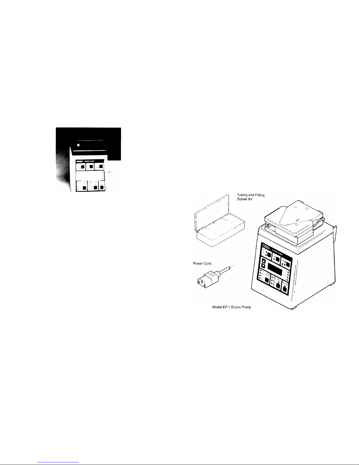
ed with the Model EP- I Econo Pump are illustrated in Figure 3.l. Check
off all parts against the supplied packing list.
Your Model EP- l Econo Pump was carefully tested at the factory and was
shipped in good working order. If any part is missing or damaged, contact BioRad Laboratories immediately. Refer to Figure 3.1 for the proper identification designation of any missing or damaged part(s).
Also includes: Instruction Manual
Fig. 3.1. Parts supplied with the Model EP-1 Econo Pump.
3
2
Page 5
3.2 Voltage Conversion
Warning: The Model EP- I Econo Pump is shipped in its 120 V or 220 V
version. To operate at other voltages, refer to the procedure below. Failure
to follow this procedure may result in damage to the unit and invalidation of the warranty.
Prior to connecting the power cord to the power entry module and wall
outlet, verify that the voltage indicated on the power entry module matches
your line voltage. If it does not, use the following procedure to make the
conversion. Refer to Figure 3.2.
1.Disconnect the power cord from the unit.
2.Remove the fuse drawer with a small-blade screwdriver or similar tool.
3.Pull the fuse holder out of the fuse drawer and, if necessary, replace the
fuses with ones having the correct current rating. Use 0.50 A fuses for 100
V and 120 V operation; 0.25 A fuses for 220 V and 240 V operation.
Rotate the voltage selector through the window in the fuse drawer until
the proper voltage shows.
4.Reinsert the fuse drawer into the power entry module, with the locking
tab to the left. The voltage indicator will read right-side-up if the drawer is oriented correctly. Press gently until it snaps into place.
5.Insert the power cord plug into the power entry module. Plug the powe
cord into a properly grounded
outlet.
Fig. 3.2. Voltage conversion.
Section 4
Physical Description and Control Features
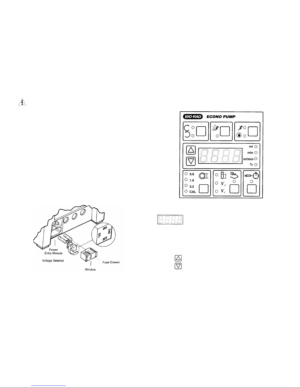
4.1 Front Panel Functions
Fig. 4.1. Front panel controls.
Display
Function
Arrow Keys
The four-character display will show
various parameters during programming and operation of the Econo
Pump, Econo System, and Automated
Econo System. The indicator lights
l
ocated immediately to the right of the
display indicate the units displayed:
ml, minutes, ml/minute, or percent.
These keys are used for setting system
parameters when program ming the
system, and for selecting which parameter to display when running the
system.
4
5
LED Display
Page 6

Run/Stop Key
Purge Key
Direction Key
Tubing Calibration Key
Fraction Collector Key
These lights indicate the units for the
value displayed on the LED display
located to the left. A flashing light
indicates that a value can be set using
the Arrow keys.
This key is used to start or stop the
pump. It also has secondary functions such as holding or aborting a
method.
This key is used to prime and purge
tubing lines without disturbing the primary speed setting of the pump. When
Purge is pressed, the pump will run at
maximum speed (25 rpm). The purge
key will not operate during a gradient
or fraction collection method.
This key changes the direction of
pump head rotation. The Econo Pump
must be stopped before the direction
can be changed.
This key is used to select pre-programmed calibration settings for three
tubing sizes, or allows user calibration
for increased flow rate accuracy or
non-standard tubing sizes. The pump
must be stopped for this key to operate.
This key is used to set fraction size,
void volume (to move a diverter valve
to "collect" or "waste" positions), and
total run volume. The total run volume (V) may be used to program the
pump to automatically shut off after a
given volume has been delivered.
4.2 Rear Panel Functions
Fig. 4.2. Rear panel sockets.
Program Run Key
Note: When entering values for tubing calibration or fraction collection
procedures, only the flashing keys are active.
Display
Power Entry Module
Fraction Collector
Output
Diverter Valve Output
This key is used to control a programmed gradient or fraction collection method.
When the indicator light
is
flashing, pressing this key starts the
method.
When the indicator light is
lit,
pressing this key will interrupt the
program, which can be continued by
pressing again.
When the LED displays "FAIL", (indicating a brief
power outage has occurred), pressing
this key continues the program.
Function
Grounded 3-pin receptacle for the
power cord. Also contained within is a
four-position (100 V/120 V/220 V/
240 V) line voltage selector. See
Section 3.2.
This 8-pin connector sends an
advance signal to the Model 2110
Fraction Collector via Econo System
Cable # l.
This 8-pin outlet sends a signal to the
Model SV-3 diverter valve, to divert
flow between collection devices.
Indicator Lights
6 7
Page 7

5.2 Installation of Precut Bio-Rad Tubing
4.3 Pump Base Features
The base of the Model EP-1 Econo Pump contains a 40-pin connector for
connection to the Model ES-1 Econo System Controller via a ribbon cable
located on the Model ES-1 Econo System Controller. When connected, the
two provide added features such as gradient proportioning and mixing, peak
detection, and control of a waste/collect diverter valve. See Section 6 for
details.
Section 5
Tubing Selection and installation
5.1 Tubing Selection
The Model EP-1 Econo Pump may be used with most flexible tubing
having an inner diameter less than or equal to 3.2 mm (l/8"), and a wall
thickness of 1.0 mm or less, including silicone, Tygon, and PharMed. Silicone
tubing, the most inert of the three, is suitable for aqueous and polar solutions. Tygon is suitable for most aqueous solutions. It will generally have
the shortest lifetime of the three. PharMed is the longest lasting of the three
,
and will provide the most consistent flow rate over time. Table 5.l shows
approximate flow rate ranges with different tubing sizes. Flow rates above 20
ml/min may be obtained by plumbing two channels of 3.2 mm tubing through
the pump and joining them at the output.
Table 5.1. Approximate Flow Rate Ranges
Fig. 5.1. Tubing installation.
l.
Referring to Figure 5.l, pull the platen cam lever away from the pump
head to unlock the platen and slide the platen away from the pump head
frame assembly, exposing the rollers.
2.
Slip a lock-ring onto one end of the tubing. See below for the size and
color of each lock-ring. Insert a barbed female luer-fitting into the same
end until the tubing reaches the flange of the fitting. Clamp the luer-fit
ting into place by sliding the lock-ring along the tubing over the barbed
fitting (see Figure 5.2). Repeat on the other end of tubing.
Note: Use of lock-rings is required only when operating at pressures
above 10 psi.
Lock-Ring Color
Tubing ID
Red
0.8 mm (1/32")
Orange
1.6 mm (1/16")
Yellow
3.2 mm (1/8")
This 8-pin connector is for communication with the Model EM- l Econo
UV Monitor.
Auxiliary Output
8
9
Page 8

Fig. 5.2. Attachment of tubing fittings.
3.Insert one end of the tubing into the tubing retaining bracket of the pump
head. Lightly pull the tubing around the rollers to remove slack. Attach
the other end of tubing into the tubing retaining bracket on the opposite
side of the pump head.
4.Slide the platen back into the pump head frame assembly until it rests up
against the tubing. Press the cam lever in toward the pump head, locki
ng the platen up against the tubing and rollers. Note that the platen can
be inserted with the cam lever on the left or the right.
5.
Proper adjustment of platen pressure increases flow stability, minimizes
flow pulsation, and prolongs the life of the tubing.
6.Attach system tubing to the pump tubing using Bio-Rad's luer-type fittings or other suitable connectors. Lock-rings are not necessary for system tubing.
5.3 Installation of Uncut Tubing
Tubing length and the amount of tubing prestretch have a significant
effect on both flow rate calibration and reproducibility of flow. The PharMed
tubing supplied with the Model EP-1 Econo Pump has been cut to a prede
termined length to accommodate tubing prestretch. When using any tubing
that is not properly sized, the tubing must be cut to accommodate prestretch.
Tubing should be cut as follows:
Note: Overtightening the platen adjustment screw will reduce flow rate
and shorten tubing life. If the platen is too loose, flow rate will decrease
as backpressure increases.
Tubing
Length
Tygon, PharMed
1
79 mm +/- 1.5 (7.04" +/- 0.05)
Silicone
171 mm +/- 1.5 (6.75" +/- 0.05)
Install tubing onto the pump head as described in Section 5.2.
Warning: If using tubing other than the type supplied by Bio-Rad, make
sure the wall thickness is not greater than 1.0 mm. Using tubing with a
greater wall thickness can damage the pump and void your warranty.
a.Loosen the platen adjustment screw, located on the front of the plat-
en, counterclockwise until the stop is reached.
Section 6
Operation
b.
Cut tubing to proper length and install fittings and lock-rings as
described in Section 5.2. Install tubing in pump as described in Figure
5.l. Start the pump and set flow rate to the value you expect to use for
your application.
c.
Turn adjustment screw clockwise just until uniform flow is achieved.
This will be evident by observing the uniform motion of bubbles in the
line (if any) or a motion-free inlet line when operating with the expected backpressure.
Typically, one piece of silicone tubing will perform well with two turns
clockwise from stop. One piece of Tygon or PharMed tubing will perform
well between three and four turns clockwise from stop. When using two
pieces of tubing, approximately 50% more turn clockwise from stop will
be required. A clockwise stop will occur at eight turns clockwise.
6.1 Start-Up Procedure
1.Plug the Model EP-1 Econo Pump into an appropriate
grounded power source. Turn on the power switch on
the bottom of the unit. The pump will power up in the
Stop mode, with the LED display showing 0% of maxi
mum speed.
2.
With tubing in place, set the desired pump speed by
pressing the Arrow keys.
3.
Press the Run/Stop key to initiate flow. Press once more
to stop the flow. Flow rate will be displayed in percent
of maximum speed. Change the flow to the desired
speed while the pump is running by pressing the Arrow
1
0
11
Page 9

keys.
6.3 Flow Rate Calibration
4.To change the direction of flow, stop the pump by pressi
ng the Run/Stop key. Press the Direction key to choose
the new direction. Restart by pressing the Run/Stop key.
5.To purge the tubing, press the Purge key. The pump will
run at 100% maximum speed. When the tubing is
primed, press the Purge key again to stop the purge
function and return to the Run mode, or press the
Run/Stop key to turn the pump off.
An uncalibrated Model EP- I Econo Pump will display pump speed as percent of maximum rpm. The user may also choose to select one of three tubing sizes for which calibration has been programmed at the factory. The
Model EP-1 Econo Pump also features a user calibration mode, which is
used when improved flow rate accuracy is desired, or when using non-standard size tubing. The pump must be calibrated using one of the methods
described above before a fraction collection program may be entered.
Flow Rate Calibration with Pre-Selected Tubing Sizes (0.8, 1.6,
and 3.2 mm ID)
6.2 Verification of Econo System Software Version
The Model ES-1 Econo System Controller and Model EP-1 Econo Pump
should already be set up.
The Model EP-1 Econo Pump
must
have software version 2.01 or
higher to control the Model EV-1 Econo Buffer Selector.
If you do not have a Model EV-1 Econo Buffer Selector, continue with
Section 6.3. Otherwise check the software version of your system:
Simultaneously press and hold the Direction Key and the "down"
Arrow key on the front panel of the Model EP-1 Econo Pump. The
four digit LED display on the front panel of the Pump should dis-
play: "v2.01" or higher.
If your pump displays a number lower than 2.01,and you will be
using the Model EV-1 Econo Buffer Selector, your pump software
should be upgraded. Contact your local Bio-Rad representative for
details on how to upgrade software.
If your pump currently features software version 2.01 or higher
,
insure that all connections between the Model EP-1 Econo Pump,
Model ES-1 Econo System Controller, (and Model EV-1 Econo
Buffer Selector, if used) have been completed and the system power
is on.
1
2
User Calibration Procedure
1.With the pump in Stop mode, install tubing as described
in Section 5.2.
2.Press the key in the lower left-front of the pump panel
corresponding to the pump calibration feature, and continue pressing until the indicator light corresponding to
either 0.8, l.6, or 3.2 mm ID tubing is lit.
3.The LED display reads ml/min for any of these pre-pro-
grammed tubing settings. If improved flow rate accuracy
is desired, see User Calibration Procedure below.
4.The pump is now automatically calibrated for the specific tubing size. Press the Run/Stop key to start flow.
Increase or decrease the pump speed with the Arrow
keys.
1.
Install tubing as described in Section 5.2. Connect pump
inlet to a container of water or buffer. Connect a length
of tubing to the pump outlet.
2.Run pump to purge air from tubing, then stop pump.
Place the end of the outlet tubing in an empty graduated
cylinder.
3.Press Calibration key until "CAL" is displayed. Press the
Run/Stop key. Pump will run for 5 minutes at 25% of
maximum speed, and the display will count down time.
13
Page 10

4.
When pump stops, read the volume of fluid on the graduated cylinder. Using the Arrow keys, enter this amount
on the display. Alternatively, when a suitable volume of
liquid has been collected, pressing Run/Stop will turn
off the timer and stop the pump. Enter volume collected
as described.
5.
When the value on the display matches the volume collected in the graduated cylinder, press Calibration. The
"CAL" indicator light will glow steadily, indicating that
the pump is calibrated. DO NOT select a tubing size at
this point, even if you are using one of the standard
sizes. The pump will "remember" the calibration key
even if it is switched off or disconnected from the power
line.
6.
Set desired flow rate using arrow keys.
Note: Flow rate depends on condition of tubing, platen
adjustment, and back pressure. For maximum flow rate
accuracy it may be necessary to recalibrate as the tubing
ages, when the tubing is replaced, if the platen is read-
justed, or if back pressure changes significantly.
6.4 Simple Time-Based Collection with the Model
2110 Fraction Collector
In addition to its features as a stand-alone pump, the Model EP-1 Econo
Pump is capable of controlling the Model 2110 Fraction Collector as well as
other fraction collectors (for operation with collectors other than the Model
2110 Fraction Collector, see Appendix B). The pump must be calibrated in
order to run a fraction collection scheme. See Section 5.3 for calibration.
Use Econo System Cable #l to connect the I/O
socket on the rear panel of
the fraction collector to the 8-pin connector on the rear of the Model EP-1
Econo Pump (see Figure 4.2).
1.
Press the Fraction Collector key on the pump front panel
to enter the fraction collector Edit mode. Note that the
fraction size and ml indicator lights are flashing,
prompting entry of fraction size. Enter the fraction size
in 0.l ml increments using the Arrow keys. After fraction size is selected, press the Fraction Collector key
once more to confirm the fraction size.
14
2.
3.
*Note: The Econo Pump will automatically shut off upon
reaching the total run volume (Vt).
4.
5.
6.
Enter a void volume (V) in I ml increments using the
Arrow keys. This feature allows the user to begin collecting fractions only after a pre-set volume of liquid
(i.e., the void volume) has passed through the column.
Press the Fraction Collector key to confirm this value. If
a void volume is not desired, enter 0.
Note: The optional Model SV-3 Diverter Valve (catalog
number 731-8235) is required to use the void volume
feature of the Model EP-1 Econo Pump.
Select the total run volume (V) in 1 ml increments using
the Arrow keys.* If zero is entered and confirmed, the
fraction collection scheme is disabled. To resume data
entry, see Step 1 above. All values previously entered
remain in the memory until other values are entered to
replace them.
After selecting a V
value, press the flashing Fraction
Collection key to enter the value. The flashing LED display shows the estimated number of fractions to be collected.
Press the flashing Fraction Collection key once more to
enable the fraction collector. To actuate the fraction collector, press the Program Run key after starting the
pump. (The fraction collector can be programmed with
the pump running or stopped.) After the fraction collection program is initiated, the LED display shows the
progression of the fraction collection scheme in minutes,
to the nearest tenth of a minute.
While a program is running, the user can use the Arrow
keys to display the ml of output, the progression of the
collection in min, the flow rate in ml/min, or the percent
of total run-time. If the Econo Pump is connected to the
Econo System Controller and the Gradient Former is
enabled, % buffer B can also be viewed while a program
is running.
15
Page 11

9.When the fraction collection program is complete, the
pump stops and the display reads "END." Press any key
to return to the ready mode.
Notes on Fraction Collection:
1.After a fraction collection program has begun, the pump cannot be turned
off without terminating the fraction collection program.
2.During the V, period of the fraction collection scheme (as indicated by
the V, indicator light), the fraction collector is not active. To collect fractions during this void volume period, cancel V, by pressing the Fraction
Collector key. The fraction collector will start, with the LED display
indicating the time-progression of the collection scheme.
3.When the fraction collector is disabled by pressing the Fraction Collector
key, the fraction collector carousel will advance one tube.
4.When the fraction collector indicator light on the pump is lit, the Model
2110 Fraction Collector will be put into remote mode. Only the manual
advance keys will be active, and the Model 2110 display reads ---.
5.The fraction collection control feature of the Model EP-1 Econo Pump
can be used to turn off the pump even if a fraction collector is not connected. Simply enter 0 for fraction size. After confirming the V value
entered (the V light will be lit solid), start the pump, if not already running; then press the flashing Program Run key. The LED display will
show time elapsed. The pump will stop automatically when the total run
volume has been delivered.
1
6
7.
To abort the fraction collection scheme at any time duri
ng the program, press the Run/Stop key twice. The
pump will stop, and the LED display will read OFF,
i
ndicating abortion of the fraction collection program.
Note: When a program is aborted, it can only be restarted from the beginning.
8.To place a collection program that has begun on Hold,
press the lit Program Run key once. The pump will stop
and the program will be held. To resume the collection
program, press once again. Pressing the Run/Stop key
while the program is on hold will abort the fraction collection scheme.
Use of the Diverter Valve
The optional Model SV-3 diverter valve (catalog number 731-8235) provides a means to divert the eluant stream from a fraction collector to a waste
receptacle or other collection device during a fraction collection program. It
fits conveniently to the Econo System Rack. If the void volume function
(V
o
) of the collection scheme is enabled with the diverter valve in place, the
eluant stream will be diverted away from the fraction collector during that period.
When that period is over, the eluant stream will be diverted to the frac-
tion collector.
Whenever the diverter valve changes from waste to collect, or
vice versa, an event mark is generated. This will appear as a deflection on the
chart recorder. For connection of the diverter valve, see Figure 6.l.
Fig. 6.1. Connection of the Model SV-3 Diverter Valve.
17
Page 12

Section 7
Cleaning and Maintenance
Section 8
Troubleshooting
18 19
The Model EP-1 Econo Pump requires very little maintenance to assure
reliable operation. The procedures outlined below will insure maximum
pump life:
•Check tubing regularly for signs of cracking and wear. If any exist,
replace the tubing.
•
For optimal tubing life, use a slow to medium pump speed. To increase
throughput, increase tubing size to obtain the desired output.
•When not in use, tubing should be removed from the pump to prevent
deformation of the tubing. Remove the platen and relax the tubing by
unhooking one end of the tubing from the tubing bracket.
•To prevent the formation of precipitates around the pump head and on the
membrane key panel, promptly remove any spills. Clean with deionized
water.
Problem
Possible Cause Solution
Pump displays
Power surge or
l.
Turn the power switch off.
"OUT"
brownout
2.
Press and hold down the
(up arrow) key and the (CAL)
key simultaneously while turning
the power switch on. This will
reset the pump. If the pump was
previously calibrated you will
have to recalibrate it.
Pump displays
Power outage
If you wish to continue a run in
"FAIL"
progress, press (program run)
key. Otherwise, press the
(run/stop) key.
Pump will not run
No power
Verify that powercord is plugged
(no LEDs lit)
in and the power switch is turned
on.
Fuses
Check that proper fuses are
installed and intact.
Problem
Possible Cause
Solution
Insure that the calibration indicatorlight is not flashing. For pump
to run, this light must either be
off or steadily lit.
Liquid remains
Platen not adjusted
Platen too loose. Turn platen
stationary in tubing
screw clockwise just until liquid
begins moving within tubing.
Clogged tubing, Check tubing, fittings, and valves
valves, or fittings
for obstructions.
Damaged tubing
Check pump tubing for damage.
Replace damaged tubing.
Flow rate not
Pump tubing
Replace tubing.
consistent
damaged or worn out
Platen adjustment
Adjust platen.
incorrect
Wrong tubing size Re-select tubing size on front
selected
panel of pump.
Large change in
Re-calibrate flow.
back pressure or
fluid viscosity
Restriction on inlet
Remedy
side
Excessive tubing
Platen too tight
Turn platen adjustment screw
wear
clockwise to stop flow, then
clockwise until flow starts.
Cannot calibrate
Pump must be Insure that pump is stopped.
pump
stopped in order to
calibrate pump
Error message
Contact Bio-Rad Instrument
displayed upon
Service Department
powering up (ER ##)
OIL
Page 13

Appendix A
2
0
Appendix B
Operation of the Model EP-1 Econo Pump When
Connected to Other Instruments
The Model EP-1 Econo Pump provides a variety of output signals which
can be used to control the operation of non Bio-Rad fraction collectors, or to
communicate with non Bio-Rad UV monitors and recording devices.
Communication is accomplished through two standard 8-pin mini-DIN sockets on the rear panel of the pump. The third socket is for the operation of
the Model SV-3 Diverter Valve (see Figure 4.2). Bio-Rad offers an accessory breakout cable (Econo System cable #7), which has an 8-pin mini-DIN connector at one end and loose wires on the other, for connection to non Econo
System instruments. Output signals are TTL compatible. To use these signals,
you must insure that the circuit external to the Model EP-1 Econo Pump
does not draw more than 15 milliamperes of current. The following table
describes the two rear panel mini-DIN connector pinouts.
Table B. Rear Panel Pinouts
21
Technical Specifications
Number of channels
2
Flow rate range (per channel)
0.1-20 ml/min (depending on tubi
ng diameter)
Pump head speed
25 rpm maximum
Tubing diameter
0.4 mm ID to 3.2 mm ID
Speed adjustment
1
Speed stability
1
% of full scale
Maximum counterpressure
30 psi (2 kg/cm2 or bars)
Motor
DC speed controlled, 55 watts
Line voltage
90-132 VAC
180-265 VAC
47-63 Hz
Dimensions
143 x 202 x 222 mm
(
W x D x H) with pumphead
Weight
3.3 kg
Operating temperature
4 to 40 °C
Material of construction
polypropylene and other solvent
resistant plastics
Pinout
Signal Type
Pinout
Signal Type
Shield Shield
1
Fraction Advance
1
Start/Enable
(low-going output)
(output)
2
No Contact
2
No Contact
3
No Contact
3
Mark A (output)
4
No Contact 4 No Contact
5
Fraction Advance
5 No Contact
(high-going output)
6
No Contact 6
Pen (output)
7
Ground
7
Ground
8
Fraction Advanced Marks to
8
Mark B (output)
Recorder (low-going input)
Page 14

Appendix C
Ordering Information
Catalog
Number
Product Description
Model EP-1
Econo Pump
731-8140Model EP-1 Econo Pump, 110 V (USA power cord), with
tubing set and starter fittings kit
731-8142
Model EP-1 Econo Pump, 220 V (no power cord), with
tubing set and starter fittings kit
731-8145Model EP-1 Pumphead Assembly
731-8235
Model SV-3 Diverter Valve
Tubing and Accessories
731-8210Silicone Tubing, 0.8 mm ID, 0.8 mm wall, 10 m
731-8211Silicone Tubing, 1.6 mm ID, 0.8 mm wall, 10 m
731-8212Silicone Tubing, 3.2 mm ID, 0.8 mm wall, 10 m
731-8214
Tygon®Tubing, 0.8 mm ID, 0.8 mm wall, 10 m
731-8215Tygon Tubing, 1.6 mm ID, 0.8 mm wall, 10 m
731-8207PharMed Tubing, 0.8 mm ID, 1.0 mm wall, 10 m
731-8208PharMed Tubing, 1.6 mm ID, 1.0 mm wall, 10 m
731-8219PharMed Tubing, 3.2 mm ID, 1.0 mm wall, 10 m
731-8240Silicone Tubing Kit, 0.8 mm ID, 20 precut lengths and 4
sets of fittings
731-8241Silicone Tubing Kit, 1.6 mm ID, 20 precut lengths and 4
sets of fittings
731-8242
Silicone Tubing Kit, 3.2 mm ID, 20 precut lengths and 4
sets of fittings
731-8247PharMed Tubing Kit, 0.8 mm ID, 20 precut lengths and 4
sets of fittings
731-8248PharMed Tubing Kit, 1.6 mm ID, 20 precut lengths and 4
sets of fittings
731-8249
PharMed Tubing Kit, 3.2 mm ID, 20 precut lengths and 4
sets of fittings
22
Catalog
Number
Product
Descri
ption
731-8228Low Pressure Fittings Kit, includes over 250 male and
female luer connectors, 2- and 3-way stopcocks, and tubi
ng connectors
Cables
731-8261Econo System Cable 1, 8-pin mini-DIN to DB-9 connector.
For connection of Model 2110 Econo Fraction Collector to
the Econo Pump, Econo UV Monitor, or Econo System
Controller
731-8262Econo System Cable 2, 8-pin mini-DIN to 8-pin standard
DIN. For connection of Econo Recorders to the Econo UV
Monitor, Econo Pump, Econo Gradient Monitor, or Econo
System Controller
731-8263Econo System Cable 3, 8-pin mini-DIN to 8-pin mini DIN.
Connects the Econo Pump to the Econo UV Monitor in the
absence of the System Controller
731-8264Econo System Cable 4, 8-pin mini-DIN to banana cable.
To connect Econo UV Monitor to most non-Bio-Rad chart
recorders
731-8265Econo System Cable 5, DB-9 connector to bare wires. For
connection of Model 2110 Econo Fraction Collector to nonEcono System components
731-8266Econo System Cable 6, 8-pin standard DIN to bare wires.
To connect Econo Recorder to non-Econo System detectors
731-8267Econo System Cable 7, 8-pin mini-DIN to bare wires. To
connect Econo Pump, Econo UV Monitor, or Econo System
Controller to non-Econo System components
731-8268Econo System Cable 8, 8-pin standard DIN to DB-9 con-
nector. For connection of Econo Recorders to Econo
Fraction Collector
731-8269
Econo System Cable 9, 8-pin mini-DIN to Pharmacia Frac-
100. For connection of Pharmacia Frac-100 fraction collec-
tor to the Econo System
731-8281Econo System Cable 10, 8-pin mini-DIN to 11-pin connec-
tor . For connection of the Model EV-1 Econo Buffer
Selector to the Econo System Controller.
PharMed and Tygon are the registered trademarks of the Norton Company.
23
 Loading...