


BERTAZZONI
INSTALLATION AND USER MANUAL
BUILT-IN GAS HOBS
MODEL P93V (METAL)
MODEL P94GV (GLASS)
INSTRUCTIONS D’INSTALLATION ET D’UTILISATION
PLAQUES DE CUISSON ENCASTRABLES AU GAZ
TYPE P93V (MÉTAL)
TYPE P94GV (VERRE)
EN
FR
3100419
WWW.BERTAZZONI.COM

/ Contents
CONTENTS
EN
INTRODUCTION AND WARNINGS _________________________________________________
MANUFACTURER LIABILITY ____________________________________________________
ENVIRONMENTAL PROTECTION _________________________________________________
GENERAL SAFETY INSTRUCTIONS_______________________________________________
USAGE INSTRUCTIONS ________________________________________________________
APPLIANCE DATA PLATE ______________________________________________________
PLASTIC PACKAGING _________________________________________________________
TECHNICAL INSTALLATION INSTRUCTIONS_________________________________________
HOB INSTALLATION __________________________________________________________
IMPORTANT INFORMATION
INSTALLING THE HOB ABOVE AN OVEN _________________________________________
INSTALLING THE HOB ABOVE A CUPBOARD OR DRAWERS _________________________
HOB FASTENING________________________________________________________________
ROOM VENTILATION ___________________________________________________________
LOCATION AND VENTILATION____________________________________________________
CONNECTING THE APPLIANCE TO THE GAS SUPPLY_______________________________
PRECAUTIONS WHEN USING THE PRODUCT WITH LPG (BUTANE/PROPANE)
GAS CONVERSION ____________________________________________________________
ELECTRICAL CONNECTION ______________________________________________________
MAINTENANCE ________________________________________________________________
REPLACING COMPONENTS ____________________________________________________
______________________________________________________
___________
4
4
4
5
5
5
5
6
6
6
7
7
8
8
9
9
10
11
12
12
12
HOB DESCRIPTION _____________________________________________________________
USING THE APPLIANCE _________________________________________________________
BURNERS AND GRATES ________________________________________________________
USING THE BURNERS _________________________________________________________
SAFETY SYSTEM ______________________________________________________________
MANUAL IGNITION _____________________________________________________________
ACCESSORIES ________________________________________________________________
CLEANING THE APPLIANCE_____________________________________________________
TROUBLESHOOTING___________________________________________________________
13
14
14
14
15
15
15
15
16
2
/ From the desk of our president
FROM THE DESK OF OUR PRESIDENT
Dear new owner of a Bertazzoni appliance,
I want to thank you for choosing one of our beautiful products for your home.
My family started manufacturing kitchen appliances in Italy in 1882, building a
reputation for quality of engineering and passion for good food.
EN
Today, our products stand out because of their unique blend of authentic Italian
design and superior appliance technology. It is our mission to make products
that function perfectly and bring joy to their owners.
By making beautiful products we respond to our customers’ fl air for good design.
By making them versatile and easy-to-use, cooking with Bertazzoni becomes a
real pleasure.
This manual will help you learn to use and care for your Bertazzoni appliance in
the safest and most eff ective way, so that it can give you the highest satisfaction
for years to come.
Enjoy!
Paolo Bertazzoni
President
3
/ Introduction
INTRODUCTION
EN
READ THESE INSTRUCTIONS CAREFULLY
BEFORE INSTALLING AND USING THE
APPLIANCE.
These instructions are valid only for the countries
whose identifying symbols are shown on the
appliance label.
The manufacturer shall not be held liable for
property damage or personal injury resulting
from incorrect installation or improper use of the
appliance.
The manufacturer shall also not be held liable for
any imprecisions due to printing or transcription
errors in this booklet.
The appearance of the fi gures included herein is
only for guidance.
The manufacturer reserves the right to make
modifi cations to its products when it considers this
necessary or benefi cial, however the essential
safety and performance characters shall not be
aff ected.
THIS APPLIANCE IS DESIGNED FOR NONPROFESSIONAL, DOMESTIC USE.
This user manual is an integral part of the appliance
and must therefore be kept in its entirety in a place
accessible to the user for the entire lifetime of the
appliance.
Read this manual before using the appliance.
MANUFACTURER LIABILITY
The manufacturer shall bear no liability for
property damage or personal injury due to:
• Use of the appliance other than that specifi ed
• Failure to comply with the instructions in the
user manual
• Tampering with/unauthorised modifi cations to
any part of the appliance
• The use of non-original spare parts.
• This appliance is intended for cooking food in
the home environment. Any other use shall be
considered improper.
• The appliance is not designed to operate
with external timers or with remote-control
systems.
ENVIRONMENTAL PROTECTION
Please think of the environment
when disposing of the packaging.
This appliance is marked in accordance with
European Community Directive 2012/19/EU
on waste electrical and electronic equipment
(WEEE).
This directive defi nes the standards for the
collection and recycling of waste electrical and
electronic equipment applicable throughout the
European Union.
The packaging of this appliance is composed of
the elements strictly necessary to ensure suffi cient
protection during transport. The packaging
materials are completely recyclable, thus reducing
their environmental impact. Please help to protect
the environment by taking the following tips into
consideration:
• Sort the packaging materials for recycling
• Render the old appliance unusable before
taking it to the collection facility Ask the
competent local authorities for details of the
nearest recycling centre you can take the old
appliance to.
• Do not dispose of used oil down the drain.
Keep it in a closed container and take it to a
recycling centre; if this is not possible, dispose
of it in mixed waste (in this manner it will be
disposed of at a monitored facility – although
this is not the best solution, it at least prevents
contamination of the sewage/water systems).
WARNING: The
a declaration, under the manufacturer’s full
responsibility, that the product complies with
all European health, safety and environmental
requirements laid out in the legislation covering
this product type.
4
marking on this product is

INTRODUCTION
/ Introduction
GENERAL SAFETY INSTRUCTIONS
• During use, the appliance and its accessible
parts become very hot.
• Never touch the heating elements during use.
• Keep children under the age of eight at a
safe distance unless they are constantly
supervised.
• Children must not play with the appliance.
• This appliance may only be used by children
over the age of eight, and by people with
reduced physical, sensory or mental capacity,
or lacking in experience in the use of electrical
appliances, provided that they are supervised
or instructed by adults who are responsible for
their safety.
• Never rest metal objects on the appliance
during use, as these could become red hot.
• Switch off the appliance after use.
• Never try to put out a fi re or fl ames with water:
Turn off the appliance and smother the fl ames
with a fi re blanket or other appropriate cover.
• Cleaning and maintenance must not be carried
out by children without adequate supervision.
• Ensure that hot surfaces are allowed to cool
before proceeding to clean the appliance.
• Have installation and servicing carried out
by qualifi ed personnel in compliance with
applicable standards and legislation. Do not
try to repair the appliance yourself or without
the assistance of a qualifi ed technician.
• Do not modify this appliance.
• Do not insert anything in the slots.
• Do not obstruct ventilation openings and heat
dispersal slots.
• If the power supply cable is damaged, contact
technical support immediately and they will
arrange for it to be replaced.
• Do not use abrasive or corrosive detergents
(e.g. scouring powders, stain removers and
metallic sponges) on glass parts.
• Do not sit on the appliance.
• Do not use steam jets to clean the appliance.
• Never leave objects on the cooking surface.
• Do not use the appliance as a space heater
for any reason.
• In the event of breakage or cracking of the
glass, shut off all burners immediately and
isolate the hob's gas and electricity supplies.
Contact technical support.
• Sudden and extreme changes in temperature
can cause the glass to break – never pour
cold liquids onto the hob.
• Damaged or unsuitably sized cookware which
overhangs the edges of the hob or is poorly
positioned can cause serious injury.
• Using the hob generates heat, moisture and
combustion products – keep the area well
ventilated during operation.
INSTRUCTIONS FOR USE
• Use fl at-based cookware.
• Position pans before lighting the burners.
• Never leave the hob when cooking foods with
oil and grease, as they can fl ash over and
ignite easily.
• Do not use aerosols in the vicinity of this
appliance while it is in use.
• Adjust the fl ame so that it does not protrude
beyond the edge of the pan base, as this could
damage the handles.
• Do not place pans directly on the burners.
• Ensure that the pan is centred over the burner.
APPLIANCE DATA PLATE
The data plate bears the technical data, serial
number and brand name of the appliance. The
appliance data plate is located on the lower
casing, and must not be removed at any time. A
copy is provided in this manual for reference.
PLASTIC PACKAGING
Danger of suff ocation
• Do not leave the packaging or any part thereof
unattended.
• Do not let children play with the plastic bags.
EN
5
/ Installation
T
S
TECHNICAL INSTALLATION INSTRUCTIONS
ECHNICAL INSTALLATION INSTRUCTION
EN
The installation, adjustments, transformations and
maintenance listed in this section must only be
performed by qualifi ed technicians (in accordance
with applicable legislation). Incorrect installation
can cause property damage and injury to people
or pets; the manufacturer shall not be held liable
in this event. The appliance’s automatic regulation
or safety devices may only be modifi ed by the
manufacturer or a duly authorised supplier during
the appliance’s lifetime.
Ensure all necessary PPE is used when
carrying out the installation
INSTALLING THE HOB
Ensure that the hob is fully present and undamaged
after removing all loose parts from their inner and
outer packaging. In the event of any uncertainty,
do not use the appliance and contact technical
support.
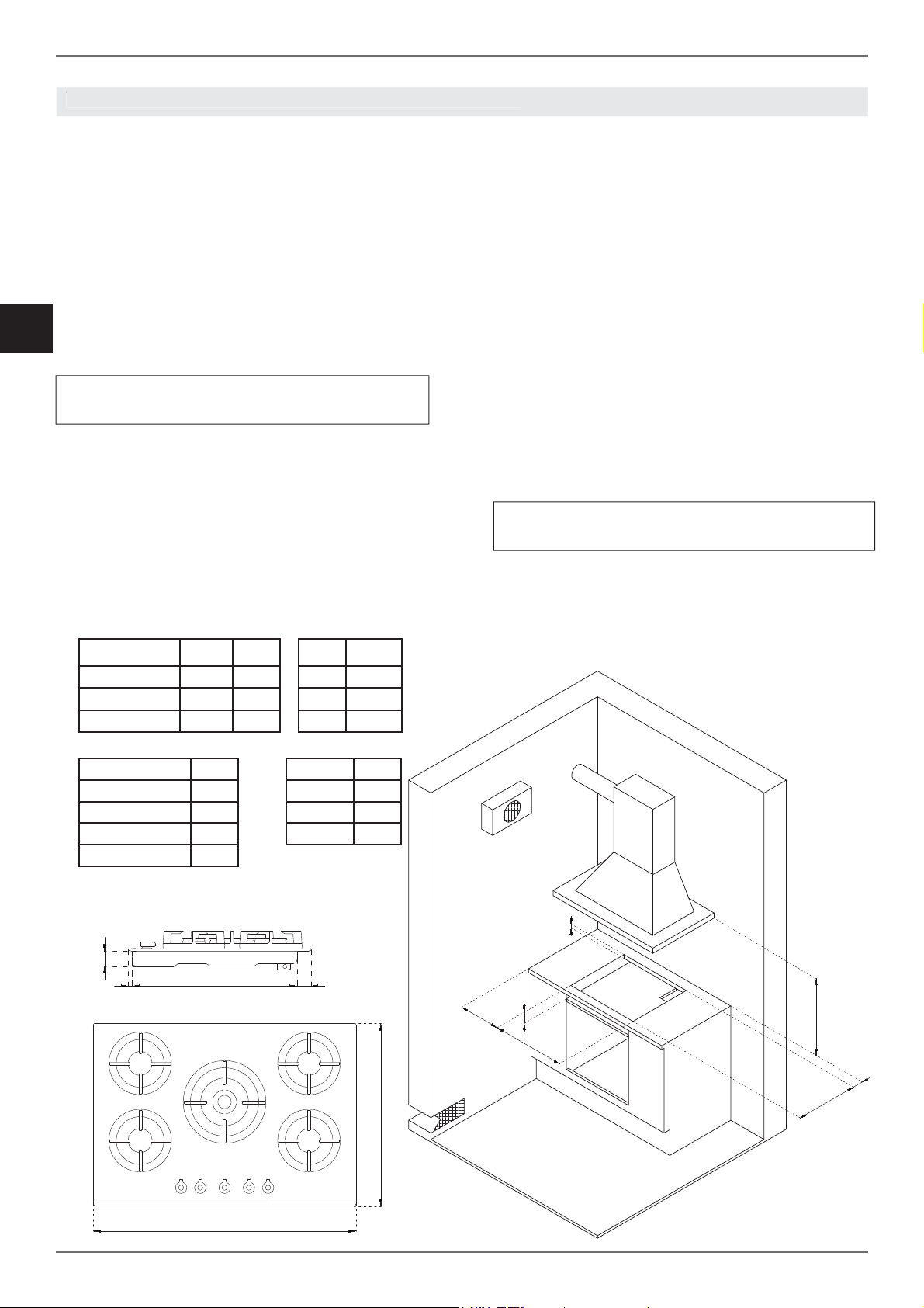
Make a cut-out in the worktop (see fi gure) in
accordance with the appliance dimensions given
in the table.
IMPORTANT INFORMATION
The hob may be installed between kitchen cabinets
or between a cabinet and a (masonry) wall. The
rear wall and surrounding surfaces must be able to
withstand temperatures of up to 90°C. To prevent
peeling of the melamine laminate typically used
on kitchen carcases, the glue bonding it must be
able to withstand temperatures of at least 150°C.
Installation of the appliance must be performed
in accordance with the provisions of applicable
legislation.
This domestic appliance is not connected to an
extraction device for combustion products. It
must therefore be connected in accordance with
the above-mentioned installation rules. Particular
attention must be paid to room ventilation
requirements.
The worktop must be able to withstand a maximum
temperature of 90°C (120°C for the 75cm version)
A (cm) B(cm) H(cm) L(cm)
60cm hob 56 48 60,5 52,5
75cm hob 56 48 75,5 52,5
90cm hob 85 48 89,3 52,5
C min (cm) 8,5 M (cm) 4,4
D min (cm) 3 N (cm) 1,1
E min (cm) 18 P (cm) 47,4
F min (cm) 70 Q (cm) 4
G min (cm) 8,5
M
NPQ
'
*
(
$
L
)
&
%
H
6
TECHNICAL INSTALLATION INSTRUCTIONS
T
S
ECHNICAL INSTALLATION INSTRUCTION
/ Installation
INSTALLING THE HOB ABOVE AN OVEN
The clearance between the hob and the
kitchen furniture or other installed appliances
must be enough to ensure suffi cient ventilation
and air discharge.
If installed above an oven, space must be
left between the bottom of the hob and the
top of the product installed below to allow for
ventilation of the entire compartment (see
fi gure).
The oven must be equipped with a cooling
device. The manufacturer shall bear no
liability in the event of the hob being installed
in combination with an oven from another
manufacturer.
40
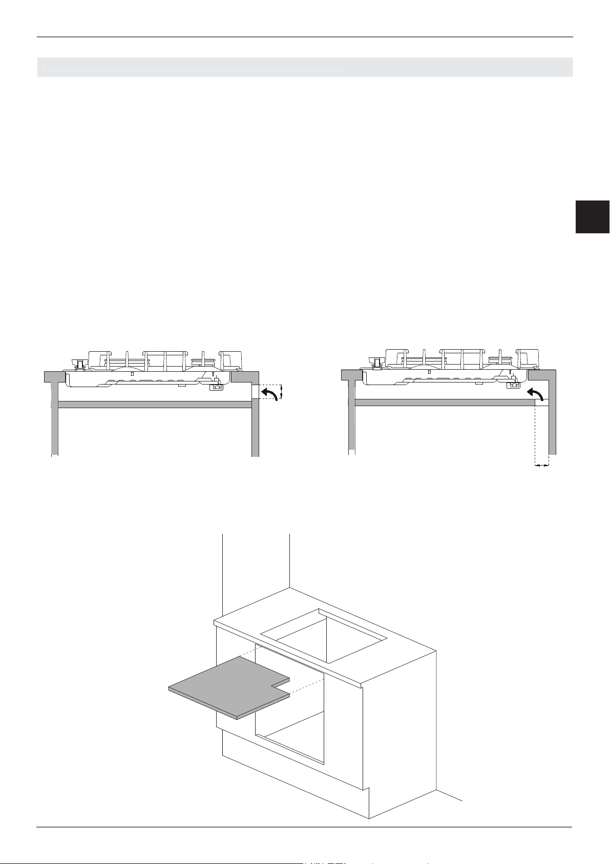
INSTALLING THE HOB ABOVE A CUPBOARD
OR DRAWERS
The clearance between the hob and the
kitchen units must be enough to ensure
suffi cient ventilation and air discharge. If there
are other units/furniture (side walls, drawers,
etc.), dishwashers or fridges under the hob, a
double-layer wooden base must be installed
at least 20 mm from the bottom of the hob
to avoid any accidental contact. It must only
be possible to remove the double-layer base
using special tools.
EN
40
7
/ Installation / Ventilation
EN
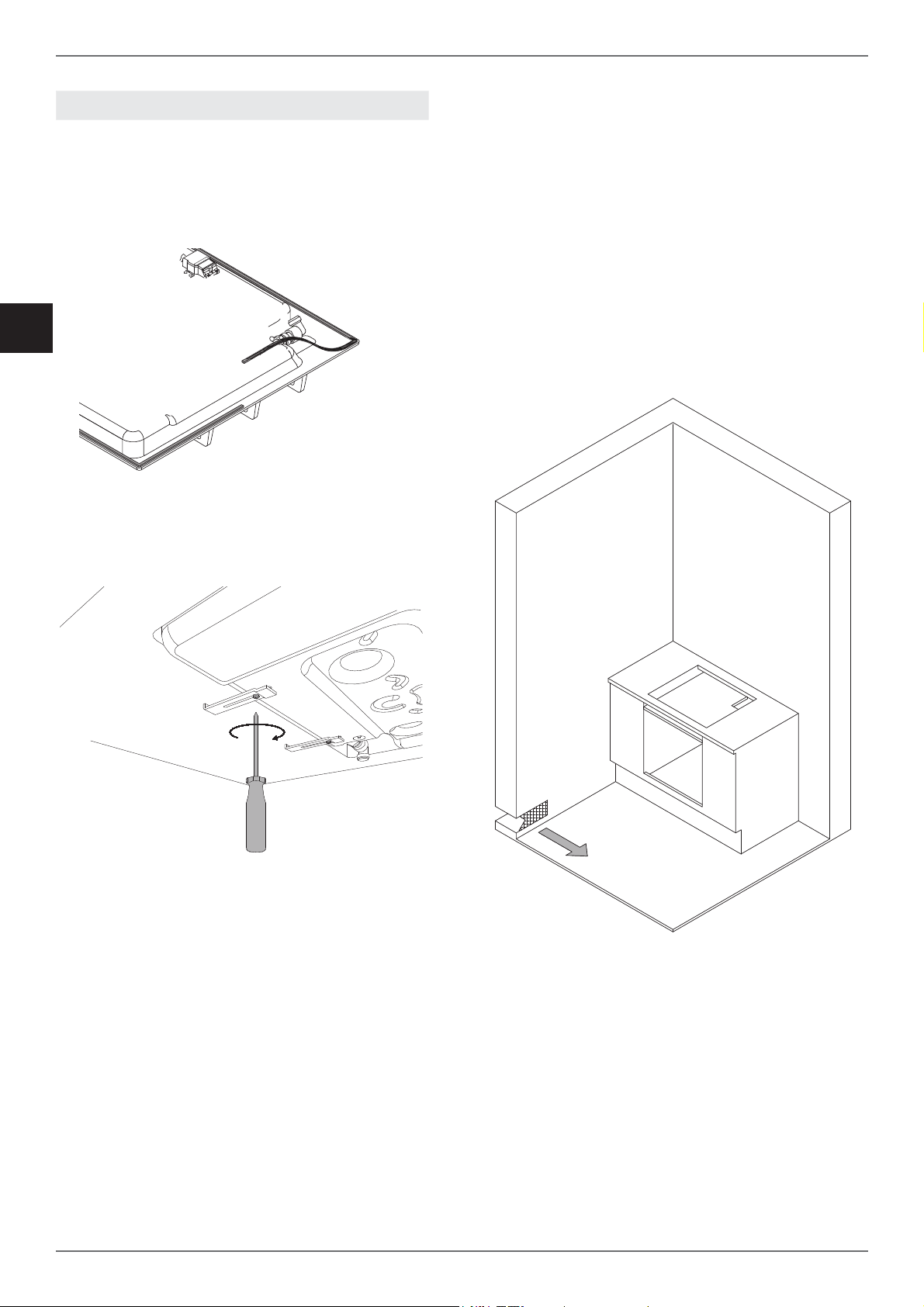
HOB FASTENING
In order to prevent accidental water ingress into
the unit below, the appliance is fi tted with a special
gasket.
1) Lay the sealing gasket out along the lower
edge of the built-in hob after cleaning the mating
surface.
2) Place the hob into the worktop cut-out.
3) To fasten the hob to the worktop, use a
screwdriver to install the four plates using the
corresponding screw in the bottom of the hob.
ROOM VENTILATION
In order to allow for correct appliance operation,
the room in which it is installed must have
continuous ventilation. The volume of the room
must be no less than 25 m³, and the quantity of
air required must be based on regular combustion
of the gas and the room ventilation. The natural
air fl ow must occur through permanent openings
in the wall of the room requiring ventilation; these
openings must lead directly outdoors, and must
have a minimum area of 100 cm².
Indirect ventilation via air taken from rooms
adjoining the one to be ventilated is also permitted,
as long as all applicable legislation is satisfi ed.
8
/ Ventilation / GAS
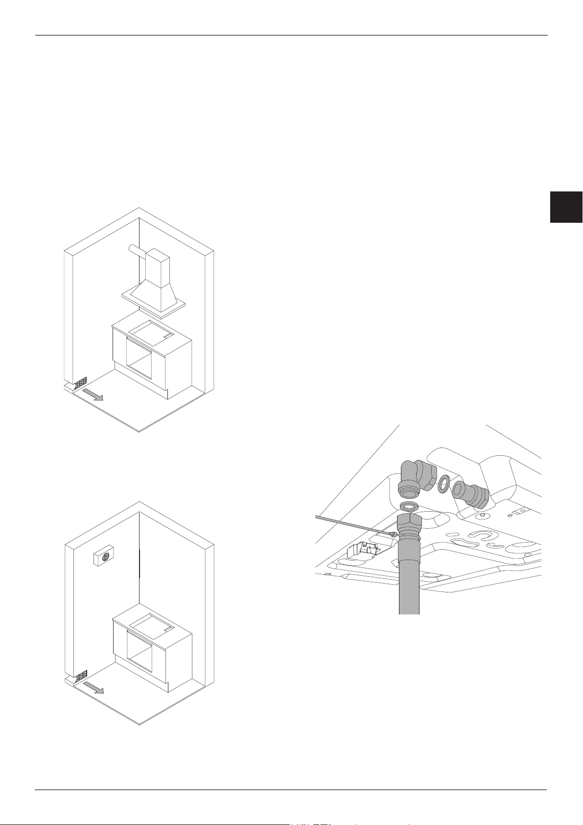
LOCATION AND VENTILATION
Gas cooking appliances must always have the
corresponding combustion products extracted
via cooker hoods connected to a fl ue or directly
to the outside (see Figure A). If it is not possible
to install a cooker hood, the use of an extractor
fan installed in a window or ducted directly outside
is permissible; this must be connected so as to
come on when the appliance is operational (see
Figure B), and all ventilation requirements laid out
in applicable legislation must be met.
CONNECTING THE APPLIANCE TO THE GAS
SUPPLY
Before connecting the appliance to the gas
supply, check that the data on the product
identifi cation label is compatible with the gas
supply specifi cations.
When the gas is supplied from the mains, the
appliance must be connected to the gas supply
with rigid copper tube or via a steel hose, in
accordance with applicable legislation.
When the gas is supplied from a cylinder, via a
compliant pressure regulator with continuouswall stainless-steel hose, it is advisable to install
a special after-market adapter on the hose to
facilitate connection with the hose barb of the
pressure regulator installed on the cylinder.
The hose must not pass through compartments
which may be fi lled, and must not come into
contact with moving components such as drawers.
On completing installation, check for any leaks
with a soapy solution, never with a fl ame.
EN
Figure A
WARNING: Remember that the appliance’s gas
inlet is a male 1/2” BSPP fi tting to ISO 228-1.
Figure B
9
EN
/ Gas
PRECAUTIONS WHEN USING THE PRODUCT
WITH LPG (BUTANE/PROPANE)
The gas taps installed on the hob must operate
with liquefi ed gas of controlled quality, supplied at
the correct nominal pressure.
This pressure must be guaranteed by a certifi ed
dedicated pressure regulator (not supplied with
the product).
The use of gas from uncertifi ed refi lls and/
or improper use of LPG cylinders, as well as
the corresponding regulator, can invalidate the
product warranty.
In particular, you must avoid all situations where
the gas could be polluted with residues and
impurities which, when they enter the gas circuit,
could
irreparably damage the control components such
as the taps and thermostats.
We therefore recommend:
• Using only LPG cylinders from offi cial resellers
authorised by the various manufacturers
• Using the cylinders until they are empty but
without tilting or overturning them
• Regularly cleaning the fi lter at the inlet to the
pressure regulator
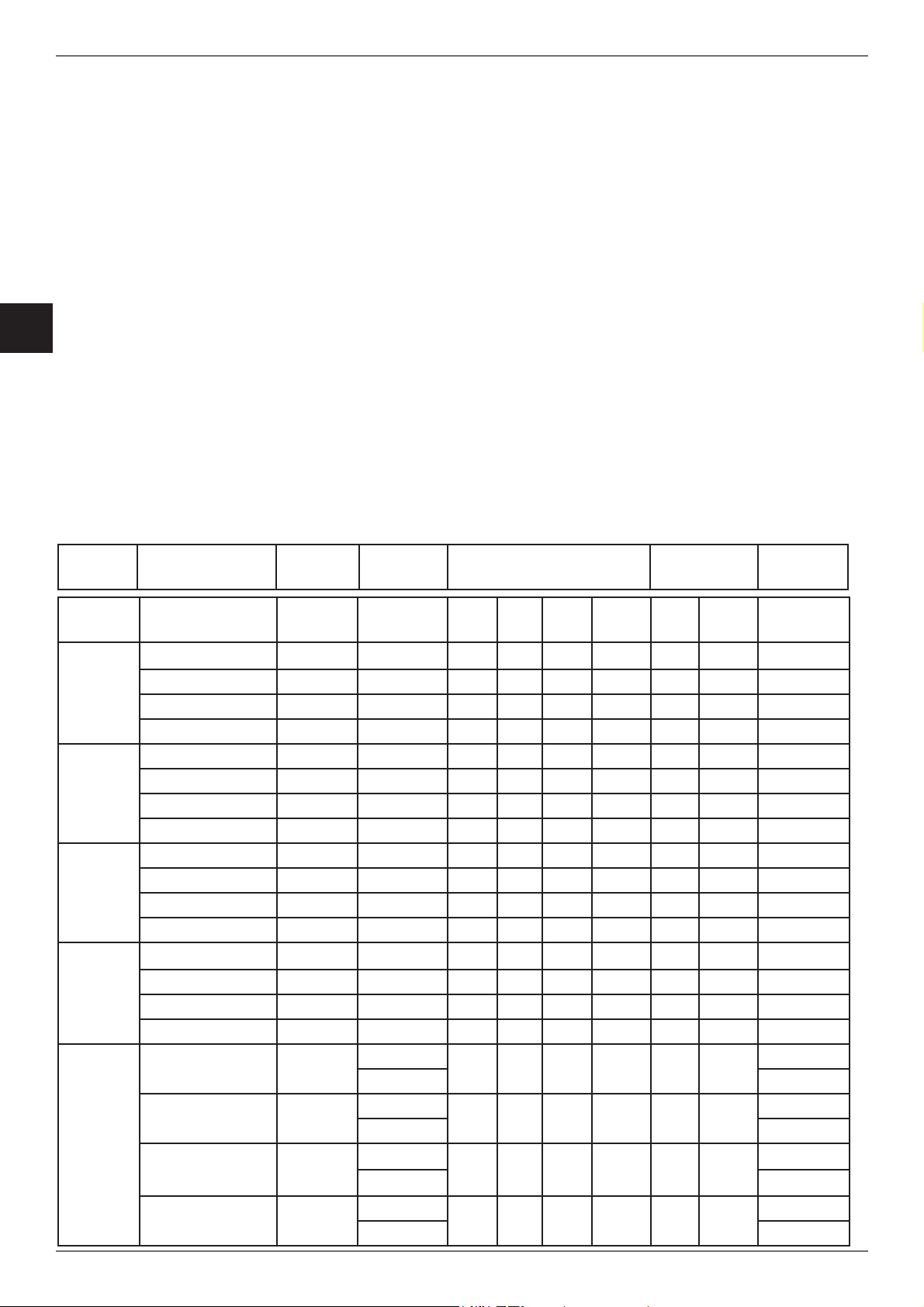
Regulating the appliance for various gas types
Burner Gas type Pressure Nozzle
diameter
mbar 1/100mm g/h l/h kW kcal/h kW kcal/h 1/100mm
Town gas G110 8 145 - 227 1.00 860 0.3 258 27 reg
Auxiliary
Semirapid
Rapid
Natural gas G20 20 77 - 95 1.00 860 0.3 258 27 reg
Butane G30 30 50 73 - 1.00 860 0.3 258 27
Propane G31 37 50 71 - 1.00 860 0.3 258 27
Town gas G110 8 192 - 397 1.75 1505 0.44 378 31 reg
Natural gas G20 20 101 - 167 1.75 1505 0.44 378 31 reg
Butane G30 30 66 127 - 1.75 1505 0.44 378 31
Propane G31 37 66 125 - 1.75 1505 0.44 378 31
Town gas G110 8 280 - 681 3 2580 0.75 645 42 reg
Natural gas G20 20 129 - 286 3 2580 0.75 645 42 reg
Butane G30 30 87 218 - 3 2580 0.75 645 42
Propane G31 37 87 214 - 3 2580 0.75 645 42
Town gas G110 8 350 - 907 4 3440 1.5 1250 65 reg
Nominal fl ow rate Flow rate
Reduced
Bypass
diameter
Crown
Dual
Wok
10
Natural gas G20 20 145 - 381 4 3440 1.5 1290 65 reg
Butane G30 30 101 290 - 4 3440 1.5 1290 65
Propane G31 37 101 286 - 4 3440 1.5 1290 65
Town gas G110 8
Natural gas G20 20
Butane G30 30
Propane G31 37
ext 2x250
- 953 4.2 3612 0.48 413
int 130 int 34 reg
ext 2x110
- 476 5.0 4300 0.48 413
int 70 int 34 reg
ext 2x69
334 - 4.6 4300 0.48 413
int 46 int 34
ext 2x69
328 - 4.6 3956 0.48 413
int 46 int 34
ext 65 reg
ext 65 reg
ext 65
ext 65
GAS CONVERSION
WARNING!
Isolate the appliance’s gas and electricity supplies
before performing any maintenance.
The gas conversion procedure involves two steps:
• Replacing the nozzles
• Burner minimum adjustment
/ Gas conversion
WARNING: After performing the above-mentioned
procedures, the technician must apply the label
corresponding to the new gas regulation to replace
the old one. This label is contained in the bag of
spare nozzles.
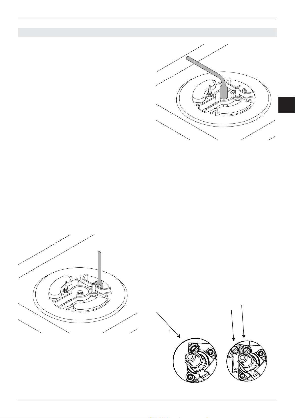
Step 1: Replacing the nozzles
Proceed as follows to change the burner nozzles:
lift the fl ame spreaders and unscrew the nozzles
using a 7 mm spanner, then replace them with
those required for new gas in accordance with the
TABLE (each nozzle has the number indicating its
diameter stamped on its body).
Keep the old nozzles in case they are required in
future.
EN
Step 2: Burner minimum adjustment
Light the nozzle and turn the knob to the MINIMUM
position (small fl ame).
2) Remove the knob, which is simply friction fi tted
to the spindle.
3) Use a small screwdriver on the gold screw next
to the knob shank (see fi gure) and turn the fl ow
control screw to the left or right until the burner
fl ame is suitably regulated to the MINIMUM
setting.
For dual burner knobs there are two fl ow control
screws: screw A to adjust the inner ring, and screw
B to adjust the outer ring.
4) Ensure that, when moving from the MAXIMUM
to the MINIMUM position, the fl ame does not go
out.
WARNING: The above-mentioned regulation
must only be performed for burners running on
natural gas (methane): when using LPG (butane
or propane), the screw must be locked all the way
to the right.
A
B
11
/ Electrical connection / Maintenance
EN
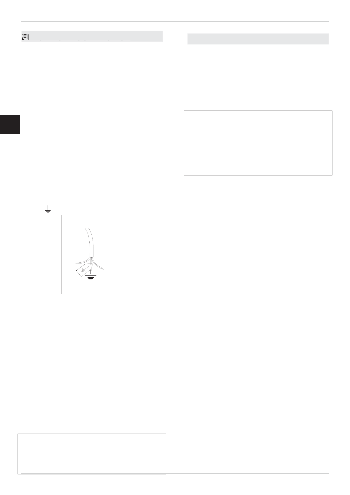
ELECTRICAL CONNECTION
The electrical connection must be made in
accordance with applicable standards and
legislation.
Before connecting up the appliance, check that:
• The mains electricity supply matches the
characteristics indicated on the appliance
data plate.
• The circuit wiring and outlet are equipped with
a compliant earth connection.
When the oven is connected to the mains power
supply via a socket:
• Wire a plug onto the power cable which
must comply with applicable standards in the
country of use; the plug (and its fuse, where
applicable) must be suitable for the rated load
specifi ed on the appliance data plate. Connect
the cores of the cable in accordance with the
fi gure, ensuring you follow the harmonised
wiring colour scheme:
L (live/hot/phase) = brown wire
N (neutral) = blue wire
earth ”
” symbol = yellow/green wire
MAINTENANCE
REPLACING COMPONENTS
Isolate the appliance’s gas and electricity supplies
before performing any maintenance.
Contact an authorised service centre if functional
components such as burners, taps and electrical
components require replacement.
WARNING:
If the power cable requires replacement, the
installer/maintenance technician must use
H05VV-F 3x0.75 mm
conductor around 2 cm longer than the live
and neutral wires. They must also comply with
the instructions given for the initial electrical
connection.
2
cable and leave the earth
L
N
• The power cable must be positioned in such
a way that it does not reach a temperature of
90°C at any point.
• Do not use adapters, extension leads, gang
sockets etc. as these could cause loose
contacts and overheat.
When the appliance is to be hard-wired to the
mains circuit:
• The circuit must be fi tted with a omnipolar
circuit breaker of suitable capacity for the
appliance's rated load.
• The earth conductor must not be switched
by the breaker and must be connected to the
earthing system.
• As an alternative, an RCBO may also be used,
or RCD protection in addition to or instead of
a fuse or MCB, depending on the applicable
electrical code.
WARNING: The appliance complies with the
requirements of 2016/426/EU (Gas Appliances
Regulation), 2014/35/EU (Low Voltage
Directive) on electrical safety, and 2014/30/EU
(Electromagnetic Compatibility Directive).
12
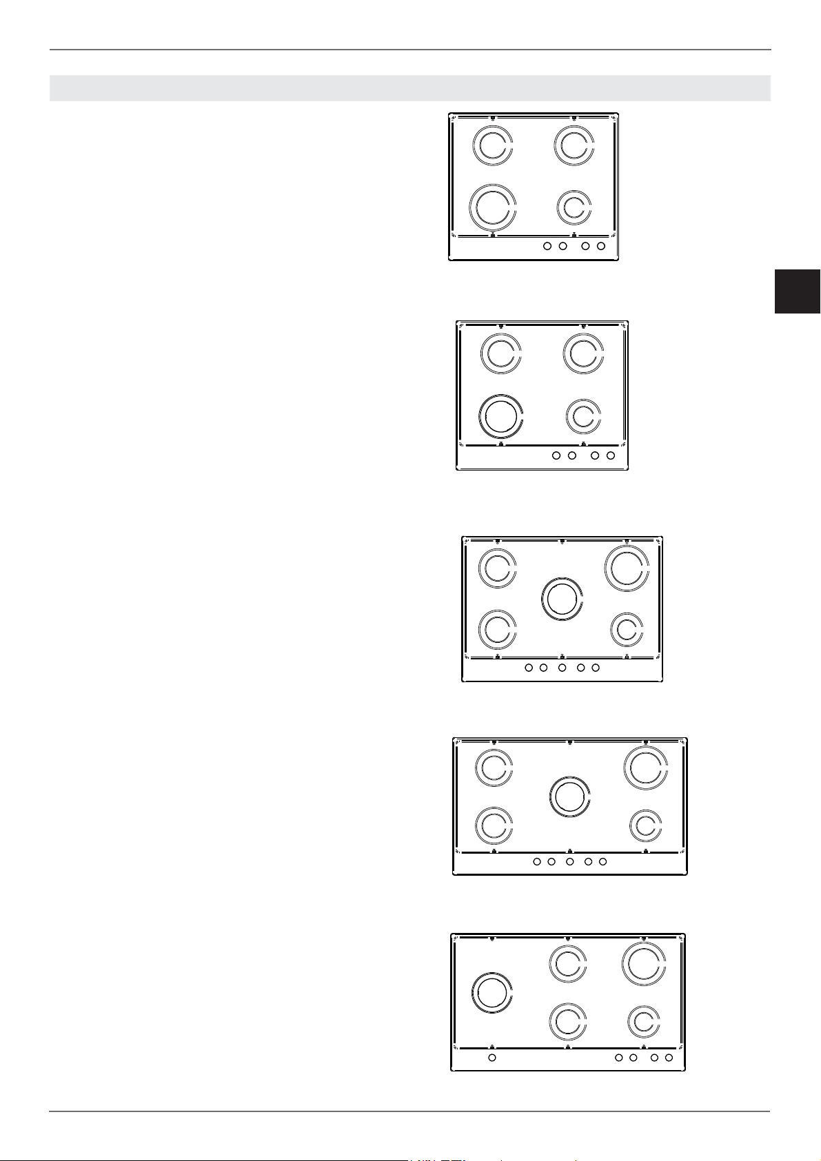
DESCRIPTION OF HOBS
/ Description of Hobs
CONTROLS / BURNERS
1 Front right auxiliary burner
2 Rear right semi-rapid burner
3 Rear left semi-rapid burner
4 Front left rapid burner
CONTROLS / BURNERS
1 Front right auxiliary burner
2 Rear right semi-rapid burner
3 Rear left semi-rapid burner
4 Front left crown burner
EN
CONTROLS / BURNERS
1 Front right auxiliary burner
2 Rear right rapid burner
3 Central crown burner
4 Rear left semi-rapid burner
5 Front left semi-rapid burner
CONTROLS / BURNERS
1 Front right auxiliary burner
2 Rear right rapid burner
3 Central dual burner or crown burner
4 Rear left semi-rapid burner
5 Front left semi-rapid burner
CONTROLS / BURNERS
4
5
3
5 4 3 2 1
3
2
1
2
1 Front right auxiliary burner
2 Rear right rapid burner
3 Rear central semi-rapid burner
4 Front central semi-rapid burner
5 Left side dual burner or crown burner
5
4
5 4 3 2 1
1
13
/ Use
EN
USE
BURNERS AND GRATES
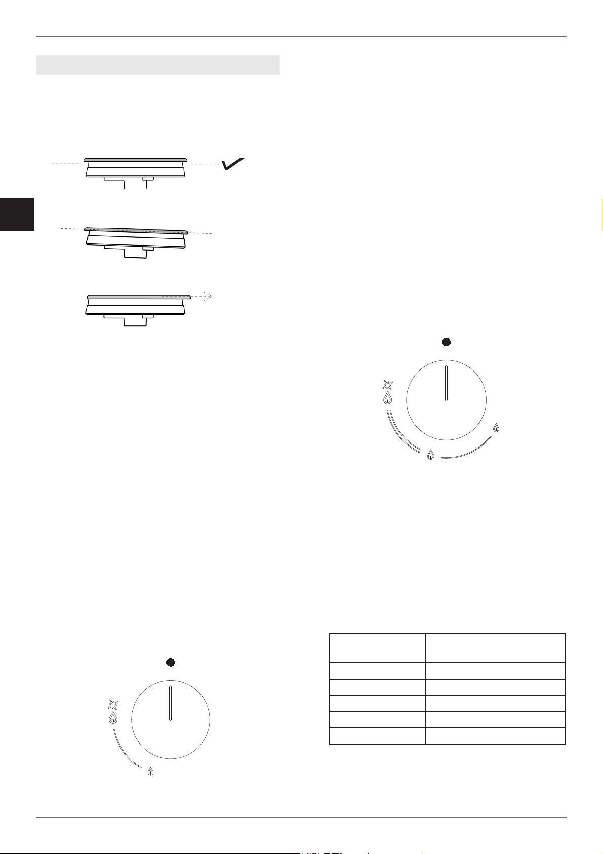
The fl ame spreaders and burner caps must be
correctly positioned in order for the hob to operate
properly.
X
X
USING DUAL BURNERS (where applicable)
Dual burners off er greater fl exibility, as it is
possible to light both rings or just the inner ring.
Turn the corresponding knob to the left to the
MAXIMUM position (1).
Press the knob to start the gas fl ow and ignite the
burner.
When the burner lights, keep the knob held down
for around ten seconds, then release.
If the burner goes out after releasing the knob,
repeat the entire operation.
In position 2 the outer ring is at the minimum
setting and the ring crown is at the maximum.
In position 3 the inner ring is at the maximum
setting and the outer ring is off .
In position 4 the inner ring is at the minimum
setting and the outer ring is off .
Incorrect positioning of the fl ame spreaders and
caps can lead to burner damage.
The grids must be positioned in their seats inside
the hob.
USING THE BURNERS
Next to each knob is an indication of which burner
it operates.
Turn the knob corresponding to the selected
burner to the left to the MAXIMUM position (large
fl ame).
Press the knob to start the gas fl ow and ignite the
burner.
When the burner lights, keep the knob held down
for around ten seconds, then release.
If the burner goes out after releasing the knob,
repeat the entire operation.
To shut off the burner, turn the knob to the right to
the zero position.
Tips for optimum burner use:
• Use appropriate pans for each burner (see
table).
• When the pan boils, move the knob to the
MINIMUM position.
• Always use pans with lids.
BURNER PAN DIAMETER
(RECOMMENDED) cm
Auxiliary 12 - 14
Semi-rapid 14 - 26
Rapid 18 - 26
Crown 22 - 26
Dual 22 -26
14

/ Use / Cleaning
E
SAFETY SYSTEMS
A fl ame sensor (thermocouple) is installed on
each burner to prevent gas from coming out if the
fl ame is accidentally extinguished.
If there is a blackout of the electricity supply, the
hob will keep working without any danger.
MANUAL IGNITION
In the event of a power failure, the burners can be
ignited manually.
Turn the knob corresponding to the selected
burner to the left to the MAXIMUM position (large
fl ame).
Press down on the knob to start the fl ow of gas,
then bring a lighter or fl ame up to the burner.
When the burner lights, keep the knob held down
for around ten seconds, then release.
ACCESSORIES
Wok Adapter
Supplementary grid to be used on crown burners
with concave-bottom cookware.
Coff ee Pot Reducer
Supplementary grid to be used on the auxiliary
burner for coff ee pots or cookware with a diameter
below 12 cm.
CLEANING THE APPLIANCECLEANING THE APPLIANC
Before performing any cleaning operation, wait
for all parts to cool down and isolate the hob’s
electricity and gas supply.
Cleaning the hob:
The burner heads, enamelled steel grids,
enamelled caps and fl ame spreaders must be
regularly cleaned with warm soapy water then
rinsed and dried thoroughly.
Any liquid which should overfl ow from the
cookware must always be removed with a cloth.
If it is diffi cult to open or close one of the gas taps,
do not force it! Request urgent assistance from
the technical support network.
Cleaning Enamelled Parts:
To maintain the characteristics of the enamelled
components, they should be cleaned frequently
with soapy water. Never use scouring powders.
Do not leave acidic or basic substances (vinegar,
lemon juice, salt, tomato juice etc.) sitting on
enamelled parts, and do not wash enamelled
parts when they are still hot.
Cleaning Stainless-Steel Parts
Clean the components with soapy water and
then dry them with a soft cloth. The shine can be
maintained by periodic use of commonly available
products. Never use scouring powders or pads.
Cleaning the Burner Flame Spreaders:
As they are simply resting in position, they can
be cleaned simply by removing them from their
seats and washing them with soapy water. Do not
immerse in water or wash them under running
water. After drying them thoroughly and checking
that the holes are not blocked, return them to their
correct position.
Cleaning Glass Hobs:
To degrease, use washing-up liquid and vinegar,
then rinse; otherwise, clean with washing-up
liquid, rinse, then pass over with a moist cloth
before drying.
To remove encrusted food, soak with soapy water
or washing-up liquid for a few minutes. After a few
minutes, rinse and wash the hob.
Avoid anti-limescale, abrasive and multi-purpose
products, as they will aff ect the look of the glass
after a while.
Cleaning the Hob Grids:
Do not wash the grids in the dishwasher.
White residue on the grids is due to normal contact
with cookware, and not indicative or defects or
abrasions in the enamel.
EN
15

EN
/ Troubleshooting
TROUBLESHOOTING
In some cases operational faults can be easily
resolved.
Read the following tips before contacting technical
support.
The burner does not light.
Check that there is no food residue between the
igniter and burner.
Check that the gas and electricity supplies are
present.
Check that the burners are correctly located and
are not wet.
The igniter is still not working.
Water has probably entered the hob during
cleaning. Isolate the electricity supply and wait a
few hours to allow it to dry thoroughly.
The igniter does not work
Check that the electrical isolation switch or circuit
breaker is in the on position, and that there are no
problems with the electricity supply.
The burner fl ame is not even.
The burner is not correctly positioned.
The burner holes are dirty or blocked by water.
The knob will not stay in place.
The knob clip is broken: call customer service for
a replacement.
There is no gas fl ow.
Check that the gas isolation tap is not closed/the
cylinder is not empty.
WARRANTY AND CUSTOMER SERVICE:
WWW.BERTAZZONI.COM
16

INSTRUCTIONS D’INSTALLATION ET D’UTILISATION
PLAQUES DE CUISSON ENCASTRABLES AU GAZ
TYPE P93V (MÉTAL)
TYPE P94GV (VERRE)
FR
3100419
WWW.BERTAZZONI.COM

/ Table des matières
TABLE DES MATIÈRES
FR
AVERTISSEMENTS _____________________________________________________________
RESPONSABILITÉ DU FABRICANT _______________________________________________
PROTECTION DE L’ENVIRONNEMENT ____________________________________________
CONSIGNES GÉNÉRALES DE SÉCURITÉ _________________________________________
AVERTISSEMENTS D’UTILISATION ______________________________________________
PLAQUE D’IDENTIFICATION ____________________________________________________
EMBALLAGES EN PLASTIQUE __________________________________________________
MANUEL TECHNIQUE POUR L’INSTALLATEUR ______________________________________
INTÉGRATION DE LA PLAQUE DE CUISSON ______________________________________
AVERTISSEMENTS IMPORTANTS _______________________________________________
INSTALLATION AU-DESSUS D’UN FOUR ENCASTRÉ _______________________________
INSTALLATION AU-DESSUS D’UN LOGEMENT OU DE TIROIRS _______________________
FIXATION DE LA PLAQUE DE CUISSON ____________________________________________
VENTILATION AMBIANTE _______________________________________________________
EMPLACEMENT ET AÉRATION __________________________________________________
RACCORDEMENT DE LA PLAQUE À L’ALIMENTATION EN GAZ _______________________
PRÉCAUTIONS D’UTILISATION DU PRODUIT AVEC DU GAZ GPL ______________________
CONVERSION DU GAZ _________________________________________________________
BRANCHEMENT ÉLECTRIQUE ___________________________________________________
ENTRETIEN ___________________________________________________________________
REMPLACEMENT DES COMPOSANTS ____________________________________________
4
4
4
5
5
5
5
6
6
6
7
7
8
8
9
9
10
11
12
12
12
DESCRIPTION DES PLAQUES DE CUISSON _________________________________________
UTILISATION __________________________________________________________________
BRÛLEURS ET GRILLES ________________________________________________________
UTILISATION DES BRÛLEURS ___________________________________________________
SYSTÈME DE SÉCURITÉ ________________________________________________________
ALLUMAGE MANUEL ___________________________________________________________
ACCESSOIRES ________________________________________________________________
NETTOYAGE DE L’APPAREIL _____________________________________________________
DYSFONCTIONNEMENT _________________________________________________________
13
14
14
14
15
15
15
15
16
2

/ Message du Président
MESSAGE DU PRÉSIDENT
Cher nouveau propriétaire d’un produit Bertazzoni,
Je tiens à vous remercier d’avoir choisi l’un de nos magnifi ques produits pour
votre habitation.
Ma famille s’est lancée dans la fabrication d’équipements de cuisine en Italie
en 1882, se bâtissant ainsi une solide réputation en termes de qualité de
conception ainsi qu’une véritable passion pour la gastronomie.
Aujourd’hui, nos produits se distinguent de leurs concurrents puisqu’ils
représentent l’incroyable union d’un design purement italien et d’une
technologie d’avant-garde. Notre mission est de réaliser des produits qui
fonctionnent parfaitement et procurent du plaisir à leurs utilisateurs.
En réalisant des produits à l’esthétique sans pareille, nous répondons aux
attentes de nos clients en matière de design irréprochable. En réalisant des
produits polyvalents et simples à utiliser, cuisiner avec Bertazzoni devient un
vrai plaisir.
Le présent manuel vous aidera à utiliser et à entretenir de la manière la plus
sûre et effi cace le produit Bertazzoni dont vous avez fait l’achat, de sorte qu’il
puisse vous apporter la plus grande satisfaction lors des années à venir.
Nous vous souhaitons de profi ter pleinement de toutes ses possibilités !
Paolo Bertazzoni
Président
FR
3

/ Avertissements
AVERTISSEMENTS
FR
VEILLER À LIRE LES PRÉSENTES
INSTRUCTIONS AVANT D’INSTALLER ET
D’UTILISER L’APPAREIL.
Les présentes instructions sont valables
uniquement dans les pays auxquels elles sont
destinées, dont les symboles d’identifi cation
fi gurent sur l’étiquette d’identifi cation de l’appareil.
Le fabricant ne saurait être tenu pour responsable
des éventuels dommages matériels et/ou
corporels causés par une mauvaise installation
ou par une mauvaise utilisation de l’appareil.
Le fabricant décline toute responsabilité en cas
d’inexactitudes dues à des erreurs d’impression
ou de transcription présentes dans le présent
manuel. La représentation des fi gures présentes
dans le manuel est purement indicative. Le
fabricant se réserve la faculté d’apporter à ses
produits les modifi cations jugées nécessaires ou
utiles sans que les caractéristiques essentielles
de sécurité et de fonctionnement ne soient
aucunement altérées.
L’APPAREIL OBJET DU PRÉSENT MANUEL
N’A PAS ÉTÉ CONÇU POUR UN USAGE
PROFESSIONNEL MAIS POUR UN USAGE
DOMESTIQUE.
Le présent manuel d’utilisation fait partie intégrante
de l’appareil, il doit être conservé intact et doit
rester à portée de main de l’utilisateur pendant
tout le cycle de vie de l’appareil. Avant d’utiliser
l’appareil, veiller à lire le présent manuel.
RESPONSABILITÉ DU FABRICANT
Le fabricant décline toute responsabilité en cas de
dommages corporels et/ou matériels causés par :
• une utilisation de l’appareil autre que celle
prévue ;
• le non-respect des prescriptions fi gurant dans
le présent manuel d’utilisation ;
• la modifi cation de toute partie de l’appareil
quelle qu’elle soit ;
• l’utilisation de pièces détachées non d’origine.
• L’appareil objet du présent manuel est destiné
à la cuisson d’aliments dans un environnement
domestique. Toute autre utilisation doit être
considérée comme impropre.
• L’appareil n’est pas conçu pour fonctionner
en étant relié à des timers externes ni à des
systèmes de commande à distance.
PROTECTION DE L’ENVIRONNEMENT
Veiller à éliminer les emballages
dans le respect de l’environnement.
L’appareil objet du présent manuel est marqué
conformément à la directive européenne 2012/19/
UE en matière de déchets d’équipements
électriques et électroniques (DEEE).
Cette directive défi nit les normes de collecte et
de recyclage des équipements hors d’usage
applicables dans toute l’Union européenne.
L’emballage de l’appareil est constitué des
éléments strictement nécessaires afi n de garantir
une protection effi cace pendant son transport.
Les matériaux d’emballage sont entièrement
recyclables, aussi leur impact sur l’environnement
est minime. Le fabricant invite à contribuer à la
protection de l’environnement en respectant entre
autres les conseils suivants :
• éliminer les éléments et matériaux d’emballage
dans les conteneurs de tri prévus à cet eff et ;
• avant de remettre l’appareil à éliminer à
un centre de collecte, veiller à le rendre
inutilisable ; s’informer auprès des services
locaux compétents afi n de connaître le centre
de collecte des matériaux recyclables le plus
proche auquel l’appareil peut être remis ;
• ne pas éliminer les huiles usées dans un
lavabo ; les conserver dans un récipient fermé
et les remettre à un centre de collecte ou,
en cas d’impossibilité, les éliminer avec les
ordures ménagères (de sorte qu’elles soient
éliminées dans une décharge contrôlée ; bien
qu’il ne s’agisse pas de la meilleure solution,
cela permet de prévenir la contamination des
eaux).
ATTENTION : en apposant le marquage
le produit objet du présent manuel, le fabricant
certifi e, en engageant sa seule responsabilité,
la conformité de l’appareil à toutes les normes
européennes de sécurité, de santé et de protection
de l’environnement.
4
sur

AVERTISSEMENTS
/ Avertissements
CONSIGNES GÉNÉRALES DE SÉCURITÉ
• L’appareil et ses parties accessibles
deviennent très chauds pendant l’utilisation.
• Ne pas toucher les éléments chauff ants
pendant l’utilisation.
• Ne pas laisser d’enfants de moins de 8 ans à
proximité de l’appareil à moins qu’ils ne soient
constamment surveillés.
• Les enfants ne doivent pas jouer avec
l’appareil.
• L’appareil peut être utilisé par des enfants à
partir de 8 ans et par des personnes à capacités
physiques, sensorielles ou mentales réduites
ou bien ne possédant pas l’expérience ni les
connaissances nécessaires, à condition que
ce soit sous surveillance ou d’avoir reçu les
instructions nécessaires de personnes adultes
et responsables de leur sécurité.
• Pendant l’utilisation, ne pas poser d’objets
métalliques sur l’appareil : ils pourraient
devenir incandescents.
• Après utilisation, éteindre l’appareil.
• Ne pas tenter d’éteindre une fl amme/un
incendie avec de l’eau : éteindre l’appareil et
recouvrir la fl amme à l’aide d’un couvercle ou
d’une couverture ignifuge.
• Les opérations de nettoyage et d’entretien ne
doivent pas être confi ées à des enfants sans
surveillance.
• S’assurer que les surfaces aient refroidi avant
de procéder au nettoyage de l’appareil.
• Confi er l’installation et les interventions
d’assistance à un personnel qualifi é
conformément aux normes en vigueur. Ne
jamais tenter de réparer soi-même l’appareil
ou sans l’assistance d’un technicien qualifi é.
• Ne pas modifi er l’appareil.
• Ne pas introduire d’objets dans les fentes.
• Ne pas obstruer les ouvertures ni les orifi ces
de ventilation et de dissipation de la chaleur.
• Dans le cas où le câble d’alimentation
électrique serait endommagé, contacter
aussitôt le service d’assistance technique
pour en eff ectuer le remplacement.
• Sur les parties en verre, ne pas utiliser de
détergents abrasifs ou corrosifs (par exemple
des produits en poudre, des détachants et des
éponges métalliques).
• Ne pas s’asseoir sur l’appareil.
• Ne pas utiliser de vapeur pour nettoyer
l’appareil.
• Ne pas laisser d’objets sur les surfaces de
cuisson.
• N’utiliser en aucun cas l’appareil comme
source de chauff age ambiant.
• En cas de rupture, de fêlure et/ou de fi ssure de
la plaque en verre, éteindre immédiatement
tous les brûleurs et débrancher la plaque
de cuisson de l’alimentation en gaz et en
électricité. S’adresser au service d’assistance.
• Les brusques variations de température
peuvent provoquer la rupture du verre ; aussi,
ne pas verser de liquides froids sur la plaque
de cuisson pendant son utilisation.
• Les récipients endommagés, de dimensions
inadaptées, dépassant des bords de la plaque
de cuisson ou mal positionnés peuvent causer
de graves blessures.
• L’utilisation de la plaque de cuisson à gaz
génère de la chaleur, de l’humidité et des
produits de combustion ; veiller à bien ventiler
la pièce pendant le fonctionnement.
AVERTISSEMENTS D’UTILISATION
• Utiliser des récipients de cuisson à fond plat.
• Positionner les casseroles avant d’allumer le
feu.
• Ne pas s’éloigner pendant la cuisson des
aliments eff ectuée avec de l’huile ou autres
matières grasses : celles-ci peuvent facilement
s’enfl ammer.
• Ne pas utiliser de sprays à proximité de la
plaque lorsqu’elle est allumée.
• Régler la fl amme de sorte qu’elle ne dépasse
pas des limites de la casserole pour ne pas en
endommager les poignées.
• Ne pas poser de casseroles directement sur
les brûleurs.
• S’assurer que la casserole est centrée par
rapport au brûleur.
PLAQUE D’IDENTIFICATION
Sur la plaque d’identifi cation fi gurent les données
techniques, le numéro de série et le marquage.
La plaque d’identifi cation se trouve sur le carter
inférieur et ne doit en aucun cas être retirée (une
copie de cette plaque fi gure dans le manuel).
EMBALLAGES EN PLASTIQUE
Risque d’étouff ement
• Ne pas laisser les emballages ou parties de
ceux-ci sans surveillance.
• Ne pas laisser d’enfants jouer avec les sachets
en plastique de l’emballage.
FR
5

/ Installation
MANUEL TECHNIQUE POUR L’INSTALLATEUR
ANUEL TECHNIQUE POUR L’INSTALLATEUR
FR
L’installation, tous les réglages, les modifi cations
et les interventions d’entretien indiqués dans
la présente section doivent être exclusivement
confi és à un personnel qualifi é (conformément
aux normes en vigueur). Une mauvaise
installation peut causer des dommages corporels
(aux personnes et aux animaux) ainsi que des
dommages matériels dont le fabricant ne saurait
être tenu pour responsable. Pendant le cycle de
vie de l’équipement, les dispositifs de sécurité ou
de réglage automatique des appareils peuvent
être modifi és uniquement par le fabricant ou par
le fournisseur dument autorisé à cet eff et.
Procéder à l’installation uniquement après
s’être muni des équipements de protection
individuelle.
INTÉGRATION DE LA PLAQUE DE CUISSON
Après avoir retiré les diff érentes parties mobiles
de leur emballage interne et externe, s’assurer
que la plaque de cuisson est intacte. Au moindre
doute, ne pas utiliser le four et contacter le centre
d’assistance. Compte tenu des dimensions
critiques de l’appareil (voir tableaux), réaliser une
ouverture dans le plan du meuble (voir fi gure)
en respectant les dimensions fi gurant dans le
tableau.
A (cm) B (cm) H (cm) L (cm)
Plaque de 60 cm 56 48 60,5 52,5
Plaque de 75 cm 56 48 75,5 52,5
Plaque de 90 cm 85 48 89,3 52,5
AVERTISSEMENTS IMPORTANTS
La plaque de cuisson peut être insérée entre
des meubles de cuisine ou entre un meuble et
la paroi en dur. La paroi arrière et les surfaces
environnantes doivent résister à une température
de 90 °C. Pour éviter que le plastique laminé qui
recouvre le meuble ne se décolle, la colle utilisée
doit résister à une température d’au moins 150 °C.
L’installation de l’appareil doit être eff ectuée
conformément aux prescriptions des normes en
vigueur.
L’appareil n’est pas relié à des dispositifs
d’expulsion des produits de combustion. Il doit
donc être raccordé conformément aux règles
d’installation susmentionnées. Il est notamment
nécessaire de veiller à bien respecter les
prescriptions en matière d’aération et de ventilation
de l’espace.
Le plan du meuble doit être en mesure de
supporter une température maximale de
90 °C (120 °C pour la version de 75 cm)
C min. (cm) 8,5 M (cm) 4,4
D min. (cm) 3 N (cm) 1,1
E min. (cm) 18 P (cm) 47,4
F min. (cm) 70 Q (cm) 4
G min. (cm) 8,5
M
NPQ
H
'
*
(
$
L
)
&
%
6

MANUEL TECHNIQUE POUR L’INSTALLATEUR
ANUEL TECHNIQUE POUR L’INSTALLATEUR
/ Installation
INSTALLATION AU-DESSUS D’UN FOUR
ENCASTRÉ
La distance entre la plaque de cuisson et les
meubles de cuisine ou les appareils encastrés
doit garantir une ventilation et une évacuation
de l’air suffi santes.
En cas d’installation au-dessus d’un four, il
est nécessaire de maintenir un espace entre
le dessous de la plaque de cuisson et la partie
supérieure de l’appareil installé au-dessous
ainsi que de garantir la ventilation de tout le
logement (comme indiqué sur la fi gure).
Le four doit être doté d’un système de
refroidissement. Le fabricant décline toute
responsabilité en cas d’installation sur un four
d’une autre marque.
INSTALLATION AU-DESSUS D’UN LOGEMENT
OU DE TIROIRS
La distance entre la plaque de cuisson et les
meubles de cuisine doit garantir une ventilation
et une évacuation de l’air suffi santes. En
présence d’autres meubles (parois latérales,
tiroirs, etc.), lave-vaisselle ou réfrigérateur,
sous la plaque de cuisson, il est nécessaire
d’installer un double fond en bois à une
distance d’au moins 20 mm du dessous de
la plaque de cuisson pour éviter tout contact
accidentel. Le retrait du double fond doit être
possible uniquement à l’aide d’outils prévus à
cet eff et.
FR
40
40
7

/ Installation / Ventilation
FR
FIXATION DE LA PLAQUE DE CUISSON
Pour prévenir les infi ltrations accidentelles
de liquides dans le meuble situé au-dessous,
l’appareil est doté d’un joint spécifi que.
1) Appliquer le joint d’étanchéité le long du bord
inférieur du plan d’encastrement après en avoir
nettoyé la surface.
2) Introduire la plaque dans l’ouverture du meuble.
3) Pour fi xer la plaque au plan, visser les 4 pattes
sur la partie inférieure de la plaque au moyen d’un
tournevis et des vis prévues à cet eff et.
VENTILATION AMBIANTE
Pour garantir le bon fonctionnement de l’appareil,
il est nécessaire que la pièce dans laquelle il est
installé soit constamment ventilée. Le volume de
la pièce ne doit pas être inférieur à 25 m³ et la
quantité d’air doit être fonction de la combustion
régulière du gaz et de la ventilation de la pièce.
Le fl ux d’air naturel doit être garanti par des
ouvertures permanentes réalisées sur les murs
de la pièce à ventiler : ces ouvertures doivent
donner sur l’extérieur et leur section doit être au
minimum de 100 cm².
La ventilation indirecte est également admise, par
prélèvement d’air dans les pièces mitoyennes à la
pièce à ventiler, en veillant dans ce cas à respecter
scrupuleusement les normes en vigueur.
8

/ Ventilation / GAZ
EMPLACEMENT ET AÉRATION
Les produits de combustion des appareils de
cuisson à gaz doivent toujours être expulsés au
moyen de hottes reliées à une cheminée, à un
conduit ou bien directement à l’extérieur (voir
fi gure A). Dans le cas où l’utilisation d’une hotte
s’avérerait impossible, il est possible d’utiliser un
ventilateur installé sur une fenêtre ou donnant
directement sur l’extérieur, à mettre en marche
lorsque l’appareil est utilisé (voir fi gure B), à
condition de respecter scrupuleusement les
dispositions relatives à la ventilation des normes
en vigueur.
RACCORDEMENT DE LA PLAQUE À
L’ALIMENTATION EN GAZ
Avant de raccorder l’appareil à l’alimentation
en gaz, s’assurer que les données fi gurant sur
l’étiquette d’identifi cation sont compatibles avec
celles du réseau de distribution de gaz.
Lorsque le gaz est distribué au moyen de
conduites, l’appareil doit être raccordé au
circuit d’adduction de gaz au moyen d’un tuyau
métallique rigide en cuivre ou d’un tuyau fl exible
en acier conformément aux normes en vigueur.
Lorsque le gaz provient d’une bonbonne, l’appareil
doit être alimenté au moyen d’un régulateur de
pression conforme aux normes en vigueur et
de tuyaux fl exibles en acier inoxydable à paroi
continue. Sur le tuyau fl exible, il est recommandé
d’installer un adaptateur spécial, disponible dans
le commerce, afi n de faciliter la jonction avec le
raccord du régulateur de pression monté sur la
bonbonne.
FR
Le tuyau ne doit pas traverser d’espaces pouvant
être encombrés et ne doit en aucun cas se trouver
au contact de parties mobiles, comme des tiroirs.
Une fois l’installation terminée, s’assurer de
l’absence de fuites au moyen d’une solution
savonneuse et en aucun cas à l’aide d’une
fl amme.
Figure A
ATTENTION : il est rappelé que le raccord
d’arrivée de gaz de l’appareil est pourvu d’un
fi letage 1/2 gaz cylindrique mâle conforme aux
normes UNI-ISO 228-1.
Figure B
9

/ Gaz
FR
PRÉCAUTIONS D’UTILISATION DU PRODUIT
AVEC DU GAZ GPL
Les robinets de gaz montés sur la plaque de
cuisson doivent fonctionner avec du gaz liquide à
qualité contrôlée, distribué à la pression nominale
prévue.
Cette pression doit être garantie au moyen d’un
régulateur de pression certifi é (non fourni avec le
produit).
L’utilisation de gaz provenant de recharges non
certifi ées et/ou l’utilisation inappropriée de la
bonbonne de GPL et du régulateur correspondant
peuvent invalider la garantie du produit.
Il est en particulier nécessaire d’éviter toutes les
situations susceptibles de polluer le gaz avec des
résidus et des impuretés qui, introduits dans le
circuit de gaz, peuvent
endommager irréparablement les éléments de
contrôle tels que les robinets et les thermostats.
Adaptation aux diff érents types de gaz
Brûleur Type de gaz Pression Diamètre
de la buse
Aussi, il est recommandé :
• d’utiliser uniquement des bonbonnes de GPL
provenant de revendeurs offi ciels et agréés par
les fabricants.
• d’utiliser les bonbonnes jusqu’à ce qu’elles soient
vides, sans jamais les incliner ni les retourner.
• de nettoyer régulièrement le fi ltre présent à
hauteur de l’arrivée du régulateur de pression.
Débit nominal Débit
réduit
Diamètre
bypass
mbar 1/100 mm g/h l/h kW kcal/h kW kcal/h 1/100 mm
Gaz de ville G110 8 145 - 227 1,00 860 0,3 258 27 reg.
Auxiliaire
Semirapide
Rapide
Couronne
Dual Wok
Naturel G20 20 77 - 95 1,00 860 0,3 258 27 reg.
Butane G30 30 50 73 - 1,00 860 0,3 258 27
Propane G31 37 50 71 - 1,00 860 0,3 258 27
Gaz de ville G110 8 192 - 397 1,75 1505 0,44 378 31 reg.
Naturel G20 20 101 - 167 1,75 1505 0,44 378 31 reg.
Butane G30 30 66 127 - 1,75 1505 0,44 378 31
Propane G31 37 66 125 - 1,75 1505 0,44 378 31
Gaz de ville G110 8 280 - 681 3 2580 0,75 645 42 reg.
Naturel G20 20 129 - 286 3 2580 0,75 645 42 reg.
Butane G30 30 87 218 - 3 2580 0,75 645 42
Propane G31 37 87 214 - 3 2580 0,75 645 42
Gaz de ville G110 8 350 - 907 4 3440 1,5 1290 65 reg.
Naturel G20 20 145 - 381 4 3440 1,5 1290 65 reg.
Butane G30 30 101 290 - 4 3440 1,5 1290 65
Propane G31 37 101 286 - 4 3440 1,5 1290 65
ext. 2 x 250
Gaz de ville G110 8
ext. 2 x 110
Naturel G20 20
Butane G30 30
int. 130 int. 34 reg.
- 953 4,2 3612 0,48 413
- 476 5,0 4300 0,48 413
int. 70 int. 34 reg.
ext. 2 x 69
334 - 4,6 4300 0,48 413
int. 46 int. 34
ext. 65 reg.
ext. 65 reg.
ext. 65
10
Propane G31 37
ext. 2 x 69
328 - 4,6 3956 0,48 413
int. 46 int. 34
ext. 65

CONVERSION DU GAZ
ATTENTION !
Avant d’eff ectuer toute opération d’entretien,
veiller à débrancher l’appareil de l’alimentation en
gaz et de l’alimentation électrique.
La procédure de conversion du gaz prévoit
2 étapes :
• remplacement des buses
• réglage du minimum des brûleurs
ATTENTION : après avoir eff ectué les opérations
de remplacement susmentionnées, à la place de
l’étiquette d’origine, le technicien doit appliquer sur
l’appareil l’étiquette correspondant au nouveau
réglage de gaz. Cette étiquette est présente dans
le sachet des buses de rechange.
Étape 1 : remplacement des buses
Pour remplacer les buses des brûleurs, procéder
comme suit : soulever les couronnes et dévisser
les buses à l’aide d’une clé anglaise de 7 mm, puis
les remplacer par celles prévues pour le nouveau
gaz, conformément aux indications du TABLEAU
(chaque buse est marquée d’un numéro indiquant
le diamètre, imprimé sur le corps).
Conserver les buses démontées pour une
éventuelle utilisation future.
/ Conversion du gaz
Étape 2 : réglage du minimum des brûleurs
1) Allumer le brûleur et placer le bouton sur la
position MINIMUM (petite fl amme).
2) Retirer le bouton du robinet (fi xée par simple
pression sur la tige du robinet).
3) Utiliser un petit tournevis, près de la tige du
robinet du plan de travail au niveau de la vis
(dorée) présente sur la partie inférieure du robinet
(voir fi gure ci-contre), et la tourner à droite ou à
gauche jusqu’à ce que la fl amme du brûleur soit
correctement réglée sur le MINIMUM.
Sur le robinet Dual, deux vis de réglage sont
présentes : la vis A pour régler la couronne interne
et la vis B pour régler la couronne externe.
4) En passant rapidement de la position MAXIMUM
à la position MINIMUM, s’assurer que la fl amme
ne s’éteint pas.
ATTENTION : le réglage ci-dessus doit être
eff ectué uniquement avec des brûleurs alimentés
au gaz méthane ; avec les brûleurs alimentés au
gaz liquide, la vis doit être bloquée à fond dans le
sens horaire.
FR
A
B
11

/ Branchement électrique / Entretien
FR
BRANCHEMENT ÉLECTRIQUE
Le branchement électrique doit être eff ectué en
conformité aux normes et aux dispositions légales
en vigueur.
Avant d’eff ectuer le branchement, s’assurer que :
• Les caractéristiques du secteur d’alimentation
électrique sont adaptées aux données fi gurant
sur l’étiquette d’identifi cation.
• La prise et l’installation sont reliées à la terre
conformément aux normes en vigueur.
Quand le branchement au secteur d’alimentation
est eff ectué par l’intermédiaire d’une prise :
• Appliquer au câble d’alimentation une fi che
aux normes adaptée à la charge indiquée sur
l’étiquette d’identifi cation. Brancher les fi ls
conducteurs en faisant référence au schéma
de la fi gure et en veillant à respecter les
correspondances ci-dessous :
lettre L (phase) = conducteur marron ;
lettre N (neutre) = conducteur bleu ;
symbole ” ” terre = conducteur jaune-vert ;
ENTRETIEN
REMPLACEMENT DES COMPOSANTS
Avant d’eff ectuer toute opération d’entretien,
veiller à débrancher l’appareil de l’alimentation en
gaz et de l’alimentation électrique.
Pour le remplacement de composants
fonctionnels, tels que les brûleurs, les robinets
et les composants électriques, s’adresser à un
centre d’assistance agréé.
ATTENTION : en cas de remplacement du
câble d’alimentation, l’installateur / technicien
doit utiliser un câble H05VV-F 3 x 0,75 mm
veiller à ce que le conducteur de terre soit plus
long que les conducteurs de phase (d’environ
2 cm). Il est également nécessaire de respecter
les avertissements relatifs au branchement
électrique.
2
et
L
N
• Le câble d’alimentation doit être positionné de
sorte qu’il n’atteigne à hauteur d’aucun point
une température de 90 °C.
• Pour le branchement, ne pas utiliser de
réductions, d’adaptateurs ni de dérivateurs
susceptibles de provoquer des faux contacts
et des surchauff es dangereuses qui en
résulteraient.
Si le branchement est eff ectué directement au
secteur d’alimentation électrique :
• Entre l’appareil et le secteur d’alimentation
électrique, intercaler un interrupteur
omnipolaire dimensionné en fonction de la
charge de l’appareil.
• Le câble de terre ne doit pas être interrompu
par l’interrupteur et doit être relié à la terre.
• Diff éremment, le branchement électrique peut
également être protégé par un interrupteur
diff érentiel.
ATTENTION : l’appareil est conforme aux
prescriptions des règlements 2016/426/EU (GAR),
relatif aux appareils à gaz à usage domestique et
similaire, 2014/35/EU (« basse tension »), relatif
à la sécurité électrique, et 2014/30/EU (directive
CEM), relatif à la compatibilité électromagnétique.
12

DESCRIPTION DES PLAQUES DE CUISSON
/ Description des plaques de cuisson
COMMANDES / ÉLÉMENTS CHAUFFANTS
1 Brûleur auxiliaire avant droit
2 Brûleur semi-rapide arrière droit
3 Brûleur semi-rapide arrière gauche
4 Brûleur rapide avant gauche
COMMANDES / ÉLÉMENTS CHAUFFANTS
1 Brûleur auxiliaire avant droit
2 Brûleur semi-rapide arrière droit
3 Brûleur semi-rapide arrière gauche
4 Brûleur couronne avant gauche
COMMANDES / ÉLÉMENTS CHAUFFANTS
FR
1 Brûleur auxiliaire avant droit
2 Brûleur rapide arrière droit
3 Brûleur couronne centrale
4 Brûleur semi-rapide arrière gauche
5 Brûleur semi-rapide avant gauche
COMMANDES / ÉLÉMENTS CHAUFFANTS
1 Brûleur auxiliaire avant droit
2 Brûleur rapide arrière droit
3 Brûleur Dual ou couronne centrale
4 Brûleur semi-rapide arrière gauche
5 Brûleur semi-rapide avant gauche
COMMANDES / ÉLÉMENTS CHAUFFANTS
1 Brûleur auxiliaire avant droit
2 Brûleur rapide arrière droit
3 Brûleur semi-rapide arrière central
4 Brûleur semi-rapide avant central
5 Brûleur Dual ou couronne latérale gauche
4
5
5
3
5 4 3 2 1
3
4
2
1
2
1
5 4 3 2 1
13

/ Utilisation
FR
UTILISATION
BRÛLEURS ET GRILLES
Les couronnes et les chapeaux doivent être
correctement positionnés, de sorte que la plaque
de cuisson fonctionne correctement.
X
X
Le mauvais positionnement de la couronne et du
chapeau peut endommager le brûleur.
UTILISATION DU BRÛLEUR DUAL (si prévu)
Pour plus de fonctionnalité, le brûleur Dual peut
fonctionner entièrement allumé ou bien avec la
seule couronne interne allumée.
Tourner le bouton correspondant dans le sens
antihoraire et l’amener à hauteur de la position
MAXIMUM 1.
Appuyer sur le bouton pour ouvrir le gaz et
commander l’allumage.
Une fois l’allumage survenu, maintenir le bouton
enfoncé pendant environ 10 secondes puis le
relâcher.
Dans le cas où le brûleur s’éteindrait après avoir
relâché le bouton, répéter toute l’opération.
En position 2, la couronne externe est au
minimum et la couronne interne au maximum de
la puissance de la fl amme.
En position 3, la couronne interne est au maximum
et la couronne externe est éteinte.
En position 4, la couronne interne est au minimum
et la couronne externe est éteinte.
Les grilles doivent être placées dans leur logement
sur la plaque de cuisson.
UTILISATION DES BRÛLEURS
Sur le panneau de commande, chaque bouton est
accompagné de l’indication du brûleur auquel il
correspond.
Tourner dans le sens antihoraire le bouton
correspondant au brûleur sélectionné et l’amener
à hauteur de la position MAXIMUM (grande
fl amme).
Appuyer sur le bouton pour ouvrir le gaz et
commander l’allumage.
Une fois l’allumage survenu, maintenir le bouton
enfoncé pendant environ 10 secondes puis le
relâcher.
Dans le cas où le brûleur s’éteindrait après avoir
relâché le bouton, répéter toute l’opération.
Pour éteindre le brûleur, tourner le bouton dans le
sens horaire jusqu’à la position 0.
Conseils pour une utilisation optimale des
brûleurs :
• Pour chaque brûleur, utiliser des casseroles
appropriées (voir tableau).
• Une fois l’ébullition atteinte, placer le bouton
du brûleur sur la position MINIMUM.
• Veiller à toujours utiliser des casseroles
munies de couvercle.
BRÛLEUR DIAMÈTRES
CONSEILLÉS DES
CASSEROLES EN cm
Auxiliaire 12 - 14
Semi-rapide 14 - 26
Rapide 18 - 26
Couronne 22 - 26
Dual 22 -26
14

/ Utilisation / Nettoyage
SYSTÈME DE SÉCURITÉ
Un capteur de présence de fl amme (thermocouple)
est installé sur chaque brûleur pour couper le gaz
en cas d’extinction accidentelle de la fl amme.
En cas de coupure de courant, la plaque de
cuisson continue de fonctionner correctement,
sans danger.
ALLUMAGE MANUEL
En cas d’absence d’alimentation électrique, les
brûleurs peuvent être allumés manuellement :
Tourner dans le sens antihoraire le bouton
correspondant au brûleur sélectionné et l’amener
à hauteur de la position MAXIMUM (grande
fl amme).
Appuyer sur le bouton pour ouvrir le gaz et
approcher un allumeur ou une fl amme du brûleur.
Une fois l’allumage survenu, maintenir le bouton
enfoncé pendant environ 10 secondes puis le
relâcher.
ACCESSOIRES
Adaptateur Wok
Grille supplémentaire à utiliser sur les brûleurs à
couronne avec des récipients de cuisson à fond
concave.
Réduction pour cafetière
Grille supplémentaire à utiliser sur le brûleur
auxiliaire, pour les récipients de cuisson de
diamètre inférieur à 12 cm.
NETTOYAGE DE L’APPAREILNETTOYAGE DE L’APPAREIL
Avant d’eff ectuer toute opération de nettoyage,
attendre que toutes les parties aient refroidi et
débrancher la plaque de l’alimentation en gaz et
en électricité.
Nettoyage du plan de travail :
À intervalles réguliers, les têtes des brûleurs, les
grilles en acier émaillé, les chapeaux émaillés
et les couronnes doivent être nettoyés à l’eau
tiède et savonneuse, rincés et bien essuyés. Les
liquides ayant débordé des casseroles doivent
être éliminés à l’aide d’un torchon. Dans le cas où
l’ouverture ou la fermeture d’un robinet s’avérerait
diffi cile, ne pas forcer mais demander aussitôt
l’intervention de l’assistance technique.
Nettoyage des parties émaillées :
Pour conserver les caractéristiques des parties
émaillées, il est nécessaire de procéder à un
nettoyage fréquent à l’eau savonneuse. Ne jamais
utiliser de poudres abrasives. Éviter de laisser
des substances acides ou alcalines (vinaigre, jus
de citron, sel, sauce tomate, etc.) sur les parties
émaillées et de les laver lorsqu’elles sont encore
chaudes.
Nettoyage des parties en acier inox :
Nettoyer les parties en acier inox à l’aide d’eau
savonneuse et les essuyer avec un chiff on doux.
Le brillant peut être entretenu en appliquant à
intervalles réguliers des produits prévus à cet
eff et vendus dans le commerce. Ne jamais utiliser
de poudres ni d’éponges abrasives.
Nettoyage des couronnes des brûleurs :
Étant simplement posées, pour leur nettoyage, il
suffi t de les retirer de leur logement et de les laver
à l’eau savonneuse. Ne pas les plonger dans l’eau
ni les laver sous un jet d’eau courante. Après les
avoir bien essuyées et s’être assuré que les trous
ne sont pas bouchés, les remettre correctement
en place.
Nettoyage du plan en verre :
Pour dégraisser le verre, utiliser du liquide
vaisselle et du vinaigre puis rincer ou bien nettoyer
avec du liquide vaisselle, rincer, passer un chiff on
humide et essuyer. Pour retirer les incrustations,
les mouiller avec de l’eau savonneuse ou du
liquide vaisselle. Au bout de quelques minutes,
rincer et laver la plaque de cuisson. Éviter les
produits anticalcaire, les produits abrasifs et
autres produits multifonctions qui, avec le temps,
endommagent le verre.
Nettoyage des grilles :
Ne pas laver les grilles au lave-vaisselle.
Les traces blanches sur les grilles sont dues au
frottement des casseroles et non pas à un défaut
ou à l’abrasion de l’émail.
FR
15

FR
/ Dysfonctionnement
DYSFONCTIONNEMENT
Dans certains cas, les éventuels dysfonctionnement
sont faciles à résoudre.
Avant de s’adresser au service d’assistance
technique, eff ectuer les contrôles ci-dessous.
Le brûleur ne s’allume pas.
S’assurer de l’absence de résidus alimentaires
entre la bougie et le brûleur.
Contrôler l’alimentation en gaz et l’alimentation
électrique.
S’assurer que les brûleurs ne sont pas mouillés et
qu’ils sont correctement positionnés.
L’allumeur reste activé.
De l’eau s’est probablement infi ltrée dans la plaque
à l’occasion du nettoyage. Couper l’alimentation
électrique et attendre quelques heures, le temps
que la plaque sèche.
L’allumeur ne fonctionne pas.
S’assurer que l’interrupteur de l’alimentation
électrique est allumé et que cette dernière ne
présente aucun problème d’approvisionnement.
La fl amme du brûleur n’est pas uniforme.
Le brûleur est mal positionné.
Les trous du brûleur sont sales ou obstrués par
de l’eau.
Le bouton ne reste pas en position.
Le clip du bouton est cassé : contacter le service
d’assistance pour le remplacer.
Le gaz n’arrive pas.
S’assurer que le robinet de gaz n’est pas fermé ou
vérifi er si la bonbonne n’est pas vide.
GARANTIE ET SERVICE CLIENTS :
WWW.BERTAZZONI.COM
16

لطﻌﻟا \
لطﻌﻟا
.ﺔﻟوﮭﺳﺑ ﺔﯾﻠﯾﻐﺷﺗ لﺎطﻋأ يأ لﺣ تﻻﺎﺣﻟا ضﻌﺑ ﻲﻓ نﻛﻣﯾ
.ﻲﻧﻔﻟا مﻋدﻟا ﺔﻣدﺧﺑ ﺔﻧﺎﻌﺗﺳﻻا لﺑﻗ ﺔﯾﻟﺎﺗﻟا تارﯾذﺣﺗﻟا نﻣ ﻖﻘﺣﺗ
.لﻣﻌﺗ ﻻ ﺔﻠﻌﺷﻟا
.ﺔﻠﻌﺷﻟاو لﺎﻌﺷﻹا ةدﺣو نﯾﺑ مﺎﻌط ﺎﯾﺎﻘﺑ دوﺟو مدﻋ نﻣ دﻛﺄﺗ
ءﺎﺑرﮭﻛﻟاو زﺎﻐﻠﻟ ﺢﯾﺣﺻﻟا دادﻣﻹا نﻣ ﻖﻘﺣﺗ
ﺢﯾﺣﺻ لﻛﺷﺑ ﺎﮭﻌﺿو مﺗو ﺔﻠﻠﺑﻣ رﯾﻏ تﻼﻌﺷﻟا نأ دﻛﺄﺗ
.ﺎًطﺷﻧ لﻌﺷُﻣﻟا لظﯾ
رظﺗﻧاو ءﺎﺑرﮭﻛﻟا لﺻﻓا .فﯾظﻧﺗﻟا ءﺎﻧﺛأ دﻗوﻣﻟا لﺧاد هﺎﯾﻣ تﻠﺧد ﺎﻣﺑر
.فﯾﻔﺟﺗﻟﺎﺑ حﺎﻣﺳﻠﻟ تﺎﻋﺎﺳ ﻊﺿﺑ
لﻣﻌﯾ ﻻ لﻌﺷُﻣﻟا
.ءﺎﺑرﮭﻛﻟا دادﻣإ ﻲﻓ ﺔﻠﻛﺷﻣ كﺎﻧھ سﯾﻟو لﻣﻌﯾ ءﺎﺑرﮭﻛﻟا حﺎﺗﻔﻣ نأ دﻛﺄﺗ
.دﺣوﻣ رﯾﻏ ﺔﻠﻌﺷﻟا بﮭﻟ
.ﺔﺣﯾﺣﺻ ةروﺻﺑ ﺔﻋوﺿوﻣ رﯾﻏ ﺔﻠﻌﺷﻟا
.ءﺎﻣﻟﺎﺑ ةدودﺳﻣ وأ ﺔﺧﺳﺗﻣ ﺔﻠﻌﺷﻟا تﺎﺣﺗﻓ
.ﮫﻧﺎﻛﻣ ﻲﻓ رﻘﺗﺳﯾ ﻻ ضﺑﻘﻣﻟا
.ﮫﻟادﺑﺗﺳﻻ ﻲﻧﻔﻟا مﻋدﻟا ﺔﻣدﺧﺑ لﺻﺗا ،روﺳﻛﻣ ضﺑﻘﻣﻟا تﯾﺑﺛﺗ ﻲﻏرﺑ
.ﻖﻓدﺗﯾ ﻻ زﺎﻐﻟا
رﯾﻏ ﺔﻧاوطﺳﻷا نأ دﻛﺄﺗ وأ ﻖﻠﻐﻣ رﯾﻏ زﺎﻐﻟا ﻖﻓدﺗ ةدﺣو مﺎﻣﺻ نأ دﻛﺄﺗ
.ﺔﻏرﺎﻓ
:ءﻼﻣﻌﻟا ﺔﻣدﺧو نﺎﻣﺿﻟا
WWW.BERTAZZONI .COM
16

فﯾظﻧﺗﻟا \ مادﺧﺗﺳﻻا \
ز
ﺗ
زﺎﮭﺟﻟا فﯾظﻧﺗ
ﺎﮭﺟﻟا فﯾظﻧ
زﺎﻐﻟا ﺔﻛﺑﺷ نﻋ ﮫﻠﺻﻓاو دﻗوﻣﻟا ءازﺟأ ﻊﯾﻣﺟ درﺑﺗ ﻰﺗﺣ رظﺗﻧا
.فﯾظﻧﺗ ﺔﯾﻠﻣﻋ يﺄﺑ مﺎﯾﻘﻟا لﺑﻗ ءﺎﺑرﮭﻛﻟاو
:دﻗوﻣﻟا فﯾظﻧﺗ
ﻲﻠطﻣﻟا ذﻻوﻔﻟا نﻣ تﺎﻛﺑﺷﻟاو تﻼﻌﺷﻟا سوؤر فﯾظﻧﺗﺑ موﻘﺗ نأ بﺟﯾ
مﮭﻔطﺷو نوﺑﺎﺻو رﺗﺎﻓ ءﺎﻣﺑ ﺎًﯾرود بﮭﻠﻟا تﺎﻋزوﻣو ﺔﯾﻠطﻣﻟا ﺔﯾطﻏﻷاو
.اًدﯾﺟ مﮭﻔﯾﻔﺟﺗ مﺛ
.شﺎﻣﻘﻟا نﻣ ﺔﻌطﻗ مادﺧﺗﺳﺎﺑ ﻲﻧاوﻷا نﻣ طﻗﺎﺳﺗﻣ لﺋﺎﺳ يأ ﺔﻟازإ بﺟﯾ
ﻻ ،زﺎﻐﻟا ﻖﻓدﺗ طﺑﺿ تﺎﻣﺎﻣﺻ نﻣ يأ ﻖﻠﻏو ﺢﺗﻓ ﺔﺑوﻌﺻ ﺔﻟﺎﺣ ﻲﻓ
.روﻔﻟا ﻰﻠﻋ ﺔﯾﻧﻔﻟا ةدﻋﺎﺳﻣﻟا لﺧدﺗ بﻠطا نﻛﻟو ،فﻧﻌﺑ ﮫﺣﺗﻔﺗ
:ﺔﯾﻠطﻣﻟا ءازﺟﻷا فﯾظﻧﺗ
نوﺑﺎﺻﻟاو ءﺎﻣﻟﺎﺑ رارﻣﺗﺳﺎﺑ ﺔﯾﻠطﻣﻟا ءازﺟﻷا فﯾظﻧﺗ يرورﺿﻟا نﻣ دﻌُﯾ
بﻧﺟﺗ .ﺔطﺷﺎﻛ ﻖﯾﺣﺎﺳﻣ ﺎًﻘﻠطﻣ مدﺧﺗﺳﺗ ﻻ .ﺎﮭﺻﺋﺎﺻﺧ ﻰﻠﻋ ظﺎﻔﺣﻠﻟ
،لﺧﻟﺎﻛ) ﺔﯾﻠطﻣﻟا ءازﺟﻷا نﻣ يأ ﻰﻠﻋ ﺔﯾوﻠﻗ وأ ﺔﯾﺿﻣﺣ داوﻣ ﻊﺿو
لﺳﻏ ﺎًﺿﯾأ بﻧﺟﺗ و (ﺦﻟإ... مطﺎﻣطﻟا رﯾﺻﻋ ،ﺢﻠﻣﻟا ،نوﻣﯾﻠﻟا رﯾﺻﻋ
.ﺔﻧﺧﺎﺳ لازﺗ ﺎﻣ ﺎﻣﻧﯾﺑ ﺔﯾﻠطﻣﻟا ءازﺟﻷا
:أدﺻﻠﻟ موﺎﻘﻣﻟا ذﻻوﻔﻟا نﻣ ءازﺟﻷا فﯾظﻧﺗ
شﺎﻣﻘﻟا نﻣ ﺔﻌطﻘﺑ مﮭﻔﯾﻔﺟﺗﺑ مﻗ مﺛ نوﺑﺎﺻﻟاو ءﺎﻣﻟﺎﺑ ءازﺟﻷا هذھ فظﻧ
كﻧﻛﻣﯾ قوﺳﻟا ﻲﻓ ﺔﻟوادﺗﻣﻟا ﺔﺻﺎﺧﻟا داوﻣﻠﻟ مظﺗﻧﻣﻟا لﺎﻣﻌﺗﺳﻻﺎﺑو .لﻠﺑﻣﻟا
.طﺷﺎﻛ ﺞﻧﻔﺳإ وأ ﻖﯾﺣﺎﺳﻣ ﺎًﻘﻠطﻣ مدﺧﺗﺳﺗ ﻻ .زﺎﮭﺟﻟا ﻖﯾرﺑ ﻰﻠﻋ ظﺎﻔﺣﻟا
:بﮭﻠﻟا ﻊﯾزوﺗﺑ ﺔﺻﺎﺧﻟا تﻼﻌﺷﻟا فﯾظﻧﺗ
نوﺑﺎﺻﻟاو ءﺎﻣﻟﺎﺑ مﮭﻠﺳﻏو مﮭﻧﻛﺎﻣأ نﻣ مﮭﻋزﻧ ﻲﻔﻛﯾ ،مﮭﺑﯾﻛرﺗ ﺔﻟوﮭﺳﻟ
ءﺎﻣ تﺣﺗ ﮫﻠﺳﻐﺑ مﻘﺗ ﻻو ءﺎﻣﻟا ﻲﻓ ًﺎﻘﻠطﻣ زﺎﮭﺟﻟا رﻣﻐﺗ ﻻ .مﮭﻔﯾظﻧﺗﻟ
ﻰﻟإ مھدﻋا بوﻘﺛﻟا دادﺳﻧا مدﻋ نﻣ دﻛﺄﺗﻟاو ﺎًﻣﺎﻣﺗ مﮭﻔﯾﻔﺟﺗ دﻌﺑو .يرﺎﺟ
.ىرﺧأ ةرﻣ مﮭﻌﺿو
:ﻲﺟﺎﺟزﻟا ﺢطﺳﻟا فﯾظﻧﺗ
فظﻧ وأ ،فطﺷا مﺛ موﺣﺷﻟا ﺔﻟازﻹ لﺧﻟاو قﺎﺑطﻷا فظﻧﻣ مدﺧﺗﺳا
.فﻔﺟو ﺔﻠﻠﺑﻣ شﺎﻣﻗ ﺔﻌطﻗ ررﻣ مﺛ فطﺷاو نوﺣﺻﻟا فظﻧﻣ مادﺧﺗﺳﺎﺑ
وأ ﻲﻧوﺑﺎﺻ ءﺎﻣ ﺎﮭﻔﯾظﻧﺗ بوﻠطﻣﻟا ﺔﻘطﻧﻣﻟا ﻰﻠﻋ ﻊﺿ تﺎﺑﺳرﺗﻟا ﺔﻟازﻹ
.دﻗوﻣﻟا لﺳﻏاو ﻖﺋﺎﻗد ﻊﺿﺑ رورﻣ دﻌﺑ فطﺷا .قﺎﺑطأ فظﻧﻣ
ةددﻌﺗﻣو ﺔطﺷﺎﻛﻟا تﺎﺟﺗﻧﻣﻟاو تﺎﺑﺳرﺗﻟا ﺔﻟازإ تﺎﺟﺗﻧﻣ بﻧﺟﺗ
.تﻗوﻟا رورﻣ ﻊﻣ ﺎًﺣﯾﺑﻗ ﺢﺑﺻﯾ جﺎﺟزﻟا نﻷ تﺎﻣادﺧﺗﺳﻻا
:تﺎﻛﺑﺷﻟا فﯾظﻧﺗ
.قﺎﺑطﻷا ﺔﻟﺎﺳﻏ ﻲﻓ تﺎﻛﺑﺷﻟا لﺳﻐﺗ ﻻ
ﻲﻧاوأ ﻊﻣ يدﺎﻌﻟا كﺎﻛﺗﺣﻻا ﺔﺟﯾﺗﻧ تﺎﻛﺑﺷﻟا ﻰﻠﻋ ءﺎﺿﯾﺑﻟا ﺎﯾﺎﻘﺑﻟا ثدﺣﺗ
.ءﻼطﻟﺎﺑ شودﺧ وأ بوﯾﻋ ﻰﻟإ رﯾﺷﺗ ﻻو ﻲﮭطﻟا
نﺎﻣﻷا مﺎظﻧ
لﻛ ﻰﻠﻋ (يرارﺣ جودزﻣ) بﮭﻠﻟا دوﺟو رﺎﻌﺷﺗﺳا زﺎﮭﺟ تﯾﺑﺛﺗ مﺗﯾ
.بﮭﻠﻟ ﻲﺿرﻌﻟا ءﺎﻔطﻹا ﺔﻟﺎﺣ ﻲﻓ زﺎﻐﻟا برﺳﺗ ﻊﻧﻣﻟ ﺔﻠﻌﺷ
عﺎطﻘﻧا ﺔﻟﺎﺣ ﻲﻓ رطﺧ نود ﺢﯾﺣﺻ لﻛﺷﺑ لﻣﻌﻟا ﻲﻓ دﻗوﻣﻟا رﻣﺗﺳﯾ
.ﻲﺋﺎﺑرﮭﻛﻟا رﺎﯾﺗﻟا
يودﯾﻟا لﺎﻌﺷﻹا
:ﻲﺋﺎﺑرﮭﻛﻟا رﺎﯾﺗﻟا عﺎطﻘﻧا ﺔﻟﺎﺣ ﻲﻓ ﺎًﯾودﯾ تﻼﻌﺷﻟا لﺎﻌﺷإ نﻛﻣﯾ
ﺔﻋﺎﺳﻟا برﺎﻘﻋ هﺎﺟﺗا سﻛﻋ ﻲﻓ ﺔﺑوﻠطﻣﻟا ﺔﻠﻌﺷﻟﺎﺑ صﺎﺧﻟا حﺎﺗﻔﻣﻟا ردأ
.رﯾﺑﻛ دﯾدﺷ بﮭﻟ لﺑﺎﻘﯾ ﺎﻣﺑ ﻰﺻﻗﻷا ﻊﺿوﻟا ﻰﻠﻋ ﮫطﺑﺿاو
ّ
نﻣ بﮭﻟ وأ ﺔﺣا
ٍناوﺛ 10 ةدﻣﻟ ضﺑﻘﻣﻟا ﻰﻠﻋ طﻐﺿﻟا ﻲﻓ رﻣﺗﺳا ﺔﻠﻌﺷﻟا لﺎﻌﺷإ دﻧﻋ
.رﻌﻘﻣ رﻌﻗ تاذ ﺔﯾﻋوأ ﻊﻣ جﺎﺗﻟا تﻼﻌﺷﻟا ﻰﻠﻋ مادﺧﺗﺳﻼﻟ ﺔﯾﻓﺎﺿإ ﺔﻛﺑﺷ
نﻋ لﻘﯾ رطﻘﺑ ﺔﯾﻋوﻸﻟ ةدﻋﺎﺳﻣﻟا ﺔﻠﻌﺷﻟا ﻰﻠﻋ مادﺧﺗﺳﻼﻟ ﺔﯾﻓﺎﺿإ ﺔﻛﺑﺷ
دﻗ بﯾرﻘﺗﺑ مﻗو زﺎﻐﻟا قﻼطﻹ ضﺑﻘﻣﻟا ﻰﻠﻋ طﻐﺿا
.ﺔﻠﻌﺷﻟا
.هررﺣ مﺛ ﺎًﺑﯾرﻘﺗ
تﺎﻘﺣﻠﻣﻟا
ةﻼﻘﻣ ﺔﻠﻌﺷ لوﺣﻣ
ةوﮭﻘﻟا ﻖﯾرﺑﻹ ضﻔﺧ ةدﺣو
.مﺳ 12
15

مادﺧﺗﺳﻻا \
(ترﻓاوﺗ ﺎﻣﻧﯾأ) ﺔﺟودزﻣﻟا ﺔﻠﻌﺷﻟا مادﺧﺗﺳا
وأ لﻣﺎﻛﻟﺎﺑ ﺔﺟودزﻣﻟا ﺔﻠﻌﺷﻟا لﺎﻌﺷإ نﻛﻣﯾ ﺔﻧورﻣﻟا نﻣ دﯾزﻣﻟا ءﺎﻔﺿﻹ
.طﻘﻓ ﺔﯾﻠﺧادﻟا جﺎﺗﻟا ﺔﻠﻌﺷﻟا
ﺔﻋﺎﺳﻟا برﺎﻘﻋ هﺎﺟﺗا سﻛﻋ ﻲﻓ ﺔﺑوﻠطﻣﻟا ﺔﻠﻌﺷﻟﺎﺑ صﺎﺧﻟا ضﺑﻘﻣﻟا ردا
.(1 ﻰﺻﻗﻷا) ﻊﺿوﻟا ﻰﻠﻋ ﮫطﺑﺿاو
.لﺎﻌﺷﻹا لﯾﻌﻔﺗو زﺎﻐﻟا قﻼطﻹ ضﺑﻘﻣﻟا ﻰﻠﻋ طﻐﺿا
ٍناوﺛ 10 ةدﻣﻟ ضﺑﻘﻣﻟا ﻰﻠﻋ طﻐﺿﻟا ﻲﻓ رﻣﺗﺳا ﺔﻠﻌﺷﻟا لﺎﻌﺷإ دﻧﻋ
.هررﺣ مﺛ ﺎًﺑﯾرﻘﺗ
.لﻣﺎﻛﻟﺎﺑ تاوطﺧﻟا ررﻛ ،ضﺑﻘﻣﻟا كرﺗ دﻌﺑ ﺔﻠﻌﺷﻟا ءﺎﻔطﻧا ﺔﻟﺎﺣ ﻲﻓ
بﮭﻟ) ﺔﺟرد لﻗأ ﻰﻠﻋ 2 ﻊﺿوﻣﻟا دﻧﻋ ﺔﯾﺟرﺎﺧﻟا جﺎﺗﻟا ﺔﻠﻌﺷﻟا ﺢﺑﺻﺗ
(دﯾدﺷ بﮭﻟ) بﮭﻠﻟ ﺔﺟرد ﻰﻠﻋأ ﻰﻠﻋ ﺔﯾﻠﺧادﻟا جﺎﺗﻟا ﺔﻠﻌﺷﻟاو (ضﻔﺧﻧﻣ
بﮭﻟ) ﺔﺟرد ﻰﻠﻋأ ﻰﻠﻋ 3 ﻊﺿوﻣﻟا دﻧﻋ ﺔﯾﻠﺧادﻟا جﺎﺗﻟا ﺔﻠﻌﺷﻟا ﺢﺑﺻﺗ
ةﺄﻔطﻣ ﺔﯾﺟرﺎﺧﻟا جﺎﺗﻟا ﺔﻠﻌﺷﻟاو (دﯾدﺷ
بﮭﻟ) ﺔﺟرد لﻗأ ﻰﻠﻋ 4 ﻊﺿوﻣﻟا دﻧﻋ ﺔﯾﻠﺧادﻟا جﺎﺗﻟا ﺔﻠﻌﺷﻟا ﺢﺑﺻﺗ
.ةﺄﻔطﻣ ﺔﯾﺟرﺎﺧﻟا جﺎﺗﻟا ﺔﻠﻌﺷﻟاو (ضﻔﺧﻧﻣ
لﺎﻣﻌﺗﺳﻻا
تﺎﯾاوﺷﻟاو تﻼﻌﺷﻟا
ثﯾﺣﺑ ﺔﺣﯾﺣﺻ ةروﺻﺑ تﻼﻌﺷﻟا ﺔﯾطﻏأو بﮭﻠﻟا تﺎﻋزوﻣ ﻊﺿو بﺟﯾ
.ﺢﯾﺣﺻ لﻛﺷﺑ دﻗوﻣﻟا لﻣﻌﯾ
X
X
مﺳ (نﺳﺣﺗﺳﯾ)
:تﻼﻌﺷﻠﻟ زﺎﺗﻣﻣﻟا مادﺧﺗﺳﻼﻟ ﺢﺋﺎﺻﻧ
.(ضﻔﺧﻧﻣ بﮭﻟ)
ً
ﺎﻣﺋاد مدﺧﺗﺳا
ﺔﻠﻌﺷﻟاﻲﮭطﻟا ءﺎﻧإ رطُﻗ
ةدﻋﺎﺳﻣ14 - 12
ﺔﻌﯾرﺳ فﺻﻧ26 - 14
ﺔﻌﯾرﺳ26 - 18
جﺎﺗ ﺔﻠﻌﺷ26 - 22
ﺔﺟودزﻣ ﺔﻠﻌﺷ26 - 22
ﻰﻟإ تﻼﻌﺷﻟا ﺔﯾطﻏأو بﮭﻠﻟا تﺎﻋزوﻣﻟ ﺊطﺎﺧﻟا ﻊﺿوﻟا يدؤﯾ نأ نﻛﻣﯾ
.ﺔﻠﻌﺷﻟا فﻠﺗ
.دﻗوﻣﻟا لﺧاد ﺎﮭﻧﺎﻛﻣ ﻲﻓ تﺎﻛﺑﺷﻟا ﻊﺿو بﺟﯾ
تﻼﻌﺷﻟا مادﺧﺗﺳا
.مﻛﺣﺗﻟا ﺔﺣوﻟ ﻰﻠﻋ ضﺑﻘﻣ لﻛﺑ ﺔﻘﻠﻌﺗﻣﻟا ﺔﻠﻌﺷﻟا ﻰﻟإ رﺎﺷُﯾ
ﺔﻋﺎﺳﻟا برﺎﻘﻋ هﺎﺟﺗا سﻛﻋ ﻲﻓ ﺔﺑوﻠطﻣﻟا ﺔﻠﻌﺷﻟﺎﺑ صﺎﺧﻟا حﺎﺗﻔﻣﻟا ردأ
.رﯾﺑﻛ دﯾدﺷ بﮭﻟ لﺑﺎﻘﯾ ﺎﻣﺑ ﻰﺻﻗﻷا ﻊﺿوﻟا ﻰﻠﻋ ﮫطﺑﺿاو
.لﺎﻌﺷﻹا لﯾﻌﻔﺗو زﺎﻐﻟا قﻼطﻹ ضﺑﻘﻣﻟا ﻰﻠﻋ طﻐﺿا
• .(لودﺟﻟا رظﻧأ) ﺔﺑﺳﺎﻧﻣﻟا ﻲﮭطﻟا ﻲﻧاوأ ﺔﻠﻌﺷ لﻛﻟ مدﺧﺗﺳا
• ﻰﻧدﻷا ﻊﺿوﻟا ﻰﻠﻋ ضﺑﻘﻣﻟا طﺑﺿا نﺎﯾﻠﻐﻟا ﺔﺟردﻟ لوﺻوﻟا دﻧﻋ
• .ءﺎطﻐﺑ ةدوزﻣ ﻲﮭط ﻲﻧاوأ
ٍناوﺛ 10 ةدﻣﻟ ضﺑﻘﻣﻟا ﻰﻠﻋ طﻐﺿﻟا ﻲﻓ رﻣﺗﺳا ﺔﻠﻌﺷﻟا لﺎﻌﺷإ دﻧﻋ
.هررﺣ مﺛ ﺎًﺑﯾرﻘﺗ
.لﻣﺎﻛﻟﺎﺑ تاوطﺧﻟا ررﻛ ،ضﺑﻘﻣﻟا كرﺗ دﻌﺑ ﺔﻠﻌﺷﻟا ءﺎﻔطﻧا ﺔﻟﺎﺣ ﻲﻓ
ﻰﺗﺣ ﺔﻋﺎﺳﻟا برﺎﻘﻋ هﺎﺟﺗا ﻲﻓ ضﺑﻘﻣﻟا رﯾودﺗﺑ مﻗ ﺔﻠﻌﺷﻟا ءﺎﻔطﻹ
رﻔﺻ ﻊﺿوﻣﻟا
14

دﻗاوﻣﻟا فﺻو \
دﻗاوﻣﻟا فﺻو
نﯾﻣﯾﻟا ﺔﮭﺟ ﺔﯾﻣﺎﻣأ ةدﻋﺎﺳﻣ ﺔﻠﻌﺷ 1
نﯾﻣﯾﻟا ﺔﮭﺟ ﺔﯾﻔﻠﺧ ﺔﻌﯾرﺳ فﺻﻧ ﺔﻠﻌﺷ 2
نﯾﺧﺳﺗﻟا رﺻﺎﻧﻋ \ مﻛﺣﺗﻟا تادﺣو
نﯾﻣﯾﻟا ﺔﮭﺟ ﺔﯾﻔﻠﺧ ﺔﻌﯾرﺳ فﺻﻧ ﺔﻠﻌﺷ 3
رﺎﺳﯾﻟا ﺔﮭﺟ ﺔﯾﻣﺎﻣأ ﺔﻌﯾرﺳ ﺔﻠﻌﺷ 4
نﯾﺧﺳﺗﻟا رﺻﺎﻧﻋ \ مﻛﺣﺗﻟا تادﺣو
نﯾﻣﯾﻟا ﺔﮭﺟ ﺔﯾﻣﺎﻣأ ةدﻋﺎﺳﻣ ﺔﻠﻌﺷ 1
نﯾﻣﯾﻟا ﺔﮭﺟ ﺔﯾﻔﻠﺧ ﺔﻌﯾرﺳ فﺻﻧ ﺔﻠﻌﺷ 2
نﯾﻣﯾﻟا ﺔﮭﺟ ﺔﯾﻔﻠﺧ ﺔﻌﯾرﺳ فﺻﻧ ﺔﻠﻌﺷ 3
رﺎﺳﯾﻟا ﺔﮭﺟ ﺔﯾﻣﺎﻣأ جﺎﺗ ﺔﻠﻌﺷ 4
نﯾﺧﺳﺗﻟا رﺻﺎﻧﻋ \ مﻛﺣﺗﻟا تادﺣو
نﯾﻣﯾﻟا ﺔﮭﺟ ﺔﯾﻣﺎﻣأ ةدﻋﺎﺳﻣ ﺔﻠﻌﺷ 1
نﯾﻣﯾﻟا ﺔﮭﺟ ﺔﯾﻔﻠﺧ ﺔﻌﯾرﺳ ﺔﻠﻌﺷ 2
ﺔﯾزﻛرﻣ جﺎﺗ ﺔﻠﻌﺷ 3
رﺎﺳﯾﻟا ﺔﮭﺟ ﺔﯾﻔﻠﺧ ﺔﻌﯾرﺳ فﺻﻧ ﺔﻠﻌﺷ 4
رﺎﺳﯾﻟا ﺔﮭﺟ ﺔﯾﻣﺎﻣأ ﺔﻌﯾرﺳ فﺻﻧ ﺔﻠﻌﺷ 5
نﯾﺧﺳﺗﻟا رﺻﺎﻧﻋ \ مﻛﺣﺗﻟا تادﺣو
4
3
2
نﯾﻣﯾﻟا ﺔﮭﺟ ﺔﯾﻣﺎﻣأ ةدﻋﺎﺳﻣ ﺔﻠﻌﺷ 1
نﯾﻣﯾﻟا ﺔﮭﺟ ﺔﯾﻔﻠﺧ ﺔﻌﯾرﺳ ﺔﻠﻌﺷ 2
ﺔﯾزﻛرﻣ جﺎﺗ وأ ﺔﺟودزﻣ ﺔﻠﻌﺷ 3
رﺎﺳﯾﻟا ﺔﮭﺟ ﺔﯾﻔﻠﺧ ﺔﻌﯾرﺳ فﺻﻧ ﺔﻠﻌﺷ 4
5
5 4 3 2 1
1
رﺎﺳﯾﻟا ﺔﮭﺟ ﺔﯾﻣﺎﻣأ ﺔﻌﯾرﺳ فﺻﻧ ﺔﻠﻌﺷ 5
نﯾﺧﺳﺗﻟا رﺻﺎﻧﻋ \ مﻛﺣﺗﻟا تادﺣو
3
2
نﯾﻣﯾﻟا ﺔﮭﺟ ﺔﯾﻣﺎﻣأ ةدﻋﺎﺳﻣ ﺔﻠﻌﺷ 1
5
4
1
نﯾﻣﯾﻟا ﺔﮭﺟ ﺔﯾﻔﻠﺧ ﺔﻌﯾرﺳ ﺔﻠﻌﺷ 2
ﺔﯾزﻛرﻣ ﺔﯾﻔﻠﺧ ﺔﻌﯾرﺳ فﺻﻧ ﺔﻠﻌﺷ 3
ﺔﯾزﻛرﻣ ﺔﯾﻣﺎﻣأ ﺔﻌﯾرﺳ فﺻﻧ ﺔﻠﻌﺷ 4
رﺎﺳﯾﻟا ﺔﮭﺟ ﺔﯾﺑﻧﺎﺟ جﺎﺗ وأ ﺔﺟودزﻣ ﺔﻠﻌﺷ 5
13
5 4 3 2 1

ﺔﻧﺎﯾﺻﻟا \ ﻲﺋﺎﺑرﮭﻛﻟا لﯾﺻوﺗﻟا \
ﻲﺋﺎﺑرﮭﻛﻟا لﯾﺻوﺗﻟا
ﺔﻧﺎﯾﺻﻟا
تﺎﻧوﻛﻣﻟا لادﺑﺗﺳا
ﺔﯾذﻐﺗﻟا ﺔﻛﺑﺷ نﻋ زﺎﮭﺟﻟا لﺻﻓ ﺔﻧﺎﯾﺻ ﺔﯾﻠﻣﻋ ﺔﯾﺄﺑ مﺎﯾﻘﻟا لﺑﻗ ﻲﻐﺑﻧﯾ
.ءﺎﺑرﮭﻛﻟﺎﺑو زﺎﻐﻟﺎﺑ
ﻖﻓدﺗﻟا طﺑﺿ تﺎﻣﺎﻣﺻو تﻼﻌﺷﻟا لﺛﻣ ﺔﯾﻔﯾظوﻟا تﺎﻧوﻛﻣﻟا لادﺑﺗﺳﻻ
.دﻣﺗﻌ
ﻣﻟا ﻲﻧﻔﻟا مﻋدﻟا ﺔﻣدﺧ زﻛرﻣﻟ ﮫﺟوﺗ ﺔﯾﺋﺎﺑرﮭﻛﻟا تﺎﻧوﻛﻣﻟاو
ُ
صﺗﺧﻣﻟا مدﺧﺗﺳﯾ نأ ءﺎﺑرﮭﻛﻟا لﺑﺎﻛ لادﺑﺗﺳا ﺔﻟﺎﺣ ﻲﻓ بﺟﯾ :ﮫﯾﺑﻧﺗ
ظﺎﻔﺣﻟا ﻊﻣ
لﯾﺻوﺗﻟﺎﺑ ﺔﻘﻠﻌﺗﻣﻟا تارﯾذﺣﺗﻟا ةﺎﻋارﻣ مﮭﯾﻠﻋ ﻲﻐﺑﻧﯾ كﻟذ ﻰﻠﻋ ةوﻼﻋ
2
مﻣ 0,75×3 مﺟﺣﺑ H05VV-F لﺑﺎﻛ ﻲﻧﻔﻟا \بﯾﻛرﺗﻟﺎﺑ
.مﺳ 2 ﻲﻟاوﺣﺑ ﺔﻠﺣرﻣﻟا تﻼﺻوﻣ نﻣ لوطأ ضﯾرﺄﺗﻟا كﻠﺳ ﻰﻠﻋ
.ﻲﺋﺎﺑرﮭﻛﻟا
ﻲﺋﺎﺑرﮭﻛﻟا لﯾﺻوﺗﻟا
نﯾﻧاوﻘﻟاو دﻋاوﻘﻟا ﻊﻣ ﺔﻘﺑﺎطﻣﻟﺎﺑ ﻲﺋﺎﺑرﮭﻛﻟا لﯾﺻوﺗﻟا مﺗﯾ نأ بﺟﯾ
:نأ دﻛﺄﺗ ،لﯾﺻوﺗﻟﺎﺑ مﺎﯾﻘﻟا لﺑﻗ
.ﺔﯾﻔﯾرﻌﺗﻟا ﺔﺣوﻠﻟا
ً
ﻘﻓو ﺔﯾﺋﺎﺑرﮭﻛﻟا ﺔﻣوظﻧﻣﻟاو سﺑﻘﻣﻟا ضﯾرﺄﺗ مﺗ
:ذﺧﺄﻣ ﺔطﺳاوﺑ ﺔﯾذﻐﺗﻟا ﺔﻛﺑﺷﺑ لﯾﺻوﺗﻟا ذﯾﻔﻧﺗ دﻧﻋ
ةرﯾﻐﺻﻟا تﻼﺑﺎﻛﻟا لﯾﺻوﺗﺑ مﻗ .ﺔﯾذﻐﺗﻟا لﺑﺎﻛ ﻲﻓ ﺔﯾﺣﯾﺿوﺗﻟا
تﺎﻘﺑﺎطﺗﻟا مارﺗﺣا ةﺎﻋارﻣ ﻊﻣ لﻛﺷﻟا ﻲﻓ دوﺟوﻣﻟا مﯾﻣﺻﺗﻠﻟ
:لﻔﺳﻷﺎﺑ ةروﻛذﻣﻟا
؛ﻲﻧﺑﻟا نوﻠﻟا وذ لﺑﺎﻛﻟا = (ﺔﻠﺣرﻣ) L فرﺣﻟا
؛قرزﻷا نوﻠﻟا وذ لﺑﺎﻛﻟا = (دﯾﺎﺣﻣ) N فرﺣﻟا
؛رﻔﺻﻷا-رﺿﺧﻷا نوﻠﻟا وذ لﺑﺎﻛﻟا = ﻲﺿرأ "
" زﻣرﻟا
.ﺔﯾرﺎﺳﻟا
ً
ﺎﻌﺑﺗ
• ﻰﻠﻋ ﺔﺣﺿوﻣﻟا تﺎﻧﺎﯾﺑﻠﻟ ﺔﺑﺳﺎﻧﻣ ﺔﯾﺋﺎﺑرﮭﻛﻟا ﺔﻛﺑﺷﻟا تﺎﻔﺻاوﻣ
• .ﺔﯾرﺎﺳﻟا رﯾﯾﺎﻌﻣﻠﻟ ﺎ
• ﺔﻗﺎطﺑﻟا ﻰﻠﻋ ﺔﺣﺿوﻣﻟا ﺔﻟوﻣﺣﻠﻟ بﺳﺎﻧﻣ يدﺎﻋ سﺑﺎﻗ بﯾﻛرﺗﺑ مﻗ
L
N
ً
ﺎﻋوﺿوﻣ ﺔﯾذﻐﺗﻟا لﺑﺎﻛ نوﻛﯾ نأ بﺟﯾ
.ﺔﯾوﺋﻣ ﺔﺟرد 90 ةرارﺣ ﺔﺟرد ﻰﻟإ ﮫﻧﻣ
ﻰﻟإ يدؤﺗ ﺔﺋطﺎﺧ تﻼﯾﺻوﺗ ﻲﻓ بﺑﺳﺗﺗ دﻗ ﺎﮭﻧأ ثﯾﺣ لﯾوﺣﺗ
.رﯾطﺧ طرﻔﻣ نﯾﺧﺳﺗ
:ﺔﯾﺋﺎﺑرﮭﻛﻟا ﺔﻛﺑﺷﻟﺎﺑ ًةرﺷﺎﺑﻣ لﯾﺻوﺗﻟا مﺗﯾ ﺎﻣدﻧﻋ
.زﺎﮭﺟﻠﻟ ﻲﺋﺎﺑرﮭﻛﻟا لﻣﺣﻠﻟ بﺳﺎﻧﻣ مﺟﺣﺑ بﺎطﻗﻷا
.ضﯾرﺄﺗﻟا ﺔﻣوظﻧﻣﺑ
ً
ﺎﺿﯾأ نﻛﻣﯾ
.ﻲﻠﺿﺎﻔﺗ لﯾﻐﺷﺗ حﺎﺗﻔﻣ
(EU (GAR/2016/426 ﺔﺣﺋﻼﻟا مﺎﻛﺣأ ﻊﻣ زﺎﮭﺟﻟا ﻖﻓاوﺗﯾ :ﮫﯾﺑﻧﺗ
ﺎﮭﮭﺑﺎﺷ ﺎﻣو ﻲﻟزﻧﻣﻟا مادﺧﺗﺳﻼﻟ زﺎﻐﻟﺎﺑ لﻣﻌﺗ ﻲﺗﻟا ةزﮭﺟﻷﺎﺑ ﺔﻘﻠﻌﺗﻣﻟا
ﺔﻣﻼﺳﻟﺎﺑ ﻖﻠﻌﺗﻣﻟا (ضﻔﺧﻧﻣﻟا دﮭﺟﻟا ﮫﯾﺟوﺗ) EU/2014/35
ﻖﻓاوﺗﻟﺎﺑ ﻖﻠﻌﺗﻣﻟا (EMC ﮫﯾﺟوﺗﻟا) EU/2014/30 و ﺔﯾﺋﺎﺑرﮭﻛﻟا
.ﻲﺳﯾطﺎﻧﻐﻣورﮭﻛﻟا
• ﺔطﻘﻧ ﺔﯾأ لﺻﺗ ﻻ ثﯾﺣﺑ
• رﺋاود وأ تﻻوﺣﻣ وأ رﺎﯾﺗ ضﻔﺧ تادﺣو لﯾﺻوﺗﻠﻟ مدﺧﺗﺳﺗ ﻻ
• ددﻌﺗﻣ لﯾﻐﺷﺗ حﺎﺗﻔﻣ مادﺧﺗﺳﺎﺑ ﺔﻛﺑﺷﻟاو زﺎﮭﺟﻟا نﯾﺑ لﯾﺻوﺗﻟﺎﺑ مﻗ
• ﮫﺗﯾﺑﺛﺗ ﻲﻐﺑﻧﯾ يذﻟا ضﯾرﺄﺗﻟا لﺑﺎﻛ لﯾﻐﺷﺗﻟا حﺎﺗﻔﻣ قوﻌﯾ نأ بﺟﯾ ﻻ
• مادﺧﺗﺳﺎﺑ ﻲﺋﺎﺑرﮭﻛﻟا لﯾﺻوﺗﻟا ﺔﯾﺎﻣﺣ كﻟذﻟ لﯾدﺑﻛ
12

زﺎﻐﻟا لﯾوﺣﺗ \
تﻼﻌﺷﻠﻟ ﻰﻧدﻷا دﺣﻟا طﺑﺿ :2 ةوطﺧﻟا
.(ضﻔﺧﻧﻣ بﮭﻟ) ﻰﻧدﻷا ﻊﺿوﻟا ﻰﻠﻋ حﺎﺗﻔﻣﻟا ﻊﺿو ﻊﻣ ﺔﻠﻌﺷﻟا دﻗوأ
ﺔﺑﺻﻗ ﻰﻠﻋ ﺔطﯾﺳﺑ ﺔطﻐﺿﺑ تﺑﺛﻣﻟا ﻖﻓدﺗﻟا طﺑﺿ مﺎﻣﺻ ضﺑﻘﻣ لزأ (2
.ةدﺣوﻟا هذھ
ﻖﻓدﺗﻟا طﺑﺿ مﺎﻣﺻ ﺔﺑﺻﻗ بﻧﺎﺟﺑ رﯾﻐﺻ ﻲﻏارﺑ كﻔﻣ مدﺧﺗﺳا (3
ﻲﻠﻔﺳﻟا ءزﺟﻟﺎﺑ دوﺟوﻣﻟا (ﻲﺑھذﻟا) ﻲﻏرﺑﻟا ﻊﻣ ﻖﻓاوﺗﻟﺎﺑ دﻗوﻣﻟﺎﺑ صﺎﺧﻟا
نﯾﻣﯾﻟا ﺔﯾﺣﺎﻧ ﻖﻧﺎﺧﻟا ﻲﻏرﺑﻟا فﻟو (بﻧﺎﺟﻟا ﻰﻠﻋ لﺎﻛﺷﻷا) مﺎﻣﺻﻟا نﻣ
.ﻰﻧدﻷا ﻊﺿوﻟا ﻰﻠﻋ ﺔﻟوﮭﺳﺑ ﺔﻠﻌﺷﻟا بﮭﻟ طﺑﺿ مﺗﯾ ﻰﺗﺣ رﺎﺳﯾﻟاو
أ ﻲﻏرﺑﻟا ،ﺔﻘﻧﺎﺧﻟا ﻲﻏارﺑﻟا نﻣ نﯾﻧﺛا ﻰﻠﻋ ﺔﺟودزﻣﻟا تﺎﻣﺎﻣﺻﻟا يوﺗﺣﺗ
ﻲﺟرﺎﺧﻟا بﮭﻠﻟا جﺎﺗ طﺑﺿﻟ B ﻲﻏرﺑﻟاو ﻲﻠﺧادﻟا بﮭﻠﻟا جﺎﺗ طﺑﺿﻟ
ﻰﺻﻗﻷا ﻊﺿوﻟا نﻣ ًﺎﻌﯾرﺳ لﺎﻘﺗﻧﻻا دﻧﻋ ﺔﻠﻌﺷﻟا ءﺎﻔطﻧا مدﻋ نﻣ دﻛﺄﺗ (4
.ﻰﻧدﻷا ﻊﺿوﻟا ﻰﻟإ
ﻲﺗﻟا تﻼﻌﺷﻟا ﻊﻣ ﻻإ ﺎھرﻛذ ﻖﺑﺎﺳﻟا طﺑﺿﻟا ﺔﻘﯾرط مدﺧﺗﺳﺗ ﻻ :ﮫﯾﺑﻧﺗ
لﺋﺎﺳ زﺎﻐﺑ لﻣﻌﺗ ﻲﺗﻟا تﻼﻌﺷﻠﻟ ﺔﺑﺳﻧﻟﺎﺑ ﺎﻣأ ،طﻘﻓ نﺎﺛﯾﻣﻟا زﺎﻐﺑ لﻣﻌﺗ
.ﺔﻋﺎﺳﻟا برﺎﻘﻋ هﺎﺟﺗﺎﺑ مﺎﻛﺣﺈﺑ ﺎًطوﺑرﻣ ﻲﻏرﺑﻟا نوﻛﯾ نأ بﺟﯾﻓ
زﺎﻐﻟا لﯾوﺣﺗ
!ﮫﯾﺑﻧﺗ
زﺎﻐﻟا ﺔﻛﺑﺷ نﻋ زﺎﮭﺟﻟا لﺻﻓ ﺔﻧﺎﯾﺻ ﺔﯾﻠﻣﻋ ﺔﯾﺄﺑ مﺎﯾﻘﻟا لﺑﻗ ﻲﻐﺑﻧﯾ
.ءﺎﺑرﮭﻛﻟاو
:2 نﯾﺗوطﺧ زﺎﻐﻟا لﯾوﺣﺗ ءارﺟإ نﻣﺿﺗﯾ
• ﻖﻓدﺗﻟا تﺎھوﻓ لادﺑﺗﺳا
• تﻼﻌﺷﻠﻟ ﻰﻧدﻷا دﺣﻟا طﺑﺿ
ﻲﻧﻔﻟا ﻰﻠﻋ بﺟﯾ ،هﻼﻋأ ةروﻛذﻣﻟا لادﺑﺗﺳﻻا تﺎﯾﻠﻣﻌﺑ مﺎﯾﻘﻟا دﻌﺑ :ﮫﯾﺑﻧﺗ
ﺔﻗﺎطﺑﻟا نﻣ ًﻻدﺑ ،زﺎﻐﻟﺎﺑ صﺎﺧﻟا دﯾدﺟﻟا طﺑﺿﻠﻟ ﺔﺑﺳﺎﻧﻣﻟا ﺔﻗﺎطﺑﻟا بﯾﻛرﺗ
صﺎﺧﻟا فورظﻣﻟا ﻲﻓ ﺔﻗﺎطﺑﻟا هذھ دﺟوﺗ .زﺎﮭﺟﻟا ﻰﻠﻋ لﻌﻔﻟﺎﺑ ةدوﺟوﻣﻟا
.ﺔﻠﯾدﺑﻟا ﻖﻓدﺗﻟا تﺎھوﻔﺑ
ﻖﻓدﺗﻟا تﺎھوﻓ لادﺑﺗﺳا :1 ةوطﺧ
تﺎﻋزوﻣ ﻊﻓرا :ﻲﻟﺎﺗﻟا وﺣﻧﻟا ﻰﻠﻋ لﻣﻌﻟا ﻲﻐﺑﻧﯾ تﻼﻌﺷﻟا تﺎھوﻓ رﯾﯾﻐﺗﻟ
مﻣ 7 مﺟﺣﺑ يزﯾﻠﺟﻧإ حﺎﺗﻔﻣ مادﺧﺗﺳﺎﺑ ﻖﻓدﺗﻟا تﺎھوﻓ كﻓو بﮭﻠﻟا
لﻛ) لودﺟﻟا ﻲﻓ ﺢﺿوﻣ وھ ﺎﻣﻛ دﯾدﺟﻟا زﺎﻐﻠﻟ ةددﺣﻣﻟا كﻠﺗﺑ ﺎﮭﻟدﺑﺗﺳاو
.(لﻛﯾﮭﻟا ﻰﻠﻋ عوﺑطﻣﻟا رطُﻘﻟا ﻰﻟإ رﯾﺷﯾ مﻗر ﺎﮭﺑ ﺔھوﻓ
.لﺑﻘﺗﺳﻣﻟا ﻲﻓ ﺎﮭﻣادﺧﺗﺳﻻ ﺎﮭﺗﻟازإ مﺗ ﻲﺗﻟا تﺎھوﻔﻟﺎﺑ ظﻔﺗﺣا
B
A
11

زﺎﻏ\
:ﻲﻠﯾ ﺎﻣﺑ ﻰﺻوُﯾ كﻟذﻟ
نﯾﯾﻣﺳرﻟا رﺎﺟﺗﻟا نﻣ طﻘﻓ لﺎﺳﻣﻟا ﻲطﻔﻧﻟا زﺎﻐﻟا تﺎﻧاوطﺳأ مادﺧﺗﺳا •
ﺔﻌﻧﺻُﻣﻟا تﺎﻛرﺷﻟا فﻠﺗﺧﻣ نﻣ نﯾدﻣﺗﻌُﻣﻟاو
ﺎﮭﻌﺿو نود نﻛﻟو ﺎًﻣﺎﻣﺗ ﺔﻏرﺎﻓ ﺢﺑﺻﺗ ﻰﺗﺣ تﺎﻧاوطﺳﻷا مادﺧﺗﺳا •
ﺔﺑوﻠﻘﻣ وأ ﺔﻠﺋﺎﻣ
مﺎظﺗﻧﺎﺑ طﻐﺿﻟا مظﻧﻣ لﺧدﻣﺑ دﺟاوﺗﻣﻟا رﺗﻠﻔﻟا فﯾظﻧﺗ •
ﻲﻋرﻓ رطُﻗ
ضﻔﺧﻣ
مﻣ 1/100
وﻠﯾﻛ
/ يروﻟﺎﻛ
ﺔﻋﺎﺳﻟا
وﻠﯾﻛ
تاو
/ يروﻟﺎﻛ
ﺔﻋﺎﺳﻟا
تاو وﻠﯾﻛ وﻠﯾﻛ
\رﺗﻟ
ﺔﻋﺎﺳ
ﻲﺟرﺎﺧ
65
يدﺎﯾﺗﻋا
يدﺎﯾﺗﻋا
65 ﻲﺟرﺎﺧ
ﺔﻋﺎﺳ
-4765,043000,48413
334-4,643000,48413
:لﺎﺳﻣﻟا ﻲطﻔﻧﻟا زﺎﻐﻟا ﻊﻣ ﺞﺗﻧﻣﻟا مادﺧﺗﺳﻻ تارﯾذﺣﺗ
زﺎﻐﻟﺎﺑ دﻗوﻣﻟا ﻰﻠﻋ ﺔﺗﺑﺛﻣﻟا زﺎﻐﻟا ﻖﻓدﺗ طﺑﺿ تﺎﻣﺎﻣﺻ لﻣﻌﺗ نأ بﺟﯾ
طﻐﺿﻟا ﻖﻘﺣﺗ دﻧﻋ ﮫﺧﺿ مﺗﯾو ﺔﺑﺎﻗرﻠﻟ ﻊﺿﺎﺧﻟا ةدوﺟﻟا ﻲﻟﺎﻋ لﺋﺎﺳﻟا
.ﺢﯾﺣﺻﻟا يرﺎﯾﻌﻣﻟا
دﻣﺗﻌُﻣﻟا صﺎﺧﻟا طﻐﺿﻟا مظﻧﻣ لﻼﺧ نﻣ طﻐﺿﻟا اذھ نﺎﻣﺿ بﺟﯾ
(ﺞﺗﻧﻣﻟا ﻊﻣ ﻖﻓرﻣ رﯾﻏ)
وأ \ و ةدﻣﺗﻌُﻣ رﯾﻏ تاوﺑﻋ نﻣ مدﺎﻘﻟا زﺎﻐﻟا مادﺧﺗﺳا يدؤﯾ نأ نﻛﻣﯾ
مظﻧﻣﻟا كﻟذﻛو لﺎﺳﻣﻟا ﻲطﻔﻧﻟا زﺎﻐﻟا ﺔﻧاوطﺳﻷ ﺢﯾﺣﺻﻟا رﯾﻏ مادﺧﺗﺳﻻا
.ﺞﺗﻧﻣﻟا نﺎﻣﺿ لﺎطﺑإ ﻰﻟإ ﺔﻠﺻﻟا وذ
ثوﻠﺗ نأ نﻛﻣﯾ ﻲﺗﻟا تﻻﺎﺣﻟا ﻊﯾﻣﺟ بﻧﺟﺗ صوﺻﺧﻟا ﮫﺟو ﻰﻠﻋ بﺟﯾ
نأ نﻛﻣﯾ - زﺎﻐﻟا ةرﺋاد ﻲﻓ ﺎﮭﻟوﺧد دﻧﻋ - ﻲﺗﻟاو بﺋاوﺷﻟاو ﺎﯾﺎﻘﺑﻟﺎﺑ زﺎﻐﻟا
ﻖﻓدﺗﻟا طﺑﺿ تﺎﻣﺎﻣﺻ لﺛﻣ مﻛﺣﺗﻟا تﺎﻧوﻛﻣﻟ ﮫﺣﯾﻠﺻﺗ نﻛﻣﯾ ﻻ فﻠﺗ
.ةرارﺣﻟا تﺎﻣظﻧﻣو
زﺎﻐﻟا نﻣ ﺔﻔﻠﺗﺧﻣﻟا عاوﻧﻷا ﻊﻣ فﯾﻛﺗﻟا
رﺎﺑ ﻲﻠﻠﻣمﻣ 1/100\مﺟ
ﻲﻌﯾﺑط G202077-951,008600,3258يدﺎﯾﺗﻋا 27
نﺎﺗوﺑﻟا G30305073-1,008600,325827
نﺎﺑورﺑﻟا G31375071-1،008600،325827
ﻲﻌﯾﺑط G2020101-1671،7515050،44378يدﺎﯾﺗﻋا 31
نﺎﺗوﺑﻟا G303066127-1،7515050،4437831
نﺎﺑورﺑﻟا G313766125-1،7515050،4437831
ﻲﻌﯾﺑط G2020129-286325800،75645يدﺎﯾﺗﻋا 42
نﺎﺗوﺑﻟا G303087218-325800,7564542
نﺎﺑورﺑﻟا G313787214-325800,7564542
ﻲﻌﯾﺑط G2020145-381434401,51290يدﺎﯾﺗﻋا 65
2x110
ﻲﺟرﺎﺧ
70 ﻲﻠﺧاد 34 ﻲﻠﺧاد
ﻲﺟرﺎﺧ 2x69
46 ﻲﻠﺧاد34 ﻲﻠﺧاد
نﺎﺗوﺑﻟا G3030101290-434401,5129065
نﺎﺑورﺑﻟا G3137101286-434401,5129065
ﻲﻌﯾﺑط G2020
نﺎﺗوﺑﻟا G3030
جﺎﺗ ﺔﻠﻌﺷ
ﺔﺋﯾطﺑ ةﻼﻘﻣ ﺔﻠﻌﺷ
ﺔﺟودزﻣ
بﺑﺳﺗ
ﺔﻠﻌﺷﻟازﺎﻐﻟا عوﻧطﻐﺿﻟاﺔھوﻔﻟا رطﻗﻲﻣﺳﻻا ﻖﻓدﺗﻟا لدﻌﻣﻖﻓدﺗﻟا لدﻌﻣ
ةدﻋﺎﺳﻣ
فﺻﻧ
ﻊﯾرﺳ
ﻊﯾرﺳ
65 ﻲﺟرﺎﺧ
328-4,639560،48413
ﻲﺟرﺎﺧ 2x69
46 ﻲﻠﺧاد34 ﻲﻠﺧاد
نﺎﺑورﺑﻟا G3137
10

زﺎﻐﻟا \ ﺔﯾوﮭﺗﻟا \
زﺎﻐﻟا ﺔﻛﺑﺷﺑ زﺎﮭﺟﻟا لﯾﺻوﺗ
زﺎﻐﻟا ﻊﯾزوﺗ ﺔﻛﺑﺷ تﺎﻧﺎﯾﺑ ﻊﻣ ﻖﻓاوﺗﺗ ﺔﯾﺣﯾﺿوﺗﻟا ﺔﻗﺎطﺑﻟا تﺎﻧﺎﯾﺑ نأ دﻛﺄﺗ
.زﺎﻐﻟا ﺔﻛﺑﺷﺑ زﺎﮭﺟﻟا لﯾﺻوﺗ ﻲﻓ ءدﺑﻟا لﺑﻗ
مﺎظﻧﺑ زﺎﮭﺟﻟا لﯾﺻوﺗ بﺟﯾﻓ ءاوﮭﻟا ىرﺟﻣ ﺔطﺳاوﺑ زﺎﻐﻟا ﻊﯾزوﺗ دﻧﻋ
نرﻣ يذﻻوﻓ بوﺑﻧأ وأ بﻠﺻ ﻲﺳﺎﺣﻧ ﻲﻧدﻌﻣ بوﺑﻧأ ﻊﻣ زﺎﻐﻟا ﻊﯾﻣﺟﺗ
.ﺎﮭﺑ لوﻣﻌﻣﻟا ﺔﻣظﻧﻸﻟ ﺎًﻘﻓو
طﻐﺿﻟ مظﻧﻣﺑ زﺎﮭﺟﻟا دﯾوزﺗ ﻲﻐﺑﻧﯾﻓ ﺔﻧاوطﺳأ نﻣ زﺎﻐﻟا بﺣﺳ مﺗﯾ ﺎﻣدﻧﻋ
موﺎﻘﻣﻟا ذﻻوﻔﻟا نﻣ ﺔﻧرﻣ بﯾﺑﺎﻧأ ﻊﻣ ﺔﯾرﺎﺳﻟا رﯾﯾﺎﻌﻣﻟا ﻊﻣ ﻖﻓاوﺗﯾ زﺎﻐﻟا
وھو - صﺎﺧﻟا لوﺣﻣﻟا ﻊﺿوﺑ ﺢﺻﻧﯾو ،رﻣﺗﺳﻣ رادﺟ تاذ أدﺻﻠﻟ
ﻊﻣ لﯾﺻوﺗﻟا لﯾﮭﺳﺗﻟ نرﻣﻟا بوﺑﻧﻷا ﻰﻠﻋ - قاوﺳﻷا ﻲﻓ ﺔﻟوﮭﺳﺑ رﻓوﺗﻣ
.ﺔﻧاوطﺳﻷا ﻰﻠﻋ تﺑﺛﻣﻟا طﻐﺿﻟا مظﻧﻣ موطرﺧ
ﻻأ بﺟﯾو ﺔظﺗﻛﻣ نوﻛﺗ ﺎﻣﺑر ﻲﺗﻟا تاروﺻﻘﻣﻟا بوﺑﻧﻷا رﺑﻌﯾ ﻻأ بﺟﯾ
.جاردﻷا لﺛﻣ ﺔﻛرﺣﺗﻣﻟا ءازﺟﻷا ﻊﻣ سﻣﻼﺗﯾ
لوﻠﺣﻣ مادﺧﺗﺳﺎﺑ بﯾرﺳﺗ دوﺟو مدﻋ نﻣ تﯾﺑﺛﺗﻟا لﺎﻣﺗﻛا دﻧﻋ ﻖﻘﺣﺗ
.اًدﺑأ ﺎًﺑﮭﻟ سﯾﻟو ﻲﻧوﺑﺎﺻ
ﺔﻧاوطﺳأ ﻲھ زﺎﮭﺟﻟا ﻰﻟإ زﺎﻐﻟا لوﺧد لﯾﺻوﺗ ةدﺣو نأ رﻛذﺗ :ﮫﯾﺑﻧﺗ
ﺔﻔﺻاوﻣﻟا دﻋاوﻘﻟ ﺎًﻘﻓو بﺟوﻣ لﺧدﻣ تاذ ½ ﺎھرطﻗ زﺎﻐﻠﻟ ﺔﯾﺑﻟوﻟ
.UNI-ISO 228-1
ﺔﯾوﮭﺗﻟاو ﻊﻗوﻣﻟا
ﺎًﻣﺋاد قارﺗﺣﻻا تﺎﺟﺗﻧﻣ ﻎﯾرﻔﺗﺑ زﺎﻐﻟﺎﺑ ﻲﮭطﻟا ةزﮭﺟأ موﻘﺗ نأ بﺟﯾ
جرﺎﺧﻟا ﻰﻟإ وأ نﺧادﻣﻟا وأ نﺧادﻣﻟﺎﺑ ﺔﻠﺻوﻣ دﻗوﻣ تﺎطﺎﻔﺷ ﺔطﺳاوﺑ
دﻗوﻣ طﺎﻔﺷ ﻊﺿو ﺔﯾﻧﺎﻛﻣإ مدﻋ ﺔﻟﺎﺣ ﻲﻓ .(أ لﻛﺷﻟا رظﻧا) ةرﺷﺎﺑﻣ
ﻰﻠﻋ ةرﺷﺎﺑﻣ ﺔﮭﺟوﻣ وأ ةذﻓﺎﻧ ﻰﻠﻋ ﺔﺗﺑﺛﻣ ﺔﺣورﻣ مادﺧﺗﺳﺎﺑ ﺢﻣﺳُﯾﻓ
ﺔطﯾرﺷ (ب لﻛﺷﻟا رظﻧا) زﺎﮭﺟﻟا ﻊﻣ نﻣازﺗﻟﺎﺑ ﺎﮭﻠﯾﻐﺷﺗ مﺗﯾﻟ جرﺎﺧﻟا
ﺢﺋاوﻠﻟا ﻲﻓ ﺔﺣﺿوﻣﻟاو ﺔﯾوﮭﺗﻟﺎﺑ ﺔﻘﻠﻌﺗﻣﻟا مﺎﻛﺣﻷﺎﺑ مرﺎﺻﻟا مازﺗﻟﻻا
.ﺔﯾرﺎﺳﻟا
A لﻛﺷﻟا
B لﻛﺷﻟا
9

ﺔﯾوﮭﺗﻟا /بﯾﻛرﺗﻟا /
نﻛﺎﻣﻷا ﺔﯾوﮭﺗ
نﺎﻛﻣ ﺔﯾوﮭﺗ مﺗﺗ نأ زﺎﮭﺟﻠﻟ ﺢﯾﺣﺻﻟا لﯾﻐﺷﺗﻟا نﺎﻣﺿﻟ يرورﺿﻟا نﻣ
ﺎﻣﻛ بﻌﻛﻣ رﺗﻣ 25 نﻋ ﺔﻓرﻐﻟا مﺟﺣ لﻘﯾ ﻻأ بﺟﯾ .رارﻣﺗﺳﺎﺑ بﯾﻛرﺗﻟ
يدﺎﻌﻟا قارﺗﺣﻻا ﻰﻠﻋ ﺔﻣﺋﺎﻗ ﺔﺑوﻠطﻣﻟا ءاوﮭﻟا ﺔﯾﻣﻛ نوﻛﺗ نأ ﻲﻐﺑﻧﯾ
ءاوﮭﻠﻟ ﻲﻌﯾﺑطﻟا ﻖﻓدﺗﻟا ثدﺣﯾ نأ بﺟﯾ .ﺔﻓرﻐﻟا ﺔﯾوﮭﺗ ﻰﻠﻋو زﺎﻐﻠﻟ
ﻲﻐﺑﻧﯾ :ﺎﮭﺗﯾوﮭﺗ دارﻣﻟا ﺔﻓرﻐﻟا ناردﺟ ﻲﻓ ﺔﻣﺋادﻟا تﺎﺣﺗﻔﻟا لﻼﺧ نﻣ
ﻰﻧدﻷا دﺣﻟا ﻎﻠﺑﯾ نأ بﺟﯾ ﺎﻣﻛ جرﺎﺧﻟا ﺔﻠﺻﺗﻣ تﺎﺣﺗﻔﻟا كﻠﺗ نوﻛﺗ نأ
.ﻊﺑرﻣ مﺳ100 ﺎﮭﻟ ﻲﺿرﻌﻟا ﻊطﻘﻣﻠﻟ
فرﻐﻟا نﻣ ءاوﮭﻟا بﺣﺳ ﻖﯾرط نﻋ ةرﺷﺎﺑﻣﻟا رﯾﻏ ﺔﯾوﮭﺗﻟﺎﺑ ﺎًﺿﯾأ ﺢﻣﺳُﯾ
.ﺔﯾرﺎﺳﻟا ﺢﺋاوﻠﻟﺎﺑ مرﺎﺻﻟا مازﺗﻟﻻا ﻊﻣ ﺎﮭﺗﯾوﮭﺗ دارﻣﻟا ﺔﻓرﻐﻠﻟ ةروﺎﺟﻣﻟا
دﻗوﻣﻟا تﯾﺑﺛﺗ
رﯾﻏ لﺋﺎﺳﻟا برﺳﺗ ﻊﻧﻣﻟ ﺔﺻﺎﺧ ﺔﯾﺷﺣﺑ اًدوزﻣ زﺎﮭﺟﻟا نوﻛﯾ نأ ﻲﻐﺑﻧﯾ
.هﺎﻧدأ ﺦﺑطﻣﻟا ثﺎﺛأ ةدﺣو ﻰﻠﻋ دوﺻﻘﻣﻟا
دﻌﺑ ﺞﻣدﻣﻟا دﻗوﻣﻠﻟ ﺔﯾﻠﻔﺳﻟا ﺔﻓﺎﺣﻟا ﻰﻠﻋ برﺳﺗﻟا ﺔﻌﻧﺎﻣ ﺔﯾﺷﺣﻟا طﺳﺑا (1
.ﺢطﺳﻟا فﯾظﻧﺗ
.ﺦﺑطﻣﻟا ثﺎﺛأ ةدﺣو ﺔﺣﺗﻓ ﻲﻓ دﻗوﻣﻟا ﻊﺿ (2
ﻲﻏارﺑﻟﺎﺑ ﺔﻌﺑرﻷا تﺎﺣوﻠﻟا بﯾﻛرﺗﺑ مﻗ ﻰﻠﻋﻷا ﻲﻓ دﻗوﻣﻟا تﯾﺑﺛﺗﻟ (3
دﻗوﻣﻟا نﻣ ﻲﻠﻔﺳﻟا ءزﺟﻟا ﻲﻓ ﻲﻏارﺑﻟا كﻔﻣ مادﺧﺗﺳﺎﺑ ﺔﺑﺳﺎﻧﻣﻟا
8

بﯾﻛرﺗﻟا \
بﯾﻛرﺗﻟﺎﺑ صﺗﺧﻣﻠﻟ ﻲﻧﻓ لﯾﻟد
ﯾﻛرﺗﻟﺎﺑ صﺗﺧﻣﻠﻟ ﻲﻧﻓ لﯾﻟد
جاردأ وأ ةروﺻﻘﻣ قوﻓ بﯾﻛرﺗﻟا
ﺔﺑﺳﺎﻧﻣ ﺦﺑطﻣﻟا تادﺣوو دﻗوﻣﻟا نﯾﺑ ﺔﻓﺎﺳﻣﻟا نوﻛﺗ نأ بﺟﯾ
كﺎﻧھ نﺎﻛ اذإ .ءاوﮭﻠﻟ ﻲﻓﺎﻛ فﯾرﺻﺗو ﺔﯾﻓﺎﻛ ﺔﯾوﮭﺗ نﺎﻣﺿﻟ
وأ (كﻟذ ﮫﺑﺎﺷ ﺎﻣو جاردأ ،ﺔﯾﺑﻧﺎﺟ ناردﺟ) ىرﺧأ تادﺣو
ةدﻋﺎﻗ بﯾﻛرﺗ بﺟﯾﻓ دﻗوﻣﻟا تﺣﺗ تﺎﺟﻼﺛ وأ قﺎﺑطأ تﻻﺎﺳﻏ
ﻲﻠﻔﺳﻟا بﻧﺎﺟﻟا نﻣ مﺳ 20 نﻋ لﻘﺗ ﻻ ﺔﻓﺎﺳﻣﺑ ﺔﺟودزﻣ ﺔﯾﺑﺷﺧ
ةدﻋﺎﻘﻟا ﺔﻟازإ بﺟﯾ .دوﺻﻘﻣﻟا رﯾﻏ سﻣﻼﺗﻟا بﻧﺟﺗﻟو دﻗوﻣﻠﻟ
.ﺔﺻﺎﺧ تاودأ مادﺧﺗﺳﺎﺑ طﻘﻓ ﺔﺟودزﻣﻟا
ﺞﻣدﻣﻟا نرﻔﻟا قوﻓ بﯾﻛرﺗﻟا
ةزﮭﺟﻷا وأ ﺦﺑطﻣﻟا تادﺣوو دﻗوﻣﻟا نﯾﺑ ﺔﻓﺎﺳﻣﻟا نوﻛﺗ نأ بﺟﯾ
.ءاوﮭﻠﻟ ﻲﻓﺎﻛ فﯾرﺻﺗو ﺔﯾﻓﺎﻛ ﺔﯾوﮭﺗ نﺎﻣﺿﻟ ﺔﺑﺳﺎﻧﻣ ﺔﺟﻣدﻣﻟا
نﯾﺑ ﺔﻓﺎﺳﻣ كرﺗ نرﻓ قوﻓ بﯾﻛرﺗﻟا ﺔﻟﺎﺣ ﻲﻓ يرورﺿﻟا نﻣ
نﺎﻣﺿو تﺑﺛﻣﻟا ﺞﺗﻧﻣﻠﻟ يوﻠﻌﻟا ءزﺟﻟاو دﻗوﻣﻟا نﻣ ﻲﻠﻔﺳﻟا ءزﺟﻟا
.(ةروﺻﻟﺎﺑ ﺢﺿوﻣ وھ ﺎﻣﻛ) ﺎﮭﻠﻣﻛﺄﺑ ةروﺻﻘﻣﻟا ﺔﯾوﮭﺗ
ﺔﻌﻧﺻُﻣﻟا ﺔﻛرﺷﻟا نﻠﻌﺗ .دﯾرﺑﺗ زﺎﮭﺟﺑ اًدوزﻣ نرﻔﻟا نوﻛﯾ نأ بﺟﯾ
ﺔﯾرﺎﺟﺗ ﺔﻣﻼﻋ يأ نﻣ نرﻓ بﯾﻛرﺗ ﺔﻟﺎﺣ ﻲﻓ ﺎﮭﺗﯾﻟوﺋﺳﻣ مدﻋ نﻋ
.ىرﺧأ
40
40
7

بﯾﻛرﺗﻟا \
بﯾﻛرﺗﻟﺎﺑ صﺗﺧﻣﻠﻟ ﻲﻧﻓ لﯾﻟدبﯾﻛرﺗﻟﺎﺑ صﺗﺧﻣﻠﻟ ﻲﻧﻓ لﯾﻟد
ﺔــﻣﺎھ تارﯾذﺣﺗ
نﯾﺑ وأ ﺦﺑطﻣﻟا تادﺣو نﯾﺑ ﮫﺟاردإ لﻼﺧ نﻣ دﻗوﻣﻟا بﯾﻛرﺗ نﻛﻣﯾ
ﺢطﺳﻷاو ﻲﻔﻠﺧﻟا رادﺟﻟا نوﻛﯾ نأ بﺟﯾ .ءﺎﻧﺑﻟا رادﺟو ﺦﺑطﻣﻟا ةدﺣو
حوﻠﻟا لﺎﺻﻔﻧا بﻧﺟﺗﻟ .ﺔﯾوﺋﻣ ﺔﺟرد 90 ةرارﺣ ﺔﺟردﻟ ﺔﻣوﺎﻘﻣ ﺔطﯾﺣﻣﻟا
يذﻟا ﻎﻣﺻﻟا لﻣﺣﺗﯾ نأ بﺟﯾ ﺦﺑطﻣﻟا ةدﺣو ﻲطﻐﯾ يذﻟا ﻲﻛﯾﺗﺳﻼﺑﻟا
.ﺔﯾوﺋﻣ ﺔﺟرد 150 نﻋ لﻘﺗ ﻻ ةرارﺣ ﺔﺟرد ﺎﮭﻌﻣﺟﯾ
.ﻲﻟﺎﺣﻟا ﻊﯾرﺷﺗﻟا مﺎﻛﺣﻷ ﺎًﻘﻓو زﺎﮭﺟﻟا بﯾﻛرﺗ ﺔﯾﻠﻣﻋ ذﯾﻔﻧﺗ بﺟﯾ
بﺟﯾ كﻟذﻟ .قارﺗﺣﻻا تﺎﺟﺗﻧﻣﻟ ﻎﯾرﻔﺗ ةزﮭﺟﺄﺑ لﺻﺗﻣ رﯾﻏ زﺎﮭﺟﻟا اذھ
ءﻼﯾإ ﻲﻐﺑﻧﯾ .هﻼﻋأ ةروﻛذﻣﻟا بﯾﻛرﺗﻟا دﻋاوﻗ ﻊﻣ ﻖﻓاوﺗﻟﺎﺑ ﮫﻠﯾﺻوﺗ
.نﻛﺎﻣﻷا ﺔﯾوﮭﺗو ﺔﯾوﮭﺗﻟﺎﺑ ﺔﻘﻠﻌﺗﻣﻟا تﺎﺑﻠطﺗﻣﻟﺎﺑ صﺎﺧ مﺎﻣﺗھا
لﻣﺣﺗ ﻰﻠﻋ اًردﺎﻗ ﺦﺑطﻣﻟا ةدﺣو نﻣ يوﻠﻌﻟا ءزﺟﻟا نوﻛﯾ نأ بﺟﯾ
ﺔﯾوﺋﻣ ﺔﺟرد 120) ﺔﯾوﺋﻣ ﺔﺟرد 90 ىوﺻﻗ ةرارﺣ ﺔﺟرد
(مﺳ 75 مﺟﺣﺑ لﯾدوﻣﻠﻟ
ﺔﻧﺎﯾﺻﻟاو تﻼﯾوﺣﺗﻟاو تﻼﯾدﻌﺗﻟا ﻊﯾﻣﺟو بﯾﻛرﺗﻟا تﺎﯾﻠﻣﻋ ذﯾﻔﻧﺗ بﺟﯾ
ﺔﻣظﻧﻸﻟ ﺎًﻘﻓو) لھؤﻣ فظوﻣ ﺔطﺳاوﺑ ﺎًﯾرﺻﺣ ءزﺟﻟا اذھ ﻲﻓ ﺔﺟردﻣﻟا
وأ صﺎﺧﺷﻸﻟ رارﺿأ ﻲﻓ ﺊطﺎﺧﻟا بﯾﻛرﺗﻟا بﺑﺳﺗﯾ نأ نﻛﻣﯾ .(ﺔﯾﻟﺎﺣﻟا
.كﻟذ نﻋ ﺔﻟوﺋﺳﻣ ﻊﯾﻧﺻﺗﻟا ﺔﮭﺟ رﺎﺑﺗﻋا نﻛﻣﯾ ﻻو ءﺎﯾﺷﻷا وأ تﺎﻧاوﯾﺣﻟا
طﺑﺿ طﻘﻓ لوﺻﻷا بﺳﺣ دﻣﺗﻌُﻣﻟا دروﻣﻟا وأ ﺔﻌﻧﺻُﻣﻟا ﺔﻛرﺷﻠﻟ نﻛﻣﯾ
.مﺎظﻧﻟا ةﺎﯾﺣ ةرود ءﺎﻧﺛأ ﻲﺋﺎﻘﻠﺗﻟا طﺑﺿﻟا ةزﮭﺟأو ﺔﻣﻼﺳﻟا ةزﮭﺟأ
ﺔﯾﺻﺧﺷﻟا ﺔﯾﺎﻗوﻟا تادﻌﻣ ءادﺗرا دﻌﺑ طﻘﻓ بﯾﻛرﺗﻟا أدﺑا
دﻗوﻣﻟا جاردإ
ﺔﯾﻠﺧادﻟا ﺎﮭﺗاوﺑﻋ نﻣ ﺔﻔﻠﺗﺧﻣﻟا ﺔﻛرﺣﺗﻣﻟا ءازﺟﻷا ﺔﻟازإ دﻌﺑ دﻛﺄﺗ
لﺻﺗاو كﺷﻟا ﺔﻟﺎﺣ ﻲﻓ زﺎﮭﺟﻟا مدﺧﺗﺳﺗ ﻻ .مﯾﻠﺳ دﻗوﻣﻟا نأ ﺔﯾﺟرﺎﺧﻟاو
.ﻲﻧﻔﻟا مﻋدﻟا ﺔﻣدﺧ زﻛرﻣﺑ
دﺎﻌﺑﻷا ةﺎﻋارﻣ ﻊﻣ (لﻛﺷﻟا رظﻧا) ﺦﺑطﻣﻟا ةدﺣو ﺢطﺳ ﻲﻓ ﺔﺣﺗﻓ لﻣﻌﺑ مﻗ
ﻲﻓ ﺔﺣﺿوﻣﻟا تﺎﺳﺎﯾﻘﻟا عﺎﺑﺗإ ﻊﻣو (لوادﺟﻟا رظﻧا) زﺎﮭﺟﻠﻟ ﺔﻣﺎﮭﻟا
لودﺟﻟا
(مﺳ) A(مﺳ)B (مﺳ)H(مﺳ)L
مﺳ 60 مﺟﺣﺑ ﺢطﺳ564860,552,5
مﺳ 75 مﺟﺣﺑ ﺢطﺳ564875.552.5
مﺳ 90 مﺟﺣﺑ ﺢطﺳ854889,352,5
(مﺳ) ﻰﻧدﻷا دﺣﻟا C8,5 (مﺳ) M4,4
(مﺳ) ﻰﻧدﻷا دﺣﻟا D3(مﺳ) N1,1
(مﺳ) ﻰﻧدﻷا دﺣﻟا E18(مﺳ) P47,4
(مﺳ) ﻰﻧدﻷا دﺣﻟا F70(مﺳ) Q4
(مﺳ) ﻰﻧدﻷا دﺣﻟا G8,5
M
NPQ
'
*
(
$
)
&
%
L
H
6

تارﯾذﺣﺗ /
تارﯾذﺣﺗ
مادﺧﺗﺳﻼﻟ تارﯾذﺣﺗ
وﺗﺳﻣ عﺎﻗ تاذ ﺔﯾﻋوأ مدﺧﺗﺳا
ٍ
.لﺎﻌﺗﺷﻻا ﺔﻠﮭﺳ داوﻣ ﻲھو
.ضﺑﺎﻘﻣﻟا فﻠﺗ
ﺔﯾﻔﯾرﻌﺗﻟا تﺎﻧﺎﯾﺑﻟا ﺔﺣوﻟ
ﺔﻣﻼﻌﻟاو ﻲﻠﺳﻠﺳﺗﻟا مﻗرﻟاو ﺔﯾﻧﻔﻟا تﺎﻧﺎﯾﺑﻟا ﺔﯾﻔﯾرﻌﺗﻟا ﺔﺣوﻠﻟا ﺢﺿوﺗ
ﺎﮭﺗﻟازإ مدﻋ بﺟﯾو ﻲﻠﻔﺳﻟا بﻧﺎﺟﻟا ﻰﻠﻋ ﺔﯾﻔﯾرﻌﺗﻟا ﺔﺣوﻠﻟا ﻊﻘﺗ .ﺔﯾرﺎﺟﺗﻟا
.(لﯾﻟدﻟا ﻲﻓ ﺎﮭﻧﻣ ﺔﺧﺳﻧ ﺢﺿوﻣ) ﺎًﻘﻠطﻣ
ﺔﯾﻛﯾﺗﺳﻼﺑﻟا فﯾﻠﻐﺗﻟا داوﻣ
قﺎﻧﺗﺧﻻا رطﺧ
ﺔﻣﻼﺳﻠﻟ ﺔﻣﺎﻋ تارﯾذﺣﺗ
•
• .بﮭﻠﻟا لﺎﻌﺷإ لﺑﻗ ﻲﮭطﻟا ءﺎﻧإ ﻊﺿ
ً
دﺟ ﺔﻧﺧﺎﺳ ﺔﺳوﻣﻠﻣﻟا هءازﺟأ ﻊﯾﻣﺟو زﺎﮭﺟﻟا اذھ ﺢﺑﺻﯾ
.مادﺧﺗﺳﻻا
• ،نوھدﻟاو تﯾزﻟا مادﺧﺗﺳﺎﺑ ﺔﻣﻌطﻷا ﻲﮭط ءﺎﻧﺛأ دﺎﻌﺗﺑﻻا مدﻋ ﻲﻐﺑﻧﯾ
• ءﺎﻧﺛأ ا
• .مادﺧﺗﺳﻻا ءﺎﻧﺛأ نﯾﺧﺳﺗﻟا رﺻﺎﻧﻋ ﺔﺳﻣﻼﻣ مدﻋ بﺟﯾ
• ﺔﻟﺎﺣ ﻲﻓ ﻻإ زﺎﮭﺟﻟا نﻋ تاوﻧﺳ 8 نﺳ نﻣ لﻗﻷا لﺎﻔطﻷا دﺎﻌﺑﺈﺑ مﻗ
• ﮫﻠﯾﻐﺷﺗ ءﺎﻧﺛأ زﺎﮭﺟﻟا نﻣ برﻘﻟﺎﺑ ذاذرﻟا تﺎﺷﺎﺷر مدﺧﺗﺳﺗ ﻻ
• ﻰﻟإ يدؤﯾ ﺎﻣﻣ ءﺎﻋوﻟا مﺟﺣ نﻋ فرﺣﻧﺗ ﻻ ثﯾﺣﺑ ﺔﻠﻌﺷﻟا طﺑﺿا
.ةرﻣﺗﺳﻣﻟا مﮭﺗﺑﻗارﻣ
• .زﺎﮭﺟﻟﺎﺑ وﮭﻠﻟا مدﻋ لﺎﻔطﻷا ﻰﻠﻋ بﺟﯾ
• ﻎﻠﺑﯾ نﯾذﻟا لﺎﻔطﻷا لﻼﺧ نﻣ زﺎﮭﺟﻟا اذھ مادﺧﺗﺳا نﻛﻣﻣﻟا نﻣ
• .ةرﺷﺎﺑﻣ تﻼﻌﺷﻟا ﻰﻠﻋ ﻲﮭطﻟا ﻲﻧاوأ ﻊﺿو مدﻋ بﺟﯾ
• .ﺔﻠﻌﺷﻟا ﻰﻠﻋ زﻛرﻣﺗﻣ ﻲﮭطﻟا ءﺎﻧإ نأ دﻛﺄﺗ
ﺔﻓرﻌﻣﻟاو ةرﺑﺧﻟا يوذ وأ ،ﺔﯾﻠﻘﻌﻟا وأ ﺔﯾﺳﺣﻟا وأ ﺔﯾﻧدﺑﻟا تﺎﺟﺎﯾﺗﺣﻻا
يوذ صﺎﺧﺷﻷا بﻧﺎﺟ ﻰﻟإ ،تاوﻧﺳ 8 نﻣ رﺛﻛأ مھرﺎﻣﻋأ
نﻋ نﯾﻟوﺋﺳﻣو نﯾﻐﻟﺎﺑ صﺎﺧﺷأ مﯾﻠﻌﺗ وأ فارﺷإ تﺣﺗ ةدودﺣﻣﻟا
.مﮭﺗﻣﻼﺳ
• ﺎﮭﻧﻷ مادﺧﺗﺳﻻا ءﺎﻧﺛأ زﺎﮭﺟﻟا ﻰﻠﻋ ﺔﯾﻧدﻌﻣ ءﺎﯾﺷأ ﻊﺿو مدﻋ بﺟﯾ
.ﺔﻧﺧﺎﺳ ﺢﺑﺻﺗ دﻗ
• .مادﺧﺗﺳﻻا دﻌﺑ زﺎﮭﺟﻟا ﻖﻠﻏا
ً
ﻘﻠطﻣ ﻖﯾرﺣ/ﺔﻠﻌﺷ ءﺎﻔطإ ﺔﻟوﺎﺣﻣ مدﻋ بﺟﯾ
وأ ءﺎطﻏ ﺔطﺳاوﺑ ﺔﻠﻌﺷﻟا ﺔﯾطﻐﺗو زﺎﮭﺟﻟا ءﺎﻔطﺈﺑ موﻘﺗ نأ بﺟﯾ
.لﺎﻌﺗﺷﻼﻟ ةدﺎﺿﻣ ﺔﯾﻧﺎطﺑ ﺔطﺳاوﺑ
ُ
ﺗ ﻻأ بﺟﯾ
• .ﺔﺑﺎﻗر نود ﺎﮭﻧﻣ ءازﺟأ وأ ةوﺑﻌﻟا كرﺗﺗ ﻻ
.فارﺷإ
• .ﺔﯾﻛﯾﺗﺳﻼﺑﻟا فﯾﻠﻐﺗﻟا سﺎﯾﻛﺄﺑ بﻌﻠﻟﺎﺑ لﺎﻔطﻸﻟ ﺢﻣﺳﺗ ﻻ
• لﺑ :ءﺎﻣﻟا ﺔطﺳاوﺑ ﺎ
• نود لﺎﻔطﻷا ﺔطﺳاوﺑ ﺔﻧﺎﯾﺻﻟاو فﯾظﻧﺗﻟا تﺎﯾﻠﻣﻋ ىرﺟ
• .زﺎﮭﺟﻟا فﯾظﻧﺗ ﻲﻓ ءدﺑﻟا لﺑﻗ ةدرﺎﺑ ﺢطﺳﻷا نأ دﻛﺄﺗ
• فظوﻣ ﺔﯾﻧﻔﻟا تﻼﺧدﺗﻟاو بﯾﻛرﺗﻟا تﺎﯾﻠﻣﻋ ذﯾﻔﻧﺗﺑ موﻘﯾ نأ بﺟﯾ
ﺔﻟوﺎﺣﻣ مدﻋ ﺎًﺿﯾأ ﻲﻐﺑﻧﯾ .ﺎﮭﺑ لوﻣﻌﻣﻟا رﯾﯾﺎﻌﻣﻟا ةﺎﻋارﻣ ﻊﻣ لھؤﻣ
.لھؤﻣ ﻲﻧﻓ لﺧدﺗ نود وأ ﺎًﻘﻠطﻣ كدرﻔﻣﺑ زﺎﮭﺟﻟا ﺢﯾﻠﺻﺗ
• .زﺎﮭﺟﻟا لﯾدﻌﺗﺑ مﻘﺗ ﻻ
• .تﺎﺣﺗﻔﻟا ﻲﻓ ءﺎﯾﺷأ ﻊﺿﺗ ﻻ
• .ةرارﺣﻟا نﻣ صﻠﺧﺗﻟاو ﺔﯾوﮭﺗﻟا قوﻘﺷو تﺎﺣﺗﻓ ﺔﻠﻗرﻌﺑ مﻘﺗ ﻻ
ً
ﻔﻟﺎﺗ ءﺎﺑرﮭﻛﻟا كﻠﺳ نﺎﻛ اذإ
.كﻠﺳﻟا لدﺑﺗﺳﺗﺳ ﻲﺗﻟا ﺔﯾﻧﻔﻟا
• ةدﻋﺎﺳﻣﻟا ﺔﻣدﺧﺑ روﻔﻟا ﻰﻠﻋ لﺻﺗا ﺎ
• تﺎﺟﺗﻧﻣ لﺛﻣ) لﻛﺂﺗﻠﻟ ﺔﺑﺑﺳﻣ وأ ﺔطﺷﺎﻛ تﺎﻔظﻧﻣ مادﺧﺗﺳا عوﻧﻣﻣ
ءازﺟﻷا ﻰﻠﻋ (ﻲﻧدﻌﻣﻟا ﺞﻧﻔﺳﻹاو ﻊﻘﺑﻟا تﻼﯾزﻣو ةردوﺑﻟا
.ﺔﯾﺟﺎﺟزﻟا
• .زﺎﮭﺟﻟا ﻰﻠﻋ سوﻠﺟﻟا عوﻧﻣﻣ
• .زﺎﮭﺟﻟا فﯾظﻧﺗﻟ رﺎﺧﺑﻟا ﻊﻓد ةزﮭﺟأ مدﺧﺗﺳﺗ ﻻ
• .ﻲﮭطﻟا ﺢطﺳأ ﻰﻠﻋ ءﺎﯾﺷﻷا ﻊﺿوﺑ مﻘﺗ ﻻ
• .نﺎﻛﻣﻟا ﺔﺋﻓدﺗﻟ لاوﺣﻷا نﻣ لﺎﺣ يﺄﺑ زﺎﮭﺟﻟا مدﺧﺗﺳﺗ ﻻ
• ﻊﯾﻣﺟ ﻖﻠﻏا دﻗوﻣﻟا جﺎﺟزﺑ قوﻘﺷو عدﺻﺗو رﺳﻛ ثودﺣ ﺔﻟﺎﺣ ﻲﻓ
.ﻲﺋﺎﺑرﮭﻛﻟا رﺎﯾﺗﻟا و زﺎﻐﻟا نﻋ دﻗوﻣﻟا لﺻﻓاو روﻔﻟا ﻰﻠﻋ تﻼﻌﺷﻟا
.ﺔﯾﻧﻔﻟا ةدﻋﺎﺳﻣﻟا ﺔﻣدﺧ ﻰﻟإ ﮫﺟوﺗ
• مدﻋ ﻲﻐﺑﻧﯾﻓ ،جﺎﺟزﻟا رﺳﻛ ﻰﻟإ ﺔﯾرارﺣﻟا تارﯾﻐﺗﻟا يدؤﺗ نأ نﻛﻣﯾ
.مادﺧﺗﺳﻻا ءﺎﻧﺛأ دﻗوﻣﻟا ﻰﻠﻋ ةدرﺎﺑ لﺋاوﺳ بﻛﺳ
• وأ ﺔﺑﺳﺎﻧﻣﻟا رﯾﻏ مﺎﺟﺣﻷا تاذ وأ ﺔﻔﻟﺎﺗﻟا ﻲﻧاوﻷا بﺑﺳﺗ نأ نﻛﻣﯾ
ﻲﻓ ءﻲﺳ لﻛﺷﺑ ﺎﮭﻌﺿو مﺗ ﻲﺗﻟا وأ دﻗوﻣﻟا فاوﺣ زوﺎﺟﺗﺗ ﻲﺗﻟا
.ةرﯾطﺧ تﺎﺑﺎﺻإ ثودﺣ
• بﺟﯾﻓ قارﺗﺣﻻا ﺞﺗاوﻧو ﺔﺑوطرﻟاو ةرارﺣﻟا دﻗوﻣﻟا مادﺧﺗﺳا دﻟوﯾ
.لﯾﻐﺷﺗﻟا ءﺎﻧﺛأ ا
ً
دﯾﺟ نﺎﻛﻣﻟا ﺔﯾوﮭﺗ
5

تارﯾذﺣﺗ /
تارﯾذﺣﺗ
ﺔﺋﯾﺑﻟا ﻰﻠﻋ ظﺎﻔﺣﻟا
.ﺔﺋﯾﺑﻠﻟ ﺔﻘﯾدﺻ ﺔﻘﯾرطﺑ تاوﺑﻌﻟا نﻣ صﻠﺧﺗﻟا ﻰﺟرُﯾ
ﻲﺑوروﻷا رﺎﯾﻌﻣﻠﻟ ﺎًﻘﻓو زﺎﮭﺟﻟا اذھ ﻰﻠﻋ ﺔﻣﻼﻋ ﻊﺿو مﺗ
ﺔﯾﻧورﺗﻛﻟﻹاو ﺔﯾﺋﺎﺑرﮭﻛﻟا تادﻌﻣﻟا تﺎﯾﺎﻔﻧﻟ UE/2012/19
.(WEEE)
رﯾﻏ ةزﮭﺟﻷا رﯾودﺗ ةدﺎﻋإو ﻊﻣﺟ دﻋاوﻗ ﮫﯾﺟوﺗﻟا اذھ ددﺣﯾ
.ﻲﺑوروﻷا دﺎﺣﺗﻻا ءﺎﺣﻧأ ﻊﯾﻣﺟ ﻲﻓ ﺔﺣﻟﺎﺻﻟا ﺔﻣدﺧﺗُﺳﻣﻟا
نﺎﻣﺿﻟ مرﺎﺻ لﻛﺷﺑ ﺔﯾرورﺿ رﺻﺎﻧﻋ نﻣ زﺎﮭﺟﻟا ةوﺑﻋ فﻟﺄﺗﺗ
فﯾﻠﻐﺗﻟاو ﺔﺋﺑﻌﺗﻟا داوﻣ رﯾودﺗ ةدﺎﻋإ نﻛﻣﯾ .لﻘﻧﻟا ءﺎﻧﺛأ ﺔﻟﺎﻌﻓ ﺔﯾﺎﻣﺣ
ﻲﻓ ﺔﻣھﺎﺳﻣﻠﻟ كوﻋدﻧ .ﻲﺋﯾﺑﻟا ﺎھرﯾﺛﺄﺗ ضﻔﺧ ،ﻲﻟﺎﺗﻟﺎﺑو ،لﻣﺎﻛﻟﺎﺑ
:ﺎًﺿﯾأ ﺔﯾﻟﺎﺗﻟا ﺢﺋﺎﺻﻧﻟا ةﺎﻋارﻣ ﻊﻣ ﺔﺋﯾﺑﻟا ﺔﯾﺎﻣﺣ
• رﯾودﺗﻟا ةدﺎﻋإ تﺎﯾوﺎﺣ ﻲﻓ فﯾﻠﻐﺗﻟا داوﻣ نﻣ صﻠﺧﺗ
،ﺔﻣﺋﻼﻣﻟا
• ﺔﺻﻧﻣﻟ ﮫﻠﯾﺻوﺗ لﺑﻗ مادﺧﺗﺳﻼﻟ لﺑﺎﻗ رﯾﻏ مﯾدﻘﻟا زﺎﮭﺟﻟا لﻌﺟا
برﻗأ نﻋ ﺔﺻﺗﺧﻣﻟا ﺔﯾﻠﺣﻣﻟا بﺗﺎﻛﻣﻟا ﻲﻓ رﺳﻔﺗﺳا .ﻊﯾﻣﺟﺗﻟا
،كزﺎﮭﺟ مﯾﻠﺳﺗﻟ رﯾودﺗﻟا ةدﺎﻋﻹ ﺔﻠﺑﺎﻘﻟا داوﻣﻟا ﻊﯾﻣﺟﺗﻟ زﻛرﻣ
• ءﺎﻋو ﻲﻓ ﮫظﻔﺣا .ضوﺣﻟا ﻲﻓ مدﺧﺗﺳُﻣﻟا تﯾزﻟا ءﺎﻘﻟإ عوﻧﻣﻣ
ﺎًﻧﻛﻣﻣ اذھ نﻛﯾ مﻟ اذإ - وأ رﯾودﺗ ةدﺎﻋإ زﻛرﻣﻟ ﮫﻣﻠﺳ مﺛ ﻖﻠﻐﻣ
صﻠﺧﺗﻟا مﺗﯾﺳ ﺔﻘﯾرطﻟا هذﮭﺑ) تﻼﻣﮭﻣﻟا ﺔﻠﺳ ﻲﻓ ﮫﺋﺎﻘﻟﺈﺑ مﻗ -
سﯾﻟ اذھ نأ مﻏرﻟا ﻰﻠﻋ ؛ﮫﯾﻓ مﻛﺣﺗﻟا مﺗﯾ تﺎﯾﺎﻔﻧ بﻛﻣ ﻲﻓ ﮫﻧﻣ
.(هﺎﯾﻣﻟا ثوﻠﺗ بﻧﺟﺗ مﺗﯾ ﺔﻘﯾرطﻟا هذﮭﺑو ،لﺿﻓﻷا لﺣﻟا
.ﮫﻣادﺧﺗﺳاو زﺎﮭﺟﻟا بﯾﻛرﺗ لﺑﻗ تﺎﻣﯾﻠﻌﺗﻟا بﯾﺗﻛ أرﻗا
ﻲﺗﻟاو زﺎﮭﺟﻟا ﺎﮭﻟ صﺻﺧﻣﻟا لودﻟا ﻰﻠﻋ طﻘﻓ تﺎﻣﯾﻠﻌﺗﻟا هذھ يرﺳﺗ
.زﺎﮭﺟﻟﺎﺑ ﺔﻘﺻﻠﻣﻟا ﺔﯾﻔﯾرﻌﺗﻟا ﺔﻗﺎطﺑﻟا ﻰﻠﻋ ﺎھدﯾدﺣﺗ زوﻣر رﮭظﺗ
ءﺎﯾﺷﻸﻟ ﻊﻘﺗ رارﺿأ ﺔﯾأ نﻋ ًﺔﻟوﺋﺳﻣ ﺔﻌﻧﺻُﻣﻟا ﺔﻛرﺷﻟا دﻌُﺗ نأ نﻛﻣﯾ ﻻ
ﺊطﺎﺧﻟا مادﺧﺗﺳﻼﻟ وأ ﺢﯾﺣﺻﻟا رﯾﻏ بﯾﻛرﺗﻠﻟ ًﺔﺟﯾﺗﻧ صﺎﺧﺷﻸﻟ وأ
.زﺎﮭﺟﻠﻟ
نﻋ ﺔﺟﺗﺎﻧ ،ﺔﻘﯾﻗد رﯾﻏ تﺎﯾﻠﻣﻋ ﺔﯾأ نﻋ ﺔﻟوﺋﺳﻣ رﯾﻏ ﺔﻌﻧﺻُﻣﻟا ﺔﻛرﺷﻟا
.بﯾﺗﻛﻟا اذھ ﻲﻓ ةدراو نوﻛﺗ ،ﺔﻣﺟرﺗﻟا وأ ﺔﻋﺎﺑطﻟا ﻲﻓ ءﺎطﺧأ
.طﻘﻓ ﺢﯾﺿوﺗﻟا ﺔﻘﻓرﻣﻟا روﺻﻠﻟ ﻲﻟﺎﻣﺟﻟا لﻛﺷﻟﺎﺑ دﺻﻘٌﯾو
ﺎﮭﺑ ﺔﺻﺎﺧﻟا تﺎﺟﺗﻧﻣﻟا ﻲﻓ تﻼﯾدﻌﺗﺑ مﺎﯾﻘﻟا ﻖﺣﺑ ﺔﻌﻧﺻُﻣﻟا ﺔﻛرﺷﻟا ظﻔﺗﺣﺗ
ﺔﺻﺎﺧﻟا ﺔﯾﺳﺎﺳﻷا صﺋﺎﺻﺧﻟﺎﺑ لﻼﺧﻹا نود اًدﯾﻔﻣو ﺎًﻣزﻻ كﻟذ تأر اذإ
.لﯾﻐﺷﺗﻟاو نﺎﻣﻷﺎﺑ
.لزﺎﻧﻣﻟا لﺧاد ﻲﻧﮭﻣﻟا رﯾﻏ مادﺧﺗﺳﻼﻟ زﺎﮭﺟﻟا اذھ مﻣُﺻ
ظﺎﻔﺣﻟا بﺟﯾو زﺎﮭﺟﻟا نﻣ أزﺟﺗﯾ ﻻ
ﺔﯾﻠﯾﻐﺷﺗﻟا ةﺎﯾﺣﻟا ةرود لﻼﺧ مدﺧﺗﺳُﻣﻟا دﯾ لوﺎﻧﺗﻣ ﻲﻓو ﺎًﻣﯾﻠﺳ ﮫﯾﻠﻋ
:ﺔﺟﯾﺗﻧ ءﺎﯾﺷﻷاو صﺎﺧﺷﻷﺎﺑ ﻖﺣﻠﺗ ﻲﺗﻟا رارﺿﻷا
ﯾ .لزﻧﻣﻟﺎﺑ ﺔﻣﻌطﻷا ﻲﮭطﻟ صﺻﺧُﻣ زﺎﮭﺟﻟا اذھ نإ
ُ
ّ
ﻗَوُﻣ ﺔطﺳاوﺑ لﯾﻐﺷﺗﻠﻟ مﻣﺻُﻣ رﯾﻏ زﺎﮭﺟﻟا
ِ
ءزﺟ مادﺧﺗﺳﻼﻟ لﯾﻟدﻟا اذھ لﺛﻣﯾ
ً
.زﺎﮭﺟﻠﻟ ﺔﻠﻣﺎﻛﻟا
.زﺎﮭﺟﻟا مادﺧﺗﺳا لﺑﻗ لﯾﻟدﻟا ةءارﻗ ﻲﻐﺑﻧﯾ
ﺔﻌﻧﺻُﻣﻟا ﺔﻛرﺷﻟا ﺔﯾﻟوﺋﺳﻣ
نﻋ ﺔﻟوﺋﺳﻣ رﯾﻏ ﺔﻌﻧﺻًﻣﻟا ﺔﻛرﺷﻟا نإ
ﺿﯾأ ثﺑﻌﻟا
ً
.ﺢﯾﺣﺻ رﯾﻏ رﺧأ مادﺧﺗﺳا
.دﻌُﺑ نﻋ مﻛﺣﺗ
• ؛ﻊﻗوﺗﻣ وھ ﺎﻣﻋ فﻠﺗﺧﻣ لﻛﺷﺑ زﺎﮭﺟﻟا مادﺧﺗﺳا
• ;مادﺧﺗﺳﻻا لﯾﻟد ﻲﻓ ةدراوﻟا تﺎﻣﯾﻠﻌﺗﻠﻟ لﺎﺛﺗﻣﻻا مدﻋ
• ;زﺎﮭﺟﻟا نﻣ ءزﺟﺑ ﺎ
• ﺔﯾﻠﺻأ رﯾﻏ رﺎﯾﻐﻟا ﻊطﻗ مادﺧﺗﺳا
• يأ رﺑﺗﻌ
• مﺎظﻧ وأ ﻲﺟرﺎﺧ ت
تﺣﺗ نﻠﻌﻧ ،ﺞﺗﻧﻣﻟا اذھ ﻰﻠﻋ
ﺔﻣﻼﺳﻟﺎﺑ ﺔﻘﻠﻌﺗﻣﻟا ﺔﯾﺑوروﻷا رﯾﯾﺎﻌﻣﻟا ﻊﯾﻣﺟﻟ ﮫﻟﺎﺛﺗﻣا نﻋ ﺎﻧﺗﯾﻟوﺋﺳﻣ
.ﺞﺗﻧﻣﻟا اذھ تﺎﻌﯾرﺷﺗ ﺎﮭﺗﻌﺿو ﻲﺗﻟا ﺔﯾﺋﯾﺑﻟا تﺎﺑﻠطﺗﻣﻟاو ﺔﺣﺻﻟاو
ﻲﻔﯾرﻌﺗﻟا ﻖﺻﻠﻣﻟا ﻊﺿو درﺟﻣﺑ :ﮫﯾﺑﻧﺗ
4

ﺔﻛرﺷﻟا سﯾﺋر بﺗﻛﻣ نﻣ /
ﺔﻛرﺷﻟا سﯾﺋر بﺗﻛﻣ نﻣ
،“Bertazzoni” ﻲﻧوزﺎﺗرﯾﺑ زﺎﮭﺟﻟ دﯾدﺟﻟا كﻟﺎﻣﻟا يزﯾزﻋ
.كﻟزﻧﻣﻟ ﺔﻠﯾﻣﺟﻟا ﺎﻧﺗﺎﺟﺗﻧﻣ دﺣأ كرﺎﯾﺗﺧﻻ كرﻛﺷأ
ﺔﺳدﻧﮭﻟا لﺎﺟﻣ ﻲﻓ ةدﯾﺟ ﺔﻌﻣﺳ ءﺎﻧﺑ تﻋﺎطﺗﺳاو ،1882 ذﻧﻣ ﺎﯾﻟﺎطﯾإ ﻲﻓ ﺦﺑطﻣﻟا ةزﮭﺟأ ﻊﯾﻧﺻﺗ ﻲﻓ ﻲﺗرﺳأ تأدﺑ
.دﯾﺟﻟا مﺎﻌطﻟﺎﺑ فﻐﺷﻟاو
لﺛﻣﺗﺗ .ﺔﻗوﻔﺗﻣﻟا ةزﮭﺟﻷا ﺎﯾﺟوﻟوﻧﻛﺗو ﻲﻠﺻﻷا ﻲﻟﺎطﯾﻹا مﯾﻣﺻﺗﻟا نﯾﺑ دﯾرﻔﻟا ﺎﮭﺟﯾزﻣﻟ ﺔﺟﯾﺗﻧ موﯾﻟا ﺎﻧﺗﺎﺟﺗﻧﻣ زرﺑﺗ
.ﺎﮭﯾﻛﻟﺎﻣﻟ ةدﺎﻌﺳﻟا ﺢﻧﻣﺗو ﻲﻟﺎﺛﻣ لﻛﺷﺑ لﻣﻌﺗ تﺎﺟﺗﻧﻣﻟا لﻌﺟ ﻲﻓ ﺎﻧﺗﻣﮭﻣ
تﻻﺎﻣﻌﺗﺳﻻا ةددﻌﺗﻣ ﺎﮭﻠﻌﺟ لﻼﺧ نﻣو .ﺔﻠﯾﻣﺟ تﺎﺟﺗﻧﻣ ﻊﯾﻧﺻﺗ لﻼﺧ نﻣ دﯾﺟﻟا مﯾﻣﺻﺗﻠﻟ ﺎﻧﺋﻼﻣﻋ لﯾﻣﻟ بﯾﺟﺗﺳﻧ
.ﺔﯾﻘﯾﻘﺣ ﺔﻌﺗﻣ “Bertazzoni” ﻲﻧوزﺎﺗرﯾﺑ تﺎﺟﺗﻧﻣ مادﺧﺗﺳﺎﺑ ﻲﮭطﻟا ﺢﺑﺻﯾ ،مادﺧﺗﺳﻻا ﺔﻠﮭﺳو
ﮫﺑ مﺎﻣﺗھﻻاو كﺑ صﺎﺧﻟا “Bertazzoni” ﻲﻧوزﺎﺗرﯾﺑ زﺎﮭﺟ مادﺧﺗﺳا ﺔﯾﻔﯾﻛ مﻠﻌﺗ ﻰﻠﻋ لﯾﻟدﻟا اذھ كدﻋﺎﺳﯾﺳ
.ﺔﻣدﺎﻘﻟا تاوﻧﺳﻠﻟ ﺎﺿرﻟا تﺎﺟرد ﻰﺻﻗأ كﺣﻧﻣﯾ كﻟذﺑو ،ﺔﯾﻟﺎﻌﻓو ﺎ
ً
ﻧﺎﻣأ رﺛﻛأ ﺔﻘﯾرطﺑ
!ﻊﺗﻣﺗﺳا
“Paolo Bertazzoni” ﻲﻧوزﺎﺗرﯾﺑ وﻟوﺎﺑ
ﺔﻛرﺷﻟا سﯾﺋر
3

سرﮭﻔﻟا
سرﮭﻔﻟا \
4
4
4
5
5
5
5
6
6
6
7
7
8
8
9
9
10
11
12
12
12
13
14
14
14
15
15
15
15
16
_________________________________________________________________________ تارﯾذﺣﺗ
_______________________________________________________________ﺔﻌﻧﺻُﻣﻟا ﺔﻛرﺷﻟا ﺔﯾﻟوﺋﺳﻣ
__________________________________________________________________ ﺔﺋﯾﺑﻟا ﻰﻠﻋ ظﺎﻔﺣﻟا
________________________________________________________________ﺔﻣﻼﺳﻠﻟ ﺔﻣﺎﻋ تارﯾذﺣﺗ
__________________________________________________________________
________________________________________________________________ﺔﯾﻔﯾرﻌﺗﻟا تﺎﻧﺎﯾﺑﻟا ﺔﺣوﻟ
_______________________________________________________________ﺔﯾﻛﯾﺗﺳﻼﺑﻟا فﯾﻠﻐﺗﻟا داوﻣ
_______________________________________________________________بﯾﻛرﺗﻟﺎﺑ صﺗﺧﻣﻠﻟ ﻲﻧﻓ لﯾﻟد
_____________________________________________________________________ دﻗوﻣﻟا جاردإ
____________________________________________________________________ ﺔﻣﺎھ تارﯾذﺣﺗ
_________________________________________________________________ نرﻔﻟا قوﻓ بﯾﻛرﺗﻟا
___________________________________________________________جاردأ وأ ةروﺻﻘﻣ قوﻓ بﯾﻛرﺗﻟا
________________________________________________________________________دﻗوﻣﻟا تﯾﺑﺛﺗ
______________________________________________________________________نﻛﺎﻣﻷا ﺔﯾوﮭﺗ
____________________________________________________________________ﺔﯾوﮭﺗﻟاو ﻊﻗوﻣﻟا
______________________________________________________________زﺎﻐﻟا ﺔﻛﺑﺷﺑ زﺎﮭﺟﻟا لﯾﺻوﺗ
________________________________________________ لﺎﺳﻣﻟا ﻲطﻔﻧﻟا زﺎﻐﻟا ﻊﻣ ﺞﺗﻧﻣﻟا مادﺧﺗﺳﻻ تارﯾذﺣﺗ
______________________________________________________________________ زﺎﻐﻟا لﯾوﺣﺗ
____________________________________________________________________ﻲﺋﺎﺑرﮭﻛﻟا لﯾﺻوﺗﻟا
_________________________________________________________________________ ﺔﻧﺎﯾﺻﻟا
___________________________________________________________________ تﺎﻧوﻛﻣﻟا لادﺑﺗﺳا
______________________________________________________________________ دﻗاوﻣﻟا فﺻو
________________________________________________________________________ مادﺧﺗﺳﻻا
__________________________________________________________________تﺎﯾاوﺷﻟاو تﻼﻌﺷﻟا
__________________________________________________________________ تﻼﻌﺷﻟا مادﺧﺗﺳا
______________________________________________________________________ نﺎﻣﻷا مﺎظﻧ
_____________________________________________________________________يودﯾﻟا لﯾﻐﺷﺗﻟا
_______________________________________________________________________ تﺎﻘﺣﻠﻣﻟا
_____________________________________________________________________ زﺎﮭﺟﻟا فﯾظﻧﺗ
__________________________________________________________________________لﺎطﻋﻷا
مادﺧﺗﺳﻼﻟ تارﯾذﺣﺗ
2

ﺔﻐﻠﻟا
ﺔﯾﺑرﻌﻟا
BERTAZZONI
مادﺧﺗﺳﻻاو بﯾﻛرﺗﻟا تﺎﻣﯾﻠﻌﺗ
ﺔﺟﻣدﻣ زﺎﻏ دﻗاوﻣ
(ندﻌﻣ) P93V عوﻧﻟا
(جﺎﺟز) P94GV عوﻧﻟا
3100419
1
WWW.BERTAZZONI.COM
 Loading...