


INSTRUCTION OF USE
MANUALE D’ISTRUZIONE
NOTICE D’UTILISATION
MANUAL DE UTILIZACIÓN
P906IM3G5NE

SUMMARY
SAFETY ......................................................................................................................................... 3
P
RECAUTIONS BEFORE USING
U
SING THE APPLIANCE
P
RECAUTIONS NOT TO DAMAGE THE APPLIANCE
P
RECAUTIONS IN CASE OF APPLIANCE FAILURE
O
THER PROTECTIONS
.................................................................................................................. 4
................................................................................................................... 6
DESCRIPTION OF THE APPLIANCE ........................................................................................... 7
T
ECHNICAL CHARACTERISTICS
C
ONTROL PANEL
.......................................................................................................................... 7
USE OF THE APPLIANCE ............................................................................................................ 8
D
ISPLAY
V
ENTILATION
...................................................................................................................................... 8
................................................................................................................................ 8
STARTING-UP AND APPLIANCE MANAGEMENT ..................................................................... 8
B
EFORE THE FIRST USE
I
NDUCTION PRINCIPLE
S
ENSITIVE TOUCH
P
OWER SELECTION ZONE
S
TARTING-UP
P
AN DETECTION
R
ESIDUAL HEAT INDICATION
B
OOSTER AND DOUBLE BOOSTER FUNCTION
T
IMER
....................................................................................................................................... 11
A
UTOMATIC COOKING
S
TOP&GO FUNCTION
R
ECALL FUNCTION
“K
EEP WARM” FUNCTION
B
RIDGE OR AUTOMATIC BRIDGE FUNCTION
C
ONTROL PANEL LOCKING
“C
HEF“ FUNCTION
G
RILL FUNCTION
P
OT SPEED TEST FUNCTION
............................................................................................................................... 9
........................................................................................................................... 9
......................................................................................................................... 14
................................................................................................................. 8
................................................................................................................... 8
......................................................................................................................... 9
................................................................................................................. 12
.................................................................................................................. 12
..................................................................................................................... 12
....................................................................................................................... 14
........................................................................................................ 3
.............................................................................. 5
................................................................................ 6
....................................................................................................... 7
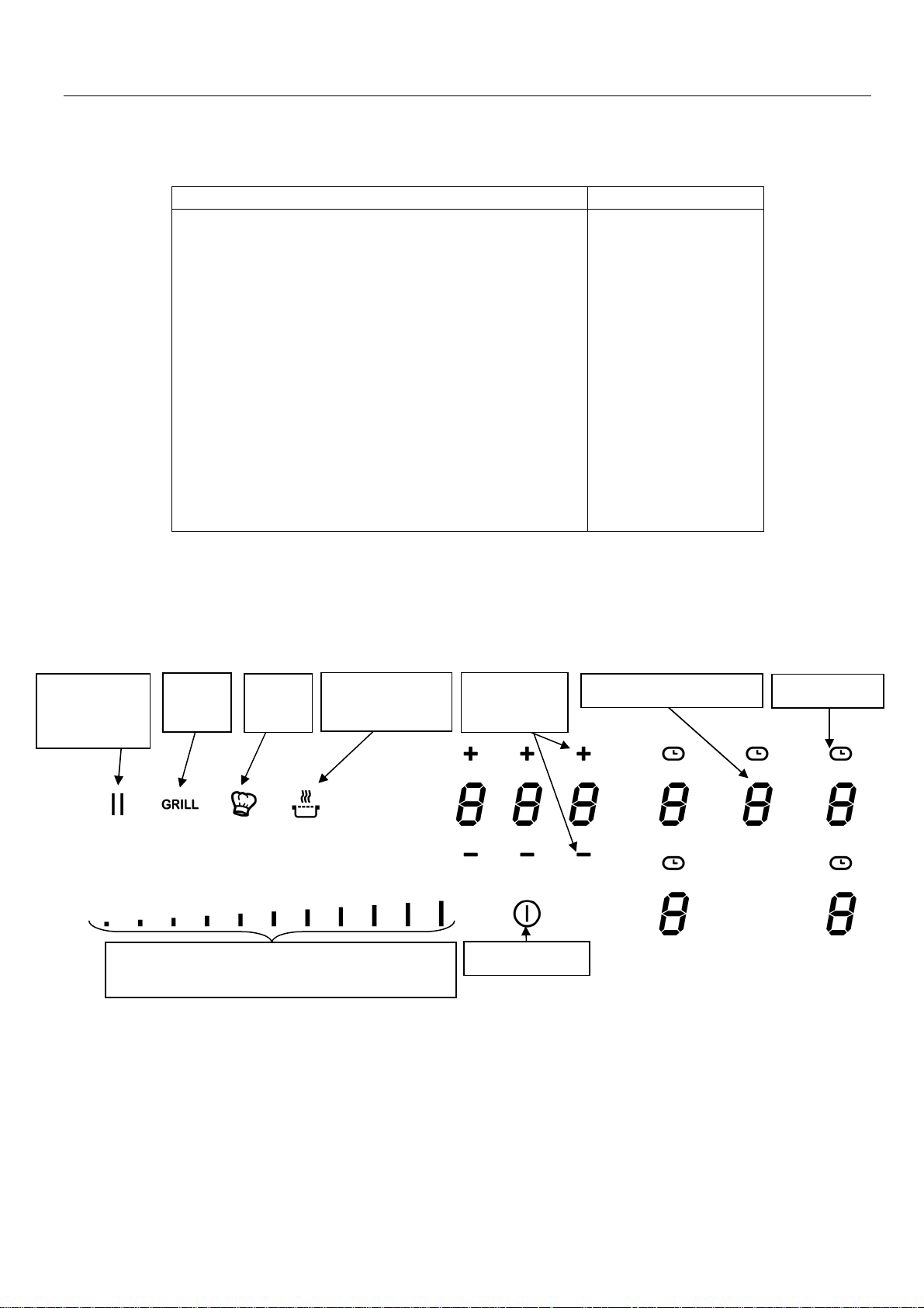
“SLIDER”
AND TIMER SETTING ZONE
........................................................ 9
........................................................................................................ 10
................................................................................. 10
............................................................................................................. 13
.................................................................................. 13
........................................................................................................... 13
........................................................................................................ 14
COOKING ADVICES ................................................................................................................... 17
P
AN QUALITY
P
AN DIMENSION
E
XAMPLES OF COOKING POWER SETTING
............................................................................................................................. 17
.......................................................................................................................... 17
...................................................................................... 18
MAINTENANCE AND CLEANING .............................................................................................. 18
WHAT TO DO IN CASE OF A PROBLEM .................................................................................. 18
ENVIRONMENT PRESERVATION ............................................................................................. 19
INSTALLATION INSTRUCTIONS ............................................................................................... 20
ELECTRICAL CONNECTION ..................................................................................................... 21

SAFETY
Precautions before using
• Unpack all the materials.
• The installation and connecting of the appliance have to be
done by approved specialists. The manufacturer can not be
responsible for damage caused by building-in or connecting
errors.
• To be used, the appliance must be well-equipped and installed
in a kitchen unit and an adapted and approved work surface.
• This domestic appliance is exclusively for the cooking of food,
to the exclusion of any other domestic, commercial or industrial
use.
• Remove all labels and self-adhesives from the ceramic glass.
• Do not change or alter the appliance.
• The cooking plate can not be used as freestanding or as
working surface.
• The appliance must be grounded and connected conforming to
local standards.
• Do not use any extension cable to connect it.
• The appliance can not be used above a dishwasher or a
tumble-dryer: steam may damage the electronic appliances.
• The appliance is not intended to be operated by means of
external timer or separate remote control system.
3

Using the appliance
• Switch the heating zones off after using.
• Keep an eye on the cooking using grease or oils: that may
quickly ignite.
• Be careful not to burn yourself while or after using the
appliance.
• Make sure no cable of any fixed or moving appliance contacts
with the glass or the hot saucepan.
• Magnetically objects (credit cards, floppy disks, calculators)
should not be placed near to the engaged appliance.
• Metallic objects such as knives, forks, spoons and lids should
not be placed on the hob surface since they can get hot.
• In general do not place any metallic object except heating
containers on the glass surface. In case of untimely engaging or
residual heat, this one may heat, melt or even burn.
• Never cover the appliance with a cloth or a protection sheet.
This is supposed to become very hot and catch fire.
• This appliance can be used by children aged from 8 years and
above and persons with reduced physical, sensory or mental
capabilities or lack of experience and knowledge if they have
been given supervision or instruction concerning use of the
appliance in a safe way and understand the hazards involved.
• Children shall not play with the appliance.
• Cleaning and user maintenance shall not be made by children
without supervision.
4

Precautions not to damage the appliance
• Raw pan bottoms or damaged saucepans (not enamelled cast
iron pots,) may damage the ceramic glass.
• Sand or other abrasive materials may damage ceramic glass.
• Avoid dropping objects, even little ones, on the vitroceramic.
• Do not hit the edges of the glass with saucepans.
• Make sure that the ventilation of the appliance works according
to the manufacturer’s instructions.
• Do not put or leave empty saucepans on the vitroceramic hobs.
• Sugar, synthetic materials or aluminium sheets must not
contact with the heating zones. These may cause breaks or
other alterations of the vitroceramic glass by cooling: switch on
the appliance and take them immediately out of the hot heating
zone (be careful: do not burn yourself).
• WARNING: Danger of fire: do not store items on the cooking
surface.
• Never place any hot container over the control panel.
• If a drawer is situated under the embedded appliance, make
sure the space between the content of the drawer and the
inferior part of the appliance is large enough (2 cm). This is
essential to guaranty a correct ventilation.
• Never put any inflammable object (ex. sprays) into the drawer
situated under the vitroceramic hob. The eventual cutlery
drawers must be resistant to heat.
5
Precautions in case of appliance failure
THE HOB AND/OR ITS E
NVIRONMENT.
• If a defect is noticed, switch on the appliance and turn off the
electrical supplying.
• If the ceramic glass is cracked or fissured, you must unplug the
appliance and contact the after sales service.
• Repairing has to be done by specialists. Do not open the
appliance by yourself.
• WARNING: If the surface is cracked, switch off the appliance to
avoid the possibility of electric shock.
Other protections
• Note sure that the container pan is always centred on the
cooking zone. The bottom of the pan must have to cover as
much as possible the cooking zone.
• For the users of pacemaker, the magnetic field could influence
its operating. We recommend getting information to the retailer
or of the doctor.
• Do not to use aluminium or synthetic material containers: they
could melt on still hot cooking zones.
• NEVER try to extinguish a fire with water, but switch off the
appliance and then cover flame e.g. with a lid or a fire blanket.
THE USE OF EITHER POOR QUALITY POT OR ANY
INDUCTION ADAPTOR PLATE FOR NON-MAGNETIC
COOKWARE RESULTS IN A WARRANTY BREACH.
IN THIS CASE, THE MANUFACTURER CANNOT BE
HELD RESPONSIBLE FOR ANY DAMAGE CAUSED TO
6
DESCRIPTION OF THE APPLIANCE
Type
P906IM3G5NE
Total power
11100 W
Energy consumption for the hob EC
** 188 Wh/kg
Front left h
eating zone
21
0 x 190 mm
Minimum detecti
on Ø 100 mm
Nominal
level
* 2100 W
Booster
level
* 2600 W
Double booster
level
* 3700 W
Cookware
**
Ø 150 mm
(x2)
Energy consumption EC
** 182.8 Wh/kg
Cookware
**
Ø 180 mm (x2)
Energy consumption EC
** 190.6 Wh/kg
Cookware
**
Ø 210 mm (x
2)
Energy consumption EC
** 188.1 Wh/kg
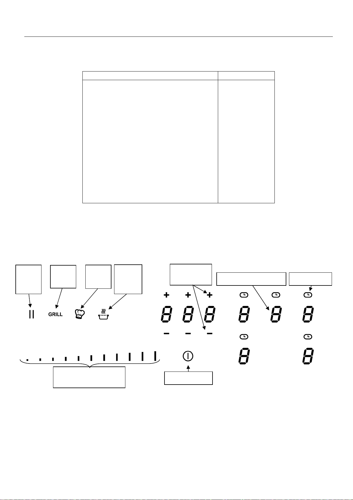
“
Slider
”
Time
r key
and [
- ] key
key
key
On / Off key
Selection zone key
Technical characteristics
hob
cw
cw
cw
* The given power may change according to the dimensions and material of the pan.
**Calculated according to the method of measuring performance (EN 60350-2).
Control panel
Pause/
Recal
Grill
key
Power selection zone
Chef
key
Keep
warm
Timer [ + ]
7

USE OF THE APPLIANCE
Display
Display Designation Description
0 Zero The heating zone is activated.
1…9 Booster level Selection of the cooking level.
U No pan detection No pan or inadequate pan.
A Heat accelerator Automatic cooking.
E Error message Electronic failure.
H Residual heat The heating zone is hot.
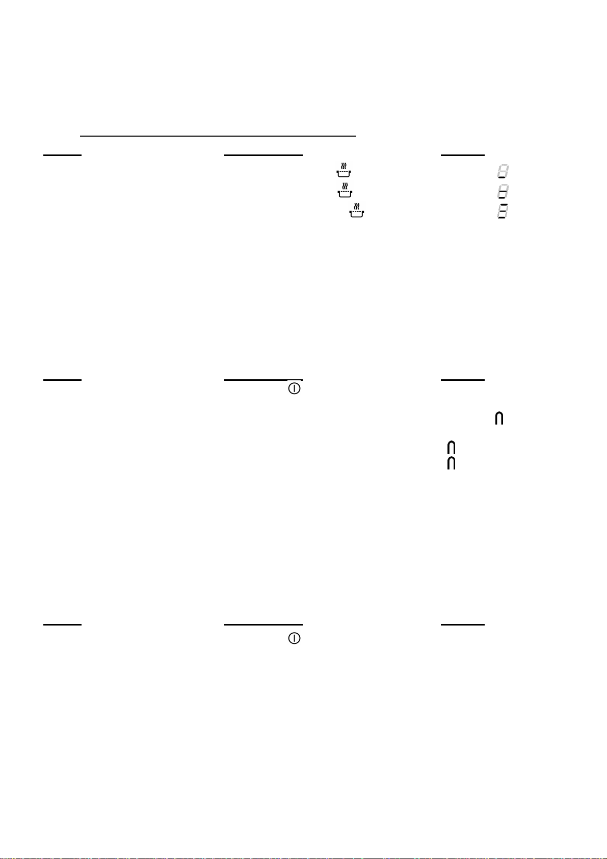
P Power The Power is activated.
Super Power The Super power is activated.
U Keep warm Maintain automatically of 42, 70 or 94°C.
Keep warm Maintain automatically of 70°C.
Keep warm Maintain automatically of 90°C.
II Stop&Go The hob is in pause.
∏ Bridge 2 cooking zones are combined.
Keep warm Maintain automatically of 42°C.
Ventilation
The cooling system is fully automatic. The cooling fan starts with a low speed when the calories
brought out by the electronic system reach a certain level. The ventilation starts his high speed
when the hob is intensively used. The cooling fan reduces his speed and stops automatically
when the electronic circuit is cooled enough.
STARTING-UP AND APPLIANCE MANAGEMENT
Before the first use
Clean your hob with a damp cloth, and then dry the surface thoroughly. Do not use detergent
which risks causing blue-tinted colour on the glass surface.
Induction principle
An induction coil is located under each heating zone. When it is engaged, it produces a variable
electromagnetic field which produces inductive currents in the ferromagnetic bottom plate of the
pan. The result is a heating-up of the pan located on the heating zone.
Of course the pan has to be adapted:
• All ferromagnetic pans are recommended (please verify it thanks a little magnet): cast iron
and steel pans, enamelled pans, stainless-steel pans with ferromagnetic bottoms…
• Are excluded: cupper, pure stainless-steel, aluminium, glass, wood, ceramic, stoneware,…
The induction heating zone adapts automatically the size of the pan. With a too small diameter
the pan doesn’t work. This diameter is varying in function of the heating zone diameter.
If the pan is not adapted to the induction hob the display will show [ U ].
8
Sensitive touch
“SLIDER“
Direct access
Your ceramic hob is equipped with electronic controls with sensitive touch keys. When your finger
presses the key, the corresponding command is activated. This activation is validated by a
control light, a letter or a number in the display and/or a “beep” sound.
In the case of a general use press only one key at the same time.
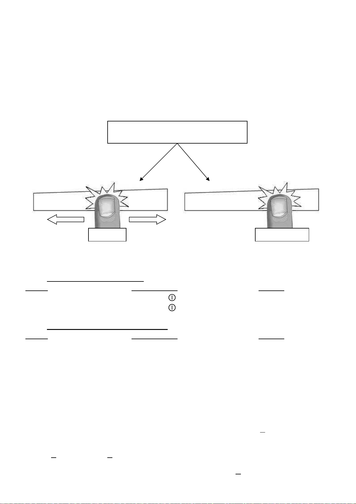
Power selection zone “SLIDER” and timer setting zone
To select the power with the slider, slide your finger on the “SLIDER” zone. You can already have
a direct access if you put your finger directly on the chosen level.
Power selection zone “SLIDER” and
timer setting zone
Starting-up
• Start up / switch off the hob:
Action Control panel Display
To start press key [ ] for 2 sec. [ 0 ]
To stop press key [ ] for 2 sec. nothing or [ H ]
• Start up / switch off a heating zone:
Action Control panel Display
To set slide on the “SLIDER“ [ 1 ] to [ P ]
(adjust the power) to the right or to the left
To stop slide to [ 0 ] on “SLIDER“ [ 0 ] or [ H ]
If no action is made within 20 second the electronics returns in waiting position.
Pan detection
The pan detection ensures a perfect safety. The induction doesn’t work:
• If there is no pan on the heating zone or if this pan is not adapted to the induction. In this
case it is impossible to increase the power and the display shows [ U ]. This symbol
disappears when a pan is put on the heating zone.
• If the pan is removed from the heating zone the operation is stopped. The display shows
[ U ]. The symbol [ U ] disappears when the pan is put back to the heating zone. The
cooking continues with the power level set before.
After use, switch the heat element off: don’t let the pan detection [ U ] active.
9
Residual heat indication
After the switch off of a heating zone or the complete stop of the hob, the heating zones are still
hot and indicates [ H ] on the display.
The symbol [ H ] disappears when the heating zones may be touched without danger.
As far as the residual heat indicators are on light, don’t touch the heating zones and don’t put any
heat sensitive object on them. There are risks of burn and fire.
Booster and double booster function
Power [ P ] and Super Power [ ] grant a boost of Power to the selected heating zone.
If this function is activated the heating zones work during 10 minutes with an ultra high Power.
This is foreseen for example to heat up rapidly big quantities of water, like nuddles
• Start up / Stop the booster:
Action Control panel Display
Start up the booster Slide to the end of the “SLIDER” [ P ]
Or press directly on the end of
the “SLIDER”
Stop the booster Slide on the “SLIDER“ [ 9 ] to [ 0 ]
• Start up / Stop double booster
Action Control panel Display
Start up the booster Slide to the end of the “SLIDER” [ P ]
Or press directly on the end of
the “SLIDER”
Start up double booster Re-press key [ P ] [ and P ]
Stop the double booster Slide on the “SLIDER“ [ P ] to [ 0 ]
Stop booster Slide on the “SLIDER“ [ 9 ] to [ 0 ]
• Power management:
The table is divided in 3 separate sets of heating zones, each set having a maximum power.
If the selected heating levels for both zones exceed the maximum available amount of power,
the power management function is automatically reducing the power from one of these zones.
The display of this zone is first blinking; the level is then automatically reduced to the highest
suitable position.
Heating zone selected The other heating zone: (example: power level 9)
[ P ] is displayed [ 9 ] goes to [ 8 ] and blinks
It is possible to activate the booster function (or double booster) on several cooking zones at
the same time, for this it is necessary to use the zones in a discriminant way (A-B, A-C, B-C or
A-B-C).
10

Timer
The timer is able to be used simultaneous with all heating zones and this with different time
settings (from 0 to 1H59 minutes) for each heating zone.
• Setting and modification of the cooking time:
Action Control panel Display
Select a zone Press a zone [ 0 ]
Select the power level slide on the “SLIDER“ [ 1 ] to [ P ]
Select theTimer Press key [ ] Timer display on
Decrease the time Press key [ - ] from the timer [ 60 ] to 59, 58...
Increase the time Press key [ + ] from the timer Time increase
After a few seconds, the [ ] display stops with blinking.
The time is confirmed and the timer starts.
• To stop the cooking time:
Action Control panel Display
Select the Timer Press key [ ] Timer display on
Stop the time Press key [ - ] from the timer [ 000 ]
If several timers are activated, repeat the process.
• Egg timer function:
Egg timer is an independent function. It stops as soon as a heating zone starts up.
If the egg timer is on and the hob is switched off, the timer continues until time runs out.
Action Control panel Display
Activate the hob Press key [ ] for 2 sec. [ 0 ]
Select the Timer Press [ 000 ] [ 000 ]
Decrease the time Press key [ - ] from the timer [ 60 ] to 59, 58...
Increase the time Press key [ + ] from the timer Time increase
After a few seconds, the [ min ] display stops with blinking.
The time is confirmed and the timer starts.
• Automatic stop at the end of the cooking time:
As soon as the selected cooking time is finished the timer displays blinking [ 000 ] and a sound
rings.
To stop the sound and the blinking, press the key [ - ] and [ + ].
11
Automatic cooking
1 0:40
2 1:12
3 2:00
4 2:56
5 4:16
6 7:12
7 2:00
8 3:12
9 - : -
All the cooking zones are equipped with an automatic cooking device. The cooking zone starts at
full power during a certain time, and then reduces automatically its power on the pre-selected
level.
• Start-up:
Action Control panel Display
Power level selection slide on the “SLIDER“ to [ 7 ] [ 7 ] is blinking with [ A ]
(for example « 7 ») and stay 3s
Selected power
• Switching off the automatic cooking:
Action Control panel Display
Power level selection slide on the “SLIDER“ [ 0 ] to [ 9 ]
Automatic cooking
time (Min:S)
Stop&Go function
This function brakes all the hob’s cooking activity temporarily and allows restarting with the same
settings.
• Start up/stop the pause function:
Action Control panel Display
Engage pause press [ II ] 2s [ II ] and control light on
Stop the pause press [ II ] 2s previous settings
Recall Function
After switching off the hob ( ), it is possible to recall the last settings.
• cooking stages of all cooking zones (Booster)
• minutes and seconds of programmed cooking zone-related timers
• Keep warm function
• Automatic cooking
The recall procedure is following:
• Press the key [ ] for 2 sec.
• Then press [ II ] before the light stops blinking.
The previous settings are again active.
12
“Keep warm” Function
This function allows the reach and automatically maintains at the temperature of 42, 70 or 94°C.
This will avoid liquids overflowing and fast burning at the bottom of the pan.
• To engage, to start the function « Keep warm »:
Action Control panel Display
42°C to engage Press once on key [
70°C to engage Press twice on key [ ] [ U ] and [ ]
94°C to engage Press 3 times on key [ ] [ U ] and [ ]
To stop Slide on the “SLIDER“ [ 0 ] to [ 9 ]
The maximum duration of keeping warm is 2 hours.
] [ U ] and [ ]
Bridge or Automatic Bridge Function
This function allows the use of 2 cooking zones at the same time with the same features as a
single cooking zone. With this function the Booster function is allowed on the left and center
zones.
Action Control panel Display
Activate the hob Press key [ ] for 2 sec. [ 0 ]
Activate the bridge Manually: press simultaneously
of the 2 cooking zones [ 0 ] and [ ]
or
Automatically: put a great pan on the [ ] blink
2 zones and press on the 2 “SLIDER” [ ]
Increase bridge Slide on the “SLIDER“
witch indicates the power [ 1 ] to [ 9 ]
Stop the bridge Press simultaneously
of the 2 cooking zones [ 0 ]
Control panel locking
To avoid modification of the setting of the cooking zones , in particular during cleaning, the
control panel can be locked (with exception to the On/Off key [ 0/I ]).
Action Control panel Display
Activate the hob Press key [ ] for 2 sec. [ 0 ]
Locking the hob Hold for 3s the key of an area then [ L ]
press the "Slider" which scrolls and
swipe from left to right
Unlock the hob Hold for 3s the key of an area then [ 0 ] ou [ H ]
press the "Slider" which scrolls and
swipe from left to right
13
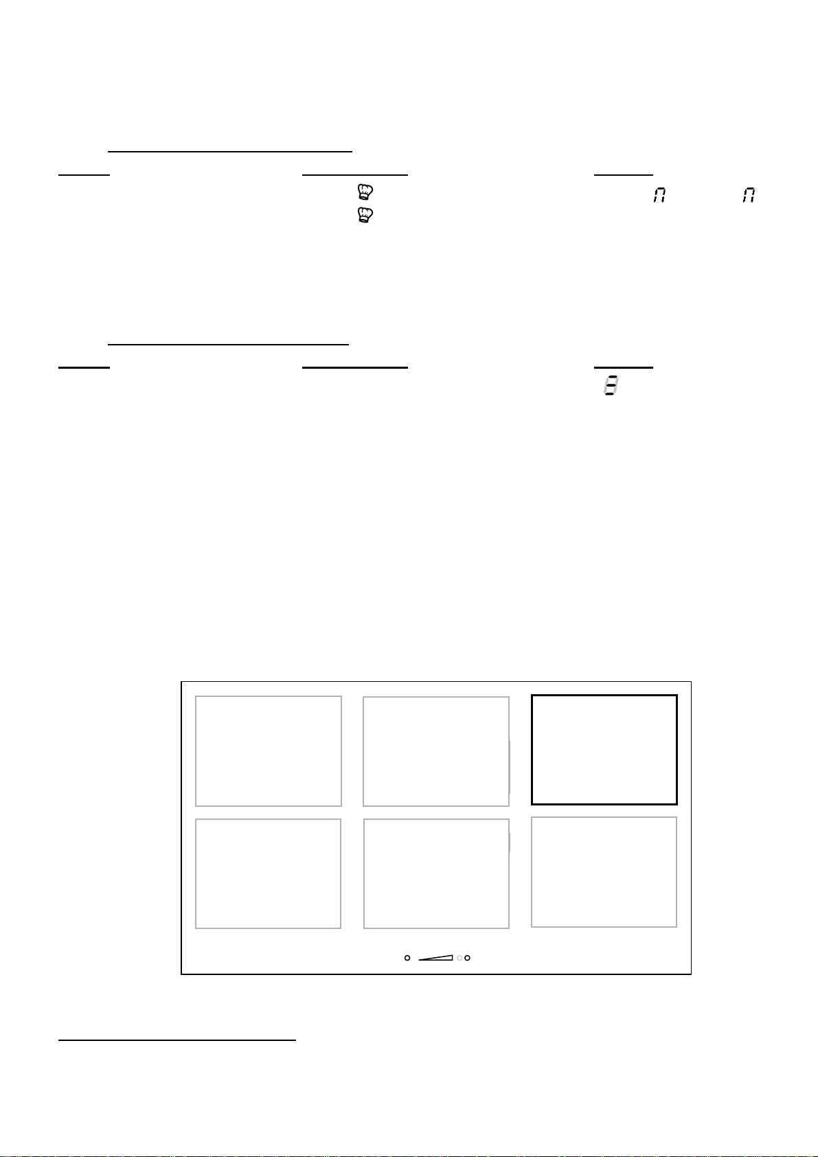
“Chef“ function
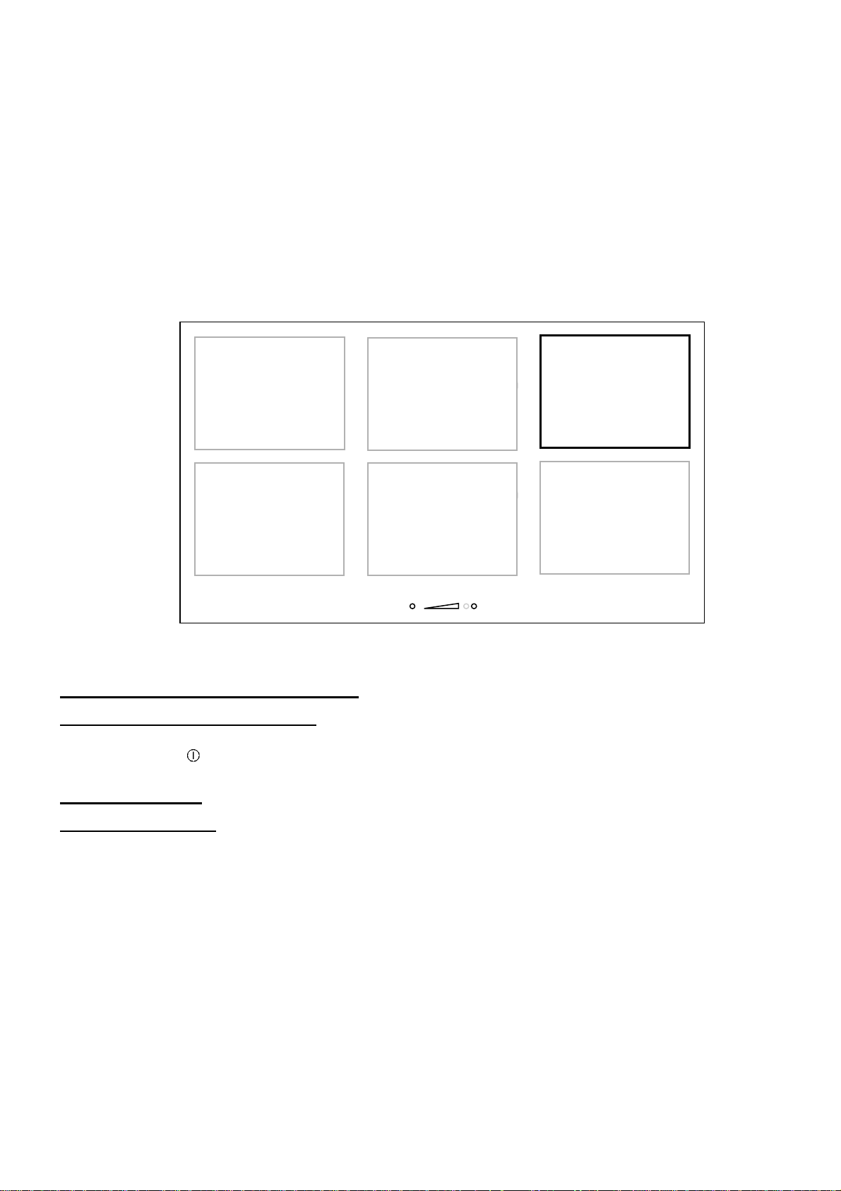
Test zone
This function changes the hob in 2 big zones.
• Start up/stop the chef function:
Action Control panel Display
Engage the chef function press [ ] [ 3 ] et [ ], [ 9 ] et [ ]
Stop the chef function press [ ] [ 0 ]
Grill function
This function allows the optimal use of the grill plate with combining two areas and using
appropriate powers.
• Start up/stop the grill function:
Action Control panel Display
Engage the grill function press [ GRILL ] [ ]
Stop the grill function press [ GRILL ] [ 0 ]
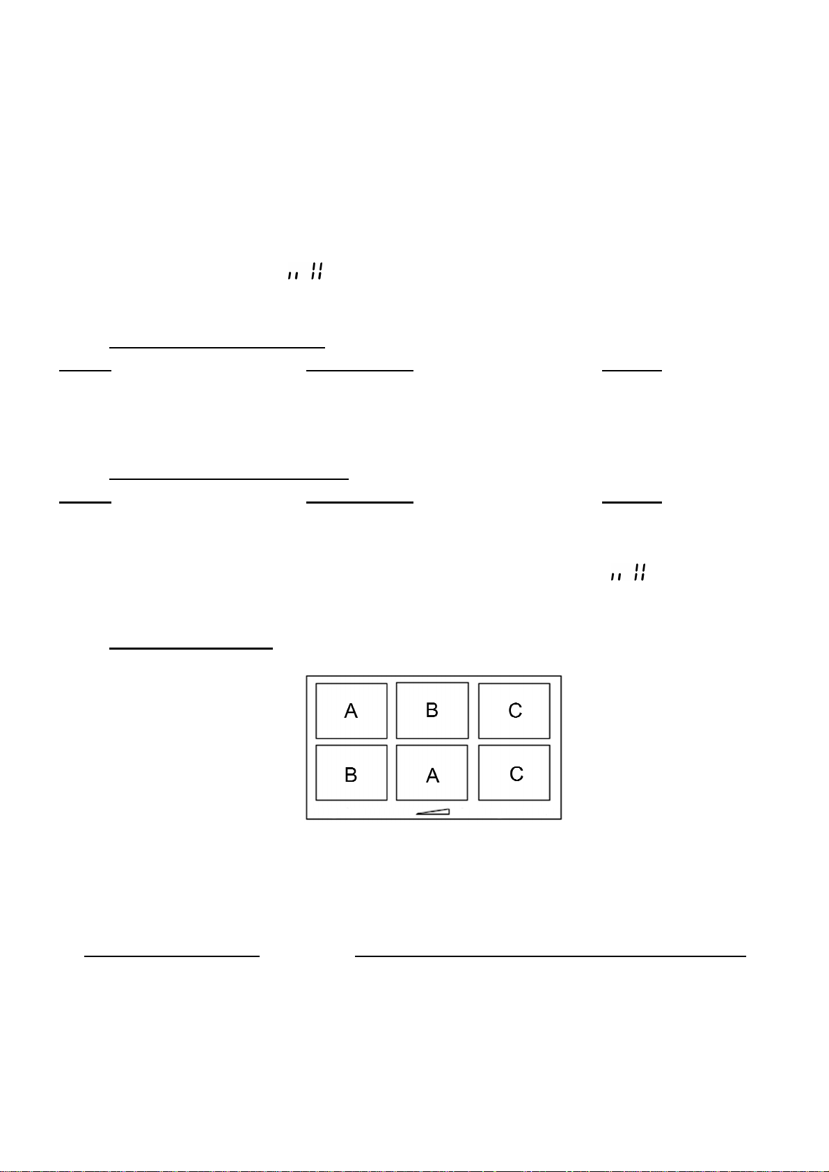
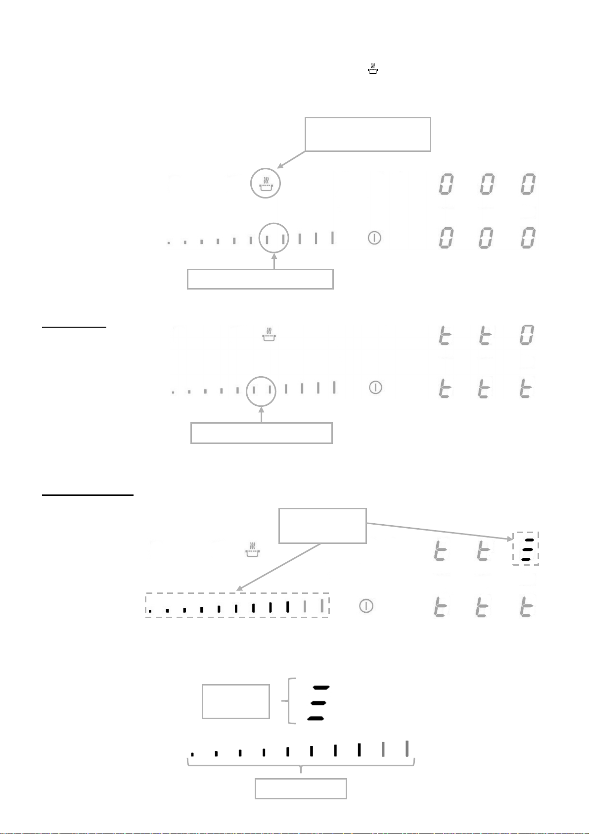
Pot Speed Test function
With induction technology the cookware is an important part of the cooking system.
As a part of the cooking system, you should make sure that the cookware you are using, offers
the best cooking experience by giving back the high performance level of our induction hob.
The Pot speed Test function offers the possibility to measure the efficiency and the heating rate
of your cookware.
The test can only be performed when there is no current cooking operation and only on the zone
specified below.
Each action has to be done in the 6 seconds after the previous one.
Put the cookware on test zone
14
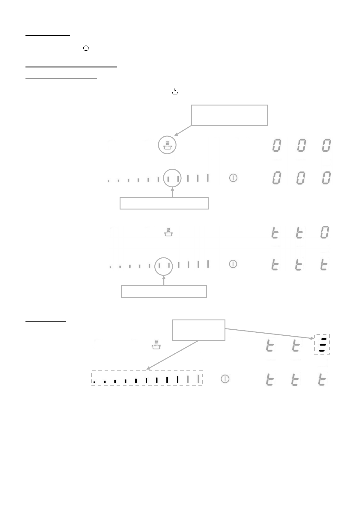
Start the hob
warm key
Press on the
“SLIDER”
Press on/off key [ ]
In the 6 seconds after start
Activate the function
Press simultaneously on the keep warm key [ ] and on the “SLIDER”.
[ 0 ], [ t ] are displayed.
[ 0 ] is fixed.
Press on the keep
[ t ] is blinking.
Start the test
Press on the “SLIDER”.
[ 0 ] is moving.
[ t ] is blinking.
Test results
Test results
15
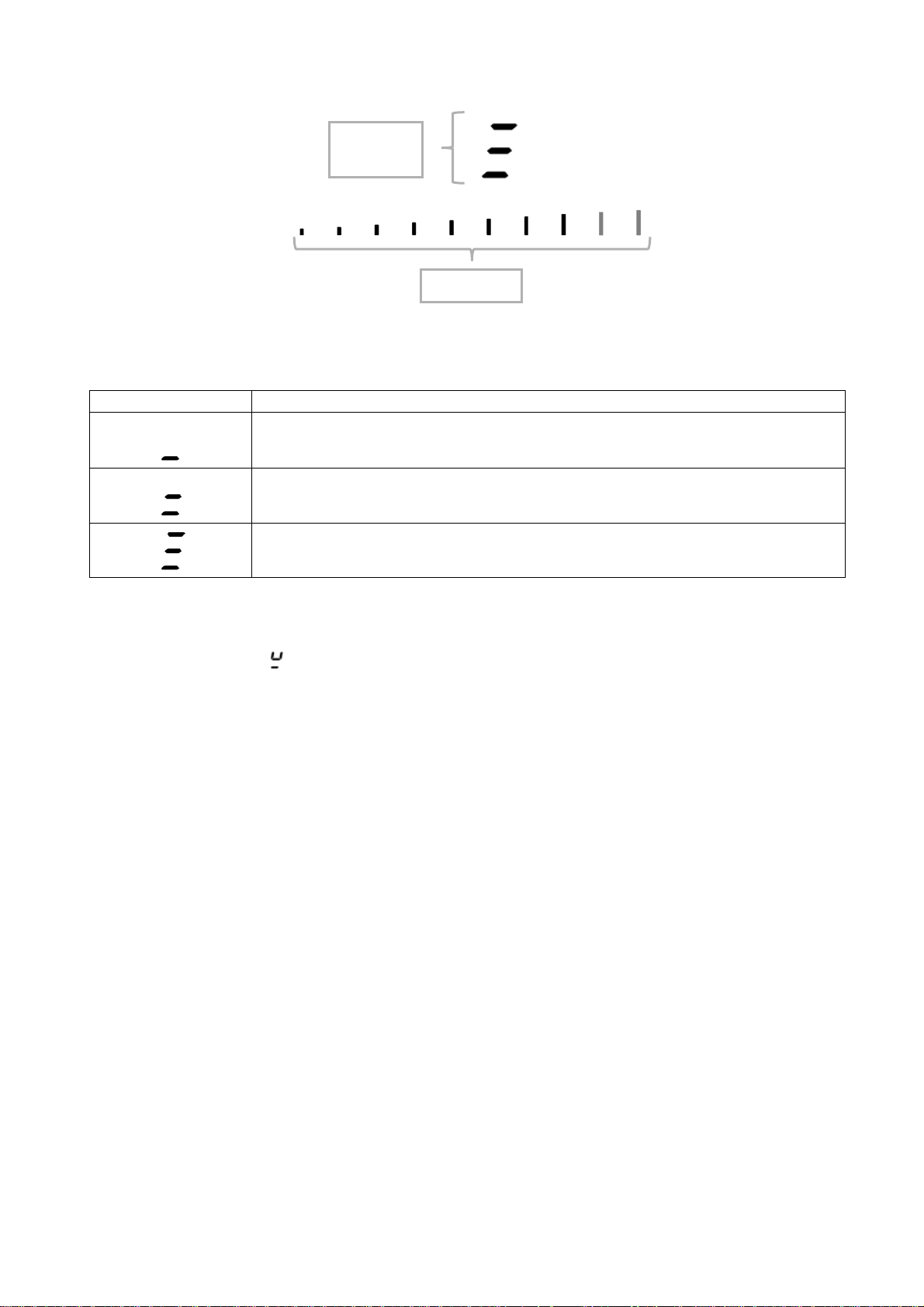
For example, the cookware speed level 7:
Category symbol
Indication
category
Speed
Speed
The cookware is classified in one of these 3 categories, with refined speed level displayed on the
bar graph.
Low speed performance, the cookware is not recommended for
induction cooking.
Medium speed performance, the cookware is adapted for induction
cooking.
High performance cookware for the best induction cooking experience.
Important advises:
Some cookware could have such low efficiency that they are even not detected by the hob,
in this case the symbol [ ] will be displayed.
The cookware should always be centered in the test zone, an improper centering may cause
inaccurate results.
The results are displayed for 3 seconds, after this time the hob switches automatically in normal
mode and can be used for cooking.
Note that the speed level is not the only important point assessing the quality of the cookware
and to make sure that is perfectly adapted for induction please refers to the “Cooking advices”
chapter for more details.
16
COOKING ADVICES
Pan quality
Adapted materials: steel, enamelled steel, cast iron, ferromagnetic stainless-steel,
aluminium with ferromagnetic bottom.
Not adapted materials: aluminium and stainless-steel without ferromagnetic bottom,
cupper, brass, glass, ceramic, porcelain.
The manufacturers specify if their products are compatible induction.
To check if pans are compatibles:
• Put a little water in a pan placed on an induction heating zone set at level [ 9 ].This water
must heat in a few seconds.
• A magnet stucks on the bottom of the pan.
Certain pans can make noise when they are placed on an induction cooking zone. This noise
doesn’t mean any failure on the appliance and doesn’t influence the cooking operating.
The composition of the pan base can affect the evenness of the cooking results and power
reception by the inductors.
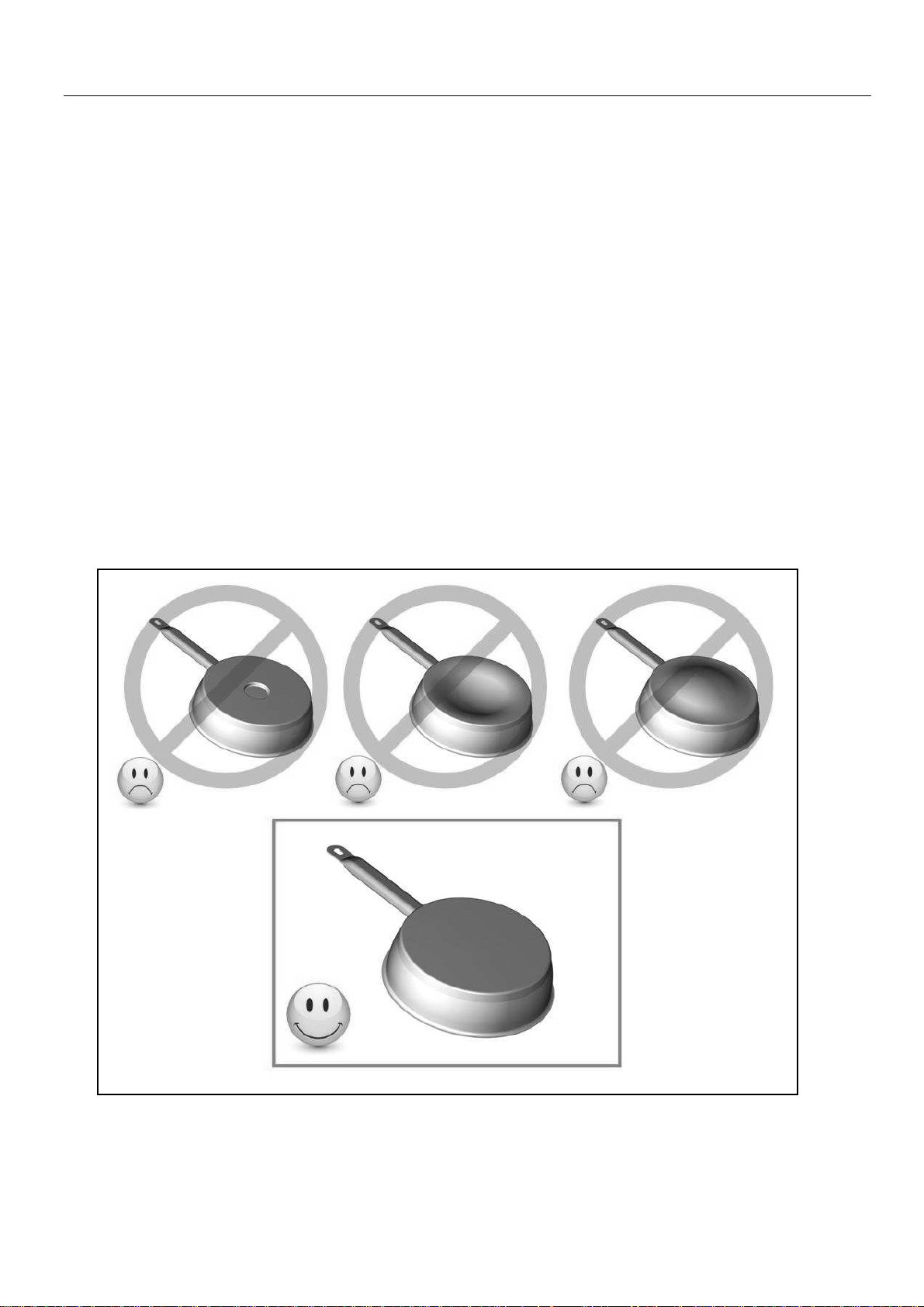
Only use pots and pans with smooth bases. Rough bases will scratch the ceramic glass.
Where possible, use pans with vertically straight side. If a pan has angular sides, induction also
acts on the side of the pan. The sides of the pan may discolour.
Pan dimension
The cooking zones are, until a certain limit, automatically adapted to the diameter of the pan.
However the bottom of this pan must have a minimum of diameter according to the
corresponding cooking zone.
To obtain the best efficiency of your hob, please place the pan well in the centre of the cooking
zone.
17
Examples of cooking power setting
Reheating
Dishes prepared beforehand
Defrosting
Dried vegetables, fish, frozen products
3 to 4
Steam
Vegetables, fish, meat
fresh vegetables
Simmering
Goulash, roulade, tripe
7 to 8
Cooking
Potatoes, fritters, wafers
Boiling water
Water
Boil
ing water
Boiling significant quantities of water
(the values below are indicative)
1 to 2 Melting
Sauces, butter, chocolate, gelatine
2 to 3 Simmering
4 to 5 Water Steamed potatoes, soups, pasta,
6 to 7 Medium cooking
9 Frying, roosting
P and
Frying, roosting
Rice, pudding, sugar syrup
Meat, lever, eggs, sausages
Steaks, omelettes, fried dishes
scallops, steaks
MAINTENANCE AND CLEANING
Switch-off the appliance before cleaning.
Do not clean the hob if the glass is too hot because they are risk of burn.
• Remove light marks with a damp cloth with washing up liquid diluted in a little water. Then
rinse with cold water and dry the surface thoroughly.
• Highly corrosive or abrasive detergents and cleaning equipment likely to cause scratches
must be absolutely avoided.
• Do not ever use any steam-cleaner or pressure washer
• Do not use any object that may scratch the ceramic glass.
• Ensure that the pan is dry and clean. Ensure that there are no grains of dust on your
ceramic hob or on the pan. Sliding rough saucepans will scratch the surface.
• Spillages of sugar, jam, jelly, etc. must be removed immediately. You will thus prevent the
surface being damaged.
WHAT TO DO IN CASE OF A PROBLEM
The hob or the cooking zone doesn’t start-up:
• The hob is badly connected on the electrical network.
• The protection fuse cut-off.
• The looking function is activated.
• The sensitive keys are covered of grease or water.
• An object is put on a key.
The control panel displays [ U ]:
• There is no pan on the cooking zone.
• The pan is not compatible with induction.
• The bottom diameter of the pan is too small.
18
The control panel displays [ E ]:
the household appliances.
• The electronic system is defective.
• Disconnect and replug the hob.
• Call after sales
One or all cooking zone cut-off:
• The safety system functioned.
• You forgot to cut-off the cooking zone for a long time.
• One or more sensitive keys are covered.
• The pan is empty and its bottom overheated.
• The hob also has an automatic reduction of Booster level and breaking Automatic
overheating
Continuous ventilation after cutting off the hob:
• This is not a failure, the fan continuous to protect the electronic device.
• The fan cooling stops automatically.
The automatic cooking system doesn’t start-up:
• The cooking zone is still hot [ H ].
• The highest Booster level is set [ 9 ].
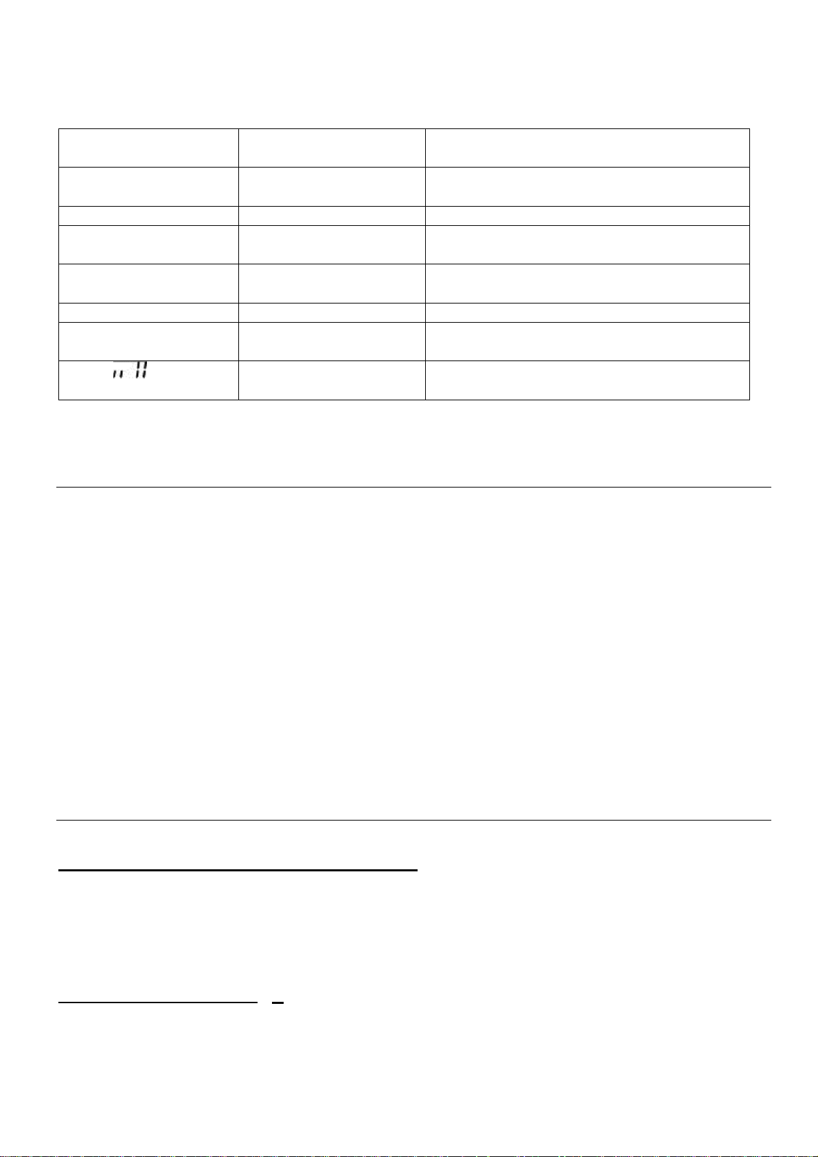
The control panel displays [ U ]:
• Refer to the chapter “Keep warm“.
The control panel displays [ II ]:
• Refer to the chapter “Stop&Go“
The control panel displays [ ] or [ Er03 ] :
• An object or liquid covers the control keys. The symbol disappear as soon as the key is
released or cleaned.
The control panel displays [ E2 ] :
• The hob is overheated, let it cool and then turn it on again.
The control panel displays [ E8 ] :
• The air inlet of the ventilator is obstructed, release it.
The control panel displays [ U400 ] :
• The hob is not connected to the network. Check the connection and reconnect the hob.
The control panel displays [ Er47 ] :
• The hob is not connected to the network. Check the connection and reconnect the hob.
If one of the symbols above persists, call the SAV.
ENVIRONMENT PRESERVATION
• The materials of packing are ecological and recyclable.
• The electronic appliances are composed of recyclable, and sometimes harmful materials
for the environment, but necessary to the good running and the safety of the appliance.
• Don't throw your appliance with the household refuses
• Get in touch with the waste collection centre of your
commune that is adapted to the recycling of
19
INSTALLATION INSTRUCTIONS
, after removing
The installation comes under the exclusive responsibility of specialists.
The installer is held to respect the legislation and the standards enforce in his home country.
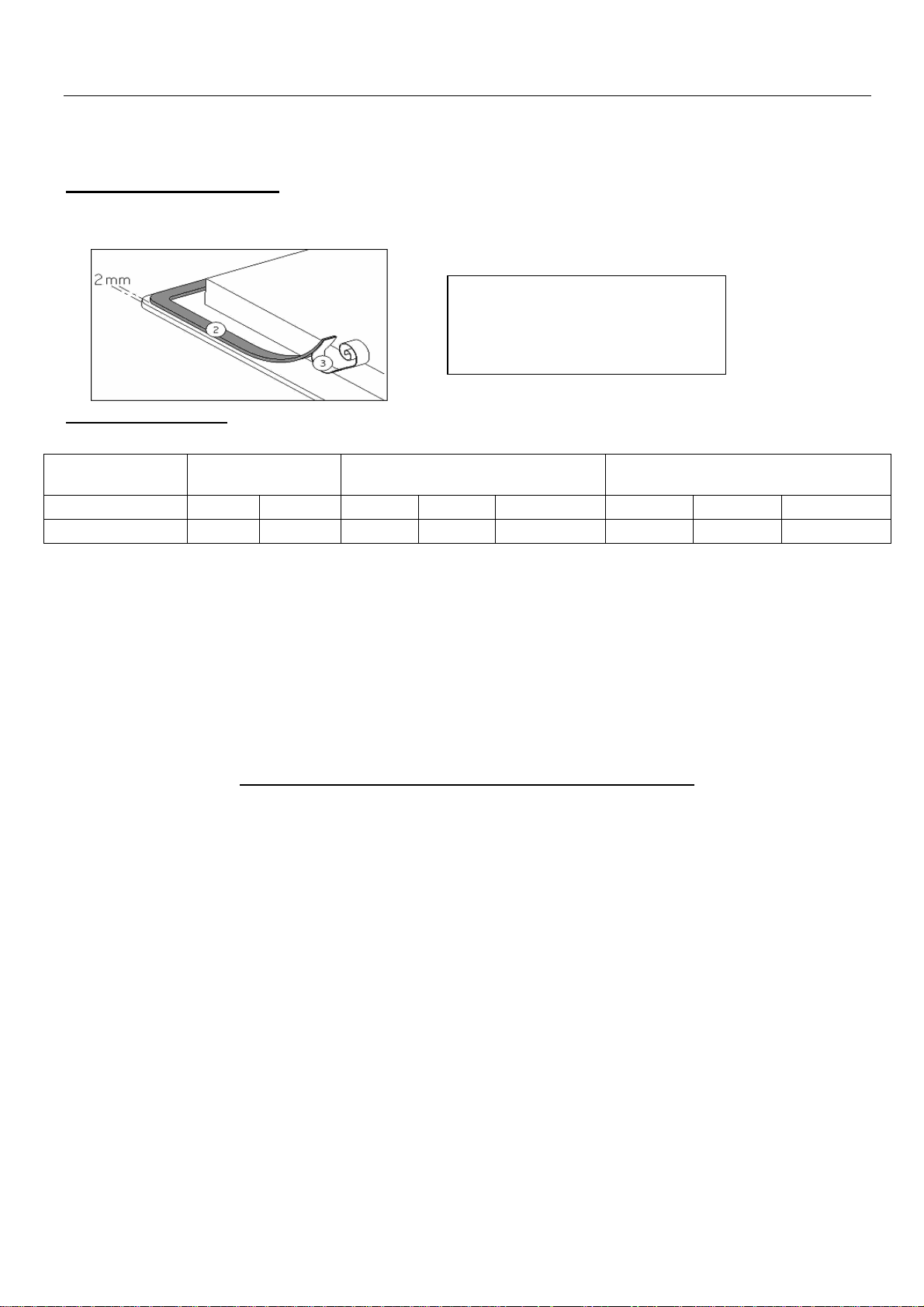
How to stick the gasket:
The gasket supplied with the hob avoids all infiltration of liquids in the cabinet.
His installation has to be done carefully, in conformity of the following drawing.
Fitting - installing:
• The cut out sizes are:
Type Cut size Cut size of flush mouting Glass size
Width Depth Width Depth Radius Width Depth Thickness
P906IM3G5NE 750
490
886 526 8 880 520 4
• Ensure that there is a distance of 50 mm between the hob and the wall or sides.
• The hobs are classified as “Y” class for heat protection. Ideally the hob should be installed
with plenty of space on either side. There may be a wall at the rear and tall units or a wall
at one side. On the other side, however, no unit or divider must stand higher than
the hob.
• The piece of furniture or the support in which the hob is to be fitted, as well as the edges of
furniture, the laminate coatings and the glue used to fix them, must be able to resist
temperatures of up to 100 °C.
• The mural rods of edge must be heat-resisting.
• Not to install the hob to the top of a not ventilated oven or a dishwasher.
• To guarantee under the bottom of the hob casing a space of 20 mm to ensure a good air
circulation of the electronic device.
• If a drawer is placed under the work, avoid to put into this drawer flammable objects
(for example: sprays) or not heat-resistant objects.
• Materials which are often used to make worktops expand on contact with water. To protect
the cut out edge, apply a coat of varnish or special sealant. Particular care must be given
to applying the adhesive joint supplied with the hob to prevent any leakage into the
supporting furniture. This gasket guaranties a correct seal when used in conjunction with
smooth work top surfaces.
• The safety gap between the hob and the cooker hood placed above must respect the
indications of the hood manufacturer. In case of absence of instructions respect a distance
minimum of 760 mm.
• The connection cord should be subjected, after building, with no mechanical constraint,
such for example of the fact of the drawer.
• WARNING: Use only hob guards designed by the manufacturer of the cooking appliance
or indicated by the manufacturer of the appliance in the instructions for use as suitable or
hob guards incorporated in the appliance. The use of inappropriate guards can cause
accidents.
Stick the gasket (2) two
millimeters from the external
edge of the glass
the protection sheet (3).
20

ELECTRICAL CONNECTION
• The installation of this appliance and the connection to the electrical network should be
entrusted only to an electrician perfectly to the fact of the normative regulations and which
respects them scrupulously.
• Protection against the parts under tension must be ensured after the building-in.
• The data of connection necessary are on the stickers place on the hob casing near the
connection box.
• The connection to the main must be made using an earthed plug or via an omnipolar
circuit breaking device with a contact opening of at least 3 mm.
• The electrical circuit must be separated from the network by adapted devices, for example:
circuit breakers, fuses or contactors.
• If the appliance is not fitted with an accessible plug, disconnecting means must be
incorporated in the fixed installation, in accordance with the installation regulations.
• The inlet hose must be positioned so that it does not touch any of the hot parts of the hob
or oven.
Caution!
This appliance has only to be connected to a network 230 V~ 50/60 Hz.
Connect always the earth wire.
Respect the connection diagram.
The connection box is located underneath at the back of the hob casing. To open the cover use a
medium screwdriver. Place it in the slits and open the cover.
CONNECTION OF THE HOB:
Mains Connection Supply cord Supply cord Circuit braker
230 V~ 50/60 Hz 1 phase +N 3 x 4 mm2
400 V~ 50/60Hz 2 phases + N
400 V~ 50/60Hz 3 phases + N 5 x 1,5 mm2
* calculated with the simultaneous factor following the standard EN 60 335-2-6
4 x 2,5 mm2
H 05 VV - F
H 05 RR - F
H 05 VV - F
H 05 RR - F
H 05 VV - F
H 05 RR - F
40 A *
25 A *
16 A *
21

For the various kinds of connection, use the brass bridges which are in the box next the terminal
equipped with a faulty earth connection.
Monophase 230V~1P+N
Put the 1st bridge between terminal 1, 2 and 3, the 2nd between 4 and 5.
Attach the earth to the terminal “earth”, the neutral N to terminal 4 or 5, the Phase L to one of the
terminals 1, 2 or 3.
Biphase 400V~2P+N
Put the 1st bridge between terminal 1 and 2, the 2nd between 4 and 5.
Attach the earth to the terminal “earth”, the neutral N to terminal 4 or 5, the Phase L1 to the
terminals 1 or 2 and the Phase L2 to the terminal 3.
Triphase 400V~3P+N
Put a bridge between terminal 4 and 5.
Attach the earth to the terminal “earth”, the neutral N to terminal 4 or 5, the Phase L1 to the
terminals 1 and the Phase L2 to the terminal 2 and the Phase L3 to the terminal 3.
Caution! Be careful that the cables are correctly engaged and tightened.
We cannot be held responsible for any incident resulting from incorrect connection or
which could arise from the use of an appliance which has not been earthed or has been
22

INDICE
SICUREZZA ................................................................................................................................ 24
P
RECAUZIONI PRIMA DEL PRIMO UTILIZZO
I
STRUZIONI DI SICUREZZA
P
RECAUZIONI ONDE NON DANNEGGIARE L’APPARECCHIO
P
RECAUZIONI IN CASO DI MALFUNZIONAMENTO DELL’APPARECCHIO
A
LTRE PRECAUZIONI
............................................................................................................ 25
................................................................................................................... 27
DESCRIZIONE DELL’APPARECCHIO ....................................................................................... 28
D
ATI TECNICI
P
ANNELLO DI CONTROLLO
.............................................................................................................................. 28
........................................................................................................... 28
USO DELL’APPARECCHIO ....................................................................................................... 29
I
NDICAZIONI
V
ENTILAZIONE
............................................................................................................................... 29
............................................................................................................................ 29
PRIMA ACCENSIONE E UTILIZZO DELL’APPARECCHIO ...................................................... 29
P
RIMA DEL PRIMO UTILIZZO
P
RINCIPIO DELL’INDUZIONE
L
E FUNZIONI DEI SENSORI
"SLIDER"
A
CCENDERE E SPEGNERE IL PIANO DI COTTURA
R
ICONOSCIMENTO DEL RECIPIENTE DI COTTURA
I
NDICATORE CALORE RESIDUO
F
UNZIONE BOOSTER
T
IMER
C
OTTURA AUTOMATICA
F
UNZIONE STOP&GO
F
UNZIONE RECALL
F
UNZIONE SCALDAVIVANDE
F
UNZIONE BRIDGE O BRIDGE AUTOMATICA
B
LOCCO DEL PANNELLO DI CONTROLLO
F
UNZIONE “CHEF
F
UNZIONE GRILL
F
UNZIONE POT SPEED TEST
PER LA ZONA SELEZIONATA
................................................................................................................... 31
....................................................................................................................................... 32
..................................................................................................................... 34
” ...................................................................................................................... 35
........................................................................................................................ 35
.......................................................................................................... 29
.......................................................................................................... 29
............................................................................................................ 30
..................................................................................................... 31
............................................................................................................... 33
................................................................................................................. 33
......................................................................................................... 34
....................................................................................................... 36
..................................................................................... 24
............................................................... 26
................................................ 27
......................................................................................... 30
............................................................................ 30
............................................................................ 31
................................................................................... 34
........................................................................................ 35
CONSIGLI PER LA COTTURA ................................................................................................... 39
R
ECIPIENTI DI COTTURA
D
IMENSIONI RECIPIENTI DI COTTURA
E
SEMPI DI REGOLAZIONE DELLA POTENZA
.............................................................................................................. 39
............................................................................................. 39
..................................................................................... 40
MANUTENZIONE E PULIZIA ...................................................................................................... 40
IN CASO DI ANOMALIE ............................................................................................................. 40
TUTELA AMBIENTALE .............................................................................................................. 41
ISTRUZIONI DI INSTALLAZIONE .............................................................................................. 42
CONNESSIONE ELETTRICA ..................................................................................................... 43
23

SICUREZZA
Precauzioni prima del primo utilizzo
•
Sballare eliminando tutti i materiali di imballo.
•
L’installazione e connessione dell’apparecchio devono essere
effettuate da personale specializzato. Il fabbricante declina ogni
responsabilità civile e penale per danni causati da installazione
e/o connessione non realizzate a regola d’arte. Per essere
utilizzato, l’apparecchio deve essere correttamente installato in
una cucina e su una superficie di lavoro idonea.
•
Per essere utilizzato, l’apparecchio deve essere correttamente
installato in una cucina e su una superficie di lavoro idonea
attenendosi naturalmente alle disposizioni di sicurezza vigenti
in materia.
•
Questo elettrodomestico è progettato esclusivamente per la
cottura di cibo, con l’espressa esclusione di ogni altro uso
domestico, commerciale o industriale.
•
Rimuovere tutte le etichette adesive dal vetro.
•
Non apportare alcuna modifica o alterazione all’apparecchio.
•
La superficie in vetro dell’apparecchio non può essere utilizzata
come zona di appoggio o di lavoro.
•
L’apparecchio deve essere opportunamente messo a terra e
collegato alla rete elettrica secondo la normativa in vigore
localmente.
•
Non usare nessuna prolunga elettrica per collegare il cavo di
alimentazione.
•
L’apparecchio non può essere utilizzato sopra una lavastoviglie
o una asciugatrice: il vapore potrebbe danneggiare i
componenti elettronici dell’apparecchio.
•
Questo apparecchio non è da utilizzare con un timer esterno o
un telecomando separato.
24

Istruzioni di sicurezza
•
La parte elettronica (relais) può provocare durante l‘esercizio
rumori udibili di attivazione. Può essere percepibile anche la
ventola di raffreddamento. La ventola di raffreddamento può
continuare a girare anche dopo la fine del processo di cottura
per raffreddare i componenti elettronici. Ciò non significa che il
piano ad induzione sia difettoso o che funzioni in modo
anomalo e il piano di cottura funziona senza problemi.
•
Spegnere le zone di cottura dopo l’uso.
•
Grassi ed olii surriscaldati prendono facilmente fuoco.
Controllare le cotture che utilizzano grasso o olio: potrebbero
incendiarsi con facilità.
•
Le zone di cottura si riscaldano durante la cottura. Fare
attenzione a non ustionarsi durante o dopo l’uso
dell’apparecchio.
•
Verificare che nessun cablaggio di apparecchi fissi o mobili
venga in contatto con il vetro dell’apparecchio o con pentole
bollenti.
•
Gli oggetti magnetici (carte di credito, floppy discs, calcolatrici)
non devono essere piazzati vicino all’apparecchio quando
questo è acceso. Questi oggetti potrebbero danneggiarsi.
•
Gli oggetti metallici quali coltelli, forchette, cucchiai e coperchi
non devono essere piazzati sull’apparecchio perché potrebbero
diventare incandescenti.
•
Gli oggetti metallici quali cucchiai e coperchi non devono essere
piazzati sull’apparecchio ad induzione perché potrebbero
diventare incandescenti.
•
Non coprire mai l’apparecchio con un panno o telo protettivo,
perché potrebbe surriscaldarsi e bruciare.
•
Questo apparecchio può essere usato da bambini con una età
minima di otto anni e da persone le cui capacità fisiche,
sensoriali o mentali sono ridotte, o le cui esperienze e
conoscenze sono inadatte, unicamente se sotto sorveglianza e
dietro formazione sull’uso dell’apparecchio, in condizioni di
sicurezza e dopo essere state informate sui rischi in cui
potrebbero incorrere.
•
I bambini non devono giocare con l’apparecchio.
25

•
La pulizia e la manutenzione non possono essere affidate a
bambini senza la sorveglianza di un adulto.
Precauzioni onde non danneggiare l’apparecchio
•
Pentole con fondo graffiato o danneggiato possono
danneggiare il vetro ceramico. Le pentole potrebbero graffiare
la superficie in vetroceramica.
•
Sabbia o altre sostanze abrasive possono danneggiare il vetro
ceramico.
•
Il vetro ceramico non è sensibile agli shock termici ed è molto
resistente, non è tuttavia infrangibile. Evitare di far cadere
oggetti, anche piccoli, sul vetro ceramico.
•
Non colpire i bordi del vetro con le pentole.
•
Non mettere o lasciare pentole vuote sul vetro ceramico.
•
Lo zucchero, i materiali sintetici e i fogli di alluminio non devono
venire a contatto con le zone riscaldante, perché possono
causare rotture o altre alterazioni del vetro ceramico durante il
raffreddamento. Nel caso, accendere immediatamente
l’apparecchio e rimuovere l’oggetto dalla zona di cottura,
prendendo le opportune precauzioni per non ustionarsi.
•
Pericolo di incendio! Non appoggiare alcun oggetto sul piano di
cottura.
•
Non piazzare mai un contenitore bollente sul pannello di
controllo. L'elettronica sotto il vetro potrebbe danneggiarsi.
•
Se sotto il piano cottura incassato c’è un cassetto, assicurarsi
che lo spazio tra il contenuto dello stesso e la parte inferiore
dell’apparecchio sia sufficiente (almeno 2 cm) per evitare
contatti accidentali.
•
Non mettere mai oggetti infiammabili (ad es. spray) nel cassetto
situato sotto l’apparecchio. Gli eventuali contenitori per posate
posti in cassetti sotto l’apparecchio devono essere resistenti al
calore.
•
Non riscaldare contenitori chiusi (per es. barattoli di conserve)
sulle zone cottura. A causa della conseguente sovrappressione
i contenitori e/o i barattoli possono scoppiare, e sussiste il
pericolo di lesioni!
26

Precauzioni in caso di malfunzionamento dell’apparecchio
DI COTTURA O DANNI CORRELATI.
•
Se si nota un difetto di funzionamento, spegnere l’apparecchio
e disconnetterlo dalla rete elettrica.
•
Se il vetro ceramico è rotto o crepato: disconnettere
immediatamente l’apparecchio dalla rete elettrica, svitando e
rimuovendo il fusibile e chiamare l’assistenza tecnica.
•
Qualsiasi riparazione deve essere compiuta esclusivamente da
personale qualificato.
•
ATTENZIONE! Se la superficie del vetro è crepata o rotta,
spegnere immediatamente l’apparecchio per evitare il rischio di
scosse elettriche.
Altre precauzioni
•
Assicurarsi che la pentola o padella sia sempre centrata sulla
zona di cottura. Il fondo dell’utensile deve coprire il più possibile
la zona di cottura.
•
Per gli utilizzatori di pace-makers: il campo magnetico
dell’apparecchio potrebbe influenzare il funzionamento del
pace-maker. Si raccomanda di richiedere preventivamente
informazioni al venditore dell’apparecchio e/o al medico
curante.
•
Non utilizzare contenitori di alluminio o di materiali sintetici!
Potrebbero fondere se appoggiati alle zone accese o ancora
calde dopo l’uso.
•
Non utilizzare mai acqua per spegnere il fuoco. Disattivare la
zona di cottura. Soffocare le fiamme con un coperchio, una
coperta ignifuga o qualcosa di simile.
L’UTILIZZO DI PENTOLE NON IDONEE OPPURE DI
ACCESSORI RIMUOVIBILI POSTI TRA LA PENTOLA E
LA PIASTRA PER RISCALDARE PENTOLE NON
IDONEE ALL’INDUZIONE FA DECADERE LA
GARANZIA.
IL COSTRUTTORE NON PUÒ ESSERE CONSIDERATO
RESPONSABILE PER QUALSIASI DANNO AL PIANO
27
DESCRIZIONE DELL’APPARECCHIO
Typo
P906IM3G5NE
Potenza totale
11100 W
Consumo d
i energia del piano cottura EC
** 188 Wh/kg
Zona di cottura
21
0 x 190 mm
Identificazione minimo
Ø 100 mm
Potenza nominale
*
2100 W
Potenza booster
*
2600 W
Potenza doppio
booster*
3700 W
Categoria standard di pentola **
Ø 150 mm
(x2)
Consumo
di energia EC
** 182.8 Wh/kg
Categoria standard di pentola **
Ø 180 mm (x2)
Consumo di energia EC
** 190.6 Wh/kg
Categoria standard di pentola **
Ø 210 mm (x2)
Consumo di energia EC
** 188.1 Wh/kg
selezionata
Tasto On / Off
Richiama
Tasto selezione zona
Tasto timer
Dati tecnici
hob
cw
cw
cw
* La Potenza dichiarata può cambiare a seconda delle dimensioni e del material della pentola.
** metodo di misura delle prestazioni secondo la norma (EN60350-2)
Pannello di controllo
Tasto
Pausa/
Tasto
Grill
Tasto
Chef
“Slider” per regolazione potenza zona
Tasto
Scaldavivande
Tasto timer
[ + ] e [ - ]
28

USO DELL’APPARECCHIO
Indicazioni
Indicazione Definizione Descrizione
0 zero zona di cottura attivata
1 … 9 gradazioni impostazione livello potenza
U recipiente non rilevato manca recipiente o non adatto
A cottura iniziale automatica potenza massima + cottura preliminare
E indicazione guasto anomalia dei dispositivi elettronici
H calore residuo la zona di cottura è ancora calda
P booster funzione booster attivata
doppio booster doppio booster attivato
mantenere al caldo le pietanze vengono mantenute
al caldo a 42°C
mantenere al caldo le pietanze vengono mantenute
al caldo a 70 °C
mantenere al caldo le pietanze vengono mantenute
al caldo a 94°C
II Pausa il piano di cottura è in pausa
Ventilazione
La ventola si attiva automaticamente. Si avvia a bassa velocità appena i valori dei dispositivi
elettronici superano una determinata soglia. Quando il piano ad induzione viene usato
intensamente, la ventola funziona ad alta velocità. La ventola funziona più lentamente appena i
dispositivi elettronici si sono sufficientemente raffreddati.
PRIMA ACCENSIONE E UTILIZZO DELL’APPARECCHIO
Prima del primo utilizzo
Pulire l’apparecchio con uno straccio umido, indi asciugarlo accuratamente. Non utilizzare
detergenti che possano causare colorazioni anomale del vetro.
Principio dell’induzione
Sotto ogni piastra riscaldante si trova un magnete induttore. Quanto viene attivato, questo
produce un campo elettromagnetico che genera una corrente induttiva nel fondo ferromagnetico
della pentola. Il risultato è il riscaldamento della pentola posizionata sulla piastra.
Naturalmente, la pentola deve essere adatta:
• Tutte le pentole in materiale ferromagnetico sono consigliate (verificare utilizzando una
calamita): pentole in ghisa, acciaio, smaltate e di acciaio inossidabile con fondo
ferromagnetico…
• Da escludere: pentole in rame, acciaio inossidabile senza fondo ferromagnetico, alluminio,
vetro, legno, ceramica, terracotta…
La piastra a induzione si adatta automaticamente alla dimensione della pentola: se il diametro di
quest’ultima è troppo piccolo tuttavia, la piastra non funziona. Il diametro minimo varia in funzione
del diametro della piastra.
Se la pentola non è adatta al piano di cottura a induzione, il display mostrerà la lettera [ U ].
29

Le funzioni dei sensori
Il piano di cottura viene comandato con sensori che reagiscono sfiorando il vetro col dito. Se si
sfiorano i sensori per un secondo circa, le funzioni selezionate si attivano. Ogni reazione dei
sensori viene confermata da un segnale acustico e/o visivo.
Per gli usi convenzionali, sfiorare un sensore alla volta.
"SLIDER" per la zona selezionata
Per selezionare la potenza con lo "SLIDER" basta spostare il dito sulla zona di scorrimento
„SLIDER“. Per selezionare direttamente la gradazione basta sfiorare col dito il sensore della
gradazione desiderata.
„SLIDER“
„SLIDER“ per la zona
selezionata
selezione
diretta
Accendere e spegnere il piano di cottura
Accendere prima il piano di cottura e successivamente la zona di cottura desiderata.
• Accendere / spegnere il piano di cottura
operazione sensore di comando indicazione
accendere premere [ ] per 2 s. [ 0 ]
spegnere premere [ ] per 2 s. nessuna o [ H ]
• Accendere / spegnere la zona di cottura
operazione sensore di comando indicazione
aumentare la potenza scorrere sullo "SLIDER" da [ 1 ] a [ P ]
spegnere scorrere sullo "SLIDER" fino a [ 0 ] [ 0 ] o [ H ]
Se non si effettuato altre impostazioni, per motivi di sicurezza il piano di cottura si spegne
automaticamente dopo 20 secondi unitamente all’indicazione.
30

Riconoscimento del recipiente di cottura
Il dispositivo di riconoscimento del recipiente di cottura garantisce una sicurezza completa.
• L’induzione non funziona se sulla zona di cottura non si trova una pentola o se la
pentola non è adatta per l’induzione. In questi casi non è possibile aumentare la
gradazione e nell’indicatore viene visualizzato il simbolo [ U ]. Il simbolo [ U ] si spegne
se sulla zona di cottura si pone il recipiente di cottura.
• Se durante la cottura si toglie il recipiente dalla zona di cottura, la zona di cottura si
spegne subito e nell'indicatore appare il simbolo [ U ]. Appena si colloca il recipiente di
cottura sulla zona, il simbolo [ U ] si spegne e la zona di cottura si attiva nuovamente
con la gradazione precedentemente impostata.
A cottura ultimata, spegnere la zona di cottura per evitare che venga visualizzato il simbolo [ U ].
Indicatore calore residuo
Dopo aver spento la zona di cottura o il piano di cottura, per le zone di cottura ancora calde viene
visualizzato il simbolo [ H ] per il calore residuo. Il simbolo [ H ] si spegne quando si possono
toccare le zone di cottura senza scottarsi. Fintanto che il simbolo del calore residuo rimane
visualizzato, evitare di toccare le zone calde e di mettervi oggetti non resistenti al calore. Pericolo
di ustionarsi!
Funzione Booster
Tutte le zone di cottura sono dotate di funzioni booster e doppio booster, ossia con una potenza
maggiorata. La funzione booster viene visualizzata col simbolo [ P ]; la funzione doppio booster
con [ P ] e inoltre con [ ] lampeggiante.
Se le funzioni booster sono attivate, le zone di cottura interessate si riscaldano per 10 minuti con
una potenza maggiorata. Tale funzione potenziata è pratica per portare ad ebollizione in poco
tempo una notevole quantità d’acqua per cuocere, ad esempio, la pasta.
• Attivare / disattivare la funzione booster
operazione sensore di comando indicazione
attivare booster scorrere sullo "SLIDER" fino alla fine [ P ]
o premere subito alla fine
disattivare booster scorrere sullo "SLIDER" da [ 9 ] a [ 0 ]
• Attivare / disattivare doppio booster
operazione sensore di comando indicazione
attivare booster scorrere sullo "SLIDER" fino alla fine [ P ]
o premere subito alla fine
attivare doppio booster premere di nuovo fine sullo lampeggia con [P]
"SLIDER" [ ]
disattivare doppio booster scorrere sullo "SLIDER" da [ P ] a [ 0 ]
disattivare booster scorrere sullo "SLIDER" da [ 9 ] a [ 0 ]
31

• Regolazione automatica della funzione booster
Il piano di cottura è dotato di una potenza complessiva. Per non superare questa potenza limite, i
dispositivi elettronici riducono automaticamente la potenza di un’altra zona di cottura quando
viene attivata la funzione booster. La potenza ridotta di questa zona di cottura viene visualizzata
con [ 9 ] lampeggiante.
Zona di cottura selezionata altra zona di cottura (ad es. con potenza 9)
[ P ] acceso [ 9 ] ridotto a [ 6 ] oppure a [ 8 ] e lampeggiante
È possibile attivare contemporaneamente la funzione di ricarica in più zone, per cui è necessario
utilizzare zone di diverse unità (A-B, A-C, B-C o A-B-C).
Timer
Con il timer integrato si può impostare per tutte le quattro zone una durata di cottura da 1 a 1H59
minuti. Per ogni zona di cottura è possibile impostare una durata diversa.
• Impostazione e regolazione del tempo di cottura:
Azione Pannello di controllo Display
Selezionare una zona Premere su una zona [ 0 ]
Impostare il livello di potenza Scorrere il cursore “SLIDER“
verso destra da [ 1 ] a [ P ]
Selezionare il timer Premere tasto [ ] Display timer acceso
Diminuire il tempo Premere tasto [ - ] del timer da [ 60 ] a 59, 58...
Aumentare il tempo Premere tasto [ + ] del timer Incremento del tempo
Dopo alcuni secondi il simbolo [ ] smette di lampeggiare.
La durata viene confermata e il timer parte.
• Arresto del tempo di cottura:
Azione Pannello di controllo Display
Selezionare il tempo Premere tasto [ ] Display timer acceso
Arrestare il tempo Premere tasto [ - ] del timer [ 000 ]
Nel caso fossero attivi diversi timer, ripetere la procedura.
• Funzione timer uovo:
Il timer dell’uovo è una funzione indipendente. Il timer si arresta non appena una zona di
riscaldamento viene avviata.
Se il timer dell’uovo è acceso e il piano di cottura è spento, il timer prosegue fino allo scadere del
tempo.
32

Azione Pannello di controllo Display
1 0:40
2 1:12
3 2:00
4 2:56
5 4:16
6 7:12
7 2:00
8 3:12
9 - : -
Attivare il piano di cottura Premere display [ ] per 2 s. [ 0 ]
Selezionare il timer Premere [ 000 ] [ 000 ]
Diminuire il tempo Premere tasto [ - ] del timer [ 60 ] to 59, 58...
Aumentare il tempo Premere tasto [ + ] del timer Incremento del tempo
Dopo alcuni secondi, il display [ min ] smette di lampeggiare.
La durata viene confermata e il timer parte.
• Arresto automatico al termine del tempo di cottura:
Non appena il tempo di cottura impostato termina, il timer visualizza [ 000 ] lampeggiante ed emette
un segnale sonoro.
Per interrompere il segnale sonoro e il lampeggiamento, premere i tasti [ - ] e [ + ].
Cottura automatica
Tutte le zone di cottura sono dotate di un dispositivo di cottura automatica. La zona di cottura
parte a piena potenza per un certo periodo di tempo, poi riduce automaticamente la potenza al
livello preimpostato.
• Avvio:
Azione Pannello di controllo Display
Impostazione livello potenza Portare il cursore “SLIDER“ su [ 7 ] [ 7 ] lampeggia con [ A ]
(ad esempio « 7 ») e mantenere per 3s
Livello di cottura di
proseguimento impostato
• Disattivate la cottura automatica:
Azione Pannello di controllo Display
Impostazione livello potenza Alzare il cursore “SLIDER“ da [ 0 ] a [ 9 ]
Cottura con avvio
rapidoTempo (min:sec)
Funzione Stop&Go
Questa funzione arresta temporaneamente tutta l’attività di cottura del piano di cottura e
consente di ripartire con le stesse impostazioni.
• Avvio/arresto della funzione pausa:
Azione Pannello di controllo Display
Attivare la pausa premere [ II ] per 2s [ II ] e spia accesi
Disattiva la pausa premere [ II ] per 2s impostazioni precedenti
33

Funzione Recall
Dopo aver spento il fornello ( ), è possibile richiamare le ultime impostazioni.
• Stadi di cottura di tutte le zone di cottura (Booster)
• Minuti e secondi di timer di cottura programmata per ogni zona
• Funzione di mantenimento in caldo (“Keep warm”)
• Cottura automatica
La procedura di Recall è la seguente:
• Premere il tasto [ ] per 2 s.
• Quindi premere [ II ] prima che la spia smetta di lampeggiare.
Le impostazioni precedenti sono nuovamente attive.
Funzione Scaldavivande
Questa funzione consente di mantenere il cibo a una temperatura costante di 42, 70 o 94°C.
Si evitano così fuoriuscite di liquido e bruciatura rapida sul fondo della pentola/padella.
• Per attivare la funzione “Keep warm”:
Azione Pannello di controllo Display
Per attivare a 42°C Premere una volta il tasto [ ] [ U ] e [ ]
Per attivare a 70°C Premere due volte il tasto [
Per attivare a 94°C Premere tre volte il tasto [
Per disattivare Far scorrere il cursore “SLIDER“ da [ 0 ] a [ 9 ]
o premere il tasto [Keep warm] fino a [ 0 ] [ 0 ]
La durata massima del mantenimento in caldo è 2 ore.
] [ U ] e [ ]
] [ U ] e [ ]
Funzione Bridge o Bridge automatica
Questa funzione consente di regolare contemporaneamente 2 zone di cottura impostando
un’unica zona. Questa funzione consente di attivare la funzione Booster sulla zona di sinistra e
centrale.
Azione Pannello di controllo Display
Attivare il piano di cottura Premere display [ ] per 2 s. [ 0 ]
Attivare la funzione Bridge Premere contemporaneamente
delle due zone di cottura [ 0 ] e [ ]
oppure
appoggiare una padella grande su 2 zone [ ] lampeggiante
e premere i 2 cursori “SLIDER” [ ]
Aumentare il ponte Aumentare i due cursori “SLIDER“
che indicano la potenza da [ 1 ] a [ 9 ]
Arrestare il ponte Premere contemporaneamente
delle due zone di cottura [ 0 ]
34

Blocco del pannello di controllo
Per evitare di modificare le impostazioni delle zone di cottura, soprattutto durante la pulizia, il
pannello di controllo può essere bloccato (con la sola eccezione del tasto On/Off [ 0/I ]).
Azione Pannello di controllo Display
Attivare il piano di cottura Premere tasto [ ] per 2 s. [ 0 ]
Bloccare il piano di cottura Tenere premuto per 3s il tasto di [ L ]
un’area, quindi premere lo "Slider" e
scorrere da sinistra a destra
Sbloccare il piano di cottura Tenere premuto per 3s il tasto di [ 0 ] o [ H ]
un’area, quindi premere lo "Slider" e
scorrere da sinistra a destra
Funzione “Chef”
Questa funzione suddivide il piano cottura in 2 grandi zone.
• Attivare/Disattivare la funzione chef:
Azione Pannello di controllo Display
Attivare la funzione Chef Premere [ ] [ 3 ] e [ ], [ 9 ] e [ ]
Disattivare la funzione Chef Premere [ ] [ 0 ]
Funzione Grill
Questa funzione permette l'ottimale utilizzo della piastra grill interconnettendo due zone e
l'utilizzo di adeguati livello di potenza.
• Attivare/Disattivare la funzione grill:
Azione Pannello di controllo Display
Attivare la funzione Grill Premere [ GRILL ] [ ]
Disattivare la funzione Grill Premere [ GRILL ] [ 0 ]
35
Funzione Pot Speed Test
La Padella è un componente importante di un sistema di induzione. È necessario fare in modo
che la padella si utilizza offre la migliore esperienza, consentendo di sfruttare al massimo le
capacità del vostro piano di cottura a induzione.
La funzione Pot Test consente di misurare l'efficacia e la velocità di cottura della vostra padella.
Questo test può essere fatto solo quando non ci sono operazioni di cottura in corso, e solo sulla
zona specificato.
Ogni Operazione deve essere completato entro 6s dopo il precedente.
Mettete la padella sulla zona di prova
Foyer de
test
Accensione del piano di cottura
Premere on/off [ ]
In 6s dopo l'avvio
Attivare la funzione
36
di velocità
livello di velocità
mantenimento al caldo
test
Premere contemporaneamente tasto mantenimento al caldo [ ] e sul “SLIDER”.
[ 0 ], [ t ] fisso.
[ 0 ] fissa.
[ t ] lampeggiano.
Premere tasto
Inizia il test
Premere il “SLIDER”.
[ 0 ] è in movimento.
[ t ] lampeggiano.
Risultati del test
Risultati del
Ad esempio, una padella con un risultato livello di velocità 7 :
Categorie
37

Simboli
Indicazione
La padella è classificato in una di queste tre categorie, e il suo livello di velocità precisa è
impostato utilizzando il grafico a barre.
Basso livello di velocità, questo padella non è raccomandato per
cottura a induzione.
Livello di velocità media, questa padella è adatto per cottura a
induzione.
Alto livello di velocità, questo padella offre la migliore esperienza di
cottura a induzione.
Suggerimenti importanti :
Alcune padella possono avere un cattivo compatibilità e non sono nemmeno riconosciuti dal
tavolo.
In questo caso, il display visualizza il simbolo [ ] .
La padella deve essere sempre centrata sulla zona di prova, altrimenti il risultato potrebbe essere
falso.
Il risultato viene visualizzato per 3 secondi, dopo il piano di cottura passa automaticamente alla
modalità normale, e lo si può utilizzare per la cottura.
Si noti che il livello di velocità non è l'unico criterio importante per giudicare la qualità della vostra
padella e assicurarsi che sia perfettamente compatibile con il piano di cottura. Per maggiori
dettagli, si rimanda al capitolo "Consigli di cucina"
38

CONSIGLI PER LA COTTURA
Recipienti di cottura
Materiali adatti: acciaio, acciaio smaltato, ghisa, acciaio con fondo magnetizzabile,
alluminio con fondo magnetizzabile
Materiali non adatti: alluminio e acciaio con fondo non magnetizzabile, rame, ottone, coccio,
porcellana
In via di massima, i fabbricanti indicano se i recipienti di cottura sono adatti per i piani ad induzione.
Per verificare se i recipienti di cottura sono indicati per il piano ad induzione.
• Versare nella pentola un po’ d’acqua e collocarlo sulla zona di cottura ad induzione. Accendere
la zona e selezionare la gradazione [ 9 ]. L’acqua deve riscaldarsi in pochi secondi.
• Toccare con una calamita il fondo della pentola. Se la calamita rimane attaccata, la
pentola è indicata per il piano ad induzione.
Alcuni recipienti possono generare rumori se vengono posti su una zona di cottura ad induzione.
Ciò non significa che il piano ad induzione sia difettoso o che funzioni in modo anomalo.
Le pentole devono essere certificate dal fabbricante come compatibili con l’induzione.
E’ tuttavia possibile che certe pentole, seppur dichiarate come compatibili, abbiano in
realtà caratteristiche inadatte all’uso con i piani a induzione.
Raccomandiamo di verificare al momento dell’acquisto che le pentole rispettino almeno le
seguenti condizioni:
Dimensioni recipienti di cottura
Entro certi limiti, le zone di cottura si adattano automaticamente al diametro del recipiente di
cottura. Il diametro del recipiente non dovrebbe essere inferiore a una determinata misura in
quanto l’induzione non si attiverebbe.
Per sfruttare la massimo la potenza della zona di cottura, collocare il recipiente al centro della
zona.
39

Esempi di regolazione della potenza
stemperare, riscaldare
già pronti
scongelare
prodotti congelati
rosolare
fresca
mod
erato
arrosto arrotolato, interiora
da 7 a 8
cuocere, arrostire
patate, involtini, frittate
portare ad ebollizione
acqua
ebollizione
(I valori sotto sono indicativi)
da 1 a 2 far sciogliere,
salsine, burro, cioccolato, gelatina, piatti
da 2 a 3 mettere in ammollo
da 3 a 4 cuocere al vapore,
da 4 a 5 cuocere con acqua patate lesse, minestre, pasta, verdura
da 6 a 7 cuocere a calore
9 arrostire,
P e
arrostire, portare ad
riso, budino, verdura precotta, pesce,
pesce, carne, verdura
carne, fegato, uova, salsiccia, spezzatino,
bistecche, frittate
notevoli quantità d’acqua
MANUTENZIONE E PULIZIA
Prima di pulire il piano di cottura aspettare che si raffreddi. Pericolo di ustionarsi!
Eliminare lo sporco regolarmente con uno straccio umido e poco detersivo o un prodotto
specifico per vetroceramica.
• Spegnere il piano di cottura prima di pulirlo.
• Per motivi di sicurezza non usare la pulitrice a vapore o ad alta pressione.
• Evitare assolutamente di usare prodotti abrasivi o aggressivi, ad esempio spray per forno
o grill, smacchiatori o prodotti antiruggine, pomice o spugnette abrasive.
• Asciugare alla fine il piano con uno straccio pulito.
• Eliminare subito residui di zucchero o di sostanze zuccherine.
IN CASO DI ANOMALIE
Il piano o le zone di cottura non si accendono
• Il piano di cottura non è collegato correttamente alla rete elettrica.
• Il fusibile non è correttamente in sede o è difettoso.
• È stato attivato il dispositivo di blocco del piano.
• I sensori sono umidi o unti.
• I sensori sono coperti da una pentola o da altri oggetti.
Nell’indicatore viene visualizzato [ U ]
• Il recipiente di cottura non è sistemato correttamente sulla zona di cottura.
• Il recipiente di cottura non è adatto per il funzionamento ad induzione.
• Il diametro del fondo del recipiente di cottura è troppo piccolo per la zona di cottura.
Nell’indicatore viene visualizzato [ E ]
• Staccare il piano di cottura dalla rete elettrica e collegarlo di nuovo.
• Contattare il servizio assistenza.
40

Una zona di cottura o il piano di cottura si spengono
preposta al riciclaggio degli elettrodomestici.
• È scattato il dispositivo di disinserimento di sicurezza.
• Il disinserimento si attiva se si dimentica di spegnere una zona di cottura.
• Il distacco di sicurezza si attiva anche se uno o più sensori sono coperti.
• Un recipiente di cottura vuoto si è surriscaldato.
• A causa del surriscaldamento, i dispositivi elettronici hanno ridotto la potenza o spento il
piano.
Dopo aver spento il piano, il ventilatore rimane in funzione
• Non si tratta di un guasto. Il ventilatore continua a funzionare fino a quando il piano si è
raffreddato.
• Il ventilatore si spegne automaticamente.
La cottura preliminare automatica non si attiva
• La zona di cottura è ancora calda [ H ].
• È stata selezionata la gradazione più alta [ 9 ].
Nell’indicatore viene visualizzato [ U ]
• Vedi voce: ”Funzione mantenere al caldo”.
Nell’indicatore viene visualizzato [ II ]
• Vedi voce: ”Funzione pausa”.
Il pannello di controllo indica [ ] or [ Er03 ]:
• Un oggetto o un liquido copre i comandi Il simbolo scomparirà non appena i comandi
verranno puliti o l'oggetto sarà rimosso.
Il pannello di controllo indica [E2]:
• Il piano di cottura è surriscaldato, lasciarlo raffreddare e poi riaccenderlo.
Il pannello di controllo indica [E8]:
• La presa d'aria del ventilatore è ostruito, rilasciarla.
Il pannello di controllo indica [U400]:
• Il piano di cottura non è collegato alla rete. Controllare il collegamento e eventualmente
ricollegare il piano di cottura.
Il pannello di controllo indica [Er47]:
• Il piano di cottura non è collegato alla rete. Controllare il collegamento e ricollegare il piano
di cottura.
Se uno dei simboli di cui sopra persiste, chiamare il centro assistenza.
TUTELA AMBIENTALE
• I materiali dell'imballaggio sono consoni alla tutela della natura e riciclabili.
• Gli apparecchi elettrici ed elettronici fuori uso contengono spesso materiali riutilizzabili.
Contengono pure sostanze nocive per l’ambiente ma necessarie per il corretto
funzionamento e la sicurezza dell’apparecchio.
• Non gettare l’apparecchio nei rifiuti.
• Contattare l’organizzazione del vostro comune
41

ISTRUZIONI DI INSTALLAZIONE
montaggio a incasso
L’installazione è di esclusiva responsabilità dell’installatore specializzato.
L’installatore è tenuto a rispettare la legislazione locale e le normative in vigore nel Paese in cui
viene installato l’apparecchio.
Come fissare la guarnizione
La guarnizione fornita con l’apparecchio serve a evitare le infiltrazioni di acqua o altri liquidi nel
mobile sottostante l’apparecchio.
La sua installazione deve essere fatta attentamente, seguendo il disegno qui sotto.
Inserimento – installazione
• Le misure di incasso sono:
Dimensioni del foro
Dimensioni del foro per il
Incollare la guarnizione a (2) due mm
dal bordo inferiore esterno del vetro,
dopo aver rimosso la protezione della
stessa (3).
Misura del vetro
Tipo Larghezza Profondità
P906IM3G5NE
750
• Assicurarsi che ci sia una distanza di almeno 50 mm tra l’apparecchio e il muro o le pareti
o paratie laterali.
• L’apparecchio è classificato come classe “Y” di protezione dal calore. Idealmente
l’apparecchio dovrebbe essere installato con un ampio spazio da entrambi i lati. Ci può
essere un muro posteriormente e mobili alti o un muro su un lato. Sull’altro lato tuttavia,
non deve esserci un divisorio o un mobile più alto della posizione dell’apparecchio.
• Il mobile o piano di lavoro sul quale l’apparecchio è installato, nonché i bordi dei mobili e/o
unità pensili, i rivestimenti laminati che li rivestono e la colla di assemblaggio, devono
essere in grado di resistere a temperature fino a 100 °C.
• I supporti a muro devono essere resistenti al calore.
• I materiali utilizzati per i piani di lavoro spesso tendono a gonfiarsi con l’umidità. Per proteggere il
foro di incasso dell’apparecchio, applicare uno strato di vernice o sigillante apposito. Una
particolare cura deve essere dedicata alla corretta applicazione della guarnizione fornita con
l’apparecchio, onde evitare qualsiasi infiltrazione nel mobile sottostante. La guarnizione garantisce
una corretta tenuta se utilizzata su superfici lisce.
• Non installare l’apparecchio al di sopra di un forno non opportunamente ventilato, o di una
lavastoviglie.
• Garantire la presenza di uno spazio di almeno 20 mm al di sotto della cassetta
dell’apparecchio, onde permettere una corretta areazione dell’apparecchio.
• Se sotto l’apparecchio c’è un cassetto, non riporvi oggetti infiammabili, come bombolette di
spray, od oggetti non resistenti al calore.
• La distanza di sicurezza tra l’apparecchio e una eventuale cappa di aspirazione
sovrastante deve essere quello previsto dal fabbricante della cappa. In caso di mancanza
di indiazioni in merito, rispettare una distanza minima di 760 mm.
• Il cavo di alimentazione, dopo l’installazione dell’apparecchio, non deve essere soggetto a
sollecitazioni meccaniche, come ad esempio schiacciamento a causa del movimento di
cassetti o altro.
• ATTENZIONE: Usare solo griglie di protezione che vengono proposte o consigliate dal
produttore del piano di cottura. L’uso di griglie di protezione non appropriate possono
causare incidenti.
490
Larghezza Profondità Raggio Larghezza Profondità Spessore
886 526 8 880 520 4
42

CONNESSIONE ELETTRICA
• L’installazione di questo apparecchio e la connessione alla rete elettrica devono essere
affidate esclusivamente a personale qualificato e autorizzato, nel rispetto della normativa
in vigore.
• Dopo l’installazione, una adeguata protezione delle parti sotto tensione deve essere
garantita.
• I necessari dati di connessione si trovano sull’etichetta posta sulla cassetta
dell’apparecchio, in prossimità della morsettiera.
• La connessione alla rete elettrica deve essere fatta utilizzando una presa con messa a
terra, o tramite un circuito omnipolare con fusibile di interruzione con un’apertura di
almeno 3 mm.
• Il circuito elettrico dell’apparecchio deve essere separato dalla rete tramite opportuni
apparecchi, quali fusibili, interruttori di apertura circuito o capacitatori.
• Se l’apparecchio non viene installato con una spina accessibile, un dispositivo di
disconnessione conforme alle norme di installazione deve essere previsto
nell’installazione.
• Il cavo di alimentazione deve essere posizionato in modo che non venga a contatto con
alcuna delle parti calde del piano.
Attenzione!
Questo apparecchio può solo essere collegato ad una rete elettrica a 230 V~ 50/60 Hz
Collegare sempre il cavo di terra.
Rispettare il diagramma di connessione.
Collegamento della tabella:
Rete Connessione
230 V~ 50/60 Hz 1 phase +N 3 x 4 mm2
400 V~ 50/60Hz 2 phases + N 4 x 2,5 mm
400 V~ 50/60Hz 3 phases + N 5 x 1,5 mm
* Calcolato con il fattore di simultaneità secondo la norma EN 60 335-2-6
Diametro
cavo
H 05 VV - F
H 05 RR - F
H 05 VV - F
2
H 05 RR - F
H 05 VV - F
2
H 05 RR - F
Cavo
Fusibile di
protezione
40 A *
25 A *
16 A *
43

Per le diverse possibilità di allacciamento elettrico, usare i ponti di connessione in ottone situati
nella scatola di collegamento.
Collegamento monofase 230V~1P+N
Mettere un ponte di connessione tra i morsetti di collegamento 1,2 e 3, quindi tra i morsetti di
collegamento 4 e 5. Fissare il collegamento di terra al morsetto di « terra », il neutro al morsetto
4 o 5, la fase L al morsetto 1,2 o 3.
Collegamento bifase 400V~2P+N
Mettere un ponte di connessione tra i morsetti di collegamento 1 e 2, quindi tra i morsetti di
collegamento 4 e 5. Fissare il collegamento di terra al morsetto di « terra », il neutro al morsetto
4 o 5, la fase L al morsetto 1 o 3.
Collegamento trifase 400V~2P+N
Mettere un ponte di connessione tra i morsetti di collegamento 4 e 5.
Fissare il collegamento di terra al morsetto di « terra », il neutro al morsetto 4 o 5, il L1 al
morsetto 1, il L2 al morsetto 2 e i L3 al morsetto 3.
Attenzione! Assicurarsi di aver fissato correttamente i cavi e i ponticelli e di aver serrato
correttamente le viti.
Il fabbricante declina qualsiasi responsabilità per ogni incidente risultante da
Il fab
connessione sbagliata dell’apparecchio, incluso l’utilizzo di un apparecchio non
correttamente messo a terra, o connesso con una messa a terra difettosa.
44

SOMMAIRE
SECURITE ................................................................................................................................... 46
P
RECAUTIONS AVANT UTILISATION EN CUISSON
P
RECAUTIONS POUR NE PAS DETERIORER L’APPAREIL
P
RECAUTIONS EN CAS DE DEFAILLANCE DE L’APPAREIL
A
UTRES PROTECTIONS
............................................................................................................... 49
DESCRIPTION DE L’APPAREIL ................................................................................................ 50
C
ARACTERISTIQUES TECHNIQUES
B
ANDEAU DE COMMANDE
............................................................................................................ 51
................................................................................................ 50
UTILISATION DE L’APPAREIL .................................................................................................. 51
A
FFICHAGE
V
ENTILATION
................................................................................................................................ 51
.............................................................................................................................. 51
MISE EN ROUTE ET GESTION DE L’APPAREIL ...................................................................... 52
A
VANT LA PREMIERE UTILISATION
P
RINCIPE DE L’INDUCTION
T
OUCHES SENSITIVES
Z
ONE DE SELECTION DE PUISSANCE
M
ISE EN ROUTE
D
ETECTION DE RECIPIENT
I
NDICATEUR DE CHALEUR RESIDUELLE
F
ONCTION BOOSTER ET DOUBLE BOOSTER
F
ONCTION MINUTERIE
P
ROGRAMMATION D’AUTOMATISME DE CUISSON
F
ONCTION STOP&GO
F
ONCTION RAPPEL
F
ONCTION
F
ONCTION BRIDGE ET BRIDGE AUTOMATIQUE
V
ERROUILLAGE DU BANDEAU DE COMMANDE
F
ONCTION CHEF
F
ONCTION GRILL
F
ONCTION POT SPEED TEST
.......................................................................................................................... 53
..................................................................................................................... 56
« M
AINTIEN AU CHAUD
......................................................................................................................... 58
........................................................................................................................ 58
........................................................................................................... 52
................................................................................................................. 52
........................................................................................................... 53
................................................................................................................. 55
................................................................................................................. 56
................................................................................................. 52
« SLIDER »
.......................................................................................... 53
» ............................................................................................. 57
....................................................................................................... 58
............................................................................. 46
................................................................... 48
.................................................................. 49
ET DE REGLAGE DE LA MINUTERIE
........................ 52
................................................................................... 54
............................................................................ 56
............................................................................... 57
................................................................................. 57
CONSEILS DE CUISSON ........................................................................................................... 61
Q
UALITE DES CASSEROLES
D
IMENSION DES CASSEROLES
E
XEMPLES DE REGLAGE DES PUISSANCES DE CUISSON
......................................................................................................... 61
...................................................................................................... 61
.................................................................. 62
ENTRETIEN ET NETTOYAGE .................................................................................................... 62
QUE FAIRE EN CAS DE PROBLEME ........................................................................................ 62
PROTECTION DE L’ENVIRONNEMENT .................................................................................... 63
INSTRUCTIONS D’INSTALLATION ........................................................................................... 64
CONNEXION ELECTRIQUE ....................................................................................................... 65
45

SECURITE
Précautions avant utilisation en cuisson
• Retirez toutes les parties de l’emballage.
• L’installation et le branchement électrique de l’appareil sont à
confier à des spécialistes agrées. Le fabricant ne saurait être
tenu responsable des dommages résultant d’une erreur
d’encastrement ou de raccordement.
• L’appareil ne doit être utilisé que s’il est monté et installé dans
un meuble et un plan de travail homologué et adapté.
• Son utilisation est uniquement destinée à l’usage domestique
habituel (préparation des aliments), à l’exclusion de toute autre
utilisation domestique, commerciale ou industrielle.
• Enlevez toutes les étiquettes et autocollants du verre
vitrocéramique.
• Ne pas transformer ou modifier l’appareil.
• La table de cuisson ne doit pas servir de support ou de plan de
travail.
• La sécurité n’est assurée que si l’appareil est raccordé à une
terre de protection conforme aux prescriptions en vigueur.
• Pour le raccordement au réseau électrique n’utilisez pas de
rallonge.
• L’appareil ne doit pas être utilisé au-dessus d’un lave-vaisselle
ou d’un sèche-linge: les vapeurs d’eau dégagées pourraient
détériorer l’électronique.
• Ne faites pas fonctionner l'appareil avec un minuteur externe ou
un système de commande à distance.
46

Utilisation de l’appareil
• Coupez toujours les foyers après utilisation.
• Surveillez constamment les cuissons qui utilisent des graisses
et des huiles, car elles sont susceptibles de s’enflammer
rapidement.
• Prenez garde aux risques de brûlures pendant et après
l’utilisation de l’appareil.
• Assurez-vous qu’aucun câble électrique d’appareil fixe ou
mobile ne vienne en contact avec la vitre ou la casserole
chaude.
• Les objets magnétisables (cartes de crédits, disquettes
informatiques, calculatrices) ne doivent pas se trouver à
proximité immédiate de l’appareil en fonction.
• Les objets métalliques tels que des couteaux, des fourchettes,
des cuillères et des couvercles ne devraient pas être placés la
surface vitrée puisqu'ils peuvent devenir chauds.
• De façon générale ne placez aucun objet métallique autre que
les récipients de chauffe sur la surface vitrée. En cas
d’enclenchement intempestif ou de chaleur résiduelle, celui-ci
risquerait selon le matériau de chauffer, de fondre ou de
commencer à brûler.
• Ne jamais couvrir l’appareil d’un chiffon ou d’une feuille de
protection. Il pourrait devenir très chaud et prendre feu.
• Cet appareil peut être utilisé par des enfants âgés de 8 ans et
plus et des personnes dont les capacités physiques,
sensorielles ou mentales sont réduites ou dont les expériences
et les connaissances sont inadaptées, uniquement si elles sont
surveillées, formées à l’utilisation de l’appareil en conditions de
sécurité et informées des risques susceptibles de se présenter.
• Les enfants ne doivent pas jouer avec l’appareil.
• Le nettoyage et l’entretien ne doivent pas être confiés à des
enfants sans surveillance d’adultes.
47

Précautions pour ne pas détériorer l’appareil
• Les casseroles à semelles brutes (fonte non émaillée,…) ou
abîmées peuvent endommager la vitrocéramique.
• La présence de sable ou d’autres matériaux abrasifs peut
endommager la vitrocéramique.
• Evitez de faire chuter des objets, mêmes petits, sur la
vitrocéramique.
• Ne heurtez pas les bords de la vitre avec les casseroles.
• S’assurer que la ventilation de l’appareil se fasse suivant les
instructions du constructeur.
• Ne posez pas ou ne pas laisser de casseroles vides sur la table
de cuisson.
• Eviter que le sucre, les matières synthétiques ou une feuille
d’aluminium ne touchent les zones chaudes. Ces substances
peuvent au refroidissement provoquer des cassures ou d’autres
modifications de la surface vitrocéramique: Eteindre l’appareil
et enlevez-les immédiatement de la zone de cuisson encore
chaude (attention: risque de brûlures).
• MISE EN GARDE: Risque d’incendie : ne pas entreposer
d’objets sur la surface de cuisson.
• Ne placez jamais de récipients chauds au dessus de la zone de
commande.
• Si un tiroir est situé sous l’appareil encastré, assurer un écart
suffisant (2 cm) entre le contenu de ce tiroir et la partie
inférieure de l’appareil afin d’assurer une bonne ventilation.
• Ne déposez pas d’objets inflammables (ex. sprays) dans le
tiroir placé sous la table de cuisson. Les éventuels casiers à
couverts doivent être en matériau résistant à la chaleur.
48

Précautions en cas de défaillance de l’appareil
OU DE SON ENVIRONNEMENT.
• Si un défaut est constaté, il faut débrancher l’appareil et couper
l’alimentation électrique.
• En cas de fêlure ou de fissure de la vitrocéramique il faut
impérativement débrancher l’appareil du réseau électrique et
prévenir le service après-vente.
• Les réparations doivent être entreprises exclusivement par un
personnel spécialisé. N’ouvrez en aucun cas l’appareil vousmême.
• ATTENTION: Si la surface vitrée est fissurée, coupez
l’alimentation de l’appareil pour éviter une éventuelle décharge
électrique.
Autres protections
• Assurez-vous que le récipient de cuisson soit toujours centré
sur la zone de cuisson. Le fond de la casserole doit autant que
possible couvrir la zone de cuisson.
• Pour les utilisateurs portant un régulateur de rythme cardiaque,
le champ magnétique pourrait influencer son fonctionnement.
Nous recommandons de se renseigner auprès du revendeur ou
du médecin.
• N’utilisez pas de récipients en matière synthétique ou en
aluminium: ils pourraient fondre sur des foyers encore chauds.
• NE JAMAIS essayer d’éteindre un incendie avec de l’eau, mais
arrêter l’appareil puis couvrir les flammes par exemple avec un
couvercle ou une couverture anti-feu.
L’UTILISATION DE CASSEROLES NON ADAPTÉES,
OU D’ACCESOIRES AMOVIBLES INTERMÉDIAIRES
POUR FAIRE CHAUFFER DES CASSEROLES NON
INDUCTIVES ENTRAÎNE UNE RUPTURE DE LA
GARANTIE.
LE FABRICANT NE SAURAIT ÊTRE TENU POUR
RESPONSABLE DES DÉTERIORATIONS DE LA TABLE
49

DESCRIPTION DE L’APPAREIL
Type
P906IM3G5NE
Puissance Totale
11100 W
cuisson EC
**
Zone avant gauche
21
0 x 190 mm
Détection minimum
Ø 100 mm
P
uissance nominale*
2100 W
Puissance du
booster
* 2600 W
Puissance du double booster
* 3700 W
Casserole
**
Ø 150 mm
(x2)
Consommation d’énergie EC
** 182.8 Wh/kg
Casserole
**
Ø 180 mm (x2)
Consommation d’énergie EC
** 190.6 Wh/kg
Casserole
** Ø 210 mm (x2)
Consommation d’énergie EC
** 188.1 Wh/kg
Caractéristiques techniques
Consommation d’énergie de la table de
hob
cw
cw
cw
* la puissance peut varier en fonction des dimensions et des matériaux des casseroles.
** calculé selon la méthode de mesure de l’aptitude à la fonction (EN 60350-2).
188 Wh/kg
50
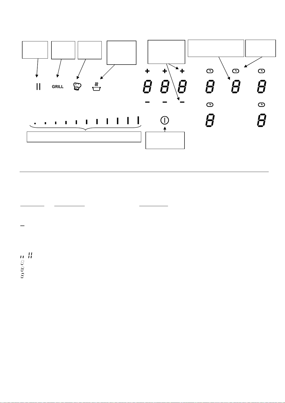
Bandeau de commande
Zone de sélection de puissance «
Slider
»
Minuterie
de zone
Marche/Arrêt
minuterie
au ch
aud
Touche
Stop&Go
Touche
Grill
Touche
Chef
Touche
Maintien
UTILISATION DE L’APPAREIL
Touche [ + ]
et [ - ]
Touche
Touche de sélection
Touche
Affichage
Affichage Désignation Description
0 Zéro La zone de chauffe est activée.
1…9 Niveau de puissance Choix du niveau de cuisson.
U Non détection de casserole Récipient manquant ou inapproprié.
A Accélérateur de chauffe Cuisson automatique.
E Message d’erreur Défaut de circuit électronique.
H Chaleur résiduelle La zone de cuisson est chaude.
P Power Le Power est activé.
Super Power Le Super Power est activé.
Maintien Chaud La cuisson est maintenue à 70°C.
Maintien Chaud La cuisson est maintenue à 90°C.
II Pause/Rappel La table est en pause.
∏ Bridge 2 zones de cuisson sont combinées.
Maintien Chaud La cuisson est maintenue à 42°C.
Ventilation
Le ventilateur de refroidissement a un fonctionnement entièrement automatique. Il se met en
route à petite vitesse dès que les calories dégagées par l’électronique dépassent un certain seuil.
La ventilation enclenche sa seconde vitesse lorsque la table de cuisson est utilisée
intensivement. Le ventilateur réduit sa vitesse et s’arrête automatiquement dès que le circuit
électronique est suffisamment refroidi.
51

MISE EN ROUTE ET GESTION DE L’APPAREIL
“SLIDER“
Accès direct
Avant la première utilisation
Nettoyez votre appareil avec un chiffon humide, puis séchez-le. N’utilisez pas de détergent qui
risquerait de provoquer une coloration bleutée sur les surfaces vitrées.
Principe de l’induction
Une bobine d’induction se trouve sous chaque foyer de cuisson. Lorsque celle-ci est enclenchée,
elle produit un champ électromagnétique variable qui, à son tour produit des courants induits
dans le fond ferro-magnétique du récipient. Il en résulte un échauffement du récipient placé sur la
zone de chauffe.
Bien entendu le récipient doit être adapté:
• Sont recommandés tous les récipients métalliques ferro-magnétiques (à vérifier
éventuellement avec un petit aimant) tels que: cocotte en fonte, poêle en fer noir,
casseroles métalliques émaillées, en inox à semelle ferro-magnétique…
• Sont exclus les récipients en cuivre, inox, aluminium, verre, bois, céramique, grès, terre
cuite, inox non ferro-magnétique…
La zone de cuisson à induction prend automatiquement en compte la taille du récipient utilisé.
Avec un diamètre trop petit, le récipient ne fonctionne pas. Ce diamètre varie en fonction du
diamètre de la zone de cuisson.
Lorsque le récipient n’est pas adapté à la table de cuisson le symbole ( U ) reste affiché.
Touches sensitives
Votre appareil est équipé de touches sensitives permettant de commander les différentes
fonctions. Un effleurage de la touche active leur fonctionnement. Cette activation est validée par
un voyant, un affichage et/ou par un signal sonore.
Dans le cas d’une utilisation générale n’appuyez que sur une seule touche à la fois.
Zone de sélection de puissance « SLIDER » et de réglage de la minuterie
Pour la sélection de la puissance par le slider faire glisser votre doigt sur la zone “SLIDER“.
Vous bénéficiez également d’un accès direct en posant votre doigt directement sur le niveau
souhaité.
Zone de sélection de puissance
“SLIDER“
52

Mise en route
• Enclencher / arrêter la table de cuisson:
Action Bandeau de commande Afficheur
Enclencher appuyer 2 sec. sur [ ] [ 0 ]
Arrêter appuyer 2 sec. sur [ ] aucun ou [ H ]
• Réglage de la zone de chauffe:
Action Bandeau de commande Afficheur
Sélectionner la puissance glisser sur le « SLIDER » [ 1 ] à [ P ]
vers la droite ou la gauche
Arrêter glisser sur le « SLIDER » jusqu’à [ 0 ] [ 0 ] ou [ H ]
Si aucun réglage n’est fait dans un délai de 20 secondes, l’électronique revient en position
d’attente.
Détection de récipient
Pour davantage de confort et de simplicité, cette table de cuisson est équipée d’une commande
interactive. Après allumage de la table, lorsque vous posez une casserole sur la plaque de
cuisson, la commande détecte automatiquement sa position et vous informe du slider à
manipuler en affichant le symbole « 0 » au-dessus de celui-ci. Il ne vous reste plus qu’à
sélectionner le niveau de cuisson désiré.
La détection de récipient assure une sécurité parfaite. L’induction ne fonctionne pas:
• Lorsqu’il n’y a pas de récipient sur la zone de cuisson ou lorsque ce récipient est inadapté
à l’induction. Dans ce cas il est impossible d’augmenter la puissance et dans l’afficheur le
symbole [ U ] apparaît. Le [ U ] disparaît lorsqu’une casserole est posée sur le foyer de
cuisson.
• Si en cours de cuisson le récipient est enlevé de la zone de cuisson, le fonctionnement est
interrompu. Dans l’afficheur le symbole [ U ] apparaît. Le [ U ] disparaît lorsque le récipient
est remis sur le foyer de cuisson. La cuisson reprend au niveau de puissance sélectionnée
au préalable.
Après utilisation, éteignez la zone de chauffe. Ne laissez pas la détection de casserole [ U ]
active.
Indicateur de chaleur résiduelle
Après l’arrêt des zones de cuisson ou l’arrêt complet de la table, les zones de cuissons sont
encore chaudes et sont signalées par le symbole [ H ].
Le symbole [ H ] s’éteint lorsque les zones de cuisson peuvent être touchées sans danger.
Tant que les témoins de chaleur résiduelle sont allumés, ne touchez pas les zones de cuisson et
ne posez aucun objet sensible à la chaleur. Risque de brûlure et d’incendie !
53
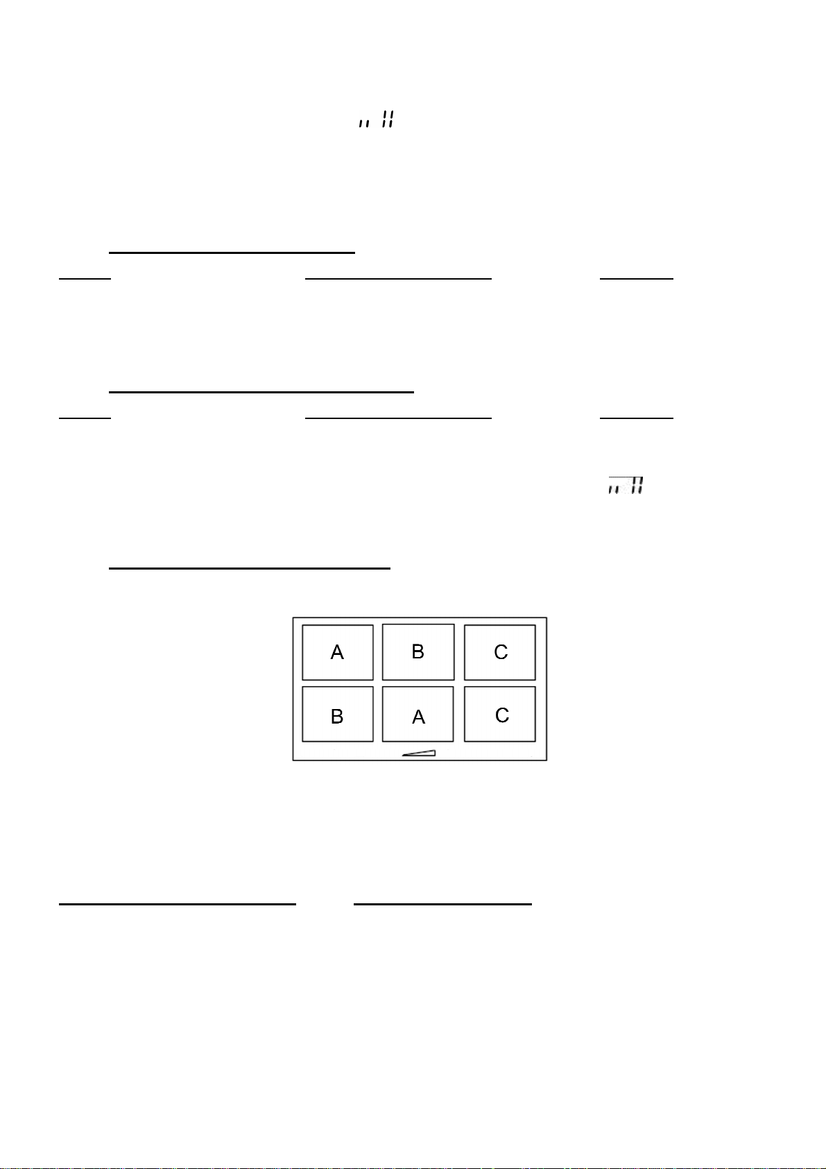
Fonction booster et double booster
La fonction Power [ P ] et Super Power [ ] octroie un renforcement de puissance à la zone
de cuisson sélectionnée.
Si ces fonctions sont activées, les zones de cuisson fonctionnent pendant 10 minutes avec une
puissance nettement plus élevée.
Le Booster et le Double Booster sont conçus par exemple pour faire chauffer rapidement de
grandes quantités d’eau, comme pour la cuisson des pâtes.
• Enclencher / arrêter le booster:
Action Bandeau de commande Afficheur
Enclencher le booster glisser jusqu’à la fin du « SLIDER » [ P ]
ou appuyer directement sur la fin du
« SLIDER »
Stopper le booster glisser sur le « SLIDER » [ 9 ] à [ 0 ]
• Enclencher / arrêter le double booster:
Action Bandeau de commande Afficheur
Enclencher le booster glisser jusqu’à la fin du « SLIDER » [ P ]
ou appuyer directement sur la fin du
« SLIDER »
Enclencher le double booster ré-appuyer sur la fin du « SLIDER » [ clignote avec P ]
Stopper le double booster glisser sur le « SLIDER » [ P ] à [ 0 ]
Stopper le booster glisser sur le « SLIDER » [ 9 ] à [ 0 ]
• Gestion de la puissance maximale :
La table est divisée en trois ensembles de zones de chauffe distincts, chacune ayant une
puissance maximale.
Lorsque la fonction Booster (ou double booster) est activée, et pour ne pas excéder cette
puissance maximale, la commande électronique réduit automatiquement le niveau de cuisson de
l’autre zone de chauffe de l’ensemble.
Durant quelques secondes, l’afficheur de cette zone de cuisson clignote puis affiche le niveau de
cuisson maximum possible :
Zone de cuisson sélectionnée Autre zone de cuisson (exemple: puissance niveau 9)
[ P ] est affiché [ 9 ] passe à [ 8 ] et clignote
Il est possible d’activer la fonction booster (ou double booster) sur plusieurs zones à la fois, pour
cela il faut utiliser des zones d’ensembles différents (A-B, A-C, B-C ou A-B-C).
54

Fonction minuterie
La minuterie peut être affectée simultanément à tous les foyers de cuisson et ceci avec des
réglages de temps de minuterie différents (de 0 à 1H59 minutes) pour chacune des zones.
• Réglage ou modification de la durée de cuisson:
Action Bandeau de commande Afficheur
Sélectionner une zone Appuyer sur une touche de
Sélection de zone [ 0 ]
Sélectionner la puissance glisser sur le « SLIDER » [ 1 ] à [ P ]
Sélectionner la minuterie appuyer sur [ ] voyant minuterie de la
zone de cuisson allumé
Diminuer la durée appuyer sur [ - ] de la minuterie [ 60 ] passe à 59, 58, …
Augmenter la durée appuyer sur [ + ] de la minuterie le temps augmente
Après quelques secondes, le voyant [ ] passe de « clignotement » à « fixe ».
La durée est sélectionnée et le décompte démarre.
• Arrêter la fonction minuterie cuisson:
Action Bandeau de commande Afficheur
Sélectionner la minuterie appuyer sur [ ] le temps s’affiche
Arrêt de la minuterie appuyé sur [ - ] de la minuterie [ 000 ]
Lorsque plusieurs minuteries sont activées il suffit de répéter l’opération.
• Minuterie utilisée hors cuisson:
La minuterie fonctionne indépendamment des foyers et se désactive dès la mise en route d’une
zone de chauffe. Si elle est activée et que la table de cuisson est arrêtée, la minuterie continue
jusqu’à ce que le temps imparti soit écoulé.
Action Bandeau de commande Afficheur
Activer la table de cuisson appuyer 2 sec. sur [ ] [ 0 ]
Sélectionner la minuterie appuyer sur [ 000 ] [ 000 ]
Diminuer la durée appuyer sur [ - ] de la minuterie [ 60 ] passe à 59, 58, …
Augmenter la durée appuyer sur [ + ] de la minuterie le temps augmente
Après quelques secondes, le voyant [ ] passe de « clignotement » à « fixe ».
La durée est sélectionnée et le décompte démarre.
• Arrêt automatique en fin de cuisson:
Dès que le temps de cuisson sélectionné est écoulé la minuterie affiche en clignotant [ 000 ] et
un signal sonore retentit.
Pour stopper le son et le clignotement, il suffit d’appuyer sur une des touches [ - ] ou [ + ] de la
minuterie.
55
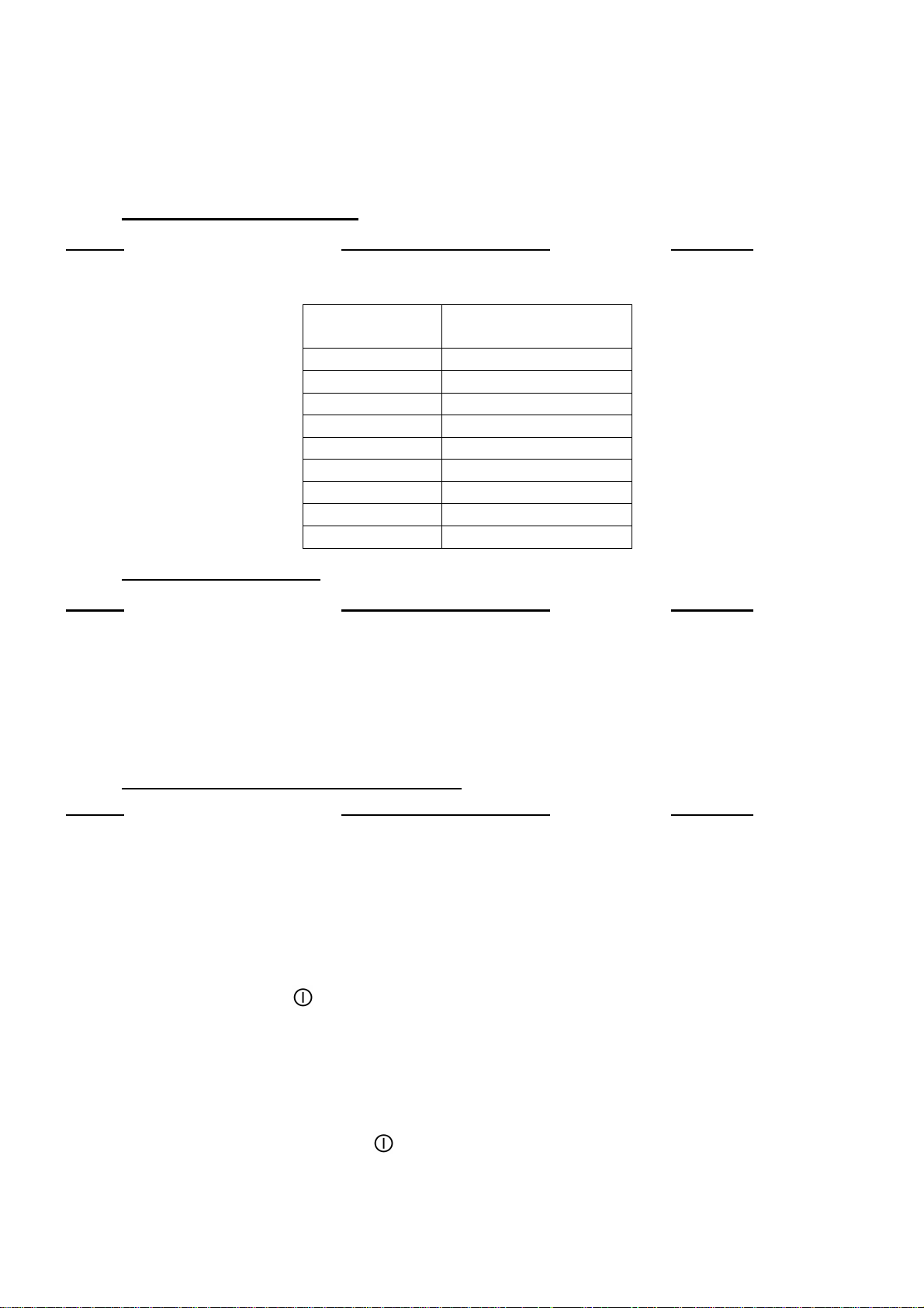
Programmation d’automatisme de cuisson
sélectionnée
de cuisson (Min : S)
1 0:40
2 1:12
3 2:00
4 2:56
5 4:16
6 7:12
7 2:00
8 3:12
9 - : -
Toutes les zones de cuisson sont équipées d’un dispositif de cuisson automatique. La zone de
cuisson se met en marche à pleine puissance pendant un certain temps, puis réduit
automatiquement sa puissance sur le niveau présélectionné.
• Enclencher l’automatisme:
Action Bandeau de commande Afficheur
Activer l’automatisme glisser sur le « SLIDER » jusqu’à [ 7 ] [ 7 ] clignote avec [ A ]
(par exemple « 7 ») et rester appuyé pendant 3s
Puissance
• Arrêter l’automatisme:
Action Bandeau de commande Afficheur
Sélectionner la puissance glisser sur le « SLIDER » [ 0 ] à [ 9 ]
Temps automatisme
Fonction Stop&Go
Cette fonction permet d’interrompre temporairement la cuisson et de la réactiver avec les mêmes
réglages.
• Enclencher / arrêter la fonction pause:
Action Bandeau de commande Afficheur
Activer la pause appuyer sur [ II ] 2s [ II ] sur les afficheurs
voyant pause allumé
Stopper la pause appuyer sur [ II ] 2s animation des voyants
les réglages précédent
s’affichent
Fonction rappel
Après avoir éteint la table ( ), il est possible de rappeler les derniers réglages sélectionnés:
• Etat de cuisson de toutes les zones de cuisson (puissance).
• Minutes et secondes des zones de cuisson programmées par les minuteries.
• Fonction “cuisson automatique”.
• Fonction “maintien chaud”.
La procédure de rappel est la suivante:
• Appuyer 2 sec. sur la touche [
• Appuyer sur [ II ] avant la fin du clignotement du voyant.
Les réglages précédents sont à nouveau actifs.
].
56
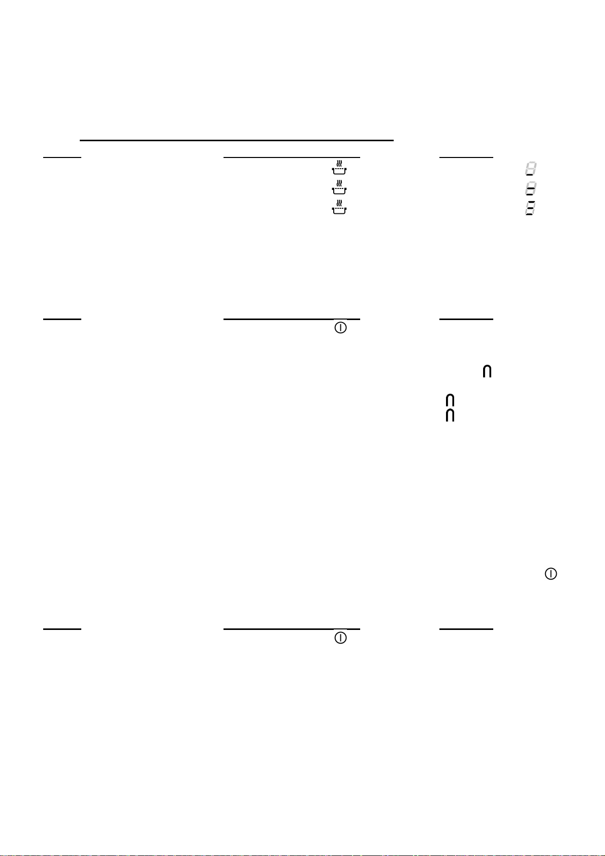
Fonction « Maintien au chaud »
Cette fonction de maintien au chaud permet d’atteindre et de maintenir automatiquement une
température de 42, 70 ou 94°C. La durée maximale de maintien au chaud est de 2 heures.
Ceci évitera aux liquides de déborder et aux mets d’attacher au fond de la casserole.
• Enclencher / arrêter la fonction « Maintien au chaud »:
Action Bandeau de commande Afficheur
Activer le maintien à 42°C appuyer 1 fois sur [ ] [ U ] et voyant [ ]
Activer le maintien à 70°C appuyer 2 fois sur [ ] [ U ] et voyant [ ]
Activer le maintien à 94°C appuyer 3 fois sur [ ] [ U ] et voyant [ ]
Arrêter le maintien au chaud glisser sur le « SLIDER » [ 0 ] à [ 9 ]
Fonction Bridge et Bridge automatique
Cette fonction permet de combiner 2 zones avec les mêmes fonctionnalités qu’une seule zone.
Action Bandeau de commande Afficheur
Mise en route appuyer 2 sec. sur [ ] [ 0 ]
Activer le bridge Manuellement : appuyer simultanément
sur les 2 touches de sélection
des 2 zones à combiner [ 0 ] et [ ]
ou
Automatique : poser une grande [ ] clignote
casserole sur les 2 zones à bridger [ ]
Sélectionner la puissance glisser sur le « SLIDER »
correspondant à l’affichage de la [ 1 ] à [ 9 ]
puissance
Arrêter le bridge appuyer simultanément sur
les 2 touches de selection [ 0 ]
des 2 zones combinées
Verrouillage du bandeau de commande
Pour éviter de modifier une sélection de la table de cuisson, notamment dans le cadre du
nettoyage de la vitre, le bandeau de commande (à l’exception de la touche marche/arrêt [ ])
peut être verrouillé. Cette fonctionnalité ne peut être activé que dans 10 secondes après le
démarrage de l’appareil.
Action Bandeau de commande Afficheur
Activer la table appuyer 2 sec. sur [ ] [ 0 ]
Verrouiller la table maintenir pendant 3s la touche d’une [ L ]
zone puis appuyer sur le « Slider » qui
défile et glisser le doigt de la gauche
vers la droite
Déverrouiller la table maintenir pendant 3s la touche d’une [ 0 ] ou [ H ]
zone puis appuyer sur le « Slider » qui
défile et glisser le doigt de la droite
vers la gauche
57

Fonction chef
Cette fonction change la plaque de cuisson en 2 grandes zones.
• Enclencher / arrêter la fonction chef:
Action Bandeau de commande Afficheur
Activer la fonction chef appuyer sur [ ] [ 3 ] et [ ], [ 9 ] et [ ]
Stopper la fonction chef appuyer sur [ ] [ 0 ]
Fonction Grill
Cette fonction permet d’utiliser de façon optimal le grill en combinant 2 zones et en utilisant des
puissances appropriées.
• Enclencher / arrêter la fonction grill:
Action Bandeau de commande Afficheur
Activer la fonction Grill appuyer sur [ GRILL ] [ ]
Stopper la fonction Grill appuyer sur [ GRILL ] [ 0 ]
Fonction Pot Speed Test
La casserole est une composante importante d’un système à induction. Vous devez donc vous
assurer que la casserole que vous utilisez vous offre la meilleure expérience en vous permettant
d’exploiter au maximum les capacités de votre table à induction.
La fonction Pot Speed Test vous permet de mesurer l’efficacité et la vitesse de cuisson de votre
casserole.
Ce test peut uniquement être effectué quand il n’y pas d’opérations de cuisson en cours, et
uniquement sur la zone spécifiée ci-dessous.
Chaque action doit être réalisée dans les 6s après la précédente..
Mettre la casserole sur la zone de test
Foyer de
test
58

Allumer la table
Appuyer su
r le “SLIDER”
test
Appuyer sur la touche on/off [ ]
Dans les 6s après le démarrage
Activer la fonction
Appuyer simultanément sur la touche maintien chaud [ ] et sur le “SLIDER”.
[ 0 ], [ t ] sont affichés.
Le [ 0 ] est fixe.
Appuyer sur la touche
maintien chaud
Les [ t ] clignotent.
Démarrer le test
Appuyer sur le “SLIDER”.
Le [ 0 ] est en mouvement.
Les [ t ] clignotent.
Résultats du test
Résultats du
59

Par exemple, un résultat de vitesse de casserole de niveau 7:
Symboles
Indication
La casserole est classée dans l’une de ces 3 catégories, et son niveau de vitesse précis est
défini à l’aide du bar graph.
Niveau de vitesse faible, cette casserole n’est pas conseillée pour
une table à induction.
Catégorie
de vitesse
Niveau de
Niveau de vitesse moyen, cette casserole est adaptée à une table à
Conseils importants :
Certaines casseroles peuvent avoir une si mauvaise compatibilité qu’elles ne sont même pas
reconnues par la table. Dans ce cas-là, l’afficheur affichera le symbole [ ] .
La casserole doit être toujours être centrée sur la zone de test, dans le cas contraire le résultat
pourrait être faussé.
Le résultat est affiché pendant 3s, après cela la table switch automatiquement en mode normal,
et vous pouvez l’utiliser pour cuisiner.
Notez que le niveau de vitesse n’est pas le seul critère important pour juger de la qualité de votre
casserole et vous assurer qu’elle est parfaitement compatible avec votre table de cuisson. Pour
plus de détails, veuillez-vous référer au chapitre « Conseils de cuisson ».
induction.
Niveau de vitesse élevé, cette casserole offre la meilleure expérience
de cuisine à induction.
60

CONSEILS DE CUISSON
Qualité des casseroles
Matériaux adaptés: acier, acier émaillé, fonte, inox à fond ferro-magnétique,
aluminium à fond ferro-magnétique.
Matériaux non adaptés: aluminium et inox à fond non ferro-magnétique, cuivre, laiton, verre,
céramique, porcelaine.
Les fabricants spécifient si leurs produits sont compatibles induction.
Pour vérifier si des casseroles sont compatibles:
• Placez un peu d’eau dans une casserole placée sur une zone de cuisson induction réglée
au niveau [ 9 ]. Cette eau doit chauffer en quelques secondes.
• Placez un aimant sur le fond externe de la casserole, il doit rester collé.
Certaines casseroles peuvent faire du bruit lorsqu’elles sont placées sur une zone de cuisson à
induction. Ces bruits ne traduisent en aucun cas un défaut de l’appareil et n’influent nullement
sur son fonctionnement.
La qualité du fond de la casserole peut influencer l’uniformité de la cuisson et le enregistrement
de puissance de la casserole.
N’utilisez que des casseroles et des poêmes à fond lisse. Les bases rugueuses des casseroles
et des poêles raient le verre.
Utilisez de préférence des sauteuses à bords droits. Pour les poêles aux bords inclinés,
l’induction agit aussi dans les zones de bordure de la poêle. Par conséquent, le bord des poêles
se décolore.
Dimension des casseroles
Les zones de cuisson s’adaptent automatiquement à la dimension du fond de la casserole
jusqu’à une certaine limite. Le fond de cette casserole doit cependant avoir un diamètre minimum
en fonction du diamètre de la zone de cuisson correspondante.
Afin d’obtenir le rendement maximum de votre table de cuisson, veuillez placer la casserole bien
au centre de la zone de cuisson.
61

Exemples de réglage des puissances de cuisson
Réchauffer
Plats
pré-cuisinés
Décongélation
Légumes, poisson, produits congelés
Légumes frais
Goulasch, roulades, tripes
Frire
Porter à ébullition
eau
d’eau
(Les valeurs ci-dessous sont indicatives)
1 à 2
Faire fondre
Sauces, beurre, chocolat, gélatine
2 à 3
3 à 4 Vapeur Légumes, poissons, viande
4 à 5 Eau
6 à 7 Cuire à feu doux
7 à 8
9
P et
Gonfler
Cuire
Frire,
Frire, Porter à ébullition
Riz, pudding et plats cuisinés
Pommes de terre à l’eau, soupes, pâtes
Viandes, foie, œufs, saucisses
Pommes de terre, beignets, galettes
Steaks, omelettes
Porter à ébullition des quantités importantes
ENTRETIEN ET NETTOYAGE
Pour nettoyer, il faut mettre l’appareil hors fonctionnement.
Laissez refroidir l’appareil, car risques de brûlures.
• Nettoyez les restes de cuisson avec de l’eau additionnée de produit vaisselle ou un
produit du commerce conseillé pour la vitrocéramique.
• N’utilisez en aucun cas d’appareils « à vapeur » ou « à pression ».
• Ne pas utiliser d’objets qui risqueraient de rayer la vitrocéramique (tel que tampon abrasifs
ou pointe de couteau…).
• N’utilisez pas de produits de nettoyage abrasifs qui pourraient endommager l’appareil.
• Séchez l’appareil avec un chiffon propre.
• Enlevez immédiatement le sucre et les mets contenant du sucre.
QUE FAIRE EN CAS DE PROBLÈME
La table de cuisson ou les zones de cuisson ne s’enclenchent pas:
• La table est mal connectée au réseau électrique.
• Le fusible de protection a sauté.
• Vérifiez si le verrouillage n’est pas activé.
• Les touches sensitives sont couvertes d’eau ou de graisse.
• Un objet est posé sur les touches sensitives.
Le symbole [ U ] s’affiche:
• Il n’y a pas de casserole sur la zone de cuisson.
• Le récipient utilisé n’est pas compatible avec l’induction.
• Le diamètre du fond de casserole est trop petit par rapport à la zone de cuisson.
Le symbole [ E ] s’affiche:
• Le système électronique est défectueux.
• Débranchez et rebranchez l’appareil.
• Appelez le Service Après-ventes.
62

L’une des zones ou l’ensemble du plan de cuisson se déclenche:
• Le déclenchement de sécurité a fonctionné.
• Celui-ci s’actionne dans le cas ou vous avez oublié de couper une des zones de chauffe.
• Il s’enclenche également lorsqu’une ou plusieurs touches sensitives sont couvertes.
• Une des casseroles est vide et son fond a surchauffé.
• La table dispose également d’un dispositif de réduction automatique de niveau de
puissance et de coupure automatique en cas de surchauffe.
La soufflerie de ventilation continue de tourner après l’arrêt de la table:
• Ce n’est pas un défaut, le ventilateur continue de protéger l’électronique de l’appareil.
• La soufflerie s’arrête automatiquement.
La commande de cuisson automatique ne s’enclenche pas:
• La zone de cuisson est encore chaude [ H ].
• Le niveau de cuisson maximum est enclenché [ 9 ].
Le symbole [ U ] s’affiche:
• Se référer au chapitre “Maintien chaud“.
Le symbole [ II ] s’affiche:
• Se référer au chapitre “Pause“.
Le symbole [ ] ou [ Er03 ] s’affiche :
• Un objet ou un liquide recouvre les touches de la commande. Le symbole disparaît une
fois les touches libérées ou nettoyées.
Le symbole [ E2 ] s’affiche :
• La table est en surchauffe, laissez-la refroidir puis rallumez-la.
Le symbole [ E8 ] s’affiche :
• L’entrée d’air du ventilateur est obstruée, libérez-la.
Le symbole [ U400 ] s’affiche :
• La table est mal connectée au réseau. Vérifiez le branchement et rebranchez la table.
Le symbole [ Er47 ] s’affiche :
• La table est mal connectée au réseau. Vérifiez le branchement et rebranchez la table.
Si un des symboles ci-dessus persiste, appelez le SAV.
PROTECTION DE L’ENVIRONNEMENT
• Les matériaux d’emballage sont écologiques et recyclables.
• Les appareils électroniques sont composés de matériaux recyclables et parfois de
matériaux nocifs pour l’environnement, mais nécessaires au bon fonctionnement et à la
sécurité de l’appareil.
• Ne jetez en aucun cas votre appareil avec les déchets
ménagers.
• Faites appel au service d’enlèvement ou aux sites de
dépôt mis en place par votre commune et adaptés au
recyclage des appareils électroménagers.
63

INSTRUCTIONS D’INSTALLATION
découpe
dite «
à fleur
»
Type
Larg.
Prof.
Larg.
Prof.
Rayon
Larg.
Prof.
Ep.
P906IM3G5NE
750
490
886
526
8
880
520
4
Le montage relève de la compétence exclusive de spécialistes.
L’utilisateur est tenu de respecter la législation et les normes en vigueur dans son pays de
résidence.
Mise en place du joint d’étanchéité
Le joint adhésif fourni avec l’appareil permet d’éviter toute infiltration dans le meuble.
Sa mise en place doit être effectuée avec un grand soin suivant le croquis ci-dessous.
Coller le joint (2) sur le rebord de la
table à 2mm du bord externe, après
avoir ôté la feuille de protection (3).
Encastrement
• La découpe du plan de travail sera suivant le modèle de table de:
Dimension de
Dimension de découpe
Dimension du verre
• La distance entre la table de cuisson et le mur doit être au minimum de 50mm.
• La table de cuisson est un appareil qui appartient à la classe de protection « Y ». Lors de
son encastrement, une paroi d’armoire haute ou un mur peut se trouver sur l’un des côtés
et sur la face arrière. Mais de l’autre côté, aucun meuble ni aucun appareil ne doit
être plus haut que le plan de cuisson.
• Les placages et revêtements des plans de travail doivent être réalisés en matériaux
résistant à la chaleur (100°C).
• Les baguettes de bord murales doivent être thermo résistantes.
• Les matériaux des plans de travail peuvent gonfler au contact de l’humidité. Pour protéger
le chant de la découpe, appliquer un vernis ou une colle spéciale.
• N’installer pas la table au dessus d’un four non ventilé ou d’un lave-vaisselle.
• Garantir entre le fond du caisson de l’appareil un espace de 20 mm pour assurer une
bonne circulation de l’air de refroidissement de l’électronique.
• Si un tiroir se trouve sous le plan de cuisson, éviter d’y ranger des objets inflammables
(par exemple: spray) et des objets non résistants à la chaleur.
• L’écart de sécurité entre la table de cuisson et la hotte aspirante placée au-dessus d’elle
doit respecter les indications du fabricant de hottes. En cas d’absence d’instructions
respecter une distance minimum de 760 mm.
• Le câble de raccordement ne doit être soumis, après encastrement, à aucune contrainte
mécanique, comme par exemple du fait d’un tiroir.
• MISE EN GARDE: Utiliser uniquement les dispositifs de protection de table de cuisson
conçus par le fabricant de l’appareil de cuisson ou indiqués par le fabricant de l’appareil
dans les instructions d’utilisation comme adaptés ou les dispositifs de protection de table
de cuisson intégrés à l’appareil. L’utilisation de dispositifs de protection non appropriés
peut entrainer des accidents.
64
CONNEXION ÉLECTRIQUE
• L’installation de cet appareil et son branchement au réseau électrique ne doit être confiés
qu’à un électricien parfaitement au fait des prescriptions normatives.
• La protection contre les pièces sous tension doit être assurée après le montage.
• Les données de raccordement nécessaires se trouvent sur la plaque signalétique et la
plaque de branchement placées sous l’appareil.
• Cet appareil doit être séparé du secteur par un dispositif de sectionnement omnipôles.
Lorsque celui-ci est ouvert (déclenché), un écartement de 3mm doit être assuré.
• Le circuit électrique doit être séparé du réseau par des dispositifs appropriés, par exemple
les disjoncteurs, les fusibles, les disjoncteurs différentiels et les contacteurs.
• Si l’appareil n’est pas muni d’une fiche accessible, des moyens de déconnection doivent
être incorporé à l’installation fixe conformément aux réglementations de l’installation.
• Le câble d’alimentation doit être placé de sorte à ce qu’il ne touche pas de parties
chaudes de la table de cuisson.
Attention !
Cet appareil n’est conçu que pour une alimentation en 230 V~ 50 / 60 Hz.
Raccordez toujours le fil de terre de protection.
Respectez le schéma de raccordement.
Le boîtier de raccordement se situe sous la plaque de cuisson. Pour ouvrir le capot, servez-vous
d’un tournevis moyen. Placez le dans les 2 fentes situées à l’avant des 2 flèches.
Branchement de la table:
Réseau Raccordement
230 V~ 50/60 Hz 1 phase +N 3 x 4 mm2
400 V~ 50/60Hz 2 phases + N 4 x 2,5 mm2
400 V~ 50/60Hz 3 phases + N 5 x 1,5 mm2
* calculé avec le coefficient de simultanéité suivant standard EN 60 335-2-6
Section
cordon
d’alimentation
H 05 VV - F
H 05 RR - F
H 05 VV - F
H 05 RR - F
H 05 VV - F
H 05 RR - F
Cordon
Calibre de
disjoncteur
40 A *
25 A *
16 A *
65

Pour vous adapter au réseau électrique, veuillez utiliser les pontets en laiton situés dans le
branchement, ou qui pourrait survenir à l’usage d’un appareil non relié à la terre ou équipé
d’une terre défectueuse.
boitier de connexion
Monophasé 230V~1P+N :
Mettre un pontet entre les plots 1,2 et 3, puis un pontet entre 4 et 5.
Visser le fil vert/jaune au plot prévu pour la mise à la terre, visser le neutre N sur le plot 4 ou 5,
visser la phase L1 sur le plot 1, 2 ou 3.
Biphasé 400V~2P+N :
Mettre un pontet entre les plots 1 et 2, puis un pontet entre 4 et 5.
Visser le fil vert/jaune au plot prévu pour la mise à la terre, visser le neutre N sur le plot 4 ou 5,
visser la phase L1 sur le plot 1 ou 2 et la phase L2 sur le plot 3
Triphasé 400V~3P+N :
Mettre un pontet entre les plots 4 et 5.
Visser le fil vert/jaune au plot prévu pour la mise à la terre, visser le neutre N sur le plot 4 ou 5,
visser la phase L1 sur le plot 1, la phase L2 sur le plot 2 et la phase L3 sur le plot 3.
Attention ! Veillez à bien engager les fils et à bien serrer les vis.
Notre responsabilité ne saurait être engagée pour tout incident résultant d’un mauvais
66

RESUMEN
SEGURIDAD ............................................................................................................................... 68
P
RECAUCIONES ANTES DE UTILIZARLA PARA COCINAR
U
TILIZACIÓN DEL APARATO
P
RECAUCIONES PARA NO DETERIORAR EL APARATO
P
RECAUCIONES EN CASO DE FALLO DEL APARATO
O
TRAS PRECAUCIONES
.......................................................................................................... 69
............................................................................................................... 71
DESCRIPCIÓN DEL APARATO ................................................................................................. 72
C
ARACTERÍSTICAS TECNICAS
Z
ONA DE MANDOS
...................................................................................................................... 72
...................................................................................................... 72
UTILIZACIÓN DEL APARATO ................................................................................................... 73
I
NDICACIONES
V
ENTILACIÓN
............................................................................................................................ 73
............................................................................................................................. 73
PUESTA EN MARCHA Y USO DEL APARATO ......................................................................... 73
A
NTES DE LA PRIMERA UTILIZACIÓN
P
RINCIPIO DE LA INDUCCIÓN
T
ECLAS TÁCTILES
Z
ONA DE SELECCIÓN DE POTENCIA
P
UESTA EN MARCHA
D
ETECCIÓN DEL RECIPIENTE
I
NDICADOR DE CALOR RESIDUAL
F
UNCIÓN BOOSTER
F
UNCIÓN TEMPORIZADOR
C
OCCIÓN AUTOMÁTICA
F
UNCIÓN STOP&GO
F
UNCION RE-LLAMADA
F
UNCIÓN “MANTENER CALIENTE
F
UNCIÓN PUENTE O PUENTE AUTOMÁTICO
B
LOQUEO DEL PANEL DE CONTROL
F
UNCIÓN “CHEF
F
UNCIÓN GRILL
F
UNCIÓN DE PRUEBA DE VELOCIDAD DEL RECIPIENTE DE COCCIÓN
....................................................................................................................... 74
................................................................................................................... 75
..................................................................................................................... 75
................................................................................................................... 78
“ ........................................................................................................................ 79
.......................................................................................................................... 79
........................................................................................................ 74
....................................................................................................... 75
........................................................................................................... 76
............................................................................................................... 77
................................................................................................................ 78
.............................................................................................. 73
“SLIDER”
Y AJUSTE DE MINUTERO
.................................................................................................. 75
” ................................................................................................. 78
.................................................................................... 79
............................................................................................... 79
................................................................... 68
...................................................................... 70
......................................................................... 71
............................................ 74
................................................. 80
CONSEJOS DE COCCIÒN ......................................................................................................... 83
C
ALIDAD DE LAS CACEROLAS
D
IMENSIÓN DE LAS CACEROLAS
E
JEMPLOS DE AJUSTE DE LAS POTENCIAS DE COCCIÓN
....................................................................................................... 83
................................................................................................... 83
.................................................................. 84
CONSERVACIÓN Y LIMPIEZA ................................................................................................... 84
QUÉ HACER EN CASO DE PROBLEMA ................................................................................... 84
PROTECCIÓN DEL MEDIO AMBIENTE..................................................................................... 85
INSTRUCCIONES DE INSTALACIÓN ........................................................................................ 86
CONEXIÓN ELÉCTRICA ............................................................................................................ 87
67

SEGURIDAD
Precauciones antes de utilizarla para cocinar
• Retire todos los elementos del embalaje.
• La instalación y el conexionado eléctrico del aparato deben
encargarse a un especialista autorizado. El fabricante no será
responsable de los daños resultantes de un error de
empotramiento o de conexionado.
• El aparato sólo debe utilizarse si está montado e instalado en
un mueble y una superficie de trabajo homologados y
adaptados.
• Su utilización va únicamente destinada a los usos domésticos
habituales (preparación de alimentos), con exclusión de
cualquier otra utilización doméstica, comercial o industrial.
• Retire todas las etiquetas y autoadhesivos del cristal
vitrocerámico.
• No transforme ni modifique el aparato.
• La placa de cocción no debe servir como soporte ni como
superficie de trabajo.
• La seguridad sólo está asegurada si el aparato está conectado
a una toma de tierra de protección conforme a los reglamentos
vigentes.
• No utilice alargadoras para la conexión a la red eléctrica.
• El aparato no debe utilizarse encima de un lavavajillas o de una
secadora de ropa: los vapores de agua desprendidos podrían
deteriorar la electrónica.
• Este aparato no está previsto para el funcionamiento con un
reloj temporizador externo o un mando a distancia.
68

Utilización del aparato
• Apague siempre los fogones después de utilizarlos.
• Vigile constantemente los guisos que utilizan grasas y aceites,
ya que son susceptibles de inflamarse rápidamente.
• Tenga cuidado del riesgo de quemaduras durante y después
de la utilización del aparato.
• Los niños no deben manipular el aparato.
• Asegúrese de que ningún cable eléctrico, fijo o móvil, del
aparato toca el cristal o el recipiente caliente.
• Los objetos magnetizables (tarjetas de crédito, disquetes
informáticos, calculadoras) no deben estar cerca del aparato en
funcionamiento.
• No coloque ningún objeto metálico, excepto los recipientes a
calentar. En caso de conexión accidental o de calor residual,
este objeto, según el material, tiene el riesgo de fundirse o de
empezar a arder.
• No cubra nunca el aparato con un trapo o con una hoja de
protección. Podría calentarse mucho y encenderse.
• Este aparato electrodoméstico puede ser usado por niños a
partir de 8 años e igualmente por personas con capacidades
físicas, sensoriales o mentales reducidas o que carezcan falta
de experiencia y conocimiento del producto si se les ha dado
la supervisión instrucción adecuada para el uso del mismo de
un modo seguro y entienden de igual manera los peligros que
puedan implicar.
• Los niños no deben usar éste electrodoméstico para jugar.
• La limpieza o el uso de éste aparato no debe realizarse por
niños sin supervisión.
69

Precauciones para no deteriorar el aparato
• Las cacerolas con base sin pulir (fundición no esmaltada,…) o
estropeadas pueden dañar la vitrocerámica.
• La presencia de arena u otros materiales abrasivos puede
dañar la vitrocerámica.
• Evite dejar caer objetos, aunque sean pequeños, sobre la
vitrocerámica.
• No dé golpes a los bordes del cristal con las cacerolas.
• Asegúrese de que la ventilación del aparato se haga según las
instrucciones del fabricante.
• No coloque ni deje cacerolas vacías sobre la placa de cocción.
• Evite que azúcar, materiales sintéticos o papel de aluminio
toquen las zonas calientes. Estas substancias pueden, al
enfriarse, provocar roturas u otras modificaciones en la
superficie vitrocerámica: desconecte al aparato y retírelas
inmediatamente de la zona de cocción cuando aún está
caliente (atención: peligro de quemaduras).
• No almacenar objetos sobre la placa de cocción
• No coloque nunca recipientes calientes sobre la zona de los
mandos.
• Si hay un cajón situado bajo el aparato empotrado, asegúrese
que hay distancia suficiente (2 cm) entre el contenido de este
cajón y la parte inferior del aparato con el fin de asegurar una
buena ventilación.
• No deposite objetos inflamables (por ejemplo sprays) en el
cajón situado bajo la placa de cocción. Las eventuales
bandejas para cubiertos deben ser de material resistente al
calor.
70

Precauciones en caso de fallo del aparato
ENTORNO.
• Si se constata una avería, es necesario desconectar el aparato
y desenchufar la línea de alimentación eléctrica.
• En caso de desconchados o fisuras en la vitrocerámica es
imperativo desconectar el aparato de la red eléctrica y avisar al
servicio posventa.
• Las reparaciones sólo pueden ser realizadas por personal
especializado. En ningún caso abra el aparato usted mismo.
• ADVERTENCIA: Si la superficie está agrietada, apagar el
aparato para evitar la posibilidad de descargas eléctricas.
Otras precauciones
• Asegúrese siempre de que el recipiente de cocción esté
centrado en la zona de cocción. El fondo de la cacerola debe
cubrir, tanto como sea posible, la zona de cocción.
• Para usuarios que lleven un marcapasos, el campo magnético
puede influir en su funcionamiento. Le recomendamos se
asesore con el proveedor o el médico.
• No utilice recipientes de material sintético o de aluminio:
podrían fundirse sobre los fogones aún calientes.
• El deshecho de este aparato requiere un procedimiento
especial. Consulte con su administración local sobre las
posibilidades de reciclaje.
• No apagar nunca con agua un fuego. Apagar la zona de
cocción. Sofocar con cuidado las llamas con una tapa, una tapa
extintora u otro medio similar.
EL USO DE OLLAS INADECUADAS O DE UN CRISTAL
ADAPTADOR PARA INDUCCIÓN ORIGINA LA
CONCLUSIÓN PREMATURA DE LA GARANTÍA.
EL FABRICANTE NO ASUME NINGUNA
RESPONSABILIDAD POR DAÑOS QUE PUEDAN
PRODUCIRSE EN LA PLACA DE COCINA O EN SU
71

DESCRIPCIÓN DEL APARATO
Modelo
P906IM3G5NE
Potencia total
11100 W
Consumo energético p
ara placas EC
** 188 Wh/kg
Zona
frontal izquierda
21
0 x 190 mm
Diámetro mínimo
Ø 100 mm
Potencia nominal *
2100 W
Potencia de refuerzo *
2600 W
Doble
Potencia de refuerzo
* 3700 W
Utensilios de cocina
**
Ø 150 mm
(x2)
Consumo energetico E
Ccw** 182.8 Wh/kg
Utensilios de cocina
**
Ø 180 mm (x2)
Consumo energetico EC
** 190.6 Wh/kg
Utensilios de cocina
**
Ø 210 mm (x2)
Consumo energetico EC
** 188.1 Wh/kg
“Slider”
On / Off
Seleccionar zona
Timer
Timer [ + ] y
[- ]
Mantener
Características técnicas
hob
cw
cw
* la potencia puede variar en función de las dimensiones y de los materiales de las cacerolas.
** calculado según método de medida (EN 60350-2)
Zona de mandos
Pausa/
Re-
llamada
Función
Grill
Zona de selección de potencia
Función
Chef
caliente
72

UTILIZACIÓN DEL APARATO
Indicaciones
Indicación Designación Función
0 Cero Zona de cocción activada
1…9 Nivel de potencia Elección nivel de cocción
U Detección de cacerola Falta recipiente o es inadecuado
A Acelerador de calor Cocción automática
E Mensaje de error Fallo electrónico
H Calor residual La zona de cocción aún caliente
P Booster Activada la potencia Booster
Doble Booster Activada la potencia Doble Booster
Mantener caliente La placa mantiene el recipiente a
temperatura constante de42°
Mantener caliente La placa mantiene el recipiente a
temperatura constante de70°
Mantener caliente La placa mantiene el recipiente a
temperatura constante de94°
II Stop&Go La pausa está activada
∏ Bridge 2 zonas de cocción se combinan
Ventilación
El ventilador de enfriamiento tiene un funcionamiento totalmente automático. Se pone en marcha
a velocidad baja a partir del momento en que el calor desprendido por el sistema electrónico
sobrepasa un cierto umbral. La ventilación activa su velocidad más alta cuando la placa de
cocción se usa de forma intensiva. El ventilador reduce su velocidad y se para automáticamente
cuando el circuito electrónico está suficientemente frío.
PUESTA EN MARCHA Y USO DEL APARATO
Antes de la primera utilización
Limpie el aparato con un trapo húmedo y séquelo. No utilice detergente ya que podría provocar
una coloración azulada en las superficies vitrificadas.
73

Principio de la inducción
“SLIDER“
Acceso directo
Debajo de cada placa de cocción hay una bobina de inducción. Cuando ésta está conectada,
produce un campo electromagnético variable el cual produce a su vez corrientes inducidas en el
fondo ferromagnético del recipiente. De ello resulta un calentamiento del recipiente colocado
sobre la zona de calentamiento.
Como es lógico, el recipiente debe ser adecuado:
• Se recomiendan todos los recipientes metálicos ferro-magnéticos (a verificar
eventualmente con un pequeño imán) tales como: cazuelas de fundición, sartenes de
hierro negro, cacerolas metálicas esmaltadas, en acero inoxidable con base ferromagnética…
• Quedan excluidos los recipientes de cobre, inoxidable, aluminio, cristal, madera,
cerámica, gres, barro cocido, inoxidable no ferro-magnético…
La zona de cocción por inducción tiene automáticamente en cuenta el tamaño del recipiente
utilizado. Con un diámetro demasiado pequeño, el recipiente no funciona. Este diámetro varía en
función del diámetro de la zona de cocción.
Cuando el recipiente no es adecuado para la placa de cocción, queda encendido el símbolo (U).
Teclas táctiles
Su aparato está provisto de teclas táctiles que permiten controlar las distintas funciones. Un
pequeño roce con la tecla activa su funcionamiento. Esta activación queda confirmada por un
piloto, un indicador y/o por una señal sonora.
No toque una tecla más de una vez.
Zona de selección de potencia “SLIDER” y ajuste de minutero
Para la selección de potencia con el slider deslizar el dedo sobre la zona “SLIDER”.
Se beneficia de un acceso directo apoyando el dedo directamente en el nivel deseado.
Zona de selección de potencia
“SLIDER“ y ajuste de minutero
74

Puesta en marcha
• Conectar / Apagar la placa de cocción:
Acción Zona de mandos Indicador
Conectar pulsar [ ] 2 s. [ 0 ] parpadear
Apagar pulsar [ ] 2 s. ninguno o [ H ]
• Conectar / Apagar una zona de calentamiento:
Acción Zona de mandos Indicador
Aumentar la potencia Deslizarse por la GUÍA DESLIZANTE [ 1 ] a [ P ]
Desconectar Deslizarse por la GUÍA DESLIZANTE
hasta 0 [ 0 ] o [ H ]
Si no se realiza ningún ajuste en el plazo de 20 segundos, el sistema vuelve a la posición de
espera.
Detección del recipiente
La detección del recipiente asegura una seguridad perfecta. La inducción no funciona:
• Cuando no hay recipiente sobre la zona de cocción o cuando este recipiente no es
adecuado para la inducción. En este caso es imposible aumentar la potencia y aparece el
símbolo [ U ] en el indicador. La [ U ] desaparece cuando se coloca una cacerola en la
zona de cocción.
• Si en el curso de la cocción se retira el recipiente de la zona de cocción, el funcionamiento
se interrumpe. Aparece el símbolo [ U ] en el indicador. La [ U ] desaparece cuando se
coloca de nuevo el recipiente en la zona de cocción. La cocción se reemprende en el nivel
de potencia seleccionado anteriormente.
Después la utilización de la placa, es necesario apagar la zona de cocción. No dejan activa la
detección de la cacerola.
Indicador de calor residual
Después de apagar las zonas de cocción o de apagar por completo la placa, las zonas de
cocción están aún calientes lo que se indica con el símbolo [ H ]
El símbolo [ H ] se apaga cuando las zonas de cocción se pueden tocar sin peligro.
Mientras los testigos de calor residual estén encendidos, no toque las zonas de cocción ni ponga
encima ningún objeto sensible al calor ¡Peligro de quemadura y de incendio!
Función booster
Todas las zonas están provistas de una función power y una función de potencia doble, esto es,
de una amplificación de potencia. La función power se visualiza con [ P ]. La función super power
se visualiza parpadeando [ ] con [ P ].
Si están conectadas, dichas zonas de cocción trabajan durante 10 minutos. Esa alta potencia
está concebida p. ej. para que pueda calentar rápidamente grandes cantidades de agua, como
para cocer agua de fideos.
• Conectar/ desconectar booster:
Accionamiento Panel de control Indicación
Conectar booster Deslizarse por la guía deslizante hasta el final
o presionar al final [ P ]
Desconectar booster Deslizarse por la GUÍA DESLIZANTE [ 9 ] a [ 0 ]
75

• Conectar/ desconectar doble booster:
Accionamiento Panel de control Indicación
Conectar booster Deslizarse por la GUÍA DESLIZANTE [ P ]
hasta el final
o presionar al final
Conectar doble booster Presionar al final [ parpadea
con [ P ]
Desconectar doble booster Deslizarse por la GUÍA DESLIZANTE [ P ] a [ 0 ]
Desconectar booster Deslizarse por la GUÍA DESLIZANTE [ 9 ] a [ 0 ]
• Gestión de la energía:
La placa se divide en 3 grupos separados de zonas de calentamiento, cada juego tiene una
potencia máxima.
Si los niveles de potencia seleccionados para ambas zonas superan la cantidad máxima
disponible de la energía, la función de administración de energía reducirá automáticamente la
potencia de una de estas zonas. El display de esta zona primero parpadea y después el nivel se
reduce automáticamente a la posición adecuada más alta que permita la placa.
Zona de potencia seleccionada La otra zona de potencia: (P. ejemplo: power level 9)
[ P ] is en el display [ 9 ] se reduce a [ 8 ] y parpadea
Es posible activar la función Power (o doble Power) en diferentes zonas a la vez, para ello es
necesario el uso de las zonas de una manera discriminada (A-B, A-C, B-C ó A-B-C).
Función Temporizador
Con el reloj programador integrado, en las cuatro zonas de cocción puede ajustarse una
duración de 1 a 1H59 minutos. Cada zona de cocción puede tener un ajuste distinto.
• Configuración y modificación del tiempo de cocción:
Acción Panel de control Display
Selecciona una zona Presiona la zona [ 0 ]
Selecciona el nivel de potencia Desliza el “SLIDER“ [ 1 ] hasta [ P ]
Selecciona Timer Presiona tecla [ ] Timer display on
Reducir el tiempo Presiona [ - ] en timer [ 60 ] a 59, 58...
Aumentar el tiempo Presiona [ + ] en timer El tiempo aumenta
Después de unos segundos [ ] display para de parpadear.
Confirmamos el tiempo y el timer empieza.
• Parar el tiempo de cocción:
Acción Panel de control Display
Selecciona Timer Presiona tecla [ ] Timer display on
Parar el tiempo Presiona tecla [ - ] en el timer [ 000 ]
Si necesitas activar diferentes timers para diferentes zonas, repetir el proceso.
76

• Función Egg timer:
1 0:40
2 1:12
3 2:00
4 2:56
5 4:16
6 7:12
7 2:00
8 3:12
9 - : -
Egg timer es una función independiente. Se detiene tan pronto como se inicia una zona de
calentamiento. Si el Egg timer está encendido y la placa está apagada, el temporizador continúa
hasta que se acabe el tiempo.
Acción Panel de control Display
Activa la placa Presiona display [ ] 2 s. [ 0 ]
Selecciona Timer Presiona [ 000 ] [ 000 ]
Reduce tiempo Presiona tecla [ - ] en el timer [ 60 ] a 59, 58...
Aumenta tiempo Presiona tecla [ + ] en el timer Tiempo aumenta
Después de unos segundos, el [ min ] en el display para de parpadear.
El tiempo se confirma y el timer empieza.
• Parada automática al final del tiempo de cocción:
Tan pronto como finaliza el tiempo de cocción seleccionado, el temporizador aparece
parpadeando [000] y suena un sonido.
Para detener el sonido y el parpadeo, presiona a la vez las teclas [-] y [+].
Cocción automática
Todas las zonas de cocción están equipadas con un dispositivo de cocción automática. La zona
de cocción comienza a máxima potencia durante un tiempo determinado, y luego reduce
automáticamente su potencia en el nivel preseleccionado.
• Puesta en marcha:
Acción Panel de control Display
Selecciona el nivel de potencia indica en “SLIDER“ a [ 7 ] [ 7 ] parpadea con [ A ]
(por ejemplo « 7 ») permanece 3s
Poder
seleccionado
• Desconectar la cocción automática:
Acción Panel de control Display
Selecciona el nivel de potencia indica en “SLIDER“ [ 0 ] to [ 9 ]
Cocina automática
tiempo (Min: Sec)
77

Función Stop&Go
Esta función detiene temporalmente toda la actividad de cocción que haya en la placa y permite
continuar cuando se decida con los mismo ajustes que teníamos antes de pararla.
• Iniciar/Detener función pausa:
Acción Panel de control Display
Iniciar pausa Presiona [ II ] 2s [ II ] se enciende
Parar pausa Presiona [ II ] 2s recuperamos configuración
Función Re-llamada
Después de apagar la placa ( ), es posible recuperar las últimas configuraciones.
• etapas de cocción de todas las zonas de cocción (Power)
• minutos y segundos de temporizadores relacionados con la zona de cocción
programada
• Función Mantener caliente
• Cocción automática
El procedimiento de re-llamada es el siguiente:
• Presiona [ ] 2 s.
• Luego presiona [ II ] antes de que la luz deje de parpadear.
Las configuraciones previas están otra vez activas.
Función “Mantener caliente”
Esta función permite alcanzar y mantener automáticamente a la temperatura de 42, 70 o 94 °C.
Esto evitará que los líquidos se desborden y quemen rápidamente en el fondo de la sartén.
• Ajustar para iniciar la función « Mantener caliente »:
Acción Panel de control Display
42°C ajustar Presiona 1 vez [ ] [ U ] y [ ]
70°C ajustar Presiona 2 veces [
94°C ajustar Presiona 3 veces [
Para pararlo Mueve el “SLIDER“ [ 0 ] to [ 9 ]
o presiona la tecla
[Mantener caliente] hasta [ 0 ] [ 0 ]
El tiempo máximo para la función Mantener caliente es de 2 horas.
] [ U ] y [ ]
] [ U ] y [ ]
78

Función puente o puente automático
Esta función permite el uso de 2 zonas de cocción al mismo tiempo con las mismas
características como una sola zona de cocción. Con esta función, la función Power está
permitida en las zonas izquierda y central.
Acción Panel de control Display
Activa la placa Presiona [ ] 2 s. [ 0 ]
Activa el puente Presiona a la vez
En las 2 zonas de cocción [ 0 ] y [ ]
o
pon la sartén rectangular en 2 zonas [ ] parpadea
y presiona en el 2 “SLIDER” [ ]
Aumentar potencia puente Desliza el “SLIDER“
Subiendo la potencia [ 1 ] a [ 9 ]
Detener el puente Presiona a la vez
las 2 zonas de cocción [ 0 ]
Bloqueo del panel de control
Para evitar la modificación del ajuste de las zonas de cocción, en particular durante la limpieza,
el panel de control puede bloquearse (con excepción de la tecla de encendido / apagado [ 0/I ]).
Acción Panel de control Display
Activa la placa Presiona [ ] 2 s. [ 0 ]
Bloquear la placa Presionar 3s la tecla OFF [ L ]
y luego presione "slider" que se
desliza de izquierda a derecha
Desbloquear la placa Presionar 3s la tecla OFF [ 0 ] a [ H ]
y luego presione "slider" que se
desliza de izquierda a derecha
Función “Chef“
Esta función divide la placa en 2 grandes zonas.
• Iniciar y parar la función Chef:
Acción Panel de control Display
Iniciar la función Chef Presiona [ ] [ 3 ] et [ ], [ 9 ] et [ ]
Iniciar la función Chef Presiona [ ] [ 0 ]
Función Grill
Esta función permite el uso óptimo de su sarten/plancha/ grill rectangular, combinando dos
zonas de inducción con puente y usarlascon la potencia adecuada.
• Iniciar y parar la función Grill:
Acción Panel de control Display
Iniciar la función Grill
Iniciar la función Grill Presiona [ GRILL ] [ 0 ]
Presiona [ GRILL ] [ ]]
79
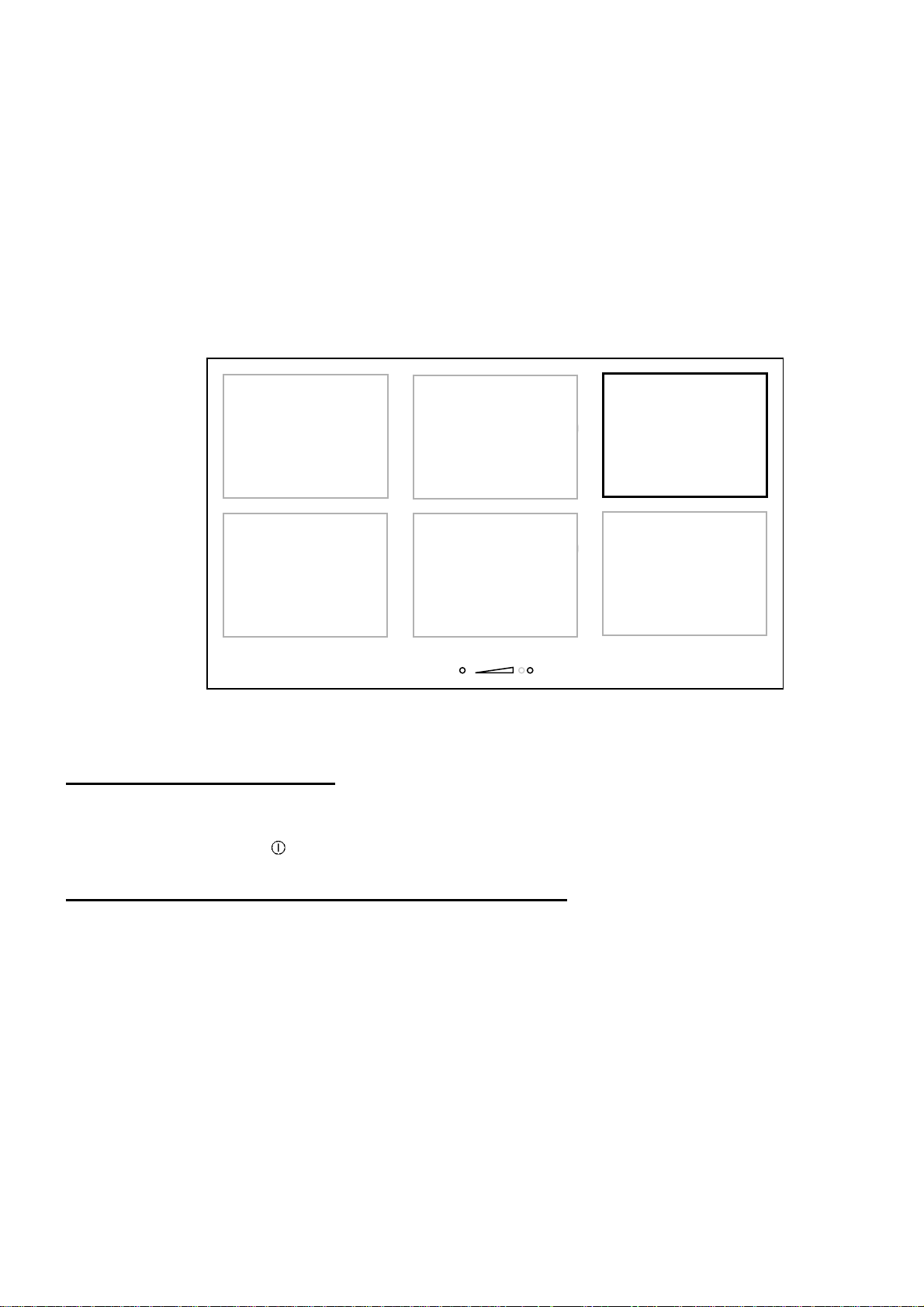
Función de prueba de velocidad del recipiente de cocción
Test zone
Con la tecnología de inducción, las cazuelas, ollas y sartenes con las que vamos a cocinar son
una parte importante para sacar el máximo partido a tu placa de coccción.
Como parte del sistema de cocción, te tienes que asegurar que el menage (cazuelas, ollas y
sartenes ) que vas a usar, te ofrece la mejor experiencia de cocina al trabajar con el mismo nivel
de rendimiento de nuestra placa de inducción.
La función de prueba de velocidad del recipiente de cocción, ofrece la posibilidad de medir la
eficiencia y la velocidad de calentamiento de tus recipientes de cocina.
El test solo se puede realizar cuando no estemos cocinando y solo en la zona especificada a
continuación.
Cada acción debe hacerse dentro de los 6 segundos posteriores a la anterior.
Pon la cazuela en la Test Zone
Pon en marcha la placa
Presiona la tecla on/off [ ]
Dentro de los primeros 6 segundos después de empezar
80

Activa la función
Presiona el slider
Mantener caliente
Presiona el slider
test
Presiona simultáneamente la tecla “Mantener caliente [ ] y sobre “SLIDER”.
[ 0 ], [ t ] se muestran.
[ 0 ] está fijado.
Presiona sobre
[ t ] parpadea.
Inicia el test
Presiona el “SLIDER”.
[ 0 ] se mueve.
[ t ] parpadea.
Test results
Por ejemplo, la cazuela en potencia 7:
Categoría
de potencia
Resultado del
81

El recipiente de cocción se clasifica en 3 categorías, con un nivel de velocidad predeterminado
Categoría
Indicación
que se muestra en el gráfico de barras.
Rendimiento de baja velocidad, el utensilio de cocina no se recomien-
Avisos importantes:
Algunos utensilios de cocina pueden tener una eficiencia tan baja que ni siquiera son detectados
por la placa, en este caso, se mostrará el símbolo [ ].
El utensilio de cocina siempre debe centrarse en la zona de prueba, un centrado incorrecto
puede causar resultados inexactos.
Los resultados se muestran durante 3 segundos en el display, después de este tiempo, la placa
se enciende automáticamente en modo normal y se puede usar para cocinar.
Ten en cuenta que el nivel de velocidad no es el único punto importante que evalúa la calidad de
los utensilios de cocina. Para asegurarse de que está perfectamente adaptado para la
inducción, consulte el capítulo "Consejos para cocinar" para obtener más detalles.
da para cocinar con inducción.
Rendimiento de velocidad media, el utensilio de cocina está adaptado
para cocinar con inducción.
Utensilio de cocina de alto rendimiento para la mejor experiencia de
cocina con inducción.
82

CONSEJOS DE COCCIÒN
Calidad de las cacerolas
Materiales adecuados: acero, acero esmaltado, fundición, inoxidable con fondo ferro-magnético,
aluminio con fondo ferro-magnético
Materiales no adecuados: aluminio e inoxidable con fondo no ferro-magnético, cobre, latón,
vidrio, cerámica, porcelana
Los fabricantes especifican si sus productos son compatibles con la inducción.
Para verificar si las cacerolas son compatibles:
• Ponga un poco de agua en una cacerola colocada sobre una zona de cocción por
inducción regulada a nivel [ 9 ]. Este agua debe calentarse en algunos segundos.
• Ponga un imán sobre el fondo externo de la cacerola; debe quedarse pegado.
Algunas cacerolas pueden hacer ruido al colocarlas sobre una zona de cocción por inducción.
Estos ruidos no representan en ningún caso un defecto en el aparato ni tienen influencia en su
funcionamiento.
Dimensión de las cacerolas
Las zonas de cocción se adaptan automáticamente a la dimensión del fondo de la cacerola,
hasta un cierto límite. Por ello, el fondo de esta cacerola debe tener un diámetro mínimo en
función del diámetro de la zona de cocción correspondiente.
Para obtener el máximo rendimiento de la placa de cocción, coloque la cacerola bien centrada
en la zona de cocción.
83
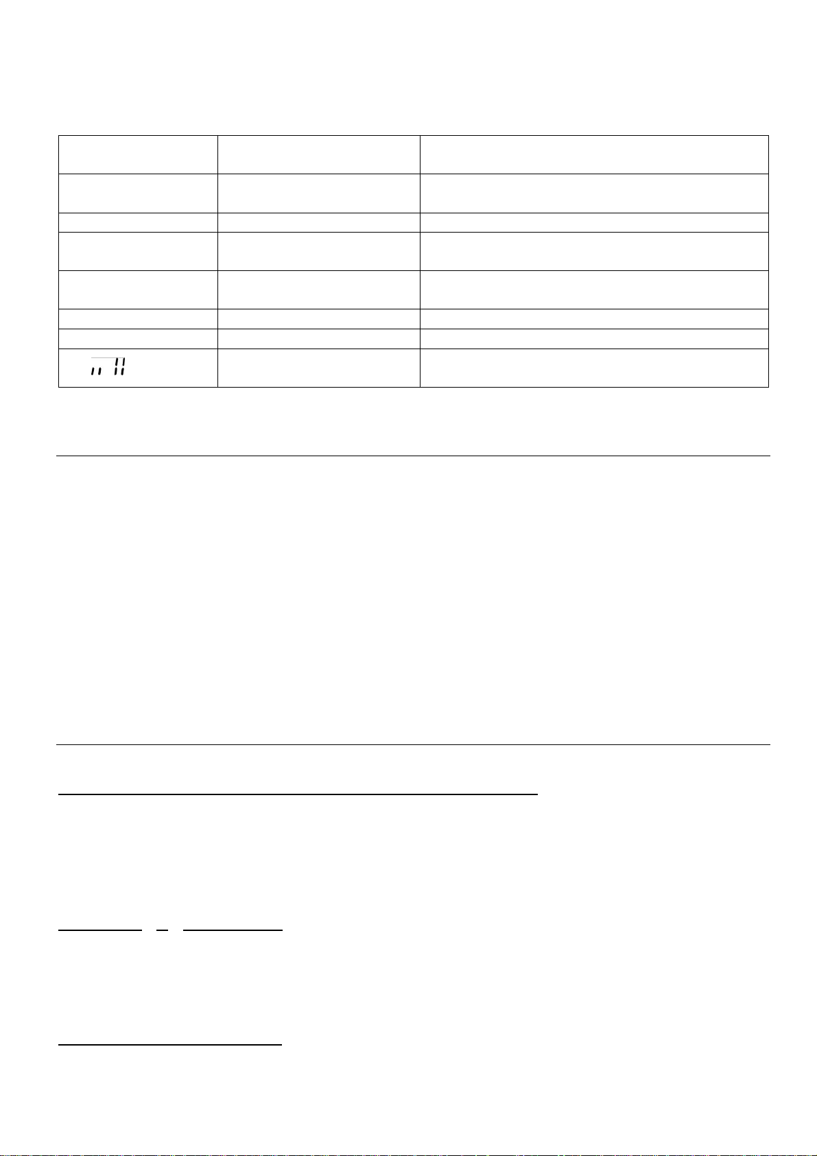
Ejemplos de ajuste de las potencias de cocción
Recalentar
Platos precocinados
Descongela
r
Legumbres, pescados, productos congelados
3 a 4
Vapor
Legumbres, pescados, carne
Legumbres frescas
Goulasch, filetes rellenos, callos
7 a 8
Cocer
,
Freír
Patatas, buñuelos, tortas
9 Freír,
llevar a ebullición
Filetes, tortillas
,
agua
Llevar a ebullición
agua
(los siguientes valores son indicativos)
1 a 2 Hacer fundir
2 a 3 Inflar
4 a 5 Agua Patatas hervidas, sopas, pastas
6 a 7 Cocer a fuego suave Carnes, hígado, huevos, salchichas
P y
Freír,
Salsas, mantequilla, chocolate, gelatina
Arroz, puddings y platos cocinados
Llevar a ebullición cantidades importantes de
CONSERVACIÓN Y LIMPIEZA
Es necesario apagar completamente el aparato para limpiarlo.
Deje enfriar el aparato, ya que hay riesgo de quemaduras.
• Limpie los restos de cocción con agua a la que haya añadido un producto lavavajillas o un
producto comercial aconsejado para vitrocerámica.
• No utilice productos de limpieza abrasivos que podrían dañar el aparato.
• Seque el aparato con un trapo limpio.
• Retire inmediatamente el azúcar o materiales que contengan azúcar.
• No utilice en ningún caso aparatos "a vapor" o "a presión".
• No utilice objetos que comporten riesgo de rayar la vitrocerámica (como estropajos
abrasivos o puntas de cuchillo…).
QUÉ HACER EN CASO DE PROBLEMA
La placa de cocción o las zonas de cocción no se encienden:
• La placa está mal conectada a la red eléctrica
• El fusible de protección ha saltado
• Verifique que no esté activado el bloqueo
• Las teclas táctiles están cubiertas de agua o de grasa
• Hay un objeto encima de las teclas táctiles
El símbolo [ U ] se enciende:
• No hay cacerola en la zona de cocción
• El recipiente utilizado no es compatible con la inducción
• El diámetro del fondo de la cacerola es demasiado pequeño respecto a la zona de
cocción
El símbolo [ E ] se enciende:
• Hay un fallo en el sistema electrónico
• Desconecte y vuelva a conectar el aparato
84
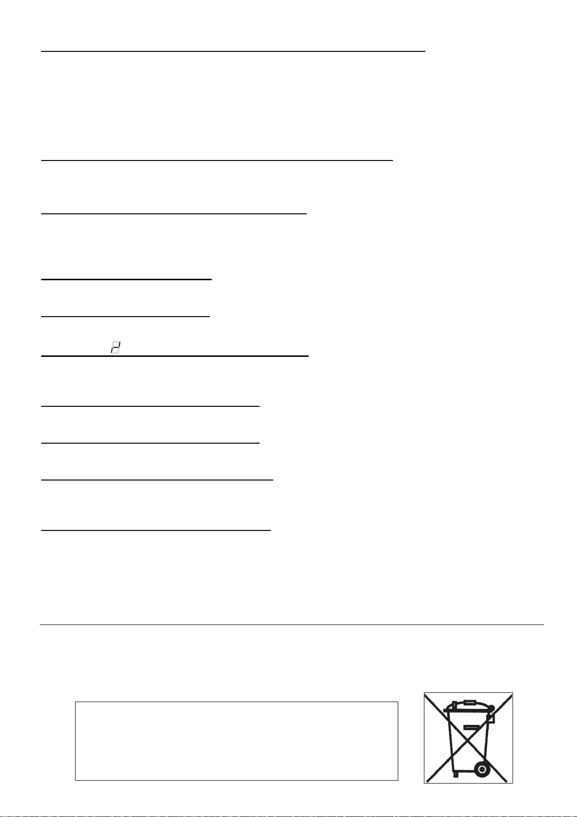
Una de las zonas o el conjunto de la placa de cocción se desconecta:
• Ha saltado la desconexión de seguridad
• Ésta se acciona en caso que haya olvidado de apagar una de las zonas de calentamiento
• Se conecta igualmente cuando una o varias teclas táctiles están tapadas
• Una de las cacerolas está vacía y su fondo se ha sobrecalentado
• La placa dispone igualmente de un dispositivo de reducción automática del nivel de
potencia y de corte automático en caso de sobrecalentamiento
La ventilación continúa funcionando después de parar la placa:
• Esto no es un fallo, el ventilador continúa protegiendo la electrónica del aparato
• La ventilación se parará automáticamente
El mando de cocción automática no se conecta:
• La zona de cocción está aún caliente [ H ]
• Está conectado el nivel máximo de cocción [ 9 ]
• El nivel de cocción se ha conectado con la tecla [ - ]
El panel de control indica [ U ]:
• Referirse al capítulo “Mantener caliente”
El panel de control indica [ II ]:
• Referirse al capítulo “Pausa”
El símbolo [ ] o [ Er03 ] aparece en la pantalla:
• • Un objeto o líquido cubre las teclas de control. El símbolo desaparece cuando la llave de
libertad o limpiar
El símbolo [ E2 ] aparece en la pantalla:
• La placa se ha sobrecalentado, deje que se enfríe y vuelva a ponerla en marcha.
El símbolo [ E8 ] aparece en la pantalla:
• Entrada de aire al ventilador obstruida, Libérela.
El símbolo [ U400 ] aparece en la pantalla:
• El aparato está mal conectado a la red. Compruebe la conexión y vuelva a poner en
marcha la placa.
El símbolo [ Er47 ] aparece en la pantalla:
• El aparato está mal conectado a la red. Compruebe la conexión y vuelva a poner en
marcha la placa.
Si uno de los símbolos anteriores persiste, llame al servicio técnico.
PROTECCIÓN DEL MEDIO AMBIENTE
• Los materiales de embalaje son ecológicos y reciclables
• Los aparatos electrónicos están formados por materiales reciclables y a veces de
materiales nocivos para el medio ambiente, pero necesarios para el buen funcionamiento
y la seguridad del aparato
•
No tirar nunca su aparato con los residuos domésticos
•
Llame al servicio de retirada de electrodomésticos o
déjelo en los lugares de depósito establecidos por su
municipio y adaptados al reciclaje de los aparatos
electrodomésticos
85

INSTRUCCIONES DE INSTALACIÓN
El montaje es competencia exclusiva de especialistas.
El usuario está obligado a respetar la legislación y las normas en vigor en su país de residencia.
Colocación de la junta de estanqueidad
La junta adhesiva suministrada con el aparato permite evitar cualquier filtración en el mueble.
Su colocación debe efectuarse con gran cuidado según el croquis adjunto.
Pegar la junta (2) sobre el reborde de la placa,
a 2 mm del borde exterior, después de haber
quitado la lámina de protección (3).
Encaje:
• La abertura en la superficie de trabajo será, según el modelo, de:
Tamanho de corte
Type Larg. Prof. Larg. Prof. Raio Larg. Prof. Espessura
P906IM3G5NE
• La distancia entre la placa de cocción y la pared debe ser de 50 mm. como mínimo.
• La placa de cocción es un aparato perteneciente a la clase de protección "Y". Cuando se
empotre, en la parte posterior y en uno de los lados puede haber una pared o un armario
alto. Pero en el otro lado no debe haber ningún mueble ni aparato que sea más alto
que la superficie de cocción
• Las placas y revestimientos de las superficies de trabajo deben ser de materiales
resistentes al calor (100°C)
• Las juntas de los bordes de la pared deben ser termo-resistentes
• Los materiales de las superficies de trabajo pueden hincharse en contacto con la
humedad. Para los cantos del corte, aplique un barniz o una cola especial.
• No instale la placa encima de un horno sin ventilación ni de un lavavajillas
• Asegure un espacio de 20 mm entre el fondo de la caja del aparato y la pared para
asegurar una buena circulación de aire para la refrigeración de la electrónica
• Si hay un cajón debajo de la superficie de cocción, evite guardar en él objetos inflamables
(por ejemplo: sprays) y objetos que no resistan el calor
• La distancia de seguridad entre la placa de cocción y la campana de aspiración situada
encima debe respetar las indicaciones del fabricante de la campana. En caso de falta de
instrucciones, respete una distancia mínima de 760 mm.
• El cable de conexión no debe estar sometido, después de la colocación, a ninguna
tensión mecánica, como la causada por un cajón
• ADVERTENCIA: Use sólo protectores de las placas fabricados por el fabricante del
electrodoméstico de cocción o en su defecto los que el mismo indique en su manual de
uso y que sean compatibles con los protectores incorporados en el aparato
electrodoméstico. El uso de protecciones inadecuadas puede causar accidentes.
750 490 886 526 8 880 520 4
Montagem embutida Tamanho do vidro
86
CONEXIÓN ELÉCTRICA
• La instalación de este aparato y su conexión a la red eléctrica sólo deben confiarse a un
electricista que esté al día de las prescripciones reglamentarias.
• La protección contra las piezas bajo tensión eléctrica debe asegurarse después del
montaje.
• Los datos necesarios para la conexión se encuentran en la placa de características y en
la placa de conexión situadas debajo del aparato.
• Este aparato debe poderse aislar del sector por medio de un dispositivo de
seccionamiento omnipolar. Cuando esté abierto (desconectado) debe asegurarse una
separación de 3 mm.
• El circuito eléctrico debe estar separado de la red por dispositivos adecuados, por ejemplo
disyuntores, fusibles, interruptores diferenciales y contactores.
• Si el aparato no esta provisto de una fiche accesible, otros medios de desconexión deben
incorporarse a la instalación fija segun las reglamentaciones de la instalación.
• El cable de alimentación debe colocarse de manera que no toca las partes calientes de la
placa de cocción.
Atención!
Este aparato está diseñado sólo para una alimentación de 230 V~ 50/60 Hz
Conecte siempre la toma de tierra de protección.
Siga el esquema de conexión.
La caja de conexión se encuentra debajo de la placa de cocción. Para abrir la tapa, utilice un
destornillador medio. Colóquelo en las 2 ranuras situadas en la parte anterior de las 2 flechas.
CONEXION EL APARATO :
Red conexión
230 V~ 50/60 Hz 1 phase +N 3 x 4 mm2
400 V~ 50/60Hz 2 phases + N 4 x 2,5 mm
400 V~ 50/60Hz 3 phases + N 5 x 1,5 mm
* calculado con el coeficiente de simultaneidad según la norma EN 60 335-2-6
Diámetro
del cable
H 05 VV - F
H 05 RR - F
H 05 VV - F
2
H 05 RR - F
H 05 VV - F
2
H 05 RR - F
Cable
Calibre de
protección
40 A *
25 A *
16 A *
87

Para los distintos tipos de conexiones, utilice los puentes de bronce que encontrará en la caja
situada al lado del terminal.
Monofase 230V~1P+N
Coloque el 1r puente entre el terminal 1 y el 2 y entre el 2 y el 3, el 2º entre el 4 y el 5.
Conecte la tierra al terminal “earth”, el neutral N al terminal 4 o 5, la Fase L a uno de los
terminales 1, 2 o 3.
Bifase 400V~2P+N
Coloque el 1r puente entre el terminal 1 y el 2, el 2º entre el 4 y el 5.
Conecte la tierra al terminal “earth”, el neutral N al terminal 4 o 5, la Fase L1 al terminal 1 o 2 y la
Fase L2 al terminal 3.
Trifase 400V~3P+N
Coloque un puente entre el terminal 4 y el 5.
Conecte la tierra al terminal “earth”, el neutral N al terminal 4 o 5, la Fase L1 al terminal 1 y la
Fase L2 al terminal 2 y la Fase L3 al terminal 3.
Atención! Introduzca bien los cables y apriete bien los tornillos.
No somos responsables de ningún incidente debido a una conexión incorrecta o que
pudiere ocurrir a causa del uso de un aparato no conectado a tierra o equipado con una
tierra defectuosa.
88


24833-0
 Loading...