

Page 1
JM.3 ESA
JM.4 ESA
L8542919
04/2011 rev 0
UNIONE NAZIONALE COSTRUTTORI
AUTOMATISMI PER CANCELLI, PORTE
SERRANDE ED AFFINI
Page 2

3
34
202
446
PTC3 3024 / PTC4 3024
PTCL4 4024
PTC3 2660 / PTC4 2660
PTCL4 3660
1
2
min. 40mm
3
2+2 M6x16
R
D
F
F
2+2 M6x16
R2
4+4 M6x16
P
P
R
D
4a
4b
Page 3
4
5
D
M
M
R
R
S
S
6
7 8
S
P
4,8x38
9 10
Page 4

5
11 12
13a
V
13b
K
PTC.4 / PTCL.4
AU.C25
M
D
Page 5

6
16
17
14
S
A
Page 6

7
18
Cavo di acciaio.
Steel cable.
Stahlkabel.
Corde en acier.
Cable de acero.
Pręt żelazny.
Guaina.
Sheath.
Hülse.
Gaine.
Guaina.
Osłona.
Registro.
Register.
Regulierung.
Réglage.
Reglaje.
Rejestr.
Staffa.
Support.
Stütze.
Support.
Soporte.
Zaczep.
Morsetto.
Clamp.
Klammer.
Étau.
Perrillo.
Zacisk.
Maniglia con piastra.
Handle with plate.
Handgriff mit Platte.
Manette avec plaque.
Manilla con placa.
Uchwyt z płytą.
Blocca.
Block.
Sperrung.
Blocage.
Bloquea.
Blokuje.
Sblocca.
Unblock.
Freigabe.
Déblocage.
Desbloquea.
Odblokowuje.
Rosetta 9x24 UNI 6593.
Washer 9x24 UNI 6593.
Scheibe 9x24 UNI 6593.
Rondelle 9x24 UNI 6593.
Arandela 9x24 UNI 6593.
Podkładka 9x24 UNI 6593.
Rosetta per M8 DIN 6798E.
Washer M8 DIN 6798E.
Scheibe M8 DIN 6798E.
Rondelle M8 DIN 6798E.
Arandela para M8 DIN 6798E.
Podkładka dla M8 DIN 6798E.
Vite M8x10 UNI 5739.
Screw M8x10 UNI 5739.
Schraube M8x10 UNI 5739.
Vis M8x10 UNI 5739.
Tornillo M8x10 UNI 5739.
Śruba M8x10 UNI 5739.
Page 7

8
19
Mettere a piombo il braccio.
Level the arm.
Arm lotrecht stellen.
Mettre à plomb le bras.
Aplomar bien el brazo.
Ustawić ramię w pozycji
pionowej.
Braccio per porte a contrappesi art. AU.C25.
Overhead doors with balanceweights: special arm art. AU.C25.
Kipptor mit Gegengewichten: Sonderarm, Teil AU.C25.
Portes basculantes à contrepoids: bras spécial art. AU.C25.
Brazo para puerta de contrapesos art. AU.C25.
Ramię dla bram z przeciwwagą art. AU.C25.
Rotaia.
Rail.
Schiene.
Morceau de rail.
Guía.
Szyna.
Pattino.
Sliding plate.
Platte.
Plaque.
Patín.
Ślizgacz.
Regolare
Adjust
Regulieren
Régler
Regulación
Regulowanie.
Vite M6x35 UNI 5931
Screw M6x35 UNI 5931
Schraube M6x35 UNI 5931
Vis M6x35 UNI 5931
Tornillo M6x35 UNI 5931
Śruba M6x35 UNI 5931.
A porta chiusa lasciare 2 ÷ 3 cm.
Keep a distance of 2 ÷ 3 cm when the door is closed.
Wenn die Tür geschlossen ist, lassen 2 ÷ 3 cm.
Il faut lasser 2 ÷ 3 cm quand la porte est ouvert.
Cuando la puerta ésta cerrada, hay que haber 2 ÷ 3 cm.
Podczas zamkniętej bramy pozostawić 2 ÷ 3 cm.
Fissare il braccio sul filo superiore della porta.
Fix the arm to the top edge of the door.
Arm an der oberen Kante des Tores befestigen
Fixer le bras sur l’arête supérieure de la porte.
Fijar el brazo en la arista superior de la puerta.
Przymocować ramię do górnego prętu bramy.
Page 8

12
EC Declaration of Conformity
Directive 2004/108/EC(EMC); 2006/95/EC (LVD)
Manufacturer:
Automatismi Benincà SpA.
Address:
Via Capitello, 45 - 36066 Sandrigo (VI) – Italy
It is hereby stated that the product
pulling automatic system for sectional doors model
JM.3 ESA/JM.4 ESA.
is compliant with provisions set forth in the following EC Directives:
- DIRECTIVE 2004/108/EC OF THE EUROPEAN PARLIAMENT AND OF THE COUNCIL of 15 December 2004, on the harmonisation of the laws of Member States relating to electromagnetic compatibility and which cancels Directive 89/336/EEC, according to the following
harmonised regulations: EN 61000-6-2:2005, EN 61000-6-3:2007.
- DIRECTIVE 2006/95/EC OF THE EUROPEAN PARLIAMENT AND OF THE COUNCIL of 12 December 2006, on the harmonisation
of the laws of Member States relating to electrical equipment designed for use with certain voltage limits, according to the following harmonised
regulations: EN 60335-1:2002 + A1:2004 + A11:2004 + A12:2006 + A2:2006 + A13:2008; EN 60335-2-103:2003.
- DIRECTIVE 2006/42/EC OF THE EUROPEAN PARLIAMENT AND OF THE COUNCIL of 17 May 2006, on machinery, which amends
Directive 95/16/EC, and complies with the requisites for the “partly completed machinery (almost machinery)” set forth in the EN13241-1:2003
regulation.
• Moreover, Automatismi Benincà SpA declares that the pertaining technical documentation has been drawn up in compliance with Attach-
ment VII B of the 2006/42/ EC Directive and that the following requirements have been complied with: 1.1.1 - 1.1.2 - 1.1.3 - 1.1.5 - 1.2.1 - 1.2.3
- 1.2.6 - 1.3.1 - 1.3.2 - 1.3.3 - 1.3.4 - 1.3.7 - 1.3.9 - 1.5.1 - 1.5.2 - 1.5.4 - 1.5.5 - 1.5.6 - 1.5.7 - 1.5.8 - 1.5.10 - 1.5.11 - 1.5.13 - 1.6.1 - 1.6.2 - 1.6.4
- 1.7.2 - 1.7.4 - 1.7.4.1 - 1.7.4.2 - 1.7.4.3.
• The manufacturer undertakes that information on the “partly completed machinery” will be sent to domestic authorities. Transmission ways
are also included in the undertaking, and the Manufacturer’s intellectual property rights of the “almost machinery” are respected.
• It is highlighted that commissioning of the “partly completed machinery” shall not be provided until the final machinery, in which it should
be incorporated, is declared compliant, if applicable, with provisions set forth in the Directive 2006/42/EC on Machinery.
• Moreover, the product, as applicable, is compliant with the following regulations:
EN 12445:2002, EN 12453:2002, EN 12978:2003.
Benincà Luigi, Legal Officer.
Sandrigo, 22 November 2010.
The product shall not be used for purposes or in ways
other than those for which the product is intended for and
as described in this manual. Incorrect uses can damage
the product and cause injuries and damages.
The company shall not be deemed responsible for the
non-compliance with a good manufacture technique of
gates as well as for any deformation, which might occur
during use.
Keep this manual for further use.
Qualified personnel, in compliance with regulations in force,
shall install the system.
Packaging must be kept out of reach of children, as it can
be hazardous. For disposal, packaging must be divided
the various types of waste (e.g. carton board, polystyrene)
in compliance with regulations in force.
The installer must supply all information on the automatic,
manual and emergency operation of the automatic system
and supply the end user with instructions for use.
WARNING
;
An omnipolar switch/section switch with remote
contact opening equal to, or higher than 3mm
must be provided on the power supply mains..
Make sure that before wiring an adequate differential
switch and an overcurrent protection is provided.
Pursuant to safety regulations in force, some types of installation require that the gate connection be earthed.
During installation, maintenance and repair, cut off power
supply before accessing to live parts.
Descriptions and figures in this manual are not binding.
While leaving the essential characteristics of the product
unchanged, the manufacturer reserves the right to modify
the same under the technical, design or commercial point
of view without necessarily update this manual.
Page 9

13
Introduction
Thank you for choosing our JM.3 ESA/JM.4 ESA ratiomotor.
All items in the wide Benincà production range are the result
of twenty-years’ experience in the automatism sector and
of continuous research for new materials and advanced
technologies.
We are, therefore, in the position to offer highly reliable
products that due to their power, effectiveness and useful
life, fully satisfy the final user’s requirements.
All our products are covered by warranty.
Possible injury to people or accidents caused by defects in
construction are covered by a civil liability policy drawn up
with one of the major insurance companies.
1. General information
The system has been studied to motorize sectional doors.
To be applied onto balancing doors, a special fitting arm is
required (item AU.C25).
In any case, following conditions will have to be observed:
- the distance between the door highest point and the ceiling
must be at least 40mm (fig. 2).
- it has to be possible to open and close the door by pulling
and pushing horizontally its top edge (fig.2).
- manual moves must be smooth and regular.
The gear motor is available in two versions:
JM.3 ESA (600Nm) and JM.4 ESA (1200Nm) to which the
following tracks can be matched (fig.1):
PTC.3: Pre-assembled track, with 8 mm belt, 2.5m max
height, for JM.3 ESA only
PTC.4: Pre-assembled track, with 10 mm belt, for doors with
2.5 m max height, for JM.3 ESA and JM.4 ESA
PTC.L4: Pre-assembled track, with 10mm belt, for doors with
3.5 m max height, for JM.3 ESA and JM.4 ESA
Technical data JM.3 ESA JM.4 ESA
Feed
Motor feed
Absorbed rating
Drive speed
Drive/thrust force
Degree of protection
Jogging
Operating temp.
Noise level
Max. door height:
with PTC3/PTC4
with PTCL4
Power unit weight
Total weight:
with PTC3/PTC4
with PTCL4
230Vac
24Vdc
150W
8,9 m/min
600N
IP40
Intensive Use
-20°C/+70°C
<70dB (A)
2,5m
3,5m
6,2 kg
11,8kg
13,6kg
230Vac
24Vdc
315W
8,9 m/min
1200N
IP40
Intensive USe
-20°C/+70°C
<70dB (A)
2,5m
3,5m
7,6 kg
13kg
15kg
2. Installation
a) Place the track on a flat surface and lay it as shown in
Fig.3
b) Referring to Fig. 4, align both ends of the tracks and fit
them with the two plates P, by using the eight M6X16
screws, the nuts D and the washers R.
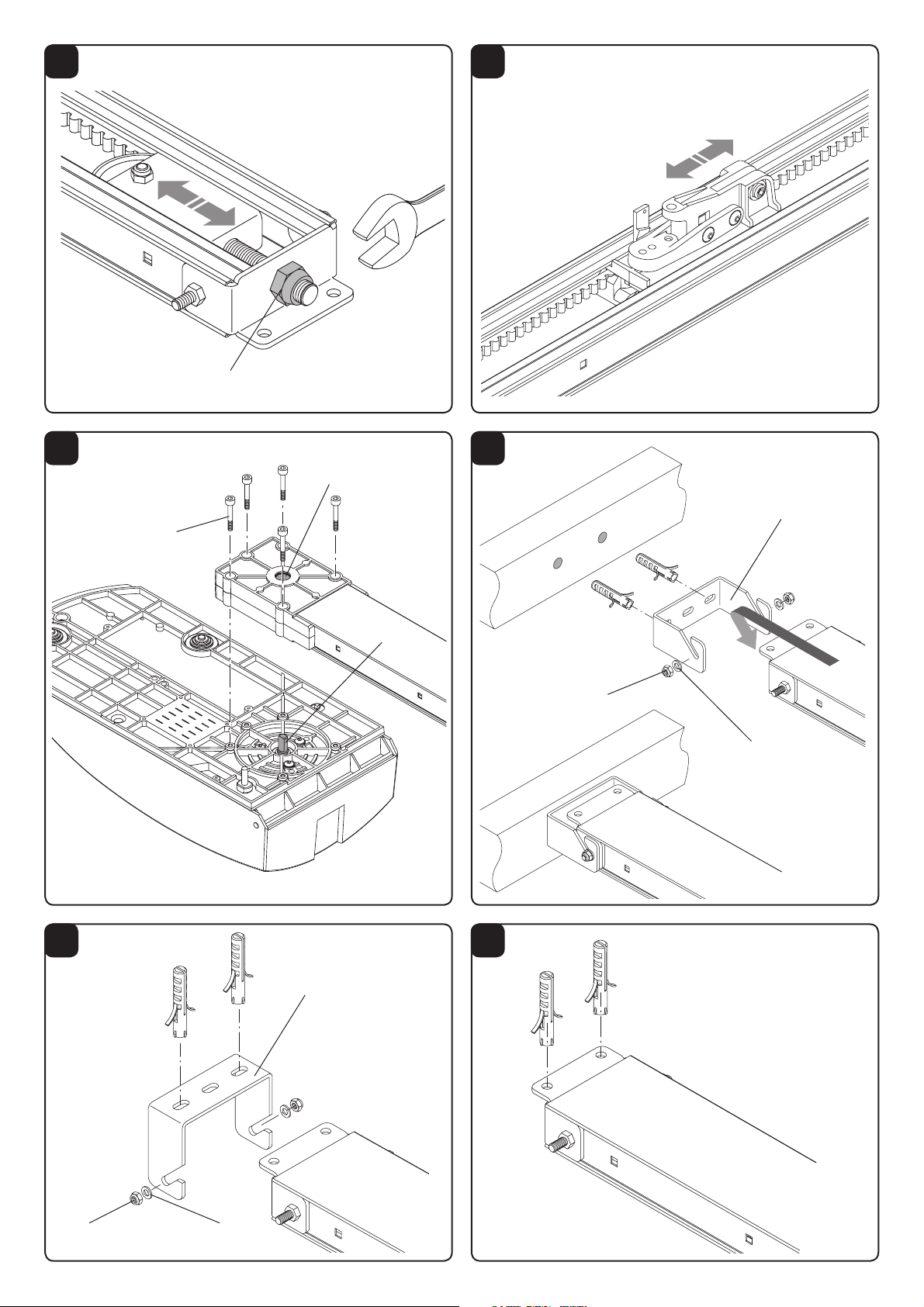
c) Make sure that the belt is correctly tensioned. If necessary,
it can be adjusted through nut D, as shown in Fig.5.
The correctly tensioned belt keeps its position along the
entire track, without bending, but still resilient at a slight
pressure by hand.
d) Move the drive carrier (Fig.6) until the pulley housing (ref.
S of Fig. 7) touches the motor shaft pin (ref. P of Fig. 7)
e) Fix the track to the basis of the gear motor, as per Fig.7.
Fit the track to the basis of the gear motor, with the five
D4,8x38 screws.
f) Fit the hooking bracket S to wall (Fig.8) or ceiling (Fig.9).
Mark the two fitting points corresponding to the centre of
the door. Hook the track to the bracket and fix it by means
of nuts M and washers R. Rest the gear motor body on
the floor.
If there is not enough space to use the bracket S, the track
can be fixed directly to the ceiling through the holes shown
in Fig.10.
g) Position the fitting brackets to ceiling by means of the
special housings in the track, near the gear motor (Fig.11)
and fix them by means of screws M and nuts D. Two fitting
brackets for mounting to ceiling are supplied with PTC.4
and PTC.L4 tracks. They must be fitted near the joining
point of the tracks.
h) By using a ladder, hoist the gear motor (Fig.12), mark the
fitting points of the brackets, drill the holes and fix the gear
motor by means of screws and screw anchors suited to
the material.
i) temporarily fix the opening and closing mechanical stop-
pers, at beginning and end of track, by using the screws
K, as highlighted in Fig.13a. At the end of the adjustment
phase of the automatic system, the stoppers will be positioned more precisely and firmly fixed to the track between
the 2 screws X, while drilling two holes, as indicated in Fig.
13b.
Note: while making the holes, take care not to drill the stoppers as
well.
l) Connect the driving rod A to the drive slide by means
of the M6x20 cylinder head screws and the self-tapping
nut. The rod movement should not be obstructed. Fix the
bracket S to the door so that, with closed door, the rod A
is in an almost vertical position. Shorten the drive rod A,
if required.
In the event of heavy doors, it is recommended to use both
upper and front holes.
m) Insert the cord in the release lever and in the knob. Make
a knot as indicated in the detail of Fig.14.
n) Apply the warning sticker supplied to the door:
3. How to store the opening and closing positions in
memory
The gear motor is equipped with a control unit with a memorisation function of the opening and closing positions. The
memorisation procedure is described in instructions supplied
with the control unit and requires the positioning of the mechanical stoppers, cf. Fig.13.
4. Speed adjustment
The door speed is controlled by the control unit. Please refer
to special instructions.
WARNING!: The adjustment of the door movement
speed affects the safety level of the automatic system.
Comply with regulations in force.
Page 10

14
5. Accessories (optional)
JM.CB Emergency Battery Kit:
It permits the operation of the automatic system in the event
of power failure.
The kit is composed of: battery charge card, 2 batteries at
12V, fitting bracket, screws and cables.
The batteries must be installed on the upper part of the gear
motor basis, as per Fig.16.
To connect batteries, please refer to specific instructions.
Note: Once installed, the batteries protrude from the track
upper profile by approx. 10mm.
JM.PP Cord Manual Control:
It permits the control of the automatic system from indoor by
means of a cord, thus avoiding the installation of a keyboard.
The kit is composed of: micro-switch group, cord control with
knob, spring and cables (Fig.16)
For the installation, please refer to specific instructions.
Fig.17 shows the cord in working position.
6. Manual operation from outdoor
In sectional doors, the system can be released also from
outdoor by using item JM.SF (Fig.18).
A. Insert the metal cable in the slide, as indicated in Figure
18.
B. Fit the adjuster on the bracket and insert the sheath.
C. Fix the other end of the cable to the release device. The
figure shows an example of connection to the garage door
handle AU.MS.
N.B.: Any type of cord release device can be used under
the condition that the release stroke is of at least 15
mm.
If the device is able to keep the lever in the release position
(e.g. AU.MS) it would be easier to cut the hooking lever, as
shown in the detail of Fig. 18. In this way, by moving the
handle in the original position, the automatic operation is
reset.
7. Assembling onto balancing doors
Overhead door with balanceweights (fig.19): these doors
need the special arm art. AU.C25.
In order to assemble it make sure that:
tUIFBSNJTmYFEUPUIFUPQFEHFPGUIFEPPS
tUIFBSNJTMFWFMMFE
CAUTION
The civil liability policy, which covers possible injuries to people or accidents caused by defects in construction, requires
to use original Benincà accessories.
Page 11

29
4
7
5
9
6
8
10
1
2
2
3
Ref. Denominazione - Description - Bezeichnung - Dénomination - Denominación - Określenie
JIM 3
ESA
JIM 4
ESA
1 Tendicinghia Belt tightening Riemenspanner Tendeur de cour. Tensor correa Naciągacz pasa
9686670
2
3PUBJB15$Rail PTC.3/4 Schiene PTC.3/4 Rail PTC.3/4 (VÓB15$Szyna PTC.3/4
9686671
3PUBJB15$-Rail PTC.L4 Schiene PTC.L4 Rail PTC.L4 (VÓB15$-Szyna PTC.L4
9686672
3 Carro trascinam. Drive trolley Mitnehmerwagen Chariot d'entr. 1BUÓOEFUSBDDJØOWóżek ciągnący
4 Carter Guard Gehäuse Carter Tapa Karter
5 Base Basis Basis Base Base Podstawa
9686680
6 Trasformatore Transformer Transformator Transformateur Trasformador Transformator
9686826
7 .PUPSFMotor Motor Moteur .PUPSSilnik
9686676 9686677
8 $1+&4"CP.J4 ESA CP.J4 ESA CP.J4 ESA $1+&4"CP.J4 ESA
9686825
9 4VQQPSUP3PUBJBTrack Support Schienenhalterung Support Rail 4PQPSUF3JFMWspornik szyny
9686681
10
$JOHIJB15$Belt PTC.3 (8) Riemen PTC.3 (8) Courroie PTC.3 (8) $PSSFB15$Pas PTC.3 (8)
9686682 /"
$JOHIJB15$Belt PTC.4 (10) Riemen PTC.4 (10) Courroie PTC.4 (10) $PSSFB15$Pas PTC.4 (10)
$JOHIJB15$-Belt PTCL.4 (10) Riemen PTCL.4 (10) Courroie PTCL.4 (10) $PSSFB15$-Pas PTCL.4 (10)
 Loading...