

Beninca Bullock User Manual
L8542771 ITA/ENG/FRA/ESP
09/2013 rev 5
BULLOCK 424
BULLOCK 424 115
UNIONE NAZIONALE COSTRUTTORI
AUTOMATISMI PER CANCELLI, PORTE
SERRANDE ED AFFINI
12
EC Declaration of Conformity
Directive 2004/108/EC(EMC); 2006/95/EC (LVD)
Manufacturer:
Automatismi Benincà SpA.
Address:
Via Capitello, 45 - 36066 Sandrigo (VI) – Italy
It is hereby stated that the product
automatic system 24Vdc for sliding gates
BULLOCK 424.
is compliant with provisions set forth in the following EC Directives:
- DIRECTIVE 2004/108/EC OF THE EUROPEAN PARLIAMENT AND OF THE COUNCIL of 15 December 2004, on the harmonisation of the laws of Member States relating to electromagnetic compatibility and which cancels Directive 89/336/EEC, according to the following
harmonised regulations: EN 61000-6-2:2005, EN 61000-6-3:2007.
- DIRECTIVE 2006/95/EC OF THE EUROPEAN PARLIAMENT AND OF THE COUNCIL of 12 December 2006, on the harmonisation
of the laws of Member States relating to electrical equipment designed for use with certain voltage limits, according to the following harmonised
regulations: EN 60335-1:2002 + A1:2004 + A11:2004 + A12:2006 + A2:2006 + A13:2008; EN 60335-2-103:2003.
- DIRECTIVE 2006/42/EC OF THE EUROPEAN PARLIAMENT AND OF THE COUNCIL of 17 May 2006, on machinery, which amends
Directive 95/16/EC, and complies with the requisites for the “partly completed machinery (almost machinery)” set forth in the EN13241-1:2003
regulation.
• Moreover, Automatismi Benincà SpA declares that the pertaining technical documentation has been drawn up in compliance with Attachment VII B of the 2006/42/ EC Directive and that the following requirements have been complied with: 1.1.1 - 1.1.2 - 1.1.3 - 1.1.5 - 1.2.1 - 1.2.3
- 1.2.6 - 1.3.1 - 1.3.2 - 1.3.3 - 1.3.4 - 1.3.7 - 1.3.9 - 1.5.1 - 1.5.2 - 1.5.4 - 1.5.5 - 1.5.6 - 1.5.7 - 1.5.8 - 1.5.10 - 1.5.11 - 1.5.13 - 1.6.1 - 1.6.2 - 1.6.4
- 1.7.2 - 1.7.4 - 1.7.4.1 - 1.7.4.2 - 1.7.4.3.
• The manufacturer undertakes that information on the “partly completed machinery” will be sent to domestic authorities. Transmission ways
are also included in the undertaking, and the Manufacturer’s intellectual property rights of the “almost machinery” are respected.
• It is highlighted that commissioning of the “partly completed machinery” shall not be provided until the ¿nal machinery, in which it should
be incorporated, is declared compliant, if applicable, with provisions set forth in the Directive 2006/42/EC on Machinery.
• Moreover, the product, as applicable, is compliant with the following regulations:
EN 12445:2002, EN 12453:2002, EN 12978:2003.
Benincà Luigi, Legal 2f¿cer.
Sandrigo, 22 November 2010.
The product shall not be used for purposes or in ways
other than those for which the product is intended for and
as described in this manual. Incorrect uses can damage
the product and cause injuries and damages.
The company shall not be deemed responsible for the
non-compliance with a good manufacture technique of
gates as well as for any deformation, which might occur
during use.
Keep this manual for further use.
Qualified personnel, in compliance with regulations in force,
shall install the system.
Packaging must be kept out of reach of children, as it can
be hazardous. For disposal, packaging must be divided
the various types of waste (e.g. carton board, polystyrene)
in compliance with regulations in force.
The installer must supply all information on the automatic,
manual and emergency operation of the automatic system
and supply the end user with instructions for use.
WARNING
An omnipolar switch/section switch with remote
contact opening equal to, or higher than 3mm
must be provided on the power supply mains..
Make sure that before wiring an adequate differential
switch and an overcurrent protection is provided.
Pursuant to safety regulations in force, some types of installation require that the gate connection be earthed.
During installation, maintenance and repair, cut off power
supply before accessing to live parts.
Descriptions and figures in this manual are not binding.
While leaving the essential characteristics of the product
unchanged, the manufacturer reserves the right to modify
the same under the technical, design or commercial point
of view without necessarily update this manual.
13
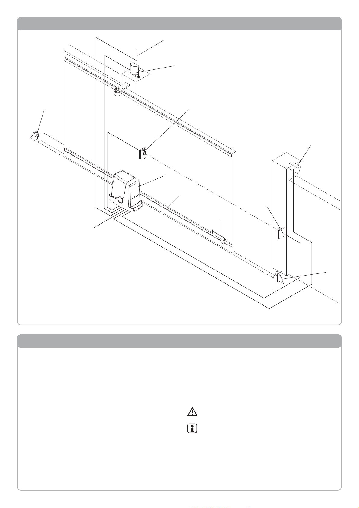
Description of the automation
8
7
4
1
2
3
3 x 1,5 min
2 x 1,5
RG 58
5
4 x 0,35
115/230V
4
6
5
2 x 0,35
3 x 0,35
H
Key of components:
1 Gear motor with incorporated control unit BULLOCK
2 M4 rack, Nylon/Fe
3 Limit switch brackets
4 Photocells
5 Mechanical stoppers
6 Key selector or digital keyboard
7 Flashing light
8 Antenna
Preliminary check
It is indispensable to carry out several checks before
starting installation:
• Try and open the gate manually, it must move without
effort and without points of resistance for the entire
run.
• When left in any intermediate position the gate must
not move.
• The leaf must be suitable for fixing to the rack (see
dimensions and limits of use).
• The guides and components subject to wear must be
in perfect working condition. If this is not the case,
replace the faulty parts.
• Check the stop retainers, controlling their efficiency
also if the leaf should arrive with force on the profile.
• The fixing area of the gear motor must not be subject
to water stagnation or flooding. If this is possible,
envision a raised installation position.
• The door structure must be strong and rigid.
• The electric set-ups necessary for installation are highlighted in the “Electric connections” paragraph. If they
are not pre-existing they must be realised, with the aid
of a specialised technician, if necessary (electrician).
• With reference to Fig. 3, check the maximum and
minimum clearances indicated in measurements A
and B.
The reliability and safety of the automation depend on the state of the door structure.
Check that there is enough space for installation
of the operator in safe and comfortable conditions.
14
Technical Data, dimensions and limits of use
TECHNICAL DATA BULLOCK
Control unit power supply 230 Vac (Bullock 424)
115 Vac (Bullock 424 115)
50/60 Hz
Motor power supply 24Vdc
Absorbed power 80 W
Absorption 0,6 A
Torque 9 Nm
Operative intermittence 10 minutes ON
50 minutes OFF
Opening speed 10 m/1'
Protection rating IP44
Functioning temperature -20°C / +60°C
Driving gear for rack M4 Z14
Noise <70 dB
Weight 6,8 kg
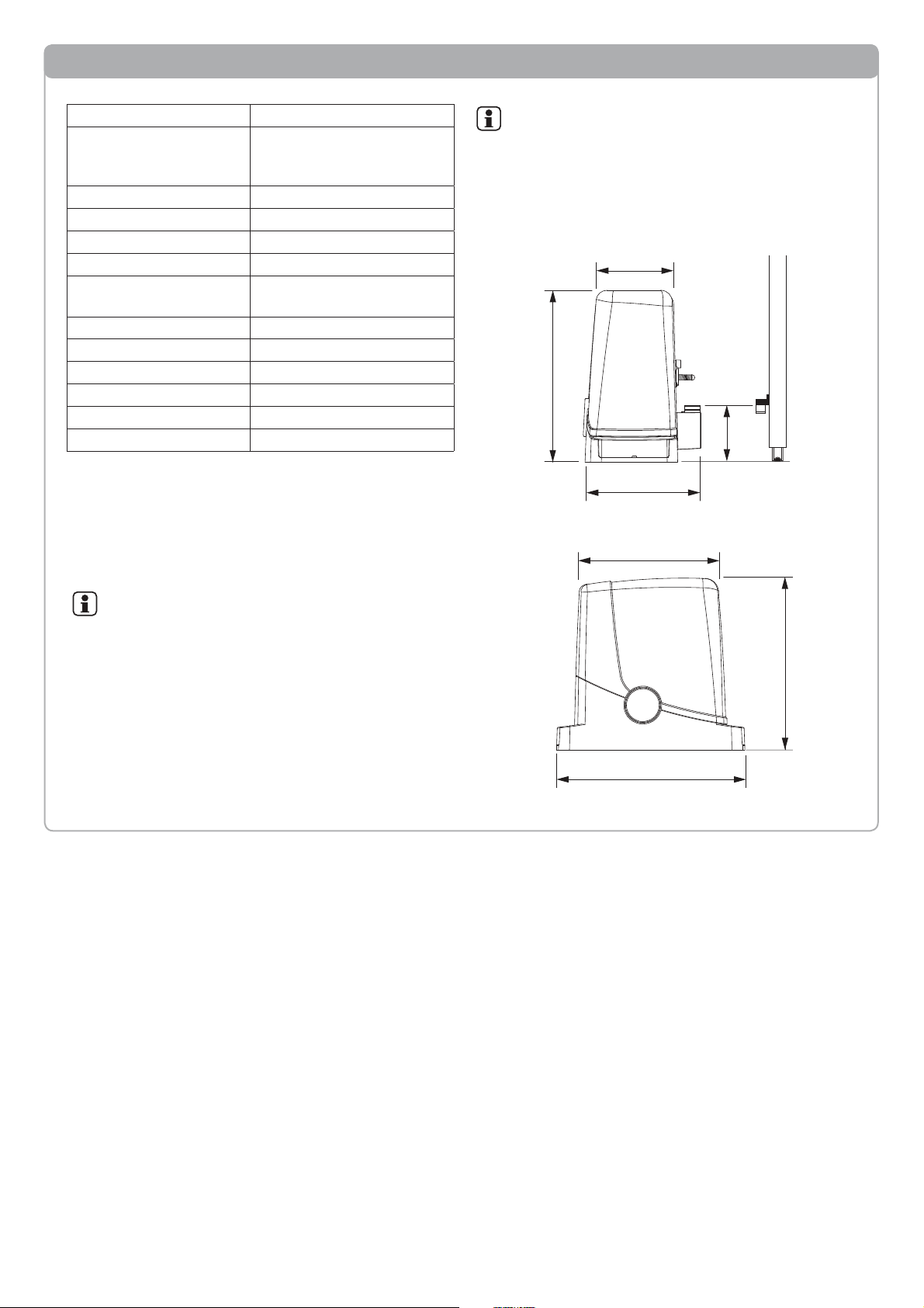
DIMENSIONS
Fig. 1 indicates the main clearance dimensions of the gear motor
complete with guide.
The measurements are expressed in millimetres.
If the rack is already present on the gate, it is important to
consider the measurement of the driving gear (89mm), for the
correct coupling between the rack and the driving gear.
If the rack is already present, check that it is well-fixed,
in good state, perfectly horizontal and that the pitch
corresponds to that of the driving gear, M4, i.e. about
12 mm between one notch and the next.
LIMITS OF USE
BULLOCK can be used exclusively for residential sliding gates
with a maximum weight of 400 kg.
Should the gate leaf be heavier than 300 kg, it is recommended
that the braking function be disabled (TSM=0) and the torque
be at its maximum value (PM=0).
The length of the leaf is not a restriction. In all cases it is recommended to install BULLOCK on leaves with length exceeding 6m.
The materials with which the door is built, the
state of maintenance and particular conditions
of use can reduce the values indicated.
In no case can the installation of BULLOCK be
considered a solution for opening inefficient
doors.
295
270
215
Fig.1
120
270
185
89
 Loading...