

Page 1
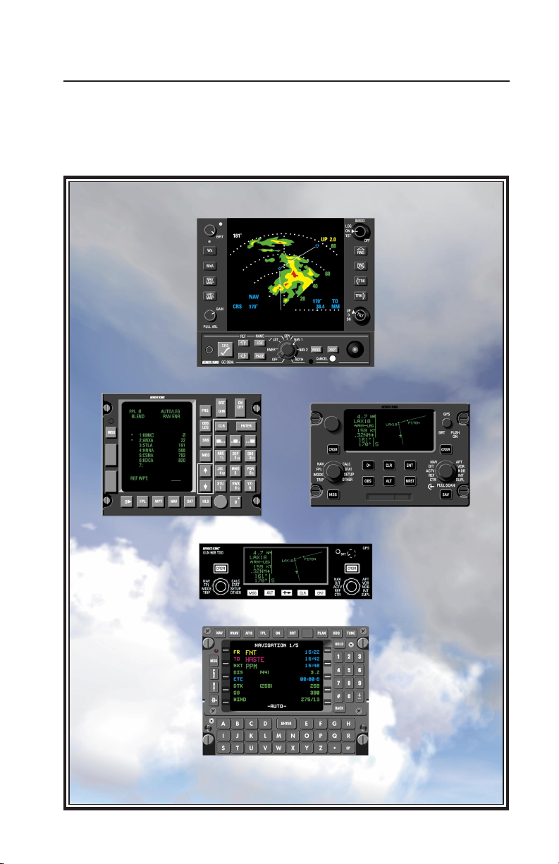
GC 360A
Radar Graphics Interface for Weather Radar
and KNS 660, KLN 88, KLN 90,
KLN 90B, KLN 900, and GNS XLS
Pilot’s Guide
Page 2

1
TABLE OF CONTENTS
Introduction . . . . . . . . . . . . . . . . . . . . . . . . . . . . . . . . . .2
Systems Compatibility . . . . . . . . . . . . . . . . . . . . . . . . . . .3
Modes and Functions . . . . . . . . . . . . . . . . . . . . . . . . . . . .4
Basic Operation . . . . . . . . . . . . . . . . . . . . . . . . . . . . . . . .7
Navigation Graphics . . . . . . . . . . . . . . . . . . . . . . . . . . . . .8
Graphics from a Single NAV . . . . . . . . . . . .9
Dual NAV Operations . . . . . . . . . . . . . . . .10
Navigation Functions . . . . . . . . . . . . . . . . .11
Radar Graphics on a Sample Flight . . . . .14
Running Checklists . . . . . . . . . . . . . . . . . . . . . . . . . . . . .18
Activating/Executing Checklists . . . . . . . . .19
If You Get Interrupted . . . . . . . . . . . . . . . .20
Programming . . . . . . . . . . . . . . . . . . . . . . . . . . . . . . . . .21
Writing Checklists . . . . . . . . . . . . . . . . . . .22
Deleting Text . . . . . . . . . . . . . . . . . . . . . . .23
Special Functions . . . . . . . . . . . . . . . . . . .24
Specifications . . . . . . . . . . . . . . . . . . . . . . . . . . . . . . . . .24
Page 3

Designed to be a powerful navigation tool, the Bendix GC 360A
Radar Graphics Unit generates a
moving-map display on your weather radar indicator, showing your
position with respect to the flightplanned course and waypoints,
nearby airports and navaids, and, of
course, weather. It continuously
updates the graphic picture of your
aircraft’s position over the ground,
making it easy to visualize the precise navigation situation.
During flight the GC 360A allows
you create new waypoints directly
on the radar screen, incorporating
them into the flight plan with the
LNAV. Course deviations due to
weather or ATC requests can
become easier to fly with positive
course guidance provided by the
GC 360A’s joystick-controlled, waypoint feature.
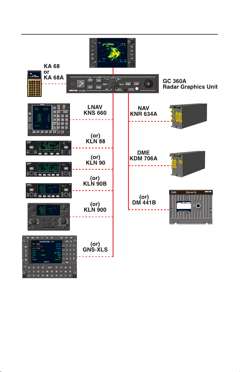
The radar graphics unit is compatible with dual LNAV or with a single
LNAV as Nav 1 and a King Gold
Crown KNR 634A Nav/KDM 706A
or DM 441B DME combination as
Nav 2. It can generate radar displays for a variety of information
computed by the LNAV, including
locations of waypoints in the flight
plan, course lines, nearby airports
and navaids, and real-time wind
data. Interfaced with a KNR 634A
Nav/KDM 706A or DM 441B DME
combination, the GC 360A can display secondary navaid position and
radial guidance graphics in the Nav
2 and BOTH modes.
By presenting navigation informa-
tion in a simple and clear format,
the GC 360A can help you determine solutions to navigation problems you otherwise might not see,
providing a valuable complement to
any Bendix RDS 81, 82, 84, 86,
ART 2000 or 2100 weather
radar/King KNS 660, KLN 88, KLN
90, KLN 90B, KLN 900 or GNS XLS
installation.
The GC 360A also provides checklist features that enable you to run
normal and emergency checklists
on your weather radar indicator.
The graphics unit’s nonvolatile
memory contains room for 935 lines
of information, generally enough for
any aircraft’s entire checklist library
plus tables of information such as
emergency or best-performance
airspeeds and aircraft weight-andbalance. During checklist operation
its color coding systems helps you
keep track of checked and
unchecked items, providing status
markers for when you need to leave
the checklist to operate the GC
360A temporarily in any other
mode.
This GC 360A Pilot’s Guide is
designed to acquaint you with the
radar graphics unit’s functions and
controls and to show ways to use it
as a navigation tool. After reviewing
this Guide and practicing radar
graphics operations in your aircraft
for a little while, you should begin to
have an understanding of how to
use the GC 360A to its best advantage, giving you the maximum
return on your investment in
AlliedSignal avionics.
2
INTRODUCTION
Page 4
3
Bendix RDS 81, 82, 84, 86,
ART 2000 or 2100
Weather Radar Indicator
SYSTEM COMPATIBILITY
This GC 360A Pilot’s Guide
assumes that the operator is
already proficient in basic operation
of the Long Range Navigation
System and weather radar. If not,
refer to their respective Pilot’s
Guides for operating instructions.
The navigation information presented by the GC 360A is not to be
used for primary navigation.
Contents of the checklists are the
responsibility of the user/installer.
Page 5
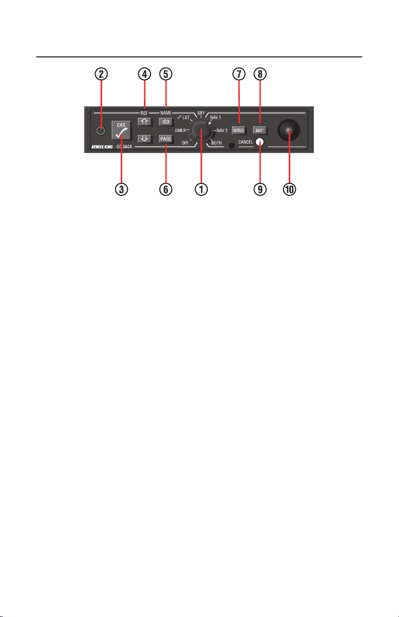
(1) MODE SELECTOR
Activates any of the GC 360A’s six
modes of operation. With the mode
selector in the OFF position, the
radar graphics unit is inoperative.
The radar is capable of displaying
weather/ground surveillance information only.
Selecting either √LSTor EMER prepares the GC 360A to run aircraft
checklists programmed with the KA
68 or KA 68A Pocket Terminal (see
Programming, page 21). When you
select a checklist mode, with the
weather radar operating in Standby ,
the GC 360A displays the appropriate Index page and assigns checklist functions to the five pushbutton
controls on the left half of the faceplate.
While programming checklist information with the Pocket Terminal,
use the mode selector to store
checklists in either the normal or
emergency checklist memory.
Select the Standby mode to erase
all Nav graphics temporarily from
the screen whenever you want an
unobstructed view of the weather
ahead. You may also select
Standby prior to aircraft shutdown
and remove power from the GC
360A with the avionics master
switch.
Activate any of the three navigation
modes to display navigation graphics on the radar screen. These
modes also assign navigation functions to all controls on the radar
graphics unit’s faceplate. The GC
360A must be interfaced to either a
LNAV or a KNR 634A navigation
receiver and a KDM 706A/DM 441B
DME as Nav 2 to generate graphics
in the Nav 2 or BOTH modes.
(2) KA 68 PHONE PLUG
RECEPTACLE
Used during programming only, to
connect the Pocket Terminal to the
GC 360A.
4
MODES AND FUNCTIONS
Page 6

(3) CURSOR CHECK-OFF KEY
In any navigation mode, the checkoff key has two primary functions.
During normal course plotting, it
alternately removes and replaces
the course line on the radar screen.
The waypoints, though, remain in
view continuously . When establish ing a temporary waypoint with the
joystick, pressing the check-off key
“freezes” its lat/lon coordinates,
transferring them to the LNAV’s
waypoint data page, allowing you to
insert it in your flight plan.
With the GC 360A in a checklist
mode, pressing the check-off key
activates the line item highlighted
by the cursor. If an index page is
displayed, operating the check-off
key will call to the screen the highlighted checklist. If a checklist page
is on the screen, the key will check
off the highlighted item, changing its
color code to green, and reposition
the cursor on the next unchecked
line item.
(4) CURSOR POSITION /
REFERENCE KEYS
Reposition the cursor up or down,
without altering line item color
codes, in checklist modes. You
may select checklists to run or pass
over line items without checking
them off.
It’s helpful to think of the cursor as a
“circular” function, with one offscreen position. In some cases you
can reference a line item more
quickly by moving the cursor up
past the top of a checklist to the
opposite end.
Upon reaching the bottom of a list,
pressing the cursor down key
removes the yellow highlight from
the radar screen. Pressing it again
causes the cursor to reappear, at
the top of the first page of the
checklist in use. You may also
remove the cursor from the radar
screen from the top of a checklist
and have it reappear at the bottom
by using the cursor up key.
The reference function is available
in any navigation mode, and
enables the radar graphics unit to
display nearby DME-equipped
navaids (Vortacs, VOR/DME’s,
Tacans) whose position is currently
being monitored by the LNAV. It
can distinguish between high-altitude, low-altitude and terminal
navaids.
(5) INDEX/NAME KEY
Displays the appropriate index
page on the radar indicator in either
checklist mode, with the cursor
highlighting the checklist currently
in use. Pressing the IDX key also
restores the checklist in use to its
original, unchecked form.
The name function is available in
the navigation modes. It alternately
removes and displays the names of
all waypoints on the radar screen.
Waypoint numbers, though, appear
continuously with a KNS 660, KLN
88 or KLN 90 interface. Waypoint
numbers will not be displayed with a
KLN 90B, KLN 900 or GNS-XLS
interface.
5
Page 7

(6) PAGE KEY
Permits fast review of checklist and
index pages. Press the Page key to
display pages in consecutive order,
returning to the first immediately
after displaying the last. Keying
Page does not move the cursor
position.
(7) WIND KEY
While using the LNAV in flight, you
may view current wind speed and
direction with the GC 360A operating in the 360˚ circle mode. The
wind function displays total wind
velocity, direction and headwind /
tailwind component.
(8) 360˚ KEY
Shifts the navigation map display
into and out of the circle mode. A
full compass rose appears on the
radar screen with a white delta at
top indicating present heading.
Navigation graphics may appear at
any point within the compass circle,
but weather information is restricted
to its normal 120˚ (or 90˚) sector
display. A large color coded dot cyan for Nav 1, yellow for Nav 2 will appear on the compass circle to
mark the current bearing to the
active waypoint.
(9) CANCEL PUSHBUTTON
Removes the Disclaimer message
from the radar screen. In navigation
modes, pressing the Cancel pushbutton erases graphics related to
joystick operation.
(10) JOYSTICK CONTROL
Creates a temporary waypoint that
can be used to route around hazardous weather or to comply with
ATC requests. Moving the joystick
for a moment, and then releasing it,
displays the GC 360A’s Waypoint
cursor at the center of the radar
screen, along with the corresponding lat/lon position in the lower right
corner and a “cursor” annunciator to
its left. By moving the joystick in the
appropriate direction, and holding it
in place, you may relocate the temporary waypoint to any position on
the radar screen, whether the normal sector display or 360˚ circle
mode is active.
The joystick control has no checklist-related function.
6
Page 8

To begin radar graphics operation,
rotate the GC 360A ’ s mode selector
clockwise to the desired position
after turning on the aircraft’s master
and avionics master switches. With
the mode selector set to any position other than Off or Standby, and
the radar operating in a weather
mode or in Standby, the following
disclaimer message will appear on
the radar screen:
The disclaimer will extinguish by
itself after approximately 20 seconds of display. Also, it may be
removed at any time by pressing th
GC 360A’s Cancel pushbutton.
You may also interrupt the disclaimer message before its display
time has elapsed by turning the
mode selector to Standby. In that
case, repositioning the selector to
any other position but Off will recall
the disclaimer to the screen for the
balance of its 20 second display
period, after which it will extinguish
automatically. Again, press the
Cancel button at any time to clear
the disclaimer from the radar
screen.
During aircraft shutdown periods,
you may leave the mode selector
set to Standby and remove power
with your aircraft’s avionics master
switch. As with all avionics, it is
good practice to make sure that no
power is reaching the GC 360Aduring engine startup or shutdown.
Certain radar graphics modes EMER, √LST and BOTH, as well as
the GC 360A’s 1000 nm range navigation map - require that the radar
be set to Standby. If the radar is
operating in a weather mode with
the GC 360A’s mode selector set to
any of these modes, a “SELECT
SBY” annunciator will appear on the
radar indicator next to the Standby
selector. No weather information is
available when the radar is operating in Standby.
As a reminder that the weather
radar must be operating in the navigation map mode to display nav
graphics from the GC 360A, a white
“Push Nav” annunciator appears as
necessary, adjacent to the radar’s
Nav Map key.
7
BASIC OPERATION
Page 9

GENERAL INFORMATION
During all navigation operations
using single or dual KNS 660, KLN
88, KLN 90, KLN 90B, KLN 900 or
GNS XLS Long Range Navigation
Systems and your RDS 81, 82, 84,
86, ART 2000 or 2100 weather
radar, the GC 360Agenerates radar
displays that help you visualize your
aircraft’s position with regard to
important aspects of the flight.
These include: the flight planned
course; weather detected by the
radar; navaids and pilot programmable waypoints; and nearby airport locations.
The GC 360A is also compatible
with the KNR 634A Nav receiver
and the KDM 706A or DM 441B
DME only in the Nav 2 mode,
though, and only with an LNAV as
Nav 1. Area navigation functions
are not available from the KNR
634A / DME combination, however,
so radar graphics are limited to
active navaids and radial course
displays. The radar graphics unit
receives aircraft heading information from the LNAV which must be
operating for the GC 360Ato create
Nav 2 graphics.
The joystick-controlled waypoint
function of the GC 360A also
requires the LNAV in order to operate; therefore it cannot be referenced to the KNR 634A/ DME combination. Referenced information
about nearby airports or navaids
that are not part of the flight plan, or
current winds, are also available
only in modes coupled to the LNAV.
The GC 360A generates navigation
data blocks that display the alpha
identifier of the active waypoint
(from the LNA V) or the frequency of
the navaid in use (from the KNR
634A/DME), as well as heading,
course and distance information. A
series of dashes replaces any navigation information unavailable to
the GC 360A.
Throughout all navigation operations, Nav 1 data references appear
on the radar indicator in cyan (light
blue), with Nav 2 information in yellow. Aircraft headings and active
waypoints appear in white, as do
course lines, which the GC 360A
displays to any active waypoint that
is not farther than 1024 nm away.
Range scale numbers are displayed in green.
Whenever the active waypoint cannot be displayed on the radar indicator due to distance or relative
bearing with the GC 360Aoperating
in its sector mode, an off-screen
waypoint indicator will appear as an
arrow at the bottom of the indicator,
next to the waypoint’s identifier.
Eight pointer positions, spaced 45˚
apart, are possible, so the arrow’s
sensitivity should be considered as
+/-22.5˚. The off-screen waypoint
indicator does not appear when the
GC 360Ais operating in its 360˚ circle mode; instead, refer to the colorcoded RMI dot for waypoint bearing
information.
The radar graphics unit employs
three different symbols to indicate
the nature of navigation references.
8
NAVIGATION GRAPHICS
Page 10

If the waypoint is a navaid, a Vortac
symbol ( ) appears. If it is a pilotprogrammed point in space, a fourpointed star ( ) is used. Across ( )
symbol indicates that the waypoint
is an airport.
At any time the mode selector is set
to a position that requires information from a navigation sensor that is
turned off, or when the GC 360A’s
mode selector is set to Standby and
the radar is operating in its Nav Map
mode, a yellow “No Nav” annunciator will appear in the position on the
radar indicator normally occupied
by that sensor’s data block. For
example, if no navigation sensor is
coupled to the GC 360A’s Nav 2
channel, “No Nav” appears in the
appropriate positions on the indicator with the radar graphics units set
to the Nav 2 or BOTH modes.
Throughout radar graphics operations, it is the pilot’s responsibility to
ensure that navigation graphics do
not interfere with interpretation of
weather depicted by the radar.
You can declutter the screen selectively by deactivating pilot-selectable display functions such as
Reference, Wind or course line
graphics; or all at once by setting
the GC 360A’s mode selector to
Standby.
9
GRAPHICS FROM A SINGLE NAV
Aircraft Heading Course Line
Joystick
Waypoint
Position Data
Map Track Line
Deviation
Map Track
Line
Waypoint
Cursor
Flight Plan
Course
Off-screen
Waypoint
Indicator
With the radar operating in a weather mode and the GC 360A set to
Nav 1, navigation graphics appear
in the format shown above.
Graphics related to Nav 2 inputs are
identical to Nav 1 formats, but the
information appears in yellow rather
than cyan. Also, the white Nav 2
course line is dashed rather than
solid. Selecting the radar’s Standby
mode clears the indicator of all
weather related information, including the antenna tilt annunciator.
Page 11

Select the BOTH mode to view navigation graphics from Nav 1 and
Nav 2 sensors simultaneously.
Since this NAV mode requires the
weather radar to be n standby
mode, weather information will not
be displayed along with the navigation graphics. Data blocks containing waypoint name, bearing and
distance information appear in the
same format as during single nav
operations. The current HSI course
now appears above the appropriate
navigation sensor’s data block.
Information about the active Nav 1
waypoint appears on the left side of
the screen, in cyan, with Nav 2 data
on the right, in yellow.
90˚ SCAN RADARS
When installed with the 90˚ scan
RDS 81, 82 or ART 2000 weather
radar, the navigation data blocks
generated by the GC 360A appear
in the same format in both 90˚ sector and 360˚ circle modes. In single
nav modes, the flight-planned
course and waypoint name, bearing
and distance information appear in
the lower right corner of the radar
indicator. With the GC 360A set to
BOTH, navigation data from the two
sensors appear in the indicator’s
lower opposite corners.
10
DUAL NAV OPERATIONS
Station Bearing
(NAV 1)
Wind Direction
Indicator
Wind Speed
Annunciator
NAV 2 Data
(Yellow)
Reference
Annunciator
NAV 1 Data
(Cyan)
Station Bearing
(NAV 2)
360˚ circle mode selected
Page 12

In any of the three navigation
modes, the GC 360A offers a variety of pilot-selectable functions
designed to assist in navigation
decision-making and altering programmed flight plans while en
route. Basic control information is
included in “Modes and Functions”
on page 4. Following are amplified
descriptions of the GC 360A’s more
powerful functions.
1. Cursor Check-Off
Removes and replaces Nav 1 and
Nav 2 course lines on the radar
screen. Also summons the LNAV’s
waypoint page and sends it lat/lon
information when the joystick-controlled waypoint Joystick Waypoint
is on the radar screen.
2. Reference
Collocated with the cursor position
keys, the Reference keys command the GC 360A to display on
the radar indicator up to 10 Vortacs,
VOR/DMEs and Tacans near the
aircraft’s position.
As with cursor position control during checklist operations, the
Reference key is “circular”.
Pressing the Reference “up” key
once causes the GC 360A to display nearby high-altitude, low-altitude and terminal navaid references on the indicator. Pressing the
Reference “up” key a second time
removes terminal navaids from the
indicator; a third press removes
low-altitude navaids, while pressing
the Reference “up” key a fourth time
clears the indicator of all reference
navaids.
The Reference “down” key operates in the same manner, but steps
through the navaid sequence in the
opposite order.
The Reference function generates
a small green annunciator, in the
form of the letter “R,” with one, two
or three dashes stacked vertically to
its immediate left to show whether
high altitude, high and low-altitude,
or high-altitude, low-altitude and terminal navaids are on the screen.
3. 360˚ Circle Display
The 360˚ key shifts the radar dis-
play from a sector scan to a full circle, and back again, allowing you to
view navigation data in all quadrants. Weather information remains
limited to its normal 90˚ or 120˚
scan. A large, color-coded dot cyan for Nav 1, yellow for Nav 2 will appear on the compass circle to
mark the current RMI bearing to the
active waypoint. The GC 360A
must be shifted to the 360˚ circle
display to show wind information.
11
NAVIGATION FUNCTIONS
Page 13

4. Wind
Displays wind velocity at present
position and altitude. The Wind
function is available only with the
GC 360’s 360˚ circle function activated.
To view the current wind speed and
direction, press the Wind key once.
A solid green square on the compass rose will show wind direction,
and wind speed will appear in green
digits beneath a “WS” annunciator
on the right side of the radar indicator. Press the Wind key again to
view headwind (HW) or tailwind
(TW) components. Pressing the
key a third time removes wind
graphics from the radar screen.
5. Joystick Waypoint
You may position the joystick way-
point any place on the radar screen,
including behind the aircraft’s present position if the GC 360A is displaying its 360˚ circle format, any
time you want to alter the flight plan
with reference to information on the
radar screen. Moving the joystick
control for a moment causes the
waypoint cursor to appear; holding
it in any of its eight positions,
spaced 45˚ apart, moves the cursor
in that direction. Waypoint lat/lon
coordinates, displayed in white next
to the “Cursor” annunciator at the
bottom of the radar indicator, will
change accordingly.
During operations in the BOTH
mode with dual LNAV installations,
you may reference the Waypoint
cursor to either Long Range
Navigation System by pressing the
GC 360A’s Name/Index key.
Waypoint cursor coordinates will
appear on the radar screen in the
corresponding data block-left for
Nav 1 and right for Nav 2.
With the Waypoint cursor in the
desired position, pressing the cursor check-off key transfers its coordinates to the LNAV. A waypoint
page will appear automatically on
the LNAV Display, with the identifier
“O” in the case of the KNS 660,
KLN 88, KLN 90, KLN 90B or KLN
900. The GNS-XLS identifies the
first waypoint received from the GC
360A as “EX#01”, the second as
“EX#02”, etc. The LNAV does not
automatically insert the joystick
waypoint into the flight plan;
instead, you must use the normal
waypoint insertion procedures for
the particular LNAV being used.
Of course, if you want to proceed
direct to the joystick waypoint, you
may do so by using the LNAV’s
Direct-To function. The GNS-XLS
automatically switches to Direct-To
mode upon receiving the joystick
cursor coordinates from the
GC 360A.
You may erase the Waypoint cursor
at any time before its coordinates
have been transferred to the LNAV
by pressing the GC 360A’s Cancel
pushbutton.
12
Page 14

6. Course Deviation Bar
While navigating with the LNAV, the
GC 360A generates a color-coded
course deviation bar beneath the
appropriate navigation data block.
With a KNS 660, KLN 88 or KLN 90
interface, each mark right or left of
center equals 1NM for enroute
mode and 0.25NM for approach
mode. With a KLN 90B, KLN 900 or
GNS-XLS interface, each mark
right or left of center equals 1NM for
enroute mode, 0.2NM for terminal
mode, and 0.06NM for approach
mode. When the deviation bar is
flagged, it extends the full distance
both left and right of center-to indicate its inoperative status.
7. Nearest Airports
Although not strictly a function of
the radar graphics unit, the GC
360Aallows you to display the locations of the nearest airports in the
LNAV’s data base. The airport symbols and alpha identifiers appear
automatically on the radar indicator
whenever you select the LNAV’s
Nearest Airports function.
8. Map Track
The radar trackline function can be
used to measure angular course
deviations, when operating in a non
standby radar mode. This may
assist positioning the Joystick
Waypoint cursor on the indicator.
The trackline will rotate left or right
by pressing the appropriate key.
The trackline will extinguish automatically after approximately fifteen
(15) minutes.
13
Page 15

14
On an IFR flight from Pal-Waukee Airport,
near Chicago, to Dallas-Love Field, you
have received the following clearance
from Air Traffic Control: “Cleared to
Dallas-Love Field. After takeoff expect
vectors out of the local area, then direct
Bradford, via J105 to Razorback, then
direct Blue Ridge.” You have programmed your LNAV with the following
flight plan:
1: KPWK (Pal-Waukee Airport)
2 BDF (Bradford Vortac)
3: SGF (Springfield Vortac)
4: RZC (Razorback Vortac)
5: BUJ (Blue Ridge Vortac)
6: HOLTS (arrival fix)
7: WEDER (arrival fix)
8: KDAL (Dallas-Love Field)
After takeoff from Pal-Waukees’s
Runway 16, you receive a vector
heading of 265˚ to maintain separation
from traffic bound for Chicago O’Hare
to the south. Several minutes later
you are cleared direct to BDF. Your
aircraft is now at Position 1 on the
chart illustration. The deviation bar
extends full-scale to the left to show
the aircraft is at least five miles right of
course, while the large cyan dot on the
compass rose display shows the current bearing to BDF.
Select the LNAV’s Direct-To function
and proceed to BDF. A new course
line appears on the radar indicator,
direct to the Vortac from the aircraft’s
present position.
RADAR GRAPHICS ON A SAMPLE FLIGHT
© JEPPESEN SANDERSON, INC.
ALL RIGHTS RESERVED.
NOT FOR NAVIGATION
Page 16

15
En route and 124 DME from the Springfield
Vortac, at Position 2, you press the GC
360A’s Reference “up” key once to view
nearby high-altitude, low-altitude and terminal navaids, signified by the three dashes next to the “R” annunciator. The Vichy
(VIH), Jefferson City (JEF), Hallsville
(HLV), Foristell (FTZ), St. Louis (STL),
Macon (MCM) and Quincy (UIN) Vortacs
appear on the screen. The course deviation bar indicates the aircraft is some 2.5
miles right of course.
© JEPPESEN SANDERSON, INC.
ALL RIGHTS RESERVED.
NOT FOR NAVIGATION
Page 17

16
Upon reaching SGF (Position 3) you
discover rain shower activity
between your position and the
Razorback Vortac. Your planned
course runs through some of the
heaviest precipitation indicating a
rough ride is possible.
Using the joystick-controlled
Waypoint function, you decide that a
deviation to the left, to a lat/lon position of N36˚43.2’/W93˚14.9’, will
keep you clear of the weather.
To make the Joystick Waypoint the
next active waypoint in your flight
plan, press the cursor check-off key
to transfer its coordinates to the
LNAV’s waypoint page. Then, using
the normal procedure for your LNAV,
insert the Joystick Waypoint in your
flight plan between SGF and RZC.
The LNAV will accept the new coordinates as the active waypoint
instead of RZC.
© JEPPESEN SANDERSON, INC.
ALL RIGHTS RESERVED.
NOT FOR NAVIGATION
Page 18

17
At the deviation waypoint (Position 4)
you request ATC for clearance direct
to the Blue Ridge Vortac in order to
speed your flight. With permission
granted, you activate the LNAV’s
Direct-To function once more to create a new course line direct to BUJ,
leaving the Razorback Vortac to the
west. The new course line allows
you to monitor your aircraft’s
progress.
At Blue Ridge (Position 5) you press
the GC 360A ’s Name key, if the waypoint names are not already being
displayed, to identify the arrival fixes
into Dallas-Love Field. HOLTS
appears in white to signify that it is
the active waypoint.
© JEPPESEN SANDERSON, INC.
ALL RIGHTS RESERVED.
NOT FOR NAVIGATION
Page 19

GENERAL INFORMATION
In addition to its primary role as a
navigation data interface between
your Long Range Navigation
System and weather radar, the
GC 360A can maintain a library of
your aircraft’s normal and emergency checklists. Afew simple control functions enable you to step
through checklist information, line
by line or several lines at a time,
while checking off line items or leaving them for review at a later time.
The procedures are exactly the
same whether operating in normal
or emergency checklist modes.
The GC 360A’s independent memory contains room for 935 lines of
checklist information, which it
divides between normal and emergency checklist modes as necessary during programming. The
memory is nonvolatile: removing
the aircraft power supply, or even
removing the GC 360A from its
bracket and couplers, will not affect
it.
The GC 360A can be programmed
with checklist information at a qualified AlliedSignal service center, or
you may program the system yourself with the optional KA 68 or KA
68A Pocket Terminal. The pocket
Terminal provides you with the flexibility of being able to create new
checklists or modify existing information whenever necessary, such
as when adding new equipment or
changing flight procedures (see
“Programming,” page 21).
Throughout checklist operation, five
color codes describe the status of
individual line items.
Magenta, yellow and green color
codes change in response to your
use of the GC 360A’s cursor checkoff and cursor position keys
described in “Modes and
Functions,” on page 4. Line items
that appear in white or cyan cannot
be altered directly. Cyan-colored
messages are always system
annunciators—the GC 360A’s messages for you—and display information such as “End of List” or “Out
of Memory.”
Pressing either the check-off key or
a cursor position key will move the
cursor highlight on the radar
screen.
Pressing the check-off key also will
change the color code of an
unchecked line item to green indicating that it has now been checked
off.
18
RUNNING CHECKLISTS
Page 20

ACTIVATING CHECKLISTS
The checklist Index page automatically appears on the radar screen
when you select either normal or
emergency checklist modes. It provides the name of every checklist
available in that mode. You may
return to the Index page at any time
by pressing the GC 360A’s Index
key.
When the Index page first appears
on the screen the cursor highlight
will be positioned on the first checklist name on the list. If that is the
checklist you want to run, press the
cursor check-off key to summon it
from the system’s memory.
Otherwise, use the cursor position
keys to highlight the appropriate
checklist and then press the checkoff key to bring it to the screen. The
checklist will appear under its identifying header line, with the cursor
highlight on the first item to be
checked. All other line items will
appear in magenta to indicate their
unchecked status.
EXECUTING CHECKLISTS
Checking off the highlighted checklist item with the cursor check-off
key changes its color code to green
and repositions the cursor to the
next magenta line item in
sequence. You may step through
the checklist in order by successively checking off items with the
key, or you may run the checklist in
any order you want by repositioning
the cursor with the position keys.
Pressing the cursor check-off key
upon reaching the end of a checklist
relocates the cursor to the first
unchecked line item on the list.
Press the check-off key again if you
want to check off the item and proceed to the next unchecked line.
Otherwise you may use the cursor
position keys to move the cursor a
single line at a time, regardless of
color coding. It is not possible to
highlight either a white header line
or a cyan system annunciator with
the cursor.
After all line items in a list have
been checked off, the index page
reappears on the screen. The cursor automatically highlights the next
checklist in sequence.
19
Page 21

Returning a checklist to memory by
pressing the Index key also
restores it to its original, unchecked
condition; the next time you select
it, the contents will appear as
magenta line items with the yellow
cursor highlight on the first one. If
you want to review a completed
checklist before it disappears from
the screen, use the Page function
or the cursor position controls
before you check off the final line
item.
With the Index back on the screen
you may activate any other checklist in the memory. To activate the
checklist immediately following the
one you just completed, simply
press the cursor check-off key.
Otherwise, use the cursor position
keys to select another checklist.
IF YOU GET INTERRUPTED
You may pause at any time during
checklist execution to operate the
weather radar or the graphics unit in
any other mode, such as Test,
weather surveillance or any navigation mode, without disturbing the
active list. When you return the
mode selector to the original position, the active checklist will reappear on the screen in current form.
You may even activate and run
checklists in the other checklist
mode-√LST or EMER-without altering the condition of the first active
list. Remember, though, if you
return the checklist to the system’s
memory by pressing the Index key,
all of the line items will be restored
to their original, unchecked status.
20
Page 22

For programming normal and emergency checklists into the GC 360A ’s
memory , the KA 68 or KA 68A
Pocket Terminal combines all necessary functions in a controller the
size of a pocket calculator. Optional
equipment with the radar graphics
unit, the KA68/KA 68A enables you
to:
1. program new normal and emergency checklist information;
2. erase old, obsolete or incorrect
information;
3. update checklists already stored
in memory, for example, after
adding new equipment to the aircraft.
The KA 68/KA 68A Pocket Terminal
programs checklist information only .
It cannot be used to program navigation or route information, or as a
substitute for the LNAV’s keyboard.
The GC 360A’s programmable
memory can store up to 935 lines of
checklist information. You may
either follow the format in your aircraft’s pilot operating handbook or
create your own. However, please
note the following disclaimer:
Contents of checklists are the
responsibility of the user/installer.
21
PROGRAMMING
Page 23

Each line of checklist information
may be up to 30 characters in
length, and entries up to 13 lines
long are acceptable. Checklist
names, however, are limited to one
line of 27 characters each. You
may divide the memory capacity
between normal and emergency
modes in any way you choose, simply by positioning th GC 360A’s
mode selector to √LST or EMER
during programming: other than the
total storage limit, there is no maximum amount of information either
checklist mode can hold.
It is unlikely that you will ever need
to program more checklist information than the GC 360Acan hold, but
you should note that checklist
names in the Normal or Emergency
Index each count as one full line of
system memory. The GC 360A
does not differentiate between full
and partial lines, but counts each as
one complete line. Header lines on
checklist pages and “End of List”
annunciators do not count as lines
of memory. If you do fill all 935
lines, a cyan “Out of Memory”
annunciator appears on the radar
indicator, and the GC 360A will not
accept any more checklist information until you clear space in the
memory.
The KA68 / KA68A keyboard is
divided between regular and shaded/blue functions. To enter the
number or letter displayed in black,
simply press the corresponding key .
To enter a shaded/blue character,
press the Shift key located in the
upper left corner of the keyboard,
and then the appropriate character
key.
In addition, the KA68/KA 68A offers
three Special Functions, described
below.
The following characters listed on
the keyboard are not available for
use.
They are: [ ] ↑ \.
Also, the following functions unique
to the KA 68 have no assigned use:
← SL4, SR4, Rpt, Clr, Cu, Cu>, LF,
LHome, RHome and Nul. Selecting
any of these characters or functions
will have no effect on checklist content.
WRITING CHECKLISTS
1. With the weather radar set to
Standby and the KA 68/KA 68A
phone plug inserted into the jack on
the GC 360A’s faceplate, select
either √LST or EMER with the radar
graphics unit’s mode selector. The
appropriate Index page will appear
on the radar indicator.
2. To create a new checklist name,
select the appropriate location in
the index list. For a new index which
has no previous entires, the first
location in automatically selected.
To add a new checklist to an existing index, move the cursor to the
checklist name directly above the
new location. If the new checklist
location is at the top of the index,
move the cursor to the off screen
position. When the correct location
has been determined, write the new
checklist name by pressing the
appropriate keys on the KA 68/
KA 68A. To store the new name in
the system memory, press the carriage return key. The cursor will
automatically highlight the newly
written name.
22
Page 24

3. Press the cursor check-off key to
gain access to the new checklist. It
will appear as a blank page topped
by a white header line and followed
by a line which reads “END OF
LIST”. Now you are ready to write
a new checklist. At your option,
rather than pressing the check-off
key after naming a new checklist,
you may instead continue to enter
new names before calling blank
checklist pages to the screen.
4. Program the new checklist by
pressing the appropriate terminal
keys, and by activating Carriage
Return to terminate each checklist
item. If a checklist item is longer
than one line, you can make it more
readable by indenting subsequent
lines three to five spaces each, by
using the Sp key. Activate Carriage
Return only after a checklist item is
complete, as using it causes the GC
360A to initiate a new line item with
the next keystroke.
If you discover you’ve left something out while writing a checklist,
use the GC 360A’s cursor position
keys to insert a new line. The procedure is the same as for writing a
new checklist name on the Index
page: move the cursor to the line
item you want to appear directly
before the new one and key in the
new checklist information. To correct typographical errors or to erase
checklist information, refer to
Deleting Text.
5. When you’ve finished programming the new checklist, or to return
to the Index at any time, press the
Index key on the GC 360A or press
the Control key and then the “I” key
on the KA 68/KA 68A (see Special
Functions). The Index page will
appear with the cursor highlight on
the new checklist name.
6. Press the check-off key to return
to the first page of the checklist if
you want to review it. To continue
programming new checklists, return
to the Index page and enter a new
checklist name or position the cursor on an already existing name
and press the check-off key to gain
access to that checklist.
DELETING TEXT
The Delete function (Del) shares
the same key on the KA 68/KA 68A
as the numeral five. To delete:
1.
a single character
-press the
Shift key and then the Del key, prior
to activating Carriage Return. You
cannot delete a single character
within a checklist line after activating the carriage return. The line item
must be deleted and reentered.
2.
a checklist line item
-move the
cursor to highlight the appropriate
line item (or press CR if current
checklist line is to be deleted), then
press Shift and Del.
3.
an entire checklist
- with the cursor highlight on the appropriate
checklist name on the Index page,
press Shift and Del.
To correct checklist errors or to add
new information, use the cursor
position controls in combination
with the Deleting Text functions and
the standard checklist writing procedures. A new line item always
begins immediately following the
line item highlighted by the cursor.
23
Page 25

Physical Dimensions:
Width . . . . . . . . . . . . . .6.400 inches (16.26 cm)
Height . . . . . . . . . . . . . .1.350 inches (3.43 cm)
Depth . . . . . . . . . . . . . .13.451 inches (34.17 cm)
Weight . . . . . . . . . . . . .3.5 pounds (1.6 kg)
Maximum Altitude: 50,000 feet
Temperature Range: -20˚C to +70˚C (-4˚F to 158˚F)
Power Requirement: 2.2A peak; .33A nominal
TSO Compliance: FAATSO-C105/EUROCAE ED-14A
RTCA DO-160A Env Cat
A2D1/A/KPS/XXXXXSA/B/AB/B/A
SPECIAL FUNCTIONS
1.
Cursor Check - Off
- As an option
to using the GC 360A’s cursor
check-off key, you may duplicate its
function by pressing the Control key
and then the letter C.
2.
Index Recall
-Instead of pressing
the GC 360A’s Index key, you may
view the Index page on the radar
indicator by pressing Control and
the letter I.
3.
Memory Erase
-You may erase
the entire 935 line memory shared
by the normal and emergency
checklist modes by pressing
Control and then the letter X.
A query prompt will appear on the
radar screen to ensure that you
haven’t made a mistake. If you
respond by pressing the Y key the
entire system memory will erase.
Press the N key if you want to preserve memory content.
24
SPECIFICATIONS
Page 26

AlliedSignal, Inc.
Electronic & Avionics Systems
400 North Rogers Road
Olathe, Kansas 66062-1294
FAX:913-791-1302
TELEPHONE: 913-782-0400
006-08412-0000
Rev.1 10/97
a
Printed .5K 5/98 CW
 Loading...