

Page 1

FPD 500
FLAT PANEL DISPLAY SYSTEM
FOR THE DC-10
Operator’s Manual
A
Page 2

WARNING
Information subject to the export control laws. This document, which includes
any attachments and exhibits hereto, contains information subject to
International Traffic in Arms Regulation (ITAR) or Export Administration
Regulation (EAR) of 1979, which may not be exported, released or disclosed
to foreign nationals inside or outside the U.S. without first obtaining an export
license. Violators of ITAR or EAR may be subject to a penalty of 10 years
imprisonment and a fine of $1,000,000 under 22 U.S.C. 2778 or Section
2410 of the Export Administration Act of 1979. Include this notice with any
reproduced portion of this document.
COPYRIGHT NOTICE
©1997 AlliedSignal, Inc.
Reproduction of this publication or any portion thereof by any means without
the express written permission of AlliedSignal Commercial Avionics Systems
is prohibited. For further information contact the Manager, Technical
Publications; AlliedSignal Commercial Avionics Systems; 400 North Rogers
Road; Olathe, Kansas 66062. Telephone: (913) 782-0400.
Page 3

A
1. Introduction . . . . . . . . . . . . . . . . . . . . . . . . . . . . . . . . . . . . . . .1-1
1.1 System Description . . . . . . . . . . . . . . . . . . . . . . . . . . . . . . .1-2
1.2 Internal Monitoring . . . . . . . . . . . . . . . . . . . . . . . . . . . . . . . .1-2
1.3 ADI/HSI Function Monitoring . . . . . . . . . . . . . . . . . . . . . . . .1-3
2. EADI/EHSI Operating Controls . . . . . . . . . . . . . . . . . . . . . . . .2-1
2.1 Controls . . . . . . . . . . . . . . . . . . . . . . . . . . . . . . . . . . . . . . . .2-1
2.1.1 Display Intensity . . . . . . . . . . . . . . . . . . . . . . . . . . . . . .2-1
2.1.2 TEST Button . . . . . . . . . . . . . . . . . . . . . . . . . . . . . . . . .2-1
2.1.3 Function Buttons . . . . . . . . . . . . . . . . . . . . . . . . . . . . . .2-1
2.1.3.1 “N” NORM Button . . . . . . . . . . . . . . . . . . . . . . . . . .2-1
2.1.3.2 “M” MODE Button . . . . . . . . . . . . . . . . . . . . . . . . . .2-1
2.1.3.4 “I” INTEGRATE Button . . . . . . . . . . . . . . . . . . . . . .2-2
2.1.4 Ambient LIght Sensor . . . . . . . . . . . . . . . . . . . . . . . . . .2-2
3. EADI/EHSI Displays . . . . . . . . . . . . . . . . . . . . . . . . . . . . . . . . .3-1
3.1 EADI Displays . . . . . . . . . . . . . . . . . . . . . . . . . . . . . . . . . . .3-1
3.1.1 Pitch Attitude . . . . . . . . . . . . . . . . . . . . . . . . . . . . . . . . .3-1
3.1.2 Roll Attitude . . . . . . . . . . . . . . . . . . . . . . . . . . . . . . . . . .3-2
3.1.3 Symbolic Aircraft . . . . . . . . . . . . . . . . . . . . . . . . . . . . . .3-2
3.1.4 Split Cue Flight Director . . . . . . . . . . . . . . . . . . . . . . . .3-2
3.1.5 Rate of Turn . . . . . . . . . . . . . . . . . . . . . . . . . . . . . . . . .3-3
3.1.6 Speed Command . . . . . . . . . . . . . . . . . . . . . . . . . . . . .3-3
3.1.7 Glideslope Indicator . . . . . . . . . . . . . . . . . . . . . . . . . . .3-3
3.1.8 Rising runway . . . . . . . . . . . . . . . . . . . . . . . . . . . . . . . .3-3
3.1.9 Decision Height (DH) Annunciation . . . . . . . . . . . . . . .3-4
3.1.10 Flight Director (FD) Annunciation . . . . . . . . . . . . . . . .3-4
3.1.11 ADI Failure Annunciations . . . . . . . . . . . . . . . . . . . . .3-4
3.1.12 Comparator Monitor Annunciations . . . . . . . . . . . . . .3-6
3.2 EHSI Displays . . . . . . . . . . . . . . . . . . . . . . . . . . . . . . . . . .3-11
3.2.1 Normal HSI Display . . . . . . . . . . . . . . . . . . . . . . . . . . .3-11
3.2.1.1 Azimuth Card . . . . . . . . . . . . . . . . . . . . . . . . . . . .3-11
3.2.1.2 Navigation Source Annunciation . . . . . . . . . . . . .3-11
3.2.1.3 Selected Heading . . . . . . . . . . . . . . . . . . . . . . . . .3-12
3.2.1.4 Selected Course . . . . . . . . . . . . . . . . . . . . . . . . . .3-12
3.2.1.5 Course Deviation Display . . . . . . . . . . . . . . . . . . .3-12
3.2.1.6 Bearing Pointer(s) . . . . . . . . . . . . . . . . . . . . . . . . .3-12
3.2.1.7 Distance Display . . . . . . . . . . . . . . . . . . . . . . . . . .3-13
3.2.1.8 To/From Display . . . . . . . . . . . . . . . . . . . . . . . . . .3-13
3.2.1.9 Glideslope Display . . . . . . . . . . . . . . . . . . . . . . . .3-13
3.2.1.10 Drift Angle Display . . . . . . . . . . . . . . . . . . . . . . .3-13
3.2.1.11 Ground Speed Display . . . . . . . . . . . . . . . . . . . .3-13
3.2.2 ARC HSI Display . . . . . . . . . . . . . . . . . . . . . . . . . . . . .3-14
3.2.2.1 Azimuth Card . . . . . . . . . . . . . . . . . . . . . . . . . . . .3-14
3.2.2.2 Navigation Source Annunciation . . . . . . . . . . . . .3-14
3.2.2.3 Selected Heading . . . . . . . . . . . . . . . . . . . . . . . . .3-14
3.2.2.4 Selected Course . . . . . . . . . . . . . . . . . . . . . . . . . .3-14
3.2.2.5 Course Deviation Display . . . . . . . . . . . . . . . . . . .3-14
3.2.2.6 Bearing Pointer(s) . . . . . . . . . . . . . . . . . . . . . . . . .3-14
Table of Contents
Rev. 0
Jan/97
FPD 500 FLAT PANEL DISPLAY SYSTEM
i
Page 4

Table of Contents
3.2.2.7 Distance Display . . . . . . . . . . . . . . . . . . . . . . . . . .3-15
3.2.2.8 To/From Display . . . . . . . . . . . . . . . . . . . . . . . . . .3-15
3.2.2.9 Glideslope Display . . . . . . . . . . . . . . . . . . . . . . . .3-15
3.2.2.10 Drift Angle Display . . . . . . . . . . . . . . . . . . . . . . .3-15
3.2.2.11 Ground Speed Display . . . . . . . . . . . . . . . . . . . .3-15
3.2.3 MAP HSI Display . . . . . . . . . . . . . . . . . . . . . . . . . . . .3-15
3.2.3.1 Range Rings . . . . . . . . . . . . . . . . . . . . . . . . . . . . .3-15
3.2.3.2 MAP Waypoints . . . . . . . . . . . . . . . . . . . . . . . . . .3-15
3.2.4 Wx Display . . . . . . . . . . . . . . . . . . . . . . . . . . . . . . . . .3-16
3.2.5 Wx + MAP Display . . . . . . . . . . . . . . . . . . . . . . . . . . .3-16
3.2.6 HSI Failure Annunciations . . . . . . . . . . . . . . . . . . . . .3-16
3.3 Integrate Mode . . . . . . . . . . . . . . . . . . . . . . . . . . . . . . . . .3-24
3.3.1 Integrate Mode Failure Annunciations . . . . . . . . . . . .3-24
4. Special Considerations . . . . . . . . . . . . . . . . . . . . . . . . . . . . . . .4-1
4.1 Navigation Source Combinations . . . . . . . . . . . . . . . . . . . .4-1
4.2 Heading Failure . . . . . . . . . . . . . . . . . . . . . . . . . . . . . . . . . .4-5
4.3 Selected Course Failure . . . . . . . . . . . . . . . . . . . . . . . . . . .4-6
4.4 Selected Heading Failure . . . . . . . . . . . . . . . . . . . . . . . . . .4-6
5. Operating Instructions . . . . . . . . . . . . . . . . . . . . . . . . . . . . . . . .5-1
5.1 Start Up . . . . . . . . . . . . . . . . . . . . . . . . . . . . . . . . . . . . . . . .5-1
5.2 Self Test . . . . . . . . . . . . . . . . . . . . . . . . . . . . . . . . . . . . . . . .5-1
5.2.1 ADI Self Test . . . . . . . . . . . . . . . . . . . . . . . . . . . . . . . . .5-2
5.2.2 HSI Self Test . . . . . . . . . . . . . . . . . . . . . . . . . . . . . . . . .5-4
5.2.3 Integrate Mode Self Test . . . . . . . . . . . . . . . . . . . . . . . .5-6
5.3 Limitations . . . . . . . . . . . . . . . . . . . . . . . . . . . . . . . . . . . . . .5-8
5.4 Emergency Procedures . . . . . . . . . . . . . . . . . . . . . . . . . . . .5-8
6. Maintenance MODE Displays . . . . . . . . . . . . . . . . . . . . . . . . . .6-1
6.1 Maintenance Page 1 . . . . . . . . . . . . . . . . . . . . . . . . . . . . . .6-2
6.2 Maintenance Page 2 . . . . . . . . . . . . . . . . . . . . . . . . . . . . . .6-2
6.3 Maintenance Page 3 . . . . . . . . . . . . . . . . . . . . . . . . . . . . . .6-3
6.4 Maintenance Page 4 . . . . . . . . . . . . . . . . . . . . . . . . . . . . . .6-3
6.5 Maintenance Page 5 . . . . . . . . . . . . . . . . . . . . . . . . . . . . . .6-4
6.6 Maintenance Page 6 . . . . . . . . . . . . . . . . . . . . . . . . . . . . . .6-4
6.7 Maintenance Page 7 . . . . . . . . . . . . . . . . . . . . . . . . . . . . . .6-5
6.8 Maintenance Page 8 . . . . . . . . . . . . . . . . . . . . . . . . . . . . . .6-5
6.9 Maintenance Page 9 . . . . . . . . . . . . . . . . . . . . . . . . . . . . . .6-6
6.10 Maintenance Page 10 . . . . . . . . . . . . . . . . . . . . . . . . . . . .6-6
6.11 Maintenance Page 11 . . . . . . . . . . . . . . . . . . . . . . . . . . . .6-7
6.12 Maintenance Page 12 . . . . . . . . . . . . . . . . . . . . . . . . . . . .6-8
6.13 Maintenance Page 13 . . . . . . . . . . . . . . . . . . . . . . . . . . . .6-8
6.14 Maintenance Page 14 . . . . . . . . . . . . . . . . . . . . . . . . . . . .6-9
6.15 Maintenance Page 15 . . . . . . . . . . . . . . . . . . . . . . . . . . . .6-9
6.16 Maintenance Page 16 . . . . . . . . . . . . . . . . . . . . . . . . . . .6-10
6.17 Maintenance Page 17 . . . . . . . . . . . . . . . . . . . . . . . . . . .6-10
6.18 Maintenance Page 18 . . . . . . . . . . . . . . . . . . . . . . . . . . .6-11
A
ii
FPD 500 FLAT PANEL DISPLAY SYSTEM
Rev. 0
Jan/97
Page 5
A
N
M
R
I
DIM
TEST
BRT
10
2020
10
55
55
1010
2020
F
S
FD DH
GS
N
M
R
I
DIM
TEST
BRT
0
33
30
27
24
21
15
12
9
6
3
18
000
GS
TRU
ILS 1
INS1
1234
INS2
1324
1. INTRODUCTION
This Pilot’s Guide is for the
AlliedSignal Commercial Avionics
Systems (CAS) Flat Panel Active
Matrix LCD version of the 5ATI
Attitude Director Indicator (ADI)
and Horizontal Situation Indicator
(HSI) retrofitted into various aircraft types (e.g. DC-10, B727,
etc.).
Throughout this document, the
terms “ADI” and “HSI” are used to
identify the two primary functions
of the indicator even though the
indicator itself is more correctly
identified as an EADI/EHSI
(Electronic ADI or HSI).
The intended use of the ADI/HSI
FPI is to display the aircraft's primary attitude (ADI) and to display
course, heading, glideslope, etc.
(HSI). The indicator replaces
electromechanical ADI and HSI
indicators with Active Matrix LCD
technology. A single indicator
(herein referred to as the
"ADI/HSI") can provide the capability to function as either an
Attitude Direction Indicator (ADI)
or a Horizontal Situation Indicator
(HSI) depending on configuration
strap settings.
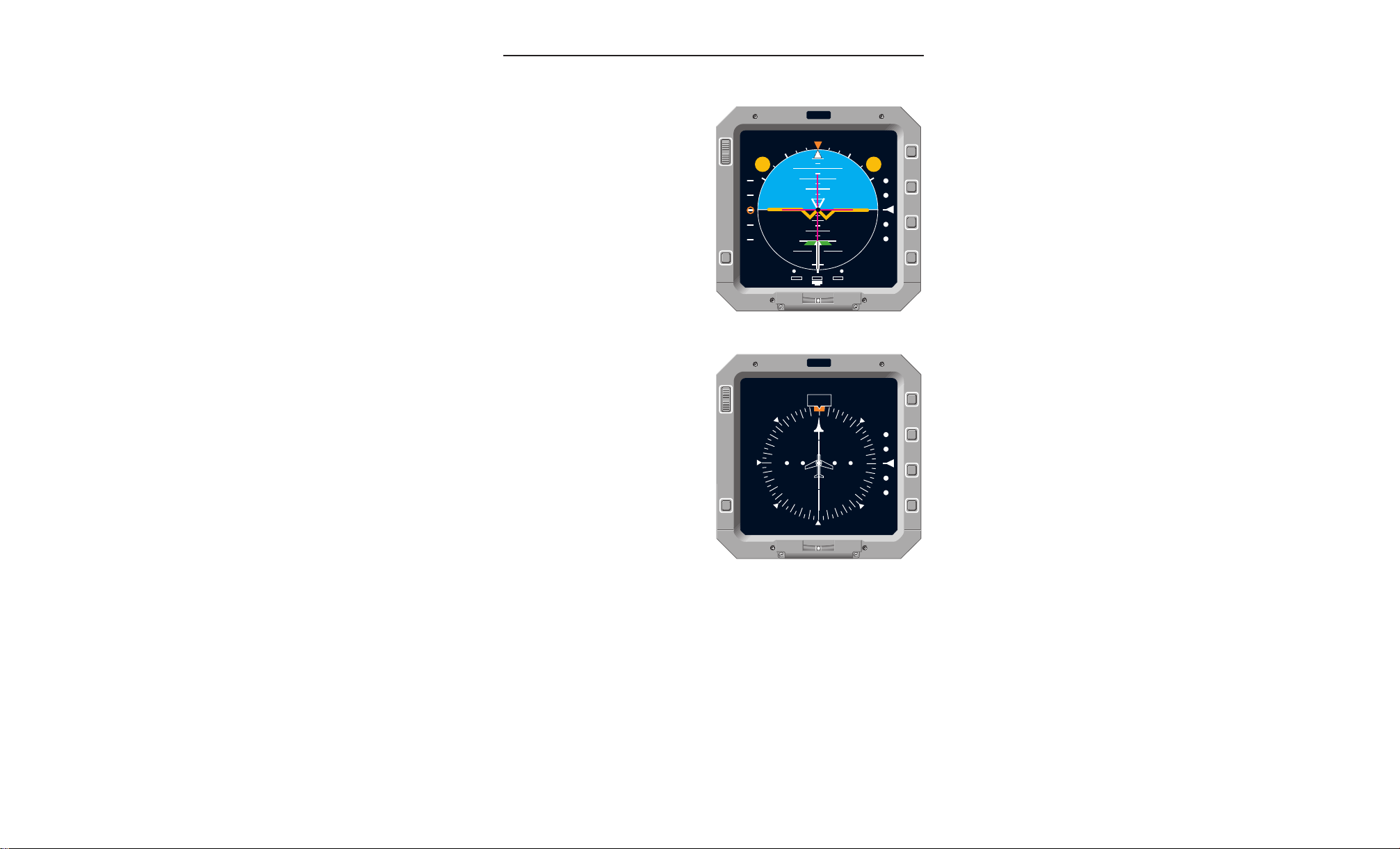
Introduction
Figure 1-1
Typical EADI Display
Figure 1-2
Typical EHSI Display
Reversionary mode capability is also provided so that during normal
operation, in the event of a failed ADI or HSI, the other FPI has the
capability to assume the function of both in the “Integrate” mode.
Reversionary mode data is hard wired into each ADI and HSI as
much as possible. Reversionary mode is discussed in more detail
later in this document.
Rev. 0
Jan/97
FPD 500 FLAT PANEL DISPLAY SYSTEM
1-1
Page 6

Introduction
A
1.1 SYSTEM DESCRIPTION
The indicator is designed for high reliability through the use of ASICs
and optimized mechanical packaging. The display is a flat panel
active matrix LCD with backlighting provided by a cold cathode fluorescent lamp.
A Graphics Processor (GP) module produces flight instrument symbology on the LCD display. The Interface Processor (IP) and I/O
modules consists of a 32 bit microprocessor, ARINC 429 interface
capability, and analog/discrete interface capability. These modules
process all of the control inputs from the indicator's front bezel/controls, external ARINC 429 input data, external discrete data (includes
superflags), synchro and analog data, and provides the interface to
the GP module. The Low Voltage Power Supply (LVPS) provides the
necessary power to all of the system’s components, while the High
Voltage Power Supply (HVPS) provides power for the cold cathode
lamp. Dimming circuitry is provided to control the lamp's brightness.
The heaters (LCD and lamp) are activated when the unit is not at the
proper operational temperature due to cold ambient conditions.
1.2 INTERNAL MONITORING
The EADI and EHSI FPDs monitor the safety and integrity of the system operation and isolate and annunciate failures as necessary.
Additional monitors provide fault isolation capability to isolate faults to
the SRU level. Loss of power to the indicator results in a completely
blank indicator. Failures that result in display of misleading information also results in a completely blank indicator. Failure conditions
due to input data failures, indicator failure, or indicator interface failures result in annunciating the appropriate failure message on the
indicator. All ADI and HSI failure warning flags are annunciated as
black text in a red box. All caution flags are annunciated as black text
in a yellow box.
Each 5ATI flat panel display contains an Interface Processor (IP) and
a Graphics Processor (GP). The IP contains built-in-test functions
that monitor the display’s “health” on a continuous basis. Detected
failures result in either annunciation to the flight crew that a display
failure exists or flagging the appropriate display data. Detected failures are also logged in non-volatile memory for retrieval later.
1-2
FPD 500 FLAT PANEL DISPLAY SYSTEM
Rev. 0
Jan/97
Page 7

A
The Graphics Processor communicates with the IP via a host interface and dual port memory. The GP executes its own BIT independent of the IP to determine its own health status. The GP also acts
as an independent monitor of the IP and the IP independently monitors the GP. If the GP detects an IP failure, it shall independently display to the flight crew a fail status message “DU FAIL”.
Integrity of displayed data is verified using two separate functions.
First, random pixels in unused portions of the LCD are driven by the
Graphics Engine and the pixel location and color are wrapped back
around and compared with the bit map of the display. Miscompares
result in displaying “DU FAIL”. Second, the IP selects a portion of the
display for monitoring by instructing the GP to return a small window
of pixels. In the case where pitch data is monitored the horizon line is
captured and the pixel data reconstituted by the IP to verify that the
correct pitch attitude was displayed. This monitoring provides an endto-end wrap around verification of displayed critical data.
Introduction
1.3 ADI/HSI FUNCTION MONITORING
Critical input data consisting of the synchro inputs of pitch, roll, and
heading are monitored for the following conditions and a failure flag is
displayed if any of these conditions exists:
1. Invalid display data or displaying misleading data.
2. Synchro input data outside “reasonable” window.
3. External data valid signal indicates "invalid".
All other input data with an associated valid signal is not used when
the data valid signal indicates “invalid”. Data in this category
includes: Course deviation, glideslope deviation, localizer deviation,
radio altitude, speed command, rate of turn, and INS/DME distance.
Rev. 0
Jan/97
FPD 500 FLAT PANEL DISPLAY SYSTEM
1-3
Page 8

Introduction
A
This page intentionally left blank.
1-4
FPD 500 FLAT PANEL DISPLAY SYSTEM
Rev. 0
Jan/97
Page 9
A
N
M
R
I
DIM
TEST
BRT
DIM
BRT
TEST
N
M
EADI/EHSI Operation
2. EADI/EHSI OPERATING CONTROLS
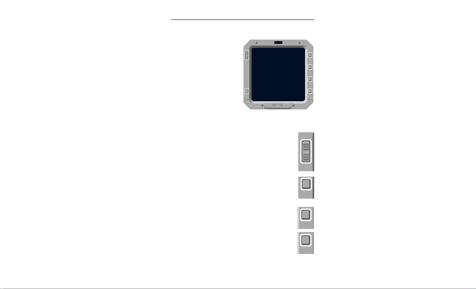
2.1 CONTROLS
The controls consist of a
BRT/DIM rocker switch, a TEST
button, four function buttons (“N”
NORM, “M” MODE, “R” RANGE,
“I” INTEGRATE), and an ambient
light sensor.
Figure 2-1
FPI Bezel
2.1.1 DISPLAY INTENSITY
Press the rocker switch on the BRT end to increase intensity
and on the DIM end to decrease intensity. The switch function is the same for both ADI and HSI.
2.1.2 TEST BUTTON
Pressing and holding the TEST button activates Self Test
and displays the test modes. The function is the same for
both ADI and HSI. Self Test is inhibited during ILS mode.
2.1.3 FUNCTION BUTTONS
2.1.3.1 “N” NORM Button
Pressing this button always reverts the display to Normal
mode (ADI or HSI).
2.1.3.2 “M” MODE Button
This button is non-functional in ADI mode. In HSI mode,
each press cycles the display between NORMAL, ARC,
WX+MAP
, and
MAP
. Italicized modes are not currently
WX,
active.
Rev. 0
Jan/97
FPD 500 FLAT PANEL DISPLAY SYSTEM
2-1
Page 10

EADI/EHSI Operation
R
I
2.1.3.3 “R” RANGE Button
A
This button is non-functional in ADI mode.
pressing this button changes ranges in MAP mode.
2.1.3.4 “I” INTEGRATE Button
Pressing this button activates the “Integrate” display mode.
Exit this mode by pressing the NORM button.
2.1.4 AMBIENT LIGHT SENSOR
Not operational.
In HSI mode,
2-2
FPD 500 FLAT PANEL DISPLAY SYSTEM
Rev. 0
Jan/97
Page 11
A
N
M
R
I
DIM
TEST
BRT
10
2020
10
55
55
1010
2020
F
S
FD DH
GS
N
M
R
I
DIM
TEST
BRT
FD
55
1010
2020
3030
40
N
M
R
I
DIM
TEST
BRT
FD
55
1010
2020
3030
40
EADI/EHSI Displays
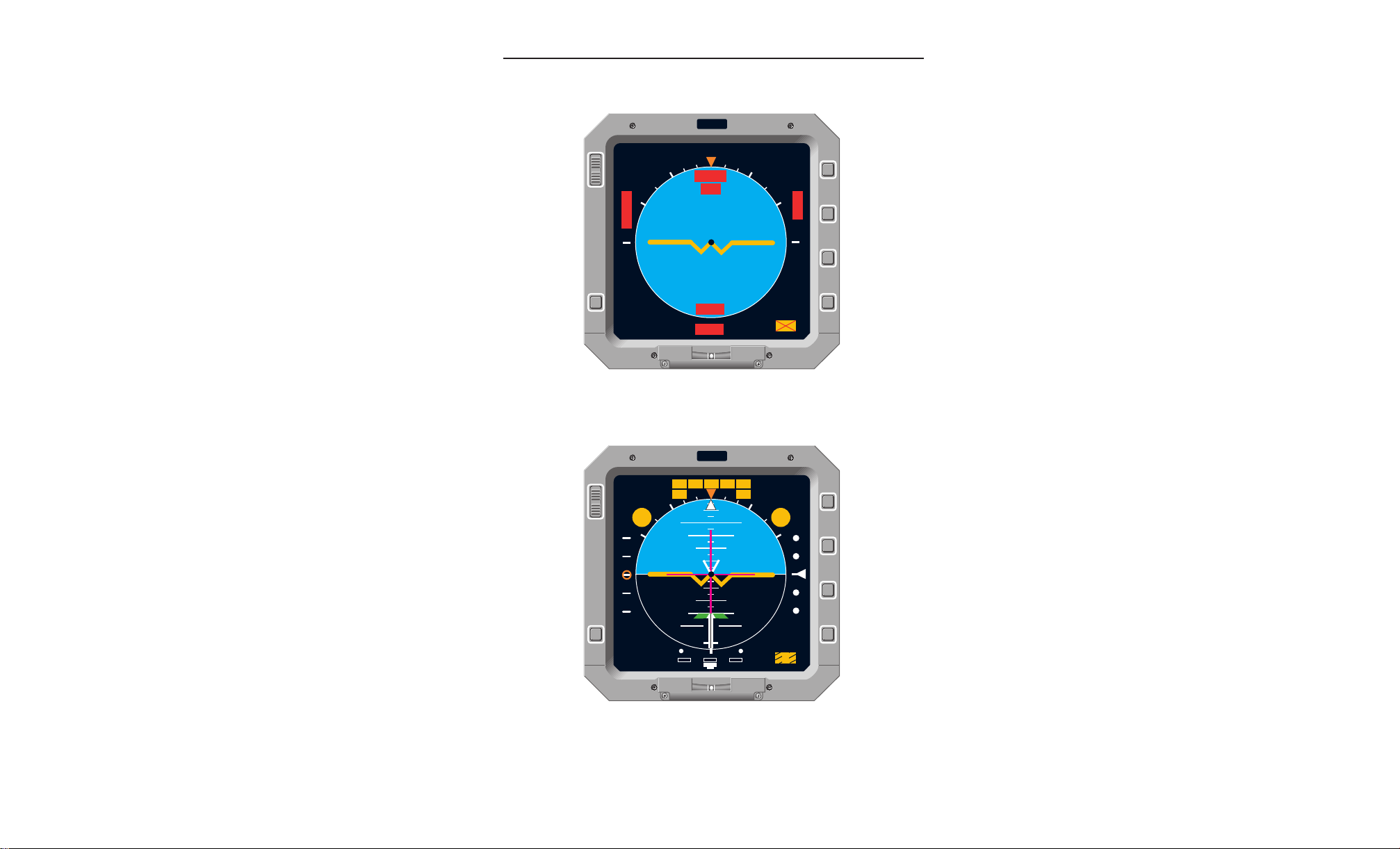
3. EADI/EHSI DISPLAYS
3.1 EADI DISPLAYS
3.1.1 PITCH ATTITUDE
A moving white simulated horizon
line rotates angularly with the roll
of the aircraft and moves up and
down with pitch of the aircraft.
Blue sky above the horizon and
black ground below the horizon
align with the horizon line as it follows the aircraft's pitch and roll.
Pitch scale reference marks
extend above and below the horizon line indicating 2.5° increments within ±30° of the horizon
line and 20° increments from 40°
to 80° from the horizon line.
Red excessive pitch chevrons are provided between 40° and 90°
pitch up (on the sky background) and between 30° and 90° pitch
down (on the ground background).
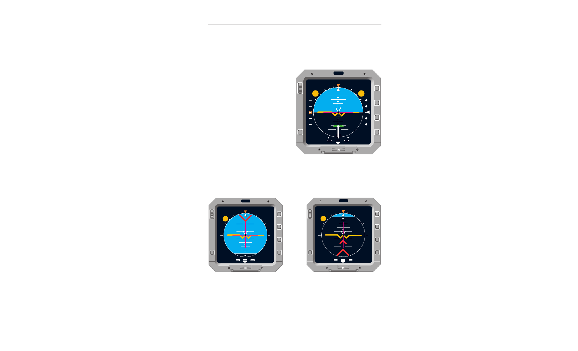
Figure 3.1-1
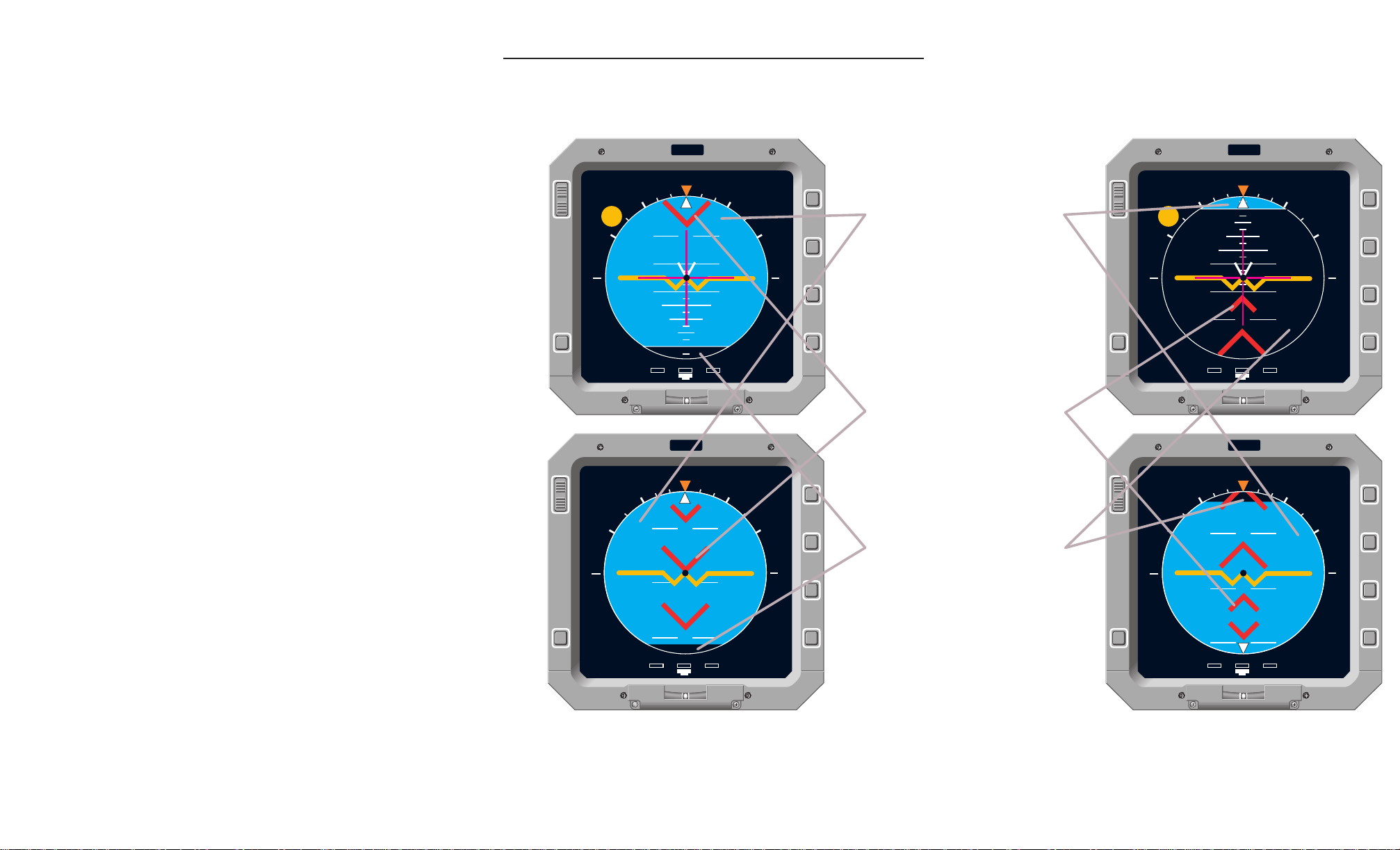
Normal Attitude Display
Figure 3.1-2
When the aircraft pitch attitude is such that the horizon line is off the
display, a small portion (eyebrow) of sky or ground will remain to indicate the direction of minimum pitch correction to return to level flight.
Rev. 0
Jan/97
FPD 500 FLAT PANEL DISPLAY SYSTEM
Excessive Pitch Up Display
Excessive Pitch Down Display
Figure 3.1-3
3-1
Page 12
EADI/EHSI Displays
10
2020
10
55
F
FD DH
GS
55
1010
55
55
1010
A
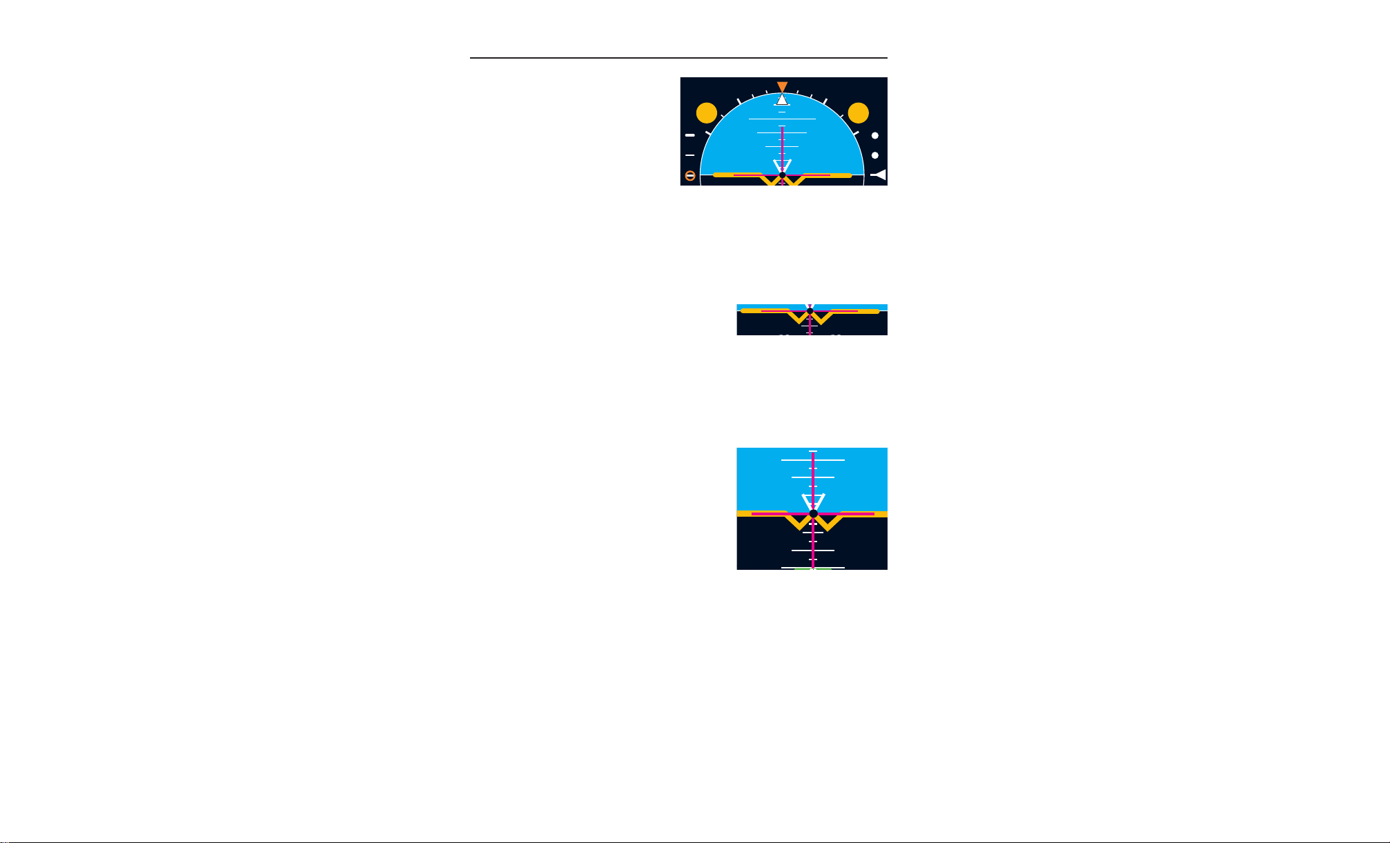
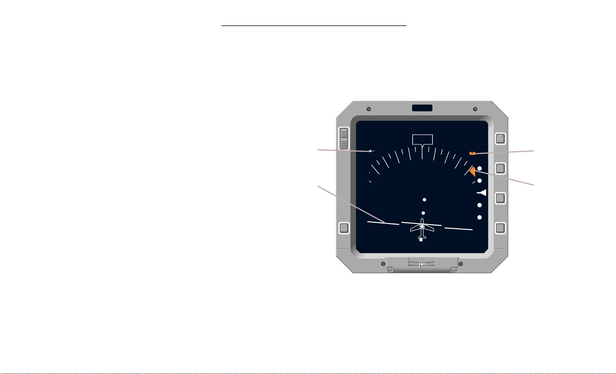
3.1.2 ROLL ATTITUDE
A white stationary roll scale with
an orange zero degree index provides the reference for the bank
angle pointer. The white sky
pointer moves in relation to the
roll scale to indicate degrees of
aircraft right or left bank. The
fixed scale is marked at 10, 20,
Figure 3.1-4
Roll Attitude
30, 45, 60, and 90 degrees, with the 30, 60 and 90 degree marks
being thicker and longer to allow easier recognition. The 90° marks
also serve as the center position on the speed command and glideslope scales.
3.1.3 SYMBOLIC AIRCRAFT
Located in the center of the display is the
fixed yellow aircraft symbol with a black dot
at the center. The pitch and roll attitudes of
Figure 3.1-5
Symbolic Aircraft
the aircraft are displayed by the relationship of the fixed symbolic aircraft and the movable horizon. The symbolic aircraft is flown to satisfy
the command cues of the flight director.
3.1.4 SPLIT CUE FLIGHT DIRECTOR
The split cue flight director is represented
by vertical and horizontal magenta bars in
the center of the EADI display about the
fixed aircraft symbol. The command bars
appear to move in front of the yellow aircraft symbol but behind the black dot. The
horizontal bar provides pitch commands
and the vertical bar provides roll commands. The bars are independently driven
and can indicate pitch only, roll only, or
Figure 3.1-6
Flight Director
combined pitch and roll commands. The flight director commands are
satisfied by flying the center black dot of the symbolic aircraft to the
intersection of the flight director command bars. The selection of the
same flight director computer by both Captain and First Officer is
annunciated by an “FD” (black text in a yellow circle). The annunciator and the command bars are removed from the display when the
flight director mode is not active.
The decrab symbol is presented as a white “V” above the symbolic
aircraft. The decrab symbol slides left or right along the wings of the
symbolic aircraft to indicate the rudder command.
3-2
FPD 500 FLAT PANEL DISPLAY SYSTEM
Rev. 0
Jan/97
Page 13
A
DIM
F
S
F
N
M
R
GS
55
1010
2020
3.1.5 RATE OF TURN
A white stationary rate of turn scale provides the reference for the rate of turn
pointer. A standard rate turn (3
degrees/second) is indicated by the pointer
aligning directly under the left or right
index.
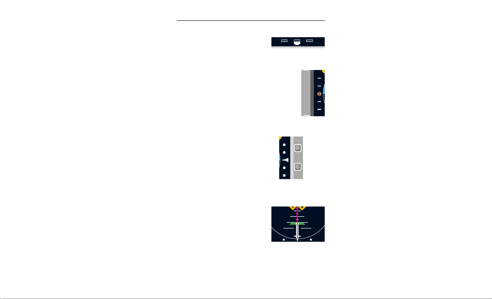
3.1.6 SPEED COMMAND
A stationary white vertical scale located on the
left side of the EADI is the reference for the
fast-slow pointer (orange circle). The speed
command circle indicates deviation from the
selected speed. Full scale deflection indicates
10 knots above or below the target airspeed.
3.1.7 GLIDESLOPE INDICATOR
A white stationary dotted vertical scale located
on the right side of the indicator is the reference for the glideslope deviation pointer (white
triangle). The glideslope pointer indicates the
center of the glideslope with respect to the
actual aircraft position.
EADI/EHSI Displays
Figure 3.1-7
Rate of Turn Indicator
Figure 3.1-8
Speed Command
Indicator
Figure 3.1-9
Glideslope Indicator
3.1.8 RISING RUNWAY
A green runway symbol representing the
airport runway moves laterally in relation to
a white expanded localizer deviation scale.
The lateral deviation indicates the aircraft
position with respect to the localizer centerline. The runway symbol rises linearly to
indicate radio altitude below 200 feet. The
runway begins to rise at 200 feet and
touches the bottom of the aircraft symbol at
zero feet of radio altitude.
Rev. 0
Jan/97
FPD 500 FLAT PANEL DISPLAY SYSTEM
Figure 3.1-10
Rising Runway
3-3
Page 14

EADI/EHSI Displays
N
20
DH
GS
DIM
20
F
FD
3.1.9 DECISION HEIGHT (DH) ANNUNCIATION
A yellow circle with “DH” in black is
displayed when the set decision height
is reached. The annunciator does not
flash.
3.1.10 FLIGHT DIRECTOR (FD)
ANNUNCIATION
A yellow circle with “FD” in black is displayed when the same Flight Director
is selected by both Captain and First
Officer. The annunciator does not
flash.
3.1.11 ADI FAILURE ANNUNCIATIONS
External sensor systems failures are annunciated in black text inside
a red box. Up to six different failures are displayed:
GYRO Attitude system failures. The bank angle pointer, pitch scale,
horizon line and black ground are removed from the display.
FD Flight Director system failures. The command bar causing
the invalid condition will be displayed as folows: Pitch
Command Bar - Full Down, Roll Comand Bar - Full Right,
Decrab Symbol - Full Left
Decision Height Annunciator
Flight Director Annunciator
A
Figure 3.1-11
Figure 3.1-12
GS Loss of Glideslope Valid during ILS Approach mode. The
glideslope scale and pointer are removed from the display.
R/T Rate of Turn invalid. The rate of turn scale and pointer are
removed from the display.
RWY Loss of LOC Valid or Radio Altitude Valid during ILS
Approach mode. The localizer scale and runway symbol are
removed from the display.
SPD Loss of Speed Command Valid. The speed comand scale
and circle are removed from the display.
Dual installations perform cross-side monitoring and display crossside failures in a yellow box in the lower right corner of the ADI display. For the failure to be displayed, 1) the cross-side sensor failure
must have been displayed on the cross-side display for at least two
seconds, or 2) the cross-side HSI has failed. A black number indicates the station where the failure occurred. A red “X” annunciation in
the yellow box indicates that the cross-side status has not been
3-4
FPD 500 FLAT PANEL DISPLAY SYSTEM
Rev. 0
Jan/97
Page 15
A
N
M
R
I
DIM
TEST
BRT
S
P
D
GYRO
FD
RWY
R/T
G
S
N
M
R
I
DIM
TEST
BRT
10
2020
10
55
55
1010
2020
F
S
FD DH
GS
2
MON
HDG PIT ROL GS LOC
ALT
EADI/EHSI Displays
Figure 3.1-13
ADI Sensor Failure Annunciation
Figure 3.1-14
ADI Cross-side Monotor Annunciation
Rev. 0
Jan/97
FPD 500 FLAT PANEL DISPLAY SYSTEM
3-5
Page 16

EADI/EHSI Displays
received for at least two seconds. All ADI failure flags flash for four to
six seconds upon initial display, then become steady indications.
3.1.12 COMPARATOR MONITOR ANNUNCIATIONS
These annunciations are only presented when configured. The
“HDG” annunciation indicates a difference exists between the
Captain and First Officer headings. Likewise, “PIT” and “ROL” indicate a difference between the pitch or roll respectively on each aircraft side. The “GS”, “LOC” and “ALT” annunciations are not operational at this time. The “MON” annunciation indicates a monitor invalid
condition exists such that comparison of cross-side information can
not be performed.
NOTE: The comparator monitor annunciations will appear during
self-test if they are configured for display. They will not appear if they
are not configured.
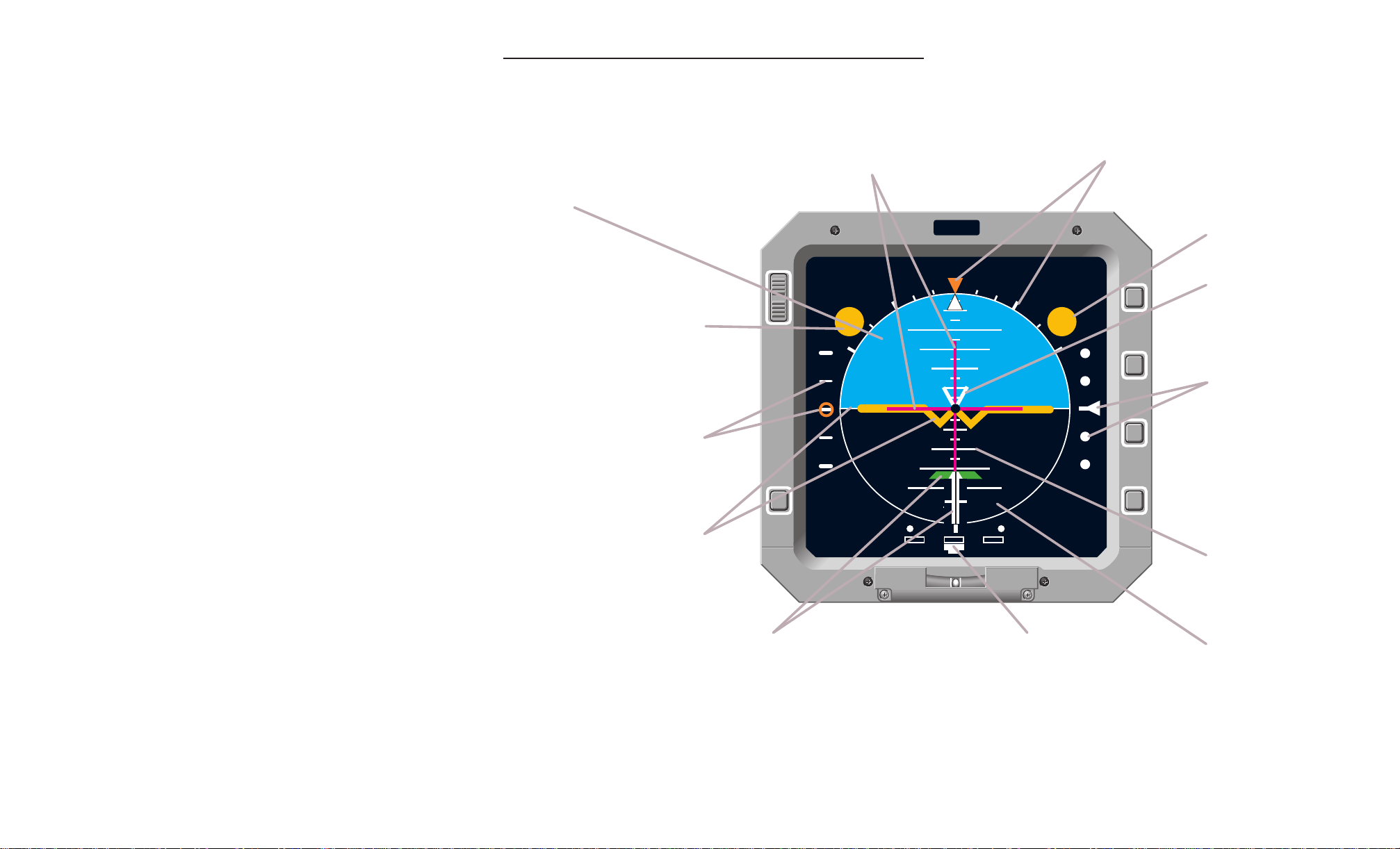
3.1.13 ADI QUICK REFERENCE
The following foldout pages provide a quick guide to the ADI displays.
A
3-6
FPD 500 FLAT PANEL DISPLAY SYSTEM
Rev. 0
Jan/97
Page 17
A
Airplane Symbol and
Horizon Bar
Airplane attitude is indicated
by the position of the fixed
aircraft symbol with respect
to the movable horizon bar.
Bank Scale and Pointer
Airplane bank angle is indicated by the
position of the white pointer on the bank
scale. Scale indices represent 0, 10, 20,
30, 45, 60 and 90 degree bank angles.
Rate of Turn Indicator
Needle indicates turn rate and
direction. Outer marks indicate
three degrees per second.
Glideslope Pointer and Scale
Pointer represents glideslope
beam and moves up or down
the glideslope deviation scale
to indicate vertical displacement
of the aircraft from the glideslope
center. In view only when
localizer is tuned and reliable
glideslope is present. The
glideslope scale and pointer are
removed when backcourse is
active.
Runway and Runway Extension Indicator
Indicates lateral displacement of the aircraft from the localizer. In
view only when a localizer is tuned. On backcourse aproaches,
the runway indicator gives reverse indications. The runway indicator
will rise vertically to indicate radio altitude from 200 feet to touchdown,
each mark on the rising runway represents 100 feet.
Command Bars
The vertical bar indicates the roll correction which the aircraft must
make to maintain a selected heading or course, and the horizontal
bar indicates the pitch correction the aircraft must make to maintain
altitude, pitch, or to track the glideslope. Bars appear when a valid
flight director mode is commanded by an external control panel.
Speed Command Circle
and Scale
Circle moves up or down
the scale to indicate
deviation from selected
airspeed.
N
M
R
I
DIM
TEST
BRT
10
2020
10
55
55
1010
2020
F
S
FD DH
GS
Sky
Ground
Decision Height (DH)
Annunciation
Indicates when decision
height is reached.
Flight Director (FD)
Annunciation
Indicates when same flight
director computer is driving
command bars on both
Captain and FO sides.
Pitch Scale
Indicates amount of pitch
up/down. Graduated in 2.5°
increments within ±30° of the
horizon line and in 20°
increments from 40 ° to 80°.
Decrab Symbol
Indicates rudder command
required to align aircraft with the
runway . The decrab symbol is
only displayed on an autopilot
coupled approach.
EADI/EHSI Displays
Rev. 0
Jan/97
Figure 3.1-15
Normal ADI Quick Reference
FPD 500 FLAT PANEL DISPLAY SYSTEM
3-7
Page 18

EADI/EHSI Displays
A
This page intentionally left blank.
3-8
FPD 500 FLAT PANEL DISPLAY SYSTEM
Rev. 0
Jan/97
Page 19
A
N
M
R
I
DIM
TEST
BRT
40
80
60
N
M
R
I
DIM
TEST
BRT
60
80
80
N
M
R
I
DIM
TEST
BRT
FD
55
1010
2020
3030
40
N
M
R
I
DIM
TEST
BRT
FD
55
1010
2020
3030
40
Sky
An eyebrow of sky will
always be shown, even if
the pitch exceeds viewable
limits of the sky. If the pitch
changes from what is shown
to drive the remaining sky
off the display, the eyebrow
will remain and the horizon
line will drive off the display .
Ground
An eyebrow of ground will
always be shown, even if
the pitch exceeds viewable
limits of the ground. If the
pitch changes from what is
shown to drive the remaining
ground off the display, the
eyebrow will remain and the
horizon line will drive off the
display .
Chevrons
Red Chevrons indicate
direction of pitch correction
to return to a normal pitch
attitude. They first appear
23° Nose Up and 10° Nose
Down
EADI/EHSI Displays
Figure 3.1-16
Excessive Pitch ADI Quick Reference
Rev. 0
Jan/97
FPD 500 FLAT PANEL DISPLAY SYSTEM
3-9
Page 20

EADI/EHSI Displays
A
This page intentionally left blank.
3-10
FPD 500 FLAT PANEL DISPLAY SYSTEM
Rev. 0
Jan/97
Page 21

A
N
M
R
I
DIM
TEST
BRT
0
33
30
27
24
21
15
12
9
6
3
18
000
GS
TRU
ILS 1
INS1
1234
INS2
1324
TEST
ILS 1
EADI/EHSI Displays
3.2 EHSI DISPLAYS
The EHSI is capable of displaying five different presentations of the
horizontal situation. The Mode (M) button cycles the display through
Normal, ARC, Wx, Wx + MAP, and MAP modes. The Wx modes are
not currently implemented.
3.2.1 NORMAL HSI DISPLAY
3.2.1.1 Azimuth Card
A 360 degree rotating white
azimuth card indicates aircraft
heading referenced to a white
rectangular box with a triangular
heading index mark (lubber line)
protruding from the bottom. The
heading index box is shown at
the top center of the azimuth
card, and contains digital heading
in integer degrees (0 thru 359).
The heading is shown with
respect to True or Magnetic
north, and a blue “TRU” above
the heading index box indicates
the current reference. A fixed
white symbolic aircraft in the center of the azimuth card indicates
the aircraft’s relationship to the horizontal situation display. The
azimuth card is divided into five degree increments, with the 10
degree divisions being longer to help with identification of the current
heading. Fixed 45 degree markers (white triangles) are positioned
around the outside of the azimuth card.
Figure 3.2-1
Normal HSI Display
3.2.1.2 Navigation Source Annunciation
The navigation system selected by the
flight crew is annunciated in white in the
lower left corner of the display. Three navigation sources are possible: ILS, VOR, or
NAV. Up to three of each system can be
annunciated (e.g. NAV1, NAV2, NAV3).
Rev. 0
Jan/97
FPD 500 FLAT PANEL DISPLAY SYSTEM
Figure 3.2-2
Navigation Source
Annunciation
3-11
Page 22

EADI/EHSI Displays
000
0
33
30
27
24
21
15
12
9
6
3
18
30
27
24
12
9
6
3.2.1.3 Selected Heading
An orange notched heading bug is manually rotated around the azimuth card by an
external heading select knob. The heading
bug indicates selected heading, and once
set, rotates with the azimuth card.
3.2.1.4 Selected Course
A white selected course pointer is manually rotated around the azimuth card by an
external course select knob. The pointer
indicates the desired navigation course,
and once set, rotates with the azimuth
card. When the primary navigation source
is an INS (NAV annunciated) desired track
from the INS is used to position the course
pointer.
3.2.1.5 Course Deviation Display
The course deviation scale (five white
dots) provides a reference for the course
deviation bar. The course deviation bar is
the center bar of the selected course
pointer. The course deviation bar indicates
the centerline of the selected navigation
course or localizer course in relation to the
symbolic aircraft. The course deviation
scale and pointer rotate with the azimuth
card when set.
A
Figure 3.2-3
Selected Heading Bug
Figure 3.2-4
Selected Course Pointer
Figure 3.2-5
Course Deviation Display
3.2.1.6 Bearing Pointer(s)
Not currently implemented.
Rev. 0
Jan/97
3-12
FPD 500 FLAT PANEL DISPLAY SYSTEM
Page 23

A
TRU
INS1
1234
INS2
1324
TRU
INS1
----
INS2
----
0
33
30
6
3
G
2
24
21
15
12
18
M
R
GS
EADI/EHSI Displays
3.2.1.7 Distance Display
Two white alphanumeric distance displays provide the distance in
nautical miles from the aircraft to the selected DME or VORTAC station in the standard navigation mode
(DME), or distance to a waypoint in the
INS mode. The distance source is annunciated above its respective distance
value. If distance data is invalid, the dis-
Figure 3.2-6
Distance Display
tance value is replaced by dashes. When
distance data is missing, the entire disance display is removed. DME distance
is shown as XXX.X from 0.0 thru 399.9
NM. INS/LNAV distance is shown as
XXX.X from 0.0 thru 999.9 and as XXXX
Figure 3.2-7
Invalid Distance Display
for 1000 NM and above.
3.2.1.8 To/From Display
An orange arrowhead near the center of
the azimuth card pointing towards the
head of the course pointer represents the
“TO” indication, pointing towards the tail
Figure 3.2-8
“TO” Display
of the course pointer represents the
“FROM” indication. The arrowhead points
toward the navigation station or waypoint,
indicating whether the current selected
course is TO or FROM the navigation
station or waypoint.
Figure 3.2-9
“FROM” Display
3.2.1.9 Glideslope Display
A white stationary dotted vertical scale located
on the right side of the indicator is the reference for the glideslope deviation pointer (white
triangle). The glideslope pointer indicates the
center of the glideslope with respect to the
actual aircraft position.
3.2.1.10 Drift Angle Display
Figure 3.2-10
Glideslope Indicator
Not currently implemented.
3.2.1.11 Ground Speed Display
Not currently implemented.
Rev. 0
Jan/97
FPD 500 FLAT PANEL DISPLAY SYSTEM
3-13
Page 24

EADI/EHSI Displays
N
M
R
I
DIM
TEST
BRT
0
33
6
3
000
GS
TRU
ILS 1
INS1
1234
INS2
1324
ARC
0
33
3
GS
0
33
3
3.2.2 ARC HSI DISPLAY
The ARC format provides for display of weather radar data (not
currently supported) and provides
increased resolution of the displayed navigation data due to the
enlarged scale.
3.2.2.1 Azimuth Card
The azimuth card functions the
same as in normal HSI mode,
except only 45 degrees on either
side of the current heading is visible.
3.2.2.2 Navigation Source Annunciation
Same as Normal mode.
3.2.2.3 Selected Heading
Same as Normal mode, except that when
the heading bug moves off the visible
scale, a small orange heading bug symbol
is displayed above the right or left edge of
the azimuth scale to indicate its actual location.
A
Figure 3.2-11
ARC HSI Display
Figure 3.2-12
Selected Heading Bug
3.2.2.4 Selected Course
Same as Normal mode, except the lower
portion of the pointer is out of view and
when the pointer moves off the visible
scale, a small white selected course arrow
symbol is displayed above the right or left
edge of the azimuth scale to indicate its
actual location.
3.2.2.5 Course Deviation Display
Same as Normal mode.
Figure 3.2-13
Selected Course Pointer
3.2.2.6 Bearing Pointer(s)
Not currently implemented.
3-14
FPD 500 FLAT PANEL DISPLAY SYSTEM
Rev. 0
Jan/97
Page 25

A
N
M
R
I
DIM
TEST
BRT
0
33
6
3
000
GS
TRU
ILS 1
INS1
1234
INS2
1324
MAP
- - -
- -
EADI/EHSI Displays
3.2.2.7 Distance Display
Same as Normal mode.
3.2.2.8 To/From Display
Same as Normal mode.
3.2.2.9 Glideslope Display
Same as Normal mode.
3.2.2.10 Drift Angle Display
Not currently implemented.
3.2.2.11 Ground Speed Display
Not currently implemented.
3.2.3 MAP HSI DISPLAY
The MAP format provides for increased resolution of the displayed
navigation data due to the enlarged scale. It also provides range
information. The MAP mode display is the same as ARC except as
noted in the following paragraphs.
3.2.3.1 Range Rings
The azimuth card forms the outer
range ring. The inner range ring
represents half the distance to the
outer range ring. The half-range
distance is annunciated at the
bottom right end of the inner ring.
The full map range is annunciated in the lower left corner of the
display, directly under the mode
annunciation. Currently, the range
3.2.3.2 MAP Waypoints
Not currently implemented.
Rev. 0
Jan/97
FPD 500 FLAT PANEL DISPLAY SYSTEM
is annunciated as dashes only.
Figure 3.2-14
MAP Display
3-15
Page 26

EADI/EHSI Displays
N
M
R
I
DIM
TEST
BRT
0
33
30
27
24
21
15
12
9
6
3
18
NAV 1
HDG
G
S
NAV
A
L
E
R
T
A
3.2.4 WX DISPLAY
Not currently implemented.
3.2.5 WX + MAP DISPLAY
Not currently implemented.
3.2.6 HSI FAILURE ANNUNCIATIONS
External sensor systems failures are annunciated in black text inside
a red box. Up to three different failures are displayed:
HDG Loss of Compass or Heading Valid. The digital heading is
removed from the display, but the compass card remains
on the display. See Special Considerations section.
NAV Loss of Course Deviation Valid. The deviation bar and
or VOR scale are removed from the display. The to/from arrow is
or ILS also removed from the display if the navigation source is
NAV or VOR.
GS Loss of Glideslope Valid during ILS Approach mode. The
glideslope scale and pointer are removed from the display.
An additional annunciation of
“ALERT” is provided when an
INS waypoint is approached.
A red “X” annunciation in the
yellow cross-side failure box
indicates that the cross-side
status has not been received
for at least two seconds. All
HSI failure flags flash for four
to six seconds upon initial display, then become steady
indications.
NOTE: The only cross-side
failure annunciated by a normal HSI (Integrate mode not
active) is the red “X” indicating the loss of cross-side
HSI Sensor Failure Annunciation
information. With Integrate mode active, an HSI will display the same
cross-side failure information provided by an ADI.
3.2.7 HSI QUICK REFERENCE
The following foldout pages provide a quick guide to the HSI displays.
3-16
FPD 500 FLAT PANEL DISPLAY SYSTEM
Figure 3.2-15
Rev. 0
Jan/97
Page 27

A
N
M
R
I
DIM
TEST
BRT
0
33
30
27
24
21
15
12
9
6
3
18
000
GS
TRU
ILS 1
INS1
1234
INS2
1324
Airplane Symbol
Indicates aircraft relationship
to the horizontal display.
Compass Card
Indicates aircraft magnetic
or true heading under
lubber mark.
Course Deviation Indicator and Scale
Indicates the centerline of the selected
navigation course in relation to the
aircraft symbol.
Glideslope Pointer and
Scale
Pointer represents glideslope
beam and moves up or down
the glideslope deviation scale
to indicate vertical
displacement of the aircraft
from the glideslope center. In
view only when localizer is
tuned and reliable glideslope
is present.
Navigation Source
Indicates the navigation
source selected to drive the
HSI course deviation.
Possible annunciations are
"NAV", "VOR" or "ILS".
Digital Heading Readout
and Lubber Mark
Indicates digital value of magnetic or
true heading from the selected navigation
system. Lubber mark indicates heading
of aircraft on compass card.
Distance Readout
Indicates distance in nautical
miles from the selected DME
or waypoint according to
navigation system 1.
Distance Readout
Indicates distance in nautical
miles from the selected DME
or waypoint according to
navigation system 2.
Heading Bug
Indicates selected heading
on the compass card. The
bug is set via an external
heading select knob. Once
set, the bug rotates with the
compass card to provide
continuous indication of the
selected heading.
Mag/True Annunciator
Indicates which aircraft heading
data is shown: magnetic (blank)
or true (TRU).
To/From Pointer
Indicates if selected course
is to or from the selected
VOR Station. Not displayed
with ILS active.
Selected Course Arrow
Indicates selected course on
the compass card. The arrow
is set via an external course
select knob. Once set, the
arrow rotates with the
compass card to provide
continuous indication of the
selected course.
EADI/EHSI Displays
Rev. 0
Jan/97
Normal HSI Quick Reference
FPD 500 FLAT PANEL DISPLAY SYSTEM
Figure 3.2-16
3-17
Page 28

EADI/EHSI Displays
A
This page intentionally left blank.
3-18
FPD 500 FLAT PANEL DISPLAY SYSTEM
Rev. 0
Jan/97
Page 29

A
N
M
R
I
DIM
TEST
BRT
0
33
6
3
000
GS
TRU
ILS 1
INS1
1234
INS2
1324
ARC
Airplane Symbol
Indicates aircraft relationship
to the horizontal display.
Compass Card
Indicates aircraft magnetic
or true heading under
lubber mark.
Course Deviation Indicator and Scale
Indicates the centerline of the selected
navigation course in relation to the
aircraft symbol.
Glideslope Pointer and
Scale
Pointer represents glideslope
beam and moves up or down
the glideslope deviation scale
to indicate vertical
displacement of the aircraft
from the glideslope center. In
view only when localizer is
tuned and reliable glideslope
is present.
Navigation Source
Indicates the navigation
source selected to drive the
HSI course deviation.
Digital Heading Readout
and Lubber Mark
Indicates digital value of magnetic or
true heading from the selected navigation
system. Lubber mark indicates heading
of aircraft on compass card.
Distance Readout
Indicates distance in nautical
miles from the selected DME
or waypoint according to
navigation system 1.
Distance Readout
Indicates distance in nautical
miles from the selected DME
or waypoint according to
navigation system 2.
Heading Bug
Indicates selected heading
on the compass card. The
bug is set via an external
heading select knob. Once
set, the bug rotates with the
compass card to provide
continuous indication of the
selected heading.
Mag/True Annunciator
Indicates which aircraft heading
data is shown: magnetic (blank)
or true (TRU).
To/From Pointer
Indicates if selected course
is to or from the selected
VOR Station or waypoint. Not
displayed with ILS active.
Selected Course Arrow
Indicates selected course on
the compass card. The arrow
is set via an external course
select knob. Once set, the
arrow rotates with the
compass card to provide
continuous indication of the
selected course.
HSI Display Mode
Indicates ARC or MAP
display.
EADI/EHSI Displays
Rev. 0
Jan/97
Figure 3.2-17
ARC HSI Quick Reference
FPD 500 FLAT PANEL DISPLAY SYSTEM
3-19
Page 30

EADI/EHSI Displays
A
This page intentionally left blank.
3-20
FPD 500 FLAT PANEL DISPLAY SYSTEM
Rev. 0
Jan/97
Page 31
A
N
M
R
I
DIM
TEST
BRT
0
33
6
3
000
GS
TRU
ILS 1
INS1
1234
INS2
1324
ARC
Heading Bug Locator
Indicates to which side the
heading bug is closest.
Heading Bug
Indicates selected heading
on the compass card. The
bug is set via an external
heading select knob. Once
set, the bug rotates with the
compass card to provide
continuous indication of the
selected heading.
Selected Course Arrow
Indicates selected course on
the compass card. The arrow
is set via an external course
select knob. Once set, the
arrow rotates with the
compass card to provide
continuous indication of the
selected course.
Course Pointer Locator
Indicates to which side the
course pointer is closest.
EADI/EHSI Displays
Figure 3.2-18
Off-Scale ARC HSI Quick Reference
Rev. 0
Jan/97
FPD 500 FLAT PANEL DISPLAY SYSTEM
3-21
Page 32

EADI/EHSI Displays
A
This page intentionally left blank.
3-22
FPD 500 FLAT PANEL DISPLAY SYSTEM
Rev. 0
Jan/97
Page 33

A
N
M
R
I
DIM
TEST
BRT
0
33
6
3
000
GS
TRU
ILS 1
INS1
1234
INS2
1324
MAP
- - -
- -
Airplane Symbol
Indicates aircraft relationship
to the horizontal display.
Compass Card
Indicates aircraft magnetic
or true heading under
lubber mark.
Course Deviation Indicator and Scale
Indicates the centerline of the selected
navigation course in relation to the
aircraft symbol.
Glideslope Pointer and
Scale
Pointer represents glideslope
beam and moves up or down
the glideslope deviation scale
to indicate vertical
displacement of the aircraft
from the glideslope center. In
view only when localizer is
tuned and reliable glideslope
is present.
Navigation Source
Indicates the navigation
source selected to drive the
HSI course deviation.
Digital Heading Readout
and Lubber Mark
Indicates digital value of magnetic or
true heading from the selected navigation
system. Lubber mark indicates heading
of aircraft on compass card.
Distance Readout
Indicates distance in nautical
miles from the selected DME
or waypoint according to
navigation system 1.
Distance Readout
Indicates distance in nautical
miles from the selected DME
or waypoint according to
navigation system 2.
Heading Bug
Indicates selected heading
on the compass card. The
bug is set via an external
heading select knob. Once
set, the bug rotates with the
compass card to provide
continuous indication of the
selected heading.
Mag/True Annunciator
Indicates which aircraft heading
data is shown: magnetic (blank)
or true (TRU).
To/From Pointer
Indicates if selected course
is to or from the selected VOR
Station or waypoint. Not
displayed with ILS active.
Selected Course Arrow
Indicates selected course on
the compass card. The arrow
is set via an external course
select knob. Once set, the
arrow rotates with the
compass card to provide
continuous indication of the
selected course.
HSI Display Mode
Indicates ARC or MAP
display.
Half-Range Ring and
Annunciator
Indicates half of the full map
range selected. Currently
indicates dashes only.
Full-Range Annunciator
Indicates the full map range
selected. The azimuth scale
represents the full range
ring. Currently indicates
dashes only.
EADI/EHSI Displays
Rev. 0
Jan/97
MAP HSI Quick Reference
FPD 500 FLAT PANEL DISPLAY SYSTEM
Figure 3.2-19
3-23
Page 34

EADI/EHSI Displays
N
M
R
I
DIM
TEST
BRT
10
2020
10
55
55
1010
2020
F
S
FD DH
GS
0
33
30
27
9
6
3
TRU
NAV 1
N
M
R
I
DIM
TEST
BRT
0
33
30
27
9
6
3
S
P
D
GYRO
FD
HDG
NAV
G
S
2
A
L
E
R
T
MON
HDG PIT ROL GS LOC
ALT
A
3.3 INTEGRATE MODE
The EADI and the EHSI both can
provide the Integrated display as
a reversionary mode, and the
integrated display is identical on
either an ADI or HSI. The ADI
and HSI display functions are the
same as they would be on an ADI
or HSI alone, except that the rate
of turn display and the rising runway are not displayed, and the
to/from pointer is duplicated on
both sides of the symbolic aircraft. Off scale symbols (heading
bug and course pointer) are displayed as in the ARC HSI mode.
On a display configured as an
ADI, a pitch value of more than 23 degrees up or down will result in
the display reverting to the ADI presentation. The display will not
automatically return to Integrate mode when pitch value is reduced to
less than 23 degrees. The Integrate mode must be manually reselected. On a display configured as an HSI, pitch value does not
cause the display to revert to HSI mode.
Figure 3.3-1
Integrate Display
3.3.1 INTEGRATE MODE FAILURE ANNUNCIATIONS
External failures are annumciated in the same way as on
the ADI and HSI, except
“RWY” and “R/T”, because
the rising runway and the rate
of turn indicator are not
shown on the integrate display.
3.3.2 INTEGRATE MODE
QUICK REFERENCE
The following foldout pages
provide a quick guide to the
Integrate Mode displays.
3-24
FPD 500 FLAT PANEL DISPLAY SYSTEM
Figure 3.3-2
Integrate Mode Failure Annunciation
Rev. 0
Jan/97
Page 35

A
N
M
R
I
DIM
TEST
BRT
10
2020
10
55
55
1010
2020
F
S
FD DH
GS
0
33
30
27
9
6
3
TRU
NAV 1
Airplane Symbol and
Horizon Bar
Airplane attitude is indicated
by the position of the fixed
aircraft symbol with respect
to the movable horizon bar.
Bank Scale and Pointer
Airplane bank angle is indicated by the
position of the white pointer on the bank
scale. Scale indices represent 0, 10, 20,
30, 45, 60 and 90 degree bank angles.
Glideslope Pointer and Scale
Pointer represents glideslope
beam and moves up or down
the glideslope deviation scale
to indicate vertical
displacement of the aircraft
from the glideslope center. In
view only when localizer is
tuned and reliable glideslope
is present. The glideslope scale
and pointer are removed when
backcourse is active.
Command Bars
The vertical bar indicates the roll correction which the aircraft must
make to maintain a selected heading or course, and the horizontal
bar indicates the pitch correction the aircraft must make to maintain
altitude, pitch, or to track the glideslope. Bars appear when a valid
flight director mode is commanded by an external control panel.
Speed Command Circle
and Scale
Circle moves up or down
the scale to indicate
deviation from selected
airspeed.
Sky
A small amount of sky will
always be shown if at the
top of the ADI, even if the
pitch exceeds viewable
limits of the sky.
Ground
A small amount of ground will always be shown, if at the top of
the ADI, even if the pitch exceeds viewable limits of the ground.
The eyebrow of ground will be obscured by the compass card at
the bottom.
Decision Height (DH)
Annunciation
Indicates when decision
height is reached.
Flight Director (FD)
Annunciation
Indicates when same flight
director computer is driving
command bars on both
Captain and FO sides.
Pitch Scale
Indicates amount of pitch
up/down. Graduated in 2.5°
increments within ±30° of the
horizon line and in 20°
increments from 40 ° to 80°.
Decrab Symbol
Indicates rudder command
required to align aircraft with
runway . The decrab symbol
is only displayed on an
autopilot coupled approach.
INS1
1234
INS2
1324
EADI/EHSI Displays
Integrate Mode ADI Quick Reference
Figure 3.3-3
Rev. 0
Jan/97
FPD 500 FLAT PANEL DISPLAY SYSTEM
3-25
Page 36

EADI/EHSI Displays
A
This page intentionally left blank.
3-26
FPD 500 FLAT PANEL DISPLAY SYSTEM
Rev. 0
Jan/97
Page 37

N
M
R
I
DIM
TEST
BRT
10
2020
10
55
55
1010
2020
F
S
FD DH
GS
0
33
30
27
9
6
3
TRU
NAV 1
Airplane Symbol
Indicates aircraft relationship
to the horizontal display.
Compass Card
Indicates aircraft magnetic
or true heading under
lubber mark.
Course Deviation Indicator and Scale
Indicates the centerline of the selected
navigation course in relation to the
aircraft symbol.
Navigation Source
Indicates the navigation
source selected to drive the
HSI course deviation which
is also displayed on the ADI
in Integrate Mode.
Lubber Mark
Indicates heading of aircraft
on compass card.
Heading Bug
Indicates selected heading
on the compass card. The
bug is set via an external
heading select knob. Once
set, the bug rotates with the
compass card to provide
continuous indication of the
selected heading. When
driven out of view, a small
heading bug is displayed
over the right or left end of
the azimuth card to show
the location.
Mag/True Annunciator
Indicates which aircraft heading
data is shown: magnetic (blank)
or true (TRU).
To/From Pointer
Indicates if selected course is to
or from the selected VOR Station
or waypoint. Duplicated on both
ends of the course pointer so
that at least one will always be
visible.
Selected Course Arrow
Indicates selected course on the
compass card. The arrow is set
via an external course select
knob. Once set, the arrow rotates
with the compass card to provide
continuous indication of the
selected course. When driven out
of view, a small arrow displayed
over the right or left end of the
azimuth card to show the location.
Distance Readout
Indicates distance in nautical
miles from the selected DME
or waypoint according to
navigation system 1.
Distance Readout
Indicates distance in nautical
miles from the selected DME
or waypoint according to
navigation system 2.
INS1
1234
INS2
1324
A
L
E
R
T
Alert Annunciator
Indicates that an INS
waypoint is being
approached.
A
EADI/EHSI Displays
Integrate Mode HSI Quick Reference
Rev. 0
Jan/97
FPD 500 FLAT PANEL DISPLAY SYSTEM
Figure 3.3-4
3-27
Page 38

EADI/EHSI Displays
A
This page intentionally left blank.
3-28
FPD 500 FLAT PANEL DISPLAY SYSTEM
Rev. 0
Jan/97
Page 39

A
Special Considerations
4. SPECIAL CONSIDERATIONS
4.1 NAVIGATION SOURCE COMBINATIONS
During approach mode (a valid ILS frequency selected), a normal
EADI will display a glideslope scale with pointer and a rising runway.
When displayed, the glideslope pointer position is always determined
by the on-side glideslope receiver. The lateral position of the runway
is always determined by the on-side localizer and the vertical position of the runway is always determined by the on-side radio altimeter. Cross-side and other sensors are never used, therefore there is
no need to identify these sensor sources. During enroute mode (a
valid ILS frequency is not selected) the glideslope scale and runway
symbol are removed from the EADI display.
The navigation sources used to position the course deviation bar on
the EHSI are identified since three sources are possible. INS is
annunciated as “NAV”, VOR is annunciated as “VOR” and localizer is
annunciated as “ILS”. The glideslope scale with pointer position
determined by the glideslope receiver is also displayed when the
course deviation bar is driven by the localizer receiver and “ILS” is
annunciated as the navigation source. The glideslope scale and
pointer are removed from display on the EHSI when the selected
sensor is “VOR” or “NAV”.
When Integrate mode is selected on an EADI, the navigation source
used to position the course deviation bar on the integrated display will
match that selected for use on the associated EHSI. These navigation sources are identified with the same annunciations used on the
EHSI.
Some aircraft installations allow independent selection of navigation
sensors for the EADI and EHSI. This can result in unexpected combinations of sensors between the two displays and also on a single
EADI display with the Integrate mode selected. For example, the
presence of a glideslope scale and pointer on an EADI in Integrate
mode does not insure that the course deviation bar on the same display is driven by the localizer. The actual navigation source of lateral
deviation may be NAV, VOR or ILS as selected for the EHSI. The
correct navigation source is annunciated in all cases and must be
used to avoid confusion. All the possible combinations are shown in
the following figures.
Rev. 0
Jan/97
FPD 500 FLAT PANEL DISPLAY SYSTEM
4-1
Page 40

N
M
R
I
DIM
TEST
BRT
N
M
R
I
DIM
TEST
BRT
N
M
R
I
DIM
TEST
BRT
N
M
R
I
DIM
TEST
BRT
10
2020
10
55
55
1010
2020
F
S
GS
0
33
30
27
9
6
3
TRU
NAV 1
INS1
1234
INS2
1324
10
2020
10
55
55
1010
2020
F
S
0
33
30
27
9
6
3
TRU
NAV 1
INS1
1234
INS2
1324
ADI ENROUTE ADI APPROACH
0
33
30
27
24
21
15
12
9
6
3
18
000
TRU
NAV 1
INS1
1234
INS2
1324
0
33
30
27
24
21
15
12
9
6
3
18
000
TRU
NAV 1
INS1
1234
INS2
1324
Special Considerations
A
Figure 4.1-1
HSI on NAV (INS)
4-2
FPD 500 FLAT PANEL DISPLAY SYSTEM
Rev. 0
Jan/97
Page 41

N
M
R
I
DIM
TEST
BRT
N
M
R
I
DIM
TEST
BRT
N
M
R
I
DIM
TEST
BRT
N
M
R
I
DIM
TEST
BRT
10
2020
10
55
55
1010
2020
F
S
GS
0
33
30
27
9
6
3
VOR 1
INS1
1234
INS2
1324
10
2020
10
55
55
1010
2020
F
S
0
33
30
27
9
6
3
VOR 1
INS1
1234
INS2
1324
ADI ENROUTE ADI APPROACH
0
33
30
27
24
21
15
12
9
6
3
18
000
VOR 1
INS1
1234
INS2
1324
0
33
30
27
24
21
15
12
9
6
3
18
000
VOR 1
INS1
1234
INS2
1324
A
Special Considerations
Figure 4.1-2
HSI on VOR
Rev. 0
Jan/97
FPD 500 FLAT PANEL DISPLAY SYSTEM
4-3
Page 42
N
M
R
I
DIM
TEST
BRT
N
M
R
I
DIM
TEST
BRT
N
M
R
I
DIM
TEST
BRT
N
M
R
I
DIM
TEST
BRT
10
2020
10
55
55
1010
2020
F
S
GS
0
33
30
27
9
6
3
ILS 1
INS1
1234
INS2
1324
10
2020
10
55
55
1010
2020
F
S
0
33
30
27
9
6
3
ILS 1
INS1
1234
INS2
1324
ADI ENROUTE ADI APPROACH
0
33
30
27
24
21
15
12
9
6
3
18
000
ILS 1
INS1
1234
INS2
1324
0
33
30
27
24
21
15
12
9
6
3
18
000
ILS 1
INS1
1234
INS2
1324
ILS
ILS
GS
G
S
Special Considerations
A
Figure 4.1-3
HSI on ILS
4-4
FPD 500 FLAT PANEL DISPLAY SYSTEM
Rev. 0
Jan/97
Page 43

A
N
M
R
I
DIM
TEST
BRT
0
33
30
27
24
21
15
12
9
6
3
18
GS
ILS 1
INS1
1234
INS2
1324
HDG
Special Considerations
4.2 HEADING FAILURE
Invalid heading is indicated by replacing the digital heading readout
with a red “HDG” flag. The compass card will continue to be displayed and will rotate in response to the heading signal received by
the EHSI. If the heading signal is not received by the EHSI, the compass card will freeze at the last valid value for heading and the “HDG”
flag will be in view.
When the “HDG” flag is displayed, the positions of the selected heading bug and selected course arrow should not be trusted. This is
because heading is used to generate the selected heading and
selected course signals received by the EHSI, and the validity of
heading at that location (outside the EHSI) is unknown.
Figure 4.2-1
Heading Failure Flag
Rev. 0
Jan/97
FPD 500 FLAT PANEL DISPLAY SYSTEM
4-5
Page 44

Special Considerations
N
M
R
I
DIM
TEST
BRT
0
33
30
27
24
21
15
12
9
6
3
18
000
VOR 1
INS1
1234
INS2
1324
A
4.3 SELECTED COURSE FAILURE
If selected course is not received by the EHSI, the selected course
arrow head and tail are removed from the display and the course
deviation scale is fixed in a horizontal position (selected course
defaults to aircraft heading). The to/from arrow will continue to be displayed if the to/from signal is still received from the selected navigation source. The to/from arrow and course deviation may be incorrect
since the selected course used by the navigation source (if any) is
unknown.
Figure 4.3-1
Selected Course Failure Flag
FPD 500 FLAT PANEL DISPLAY SYSTEM
Rev. 0
Jan/97
4.4 SELECTED HEADING FAILURE
If selected heading is not received by the EHSI, the selected heading
bug is removed from the display.
4-6
Page 45

A
N
M
R
I
DIM
TEST
BRT
Operating Instructions
5. OPERATING INSTRUCTIONS
Consult Aircraft Flight Manual Supplement for specific procedures
and limitations in operation.
5.1 START UP
When power is initially applied to
the EADI/EHSI system, various
flags may be annunciated on the
displays, representing systems
not yet operational. If all flags do
not clear, then recheck the
annunciated system.
Adjust brightness control on the
EADI and EHSI to desired brightness.
5.2 SELF TEST
Performing the Self Test is not
Figure 5.1-1
Bezel
required at any time. If a failure was to occur or exist, the failure
would be annunciated. This test is intended to familiarize the operator
with the various flagging methodology used and a quick check for
proper color presentation.
Self Test is inhibited during ILS mode if both glideslope and localizer
are valid.
Rev. 0
Jan/97
FPD 500 FLAT PANEL DISPLAY SYSTEM
5-1
Page 46

Operating Instructions
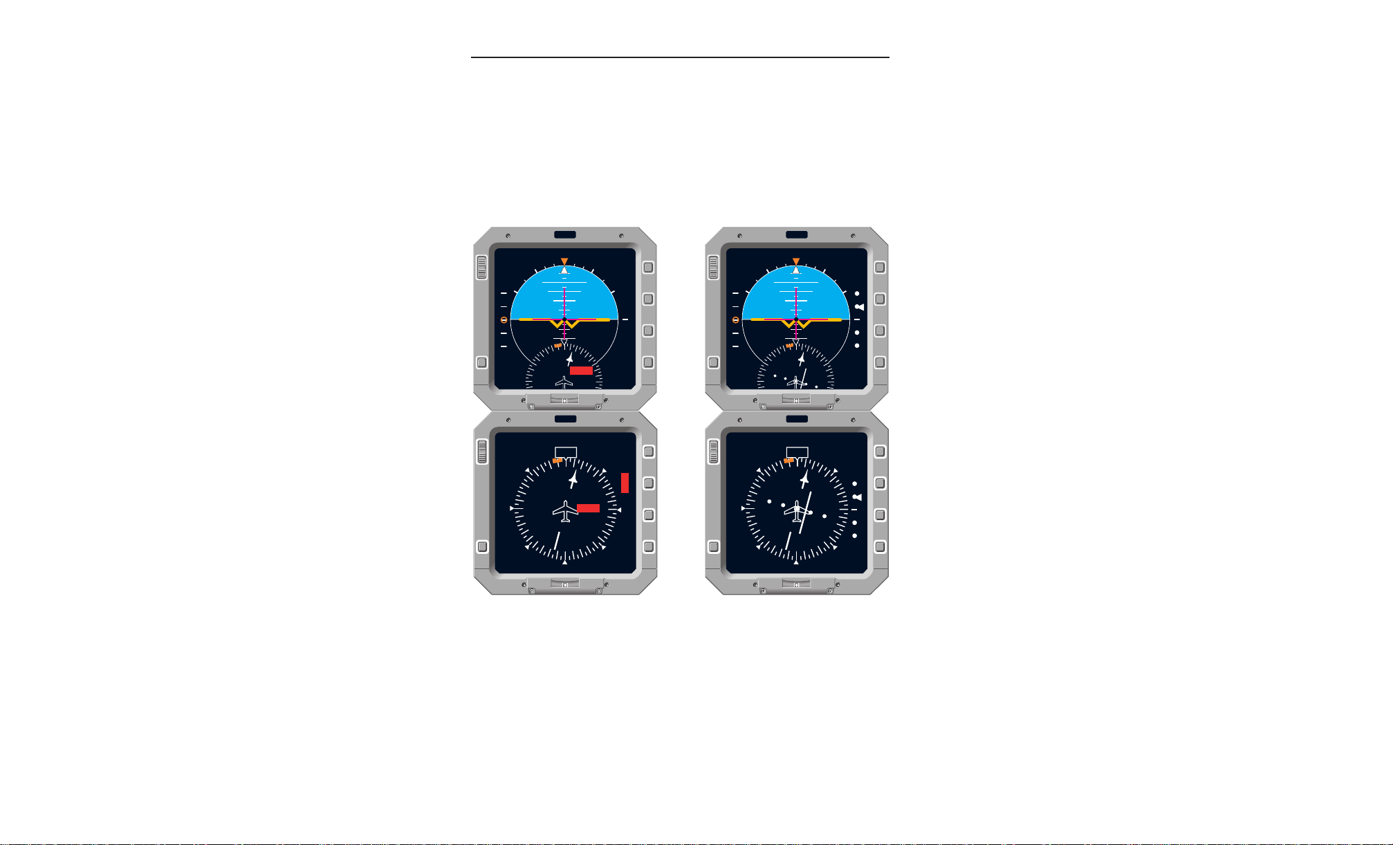
5.2.1 ADI SELF TEST
Press and hold the TEST button on the ADI to initiate the three phases of self test. Release of the button will cause the previous display to
return, unless BIT test is in progress, in which case the test will complete, then the display will return.
A
Phase 1 -
for five seconds.
• No failure flags displayed
• Attitude - 10° pitch up, 20° right roll
• Flight Director - Full scale (16.7°) pitch up, full scale (16.7°) right roll
• Rudder Command - Full scale right
• Glideslope - Centered
• Speed Command - Centered
• Rate of Turn - Centered
• Rising Runway - Centered laterally, 100 feet radio altitude
Phase 2 -
• Ground - Decluttered
• Pitch Scale - Decluttered
• Roll Sky Pointer - Decluttered
• SPD, GYRO, GS, R/T, RWY flags
• FD light - On steady
• DH light - On steady
• CM annunciations - Appear only if configured
• All flags except FD and DH flashing
A static display that imitates the electromechanical self test
All failure and warning flags flashing for five seconds.
Phase 3 Same as Phase 2 except flags remain on steady
5-2
Steady flags displayed while internal BIT test performed.
FPD 500 FLAT PANEL DISPLAY SYSTEM
Rev. 0
Jan/97
Page 47

A
N
M
R
I
DIM
TEST
BRT
10
2020
10
55
3030
55
1010
F
S
GS
TEST
MON
N
M
R
I
DIM
TEST
BRT
TEST
FD DH
2
MON
HDG PIT ROL GS LOC
ALT
S
P
D
GYRO
FD
RWY
R/T
G
S
Operating Instructions
Figure 4.1-2
ADI Self Test Phase 1
Rev. 0
Jan/97
ADI Self Test Phase 2 & 3
Figure 4.1-3
FPD 500 FLAT PANEL DISPLAY SYSTEM
5-3
Page 48

Operating Instructions
5.2.2 HSI SELF TEST
Press and hold the TEST button on the HSI to initiate the three phases of self test. Release of the button will cause the previous display to
return, unless BIT test is in progress, in which case the test will complete, then the display will return.
A
Phase 1 -
for five seconds.
• No failure flags displayed
• Compass Card - 0° (north), digital heading “000”
• Source/Distance Display - INSX/3999; or DMEX/399.9 if available,
• Glideslope - Centered
• Selected Course - 90°
• Lateral Deviation - Centered
• TO/FROM - Both displayed
• Heading Bug - 180°
If ARC or MAP mode:
•Off Scale Symbols - Both heading bug and course pointer displayed
Phase 2 -
• Source/Distance Display - Decluttered
• Selected Course - Decluttered
• Lateral Deviation - Decluttered
• TO/FROM - Decluttered
• Heading Bug - Decluttered
• Digital Heading/Lubber Mark - Decluttered
A static display that imitates the electromechanical self test
if not available, then blank
All failure and warning flags flashing for five seconds.
Phase 3 Same as Phase 2 except flags remain on steady
5-4
Steady flags displayed while internal BIT test performed.
FPD 500 FLAT PANEL DISPLAY SYSTEM
Rev. 0
Jan/97
Page 49

A
N
M
R
I
DIM
TEST
BRT
0
33
30
27
24
21
15
12
9
6
3
18
000
GS
NAV 1
INS1
3999
INS2
3999
TEST
N
M
R
I
DIM
TEST
BRT
0
33
30
27
24
21
15
12
9
6
3
18
NAV 1
HDG
G
S
NAV
A
L
E
R
T
TEST
N
M
R
I
DIM
TEST
BRT
0
33
6
3
000
GS
NAV 1
INS1
3999
INS2
3999
ARC
TEST
N
M
R
I
DIM
TEST
BRT
0
33
6
3
NAV 1
ARC
TEST
HDG
G
S
NAV
A
L
E
R
T
Operating Instructions
Figure 4.1-4
Normal HSI Self Test Phase 1
Rev. 0
Jan/97
Normal HSI Self Test Phase 2 & 3
Figure 4.1-7
FPD 500 FLAT PANEL DISPLAY SYSTEM
ARC HSI Self Test Phase 1
ARC HSI Self Test Phase 2 & 3
Figure 4.1-5
Figure 4.1-8
5-5
Page 50

Operating Instructions
5.2.3 INTEGRATE MODE SELF TEST
Press and hold the TEST button on the ADI/HSI to initiate the three
phases of self test. Release of the button will cause the previous display to return, unless BIT test is in progress, in which case the test
will complete, then the display will return.
A
Phase 1 -
A static display that imitates the electromechanical self test
for five seconds.
• No failure flags displayed
• Compass Card - 0° (north)
• Source/Distance Display - INSX/3999; or DMEX/399.9 if available,
• Glideslope & Later al Deviation - Centered
• Selected Course - 90°
• TO/FROM - Both displayed
• Heading Bug - 180° (out of view)
• Off Scale Symbols - Both heading bug and course pointer displayed
• Attitude - 10° pitch up, 20° right roll
• Flight Director - Full scale (16.7°) pitch up, full scale (16.7°) right roll
• Rudder Command - Full scale right
• Glideslope & Speed Command - Centered
Phase 2 -
• Source/Distance Display - Decluttered
• Selected Course & Lateral Deviation - Decluttered
• TO/FROM - Decluttered
• Heading Bug - Decluttered
• Lubber Mark - Decluttered
• Ground - Decluttered
• Pitch Scale - Decluttered
• Roll Sky Pointer - Decluttered
• SPD, GYRO, GS, R/T, RWY flags
• FD light - On steady
• DH light - On steady
• CM annunciations - Appear only if configured
• All flags except FD and DH flashing
if not available, then blank
All failure and warning flags flashing for five seconds.
Phase 3 Same as Phase 2 except flags remain on steady
5-6
Steady flags displayed while internal BIT test performed.
FPD 500 FLAT PANEL DISPLAY SYSTEM
Rev. 0
Jan/97
Page 51

A
N
M
R
I
DIM
TEST
BRT
10
2020
10
55
3030
55
1010
F
S
GS
TEST
0
33
30
27
9
6
3
NAV 1
INS1
1234
INS2
1324
N
M
R
I
DIM
TEST
BRT
TEST
0
33
30
27
9
6
3
FD DH
NAV 1
S
P
D
GYRO
FD
HDG
NAV
G
S
2
A
L
E
R
T
Operating Instructions
Figure 4.1-10
Integrate Mode Self Test Phase 1
Rev. 0
Jan/97
Integrate Mode Self Test Phase 2 & 3
Figure 4.1-11
FPD 500 FLAT PANEL DISPLAY SYSTEM
5-7
Page 52

Operating Instructions
A
5.3 LIMITATIONS
For information on EADI/EHSI system operating limitations, please
refer to the approved Flight Manual Supplement for the particular aircraft in question.
5.4 EMERGENCY PROCEDURES
For information on EADI/EHSI system emergency procedures,
please refer to the approved Flight Manual Supplement for the particular aircraft in question.
5-8
FPD 500 FLAT PANEL DISPLAY SYSTEM
Rev. 0
Jan/97
Page 53

A
Maintenance Mode Displays
6. MAINTENANCE MODE DISPLAYS
The maintenance mode provides access to the display’s internal
operating parameters and fault status. The maintenance mode may
be accessed by pressing the TEST and Integrate (I) buttons simultaneously. Data is displayed on multiple pages. The “Next” page is
selected using the Range (R) pushbutton. The last page wraps
around to the first page. Pressing the Normal (N) button exits the
maintenance mode. The maintenance mode is inhibited during the
ILS mode if glideslope and localizer are both valid.
NOTE: The maintenance pages are intended to aid troubleshooting
on the ground. They are not intended for use in flight.
The first maintenance page contains the current software version and
mod level, unit serial number, and part number, as well as the
AlliedSignal copyright information. Page 2 begins the unit operating
parameters. The following maintenance pages shall be displayed:
• FPI-3501B MAINTENANCE PG 01
• DU OPERATING PARAMS PG 02
• DU STATUS PG 03
• DU BEZEL STATUS PG 04
• DU INTERFACE STATUS PG 05
• DU INTERFACE STATUS PG 06
• DU INTERFACE STATUS PG 07
• DU INTERFACE STATUS PG 08
• DU INTERFACE STATUS PG 09
• DU INTERFACE STATUS PG 10
• DU CALIBRATION DATA PG 11
• WHITE FLAT FIELD TEST PATTERN PG 12
• RED FLAT FIELD TEST PATTERN PG 13
• GREEN FLAT FIELD TEST PATTERN PG 14
• BLUE FLAT FIELD TEST PATTERN PG 15
• BLACK FLAT FIELD TEST PATTERN PG 16
• GRAY SHADES FOR WHITE, RED, GREEN, BLUE PG 17
• WATCHDOG TIMER TEST PG 18
Rev. 0
Jan/97
FPD 500 FLAT PANEL DISPLAY SYSTEM
6-1
Page 54

Maintenance Mode Displays
N
M
R
I
DIM
TEST
BRT
DU OPERATING PARAMS PG 02
INTERNAL TEMPERATURE 38 °C
EXTERNAL LIGHT LEVEL 120
DISPLAY BRIGHTNESS 25.46 FL
BURST CONTROL OUTPUT 23.50 %
DIM/HV OUTPUT 0.00 V
LAMP HEATER OFF
LCD HEATER OFF
TOTAL POWER CYCLES 303
TOTAL TIME 64 HRS
POWER CYCLE TIME 0 HRS 11 MINS
ITEST
FREEZE
N
M
R
I
DIM
TEST
BRT
FPI-3501B MAINTENANCE PG 01
COPYRIGHT
ALLIEDSIGNAL AVIONICS INC. 1995
SW RELEASE 01/2H ID 1230960925
BOOT RELEASE 01/02
S/N 0021
P/N 066-50017-0101
INSTALL/CONFIGURATION OPTIONS
A/C TYPE DC-10
A/C SIDE CAPT
DISPLAY TYPE HSI
CM ANNUNCIATIONS OFF
FD CMD IN VIEW HI
PITCH CMD 150
ROLL CMD 150
6.1 MAINTENANCE PAGE 1
The following is the definition of
the states for the page:
Parameter States
A/C TYPE B-727/DC-10
A/C SIDE CAPT/FO
DISPLAY TYPE ADI/HSI
CM ANNUN ON/OFF
FD CMD IN VIEW HI/LO
PITCH CMD 150/120
ROLL CMD 150/66
6.2 MAINTENANCE PAGE 2
The following is the definition of
the states for the page:
A
Figure 6.1-1
Maintenance Page 1
Parameter States
LAMP HEATER ON/OFF
LCD HEATER ON/OFF
Figure 5.2-1
A red flashing “FREEZE” annun-
Maintenance Page 2
ciation indicates that the status
annunciations are static with no
update, frozen by pressing the
Mode (M) button.
Figure 6.2-2
Frozen Maintenance Page 2
6-2
FPD 500 FLAT PANEL DISPLAY SYSTEM
Rev. 0
Jan/97
Page 55

A
N
M
R
I
DIM
TEST
BRT
DU BEZEL STATUS PG 04
BRT PUSHBUTTON 0
DIM PUSHBUTTON 0
N PUSHBUTTON 0
M PUSHBUTTON 0
R PUSHBUTTON 0
I PUSHBUTTON 0
TEST PUSHBUTTON 0
N
M
R
I
DIM
TEST
BRT
DU STATUS PG 03
LAMP PASS
IP PASS
GP PASS
POWER SUPPLY PASS
DIMMER/LCD PASS
I/O #1 PASS
I/O #2 PASS
BEZEL PASS
6.3 MAINTENANCE PAGE 3
The following is the definition of
the states for the page:
Parameter States
LAMP REPLACE/
PASS/FAIL
IP, GP,ETC. PASS/FAIL
Maintenance Mode Displays
Figure 6.3-1
Maintenance Page 3
6.4 MAINTENANCE PAGE 4
The following is the definition of
the states for the page:
Parameter States
PUSHBUTTON 0/1
NOTE: Remember, if you are
testing the buttons, that pressing
the R button will advance to the
next page, and pressing the N
button will exit the maintenance
mode.
Figure 6.4-1
Rev. 0
Jan/97
FPD 500 FLAT PANEL DISPLAY SYSTEM
Maintenance Page 4
6-3
Page 56

Maintenance Mode Displays
N
M
R
I
DIM
TEST
BRT
DU INTERFACE STATUS PG 06
DISCRETE HI INPUT 0 HI
DISCRETE LO INPUT 0 LO
DISCRETE HI INPUT 1 HI
DISCRETE LO INPUT 1 LO
DISCRETE HI INPUT 2 HI
DISCRETE LO INPUT 2 LO
DISCRETE HI INPUT 3 HI
DISCRETE LO INPUT 3 LO
DISCRETE HI INPUT 4 HI
DISCRETE LO INPUT 4 LO
DISCRETE HI INPUT 5 HI
DISCRETE LO INPUT 5 LO
N
M
R
I
DIM
TEST
BRT
DU INTERFACE STATUS PG 05
429 TX INACTIVE
429 RX 1 INACTIVE
429 RX 2 INACTIVE
561/568 RX 1 INACTIVE
561/568 RX 2 INACTIVE
SYNCHRO INPUT 1 000
SYNCHRO INPUT 2 180
SYNCHRO INPUT 3 180
SYNCHRO INPUT 4 360
SYNCHRO INPUT 5 000
6.5 MAINTENANCE PAGE 5
The following is the definition of
the states for the page:
Parameter States
429 TX/RX ACTIVE/
INACTIVE
561/568 RX ACTIVE/
INACTIVE
SYNCHRO ANGLE
DATA
VALUE
A
Figure 6.5-1
Maintenance Page 5
6.6 MAINTENANCE PAGE 6
The following is the definition of
the states for the page:
Parameter States
DISCRETE HI HI/OPEN
DISCRETE LO OPEN/LO
Figure 6.6-1
6-4
FPD 500 FLAT PANEL DISPLAY SYSTEM
Maintenance Page 6
Rev. 0
Jan/97
Page 57

A
N
M
R
I
DIM
TEST
BRT
DU INTERFACE STATUS PG 08
DISCRETE INPUT 12 OPEN
DISCRETE INPUT 13 LO
DISCRETE INPUT 14 OPEN
DISCRETE INPUT 15 OPEN
DISCRETE INPUT 16 LO
DISCRETE INPUT 17 OPEN
DISCRETE INPUT 18 LO
DISCRETE INPUT 19 LO
N
M
R
I
DIM
TEST
BRT
DU INTERFACE STATUS PG 07
DISCRETE HI INPUT 6 HI
DISCRETE LO INPUT 6 OPEN
DISCRETE HI INPUT 7 HI
DISCRETE LO INPUT 7 LO
DISCRETE HI INPUT 8 OPEN
DISCRETE LO INPUT 8 OPEN
DISCRETE HI INPUT 9 OPEN
DISCRETE LO INPUT 9 OPEN
DISCRETE HI INPUT 10 OPEN
DISCRETE LO INPUT 10 OPEN
DISCRETE HI INPUT 11 HI
DISCRETE LO INPUT 11 LO
6.7 MAINTENANCE PAGE 7
The following is the definition of
the states for the page:
Parameter States
DISCRETE HI HI/OPEN
DISCRETE LO OPEN/LO
Maintenance Mode Displays
Figure 6.7-1
Maintenance Page 7
6.8 MAINTENANCE PAGE 8
The following is the definition of
the states for the page:
Parameter States
DISCRETE OPEN/LO
Figure 6.8-1
Rev. 0
Jan/97
FPD 500 FLAT PANEL DISPLAY SYSTEM
Maintenance Page 8
6-5
Page 58

Maintenance Mode Displays
N
M
R
I
DIM
TEST
BRT
DU INTERFACE STATUS PG 10
DISCRETE OUTPUT 0 LO
DISCRETE OUTPUT 1 LO
DISCRETE OUTPUT 2 LO
DISCRETE OUTPUT 3 LO
DISCRETE OUTPUT 4 LO
DISCRETE OUTPUT 5 LO
DISCRETE OUTPUT 6 LO
DISCRETE OUTPUT 7 LO
N
M
R
I
DIM
TEST
BRT
DU INTERFACE STATUS PG 09
ANALOG CHANNEL 0 -.026 V
ANALOG CHANNEL 1 -.003 V
ANALOG CHANNEL 2 -1.137 V
ANALOG CHANNEL 3 -1.138 V
ANALOG CHANNEL 4 -.001 V
ANALOG CHANNEL 5 -.017 V
ANALOG CHANNEL 6 .010 V
ANALOG CHANNEL 7 -.000 V
ANALOG CHANNEL 8 .000 V
ANALOG CHANNEL 9 -1.977 V
ANALOG CHANNEL 10 1.276 V
ANALOG CHANNEL 11 1.301 V
6.9 MAINTENANCE PAGE 9
The following is the definition of
the states for the page:
Parameter States
ANALOG DATA Value
A
Figure 6.9-1
Maintenance Page 9
6.10 MAINTENANCE PAGE 10
The following is the definition of
the states for the page:
Parameter States
DISCRETE OUT HI/LO
Figure 6.10-1
6-6
FPD 500 FLAT PANEL DISPLAY SYSTEM
Maintenance Page 10
Rev. 0
Jan/97
Page 59

A
N
M
R
I
DIM
TEST
BRT
DU CALIBRATION DATA PG 11
TEMPERATURE CORRECTED DATA
INTERNAL TEMPERATURE 46 °C
CALIBRATED LIS VALUE = 105743
VCOM = 3742
T0P = 3839 T4P = 1005
T0N = 4 T4N = 3664
T1P = 1398 T5P = 883
T1N = 3036 T5N = 3826
T2P = 1229 T6P = 768
T2N = 3306 T6N = 4030
T3P = 1098 T7P = 0
T3N = 3517 T7N = 4080
FREEZE
CALIBRATION
POINT
N
M
R
I
DIM
TEST
BRT
DU CALIBRATION DATA PG 11
NON VOLATILE DATA
LIS CALIBRATION VALUE = 42277
VCOM = 3824
T0P = 3839 T4P = 1312
T0N = 4 T4N = 2912
T1P = 2032 T5P = 1168
T1N = 2096 T5N = 3136
T2P = 1680 T6P = 1008
T2N = 2448 T6N = 3376
T3P = 1472 T7P = 0
T3N = 2704 T7N = 4080
CALIBRATION
POINT
6.11 MAINTENANCE PAGE 11
The following is the definition of
the states for the page:
Parameter States
ANALOG DATA Value
The LIS data displayed may be
either current or stored nonvolatile data, selected by pressing the Integrate (I) button. The
current values will alternate
between frozen and real time by
pressing the Mode (M) button.
Maintenance Mode Displays
Figure 6.11-1
Maintenance Page 11
Non-Volatile Data
Figure 6.11-2
Maintenance Page 11
Current Data
Rev. 0
Jan/97
FPD 500 FLAT PANEL DISPLAY SYSTEM
6-7
Page 60

Maintenance Mode Displays
N
M
R
I
DIM
TEST
BRT
N
M
R
I
DIM
TEST
BRT
6.12 MAINTENANCE PAGE 12
Pages 12 - 17 are a check of the
primary colors (white, red, green,
blue, black) on the display.
A
Figure 6.12-1
Maintenance Page 12
6.13 MAINTENANCE PAGE 13
Pages 12 - 17 are a check of the
primary colors (white, red, green,
blue, black) on the display.
Figure 6.13-1
6-8
FPD 500 FLAT PANEL DISPLAY SYSTEM
Maintenance Page 13
Rev. 0
Jan/97
Page 61

A
N
M
R
I
DIM
TEST
BRT
N
M
R
I
DIM
TEST
BRT
6.14 MAINTENANCE PAGE 14
Pages 12 - 17 are a check of the
primary colors (white, red, green,
blue, black) on the display.
Maintenance Mode Displays
Figure 6.14-1
Maintenance Page 14
6.15 MAINTENANCE PAGE 15
Pages 12 - 17 are a check of the
primary colors (white, red, green,
blue, black) on the display.
Figure 6.15-1
Rev. 0
Jan/97
FPD 500 FLAT PANEL DISPLAY SYSTEM
Maintenance Page 15
6-9
Page 62

Maintenance Mode Displays
N
M
R
I
DIM
TEST
BRT
N
M
R
I
DIM
TEST
BRT
6.16 MAINTENANCE PAGE 16
Pages 12 - 17 are a check of the
primary colors (white, red, green,
blue, black) on the display.
A
Figure 6.16-1
Maintenance Page 16
6.17 MAINTENANCE PAGE 17
Pages 12 - 17 are a check of the
primary colors (white, red, green,
blue, black) on the display. This
one checks the gray shades of
white, red, green, and blue.
Figure 6.17-1
6-10
FPD 500 FLAT PANEL DISPLAY SYSTEM
Maintenance Page 17
Rev. 0
Jan/97
Page 63

A
N
M
R
I
DIM
TEST
BRT
WATCHDOG TIMER STATUS PG 18
N/D
6.18 MAINTENANCE PAGE 18
This page contains “Watchdog
Timer Test” information. This test
is currently disabled and only displays “N/D”.
Maintenance Mode Displays
Figure 6.18-1
Maintenance Page 18
Rev. 0
Jan/97
FPD 500 FLAT PANEL DISPLAY SYSTEM
6-11
Page 64

Maintenance Mode Displays
A
This page intentionally left blank.
6-12
FPD 500 FLAT PANEL DISPLAY SYSTEM
Rev. 0
Jan/97
Page 65

Printed .2K 8/97 CW
AlliedSignal, Inc.
Commercial Avionics Systems
400 North Rogers Road
Olathe, KS USA 66062-1294
FAX: 913-791-1302
Telephone: 913-782-0400
006-18046-0000
Rev. 0 1/97
A
 Loading...