

Page 1
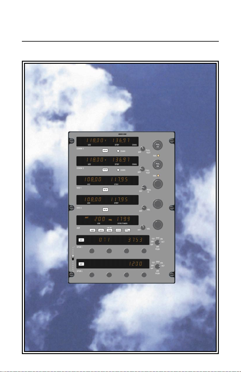
Pilot’s Guide CNI 5000
Integrated Avionics System
N
Page 2

Table of Contents
Introduction ..........................................................................................2
System Components ............................................................................3
Operating Instructions-COMM .............................................................4
Power Up....................................................................................4
Transmitting................................................................................4
Frequency Mode.........................................................................5
Program Mode............................................................................5
Program-Secure Mode...............................................................5
Channel Mode............................................................................6
Direct Tune mode.......................................................................6
Default Mode..............................................................................6
Display Adjust Mode...................................................................6
Operating Instructions-NAV.................................................................8
Power Up....................................................................................8
Frequency Selection...................................................................8
Nav Frequency Operation ..........................................................8
Operating Instructions-ADF .................................................................9
Power Up....................................................................................9
Frequency Selection...................................................................9
Operating Modes........................................................................9
ADF Test ..................................................................................10
Operating the Timers................................................................10
Erroneous ADF Bearings
Station Overlap..................................................................11
Electrical Storms................................................................11
Night Effect ........................................................................11
Mountain Effect..................................................................11
Coastal Refraction .............................................................11
Operating Instructions-MODE S.........................................................12
Front Panel Operation..............................................................12
Function Selector (Modes of Operation)...................................13
XPDR 1 / XPDR 2 Switch.........................................................14
Display Adjust Mode.................................................................14
1
Page 3

Introduction
The CNI 5000 is a compact and light
weight Integrated Avionics System
designed especially for the sophisticated
environment of today’s cockpit.
The integrated design of the CNI 5000
provides the pilot with full-featured
COMM/NAV/IDENT capability in a single
unit. With large, self-dimming gas-discharge displays, the CNI 5000 is easy to
read from virtually any viewing angle in the
cockpit. COMMs, NAVs, and ADF feature
“flip-flop” frequency preselection which
gives the pilot the ability to set up en route
or approach frequency changeovers well in
advance of the actual transition point or
ATC handoff sequence for true “stayahead” flight management.
Innovative non-volatile memory circuits
hold all displayed frequencies in storage—
through aircraft shutdowns or momentary
power interruptions—without the need for
battery power of any kind.
Seven modules make up the CNI 5000.
These include two COMMs, two NAVs, an
ADF and two Transponders (XPDR). The
modular architecture of the CNI 5000
makes it possible to replace a COMM,
NAV, ADF or XPDR portion of the system
with out complete removal of the CNI unit.
Each STANDARD COMM is capable of
tuning 760 frequencies from 118.000MHz
to 136.975MHz with frequency spacing of
25kHz. An optional COMM package is
available with each COMM capable of tuning 2280 frequencies from 118.0000 MHz
to 136.9916 MHz with frequency spacing of
8.33 kHz. An audio-leveling feature automatically amplifies weak audio signals and
mutes signals that are too strong. A safety
feature of the CNI 5000 COMMs is the
stuck-microphone indicator. If the mic is
keyed for more than two minutes, the display will begin to flash, and the unit will
cease transmitting. This alerts you to the
problem while it prevents you from inadvertently jamming a frequency and making it
unusable to other pilots.
The versatile NAVs will tune all 200
VOR/LOC frequencies in addition to the 40
glideslope frequencies. Output is also provided for automatic changing of the remote
DME system.
The ADF receiver provides accurate
bearing to stations in the 200kHz to
1799kHz frequency range. Complete ADF,
ANT and BFO tuning modes are provided,
along with audio output for station identification and monitoring of AM broadcasts.
It’s advanced “coherent detection”
design rejects unwanted interference,
achieves significantly greater range and
has less susceptibility to engine noise, static, and atmospheric interference.
The standard CNI 5000 offers dual
Mode S transponders. A version of the
CNI 5000 is also available with dual
ATCRBS Transponders for special international applications.
The new Mode S (Mode Select)
transponders are designed to provide ATC
with improved aircraft surveillance and
reporting accuracy, and reduce interference in identity and altitude reporting.
These improvements are made possible be
cause each aircraft is assigned a unique
address code. By using this code in the
form of a discrete addressing system, a
Mode S ground installation is able to
selectively interrogate a specific aircraft,
even in high-density situations. This significant improves the ability of ATC to monitor
and direct your aircraft—along with those
around it. Offering full Mode A and Mode C
compatibility, Mode S meets all current
ATCRBS technical requirements.
The CNI 5000 Mode S and ATCRBS
Transponders feature digital display of
encoded altitude and ATC code, push button selection of VFR code, remote-ident
switch capability, and a XPDR 1/2 Select
Switch for quick selection of either
transponder.
The CNI 5000 offers state-of-the-art
technology and pilot-preferred features to
significantly increase cockpit efficiency and
decrease pilot workload.
This Pilots Guide covers basic operating procedures of the CNI 5000 by function,
i.e. COMM, NAV, ADF and XPDR. Simple
operation and the ease with which you can
learn to use it serve to enhance it’s performance and capabilities.
2
Page 4
XPDR Switch
selects which
transponder is
active
USE STBY
COMM 1
USE STBY CHAN
COMM 2
USE STBY
NAV 1
USE STBY
NAV 2
ADF
ADF
IDT
XPDR 1
IDT
XPDR 2
BFO FLT
USE STBY/TIMER
ADF
BFO FRQ
FL
071
FL
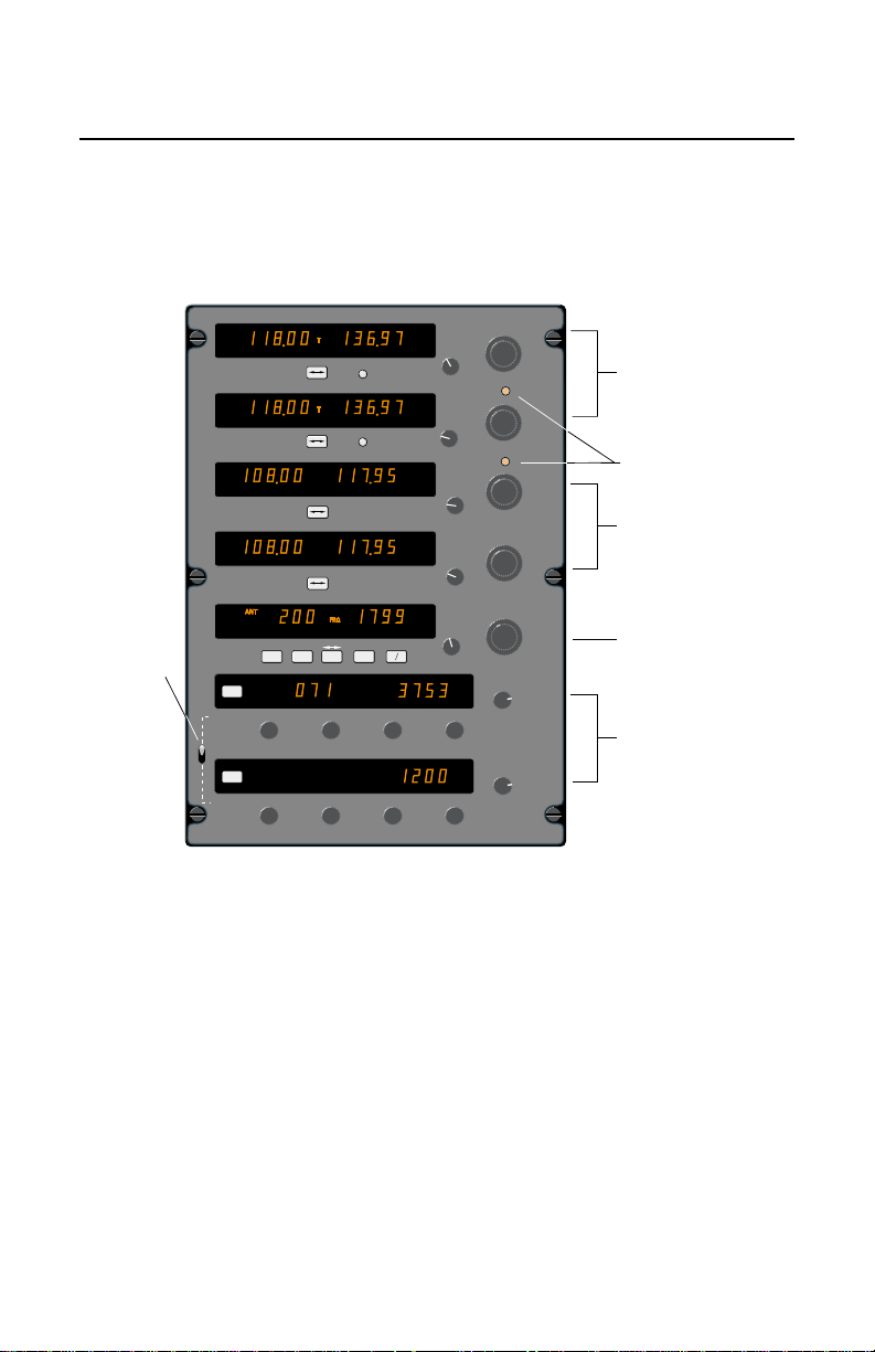
System Components
ı
Dual 760 or optional 2280
frequency COMM tranceivers,
each with nine pilot-programable channels.
Fan-Fail Annunciators
provide warning of internal
cooling fan failure.
Dual NAV Receivers that
will tune 200 VOR/LOC
channels and 40 Glideslope
channels.
Full-featured ADF Receiver
tunes 200 kHz to 1799 kHz.
Also has multi-function
flight timer.
Dual Mode S Transponders
with 4096 codes plus
digital displays of encoded
altitude.
ET/FLT
ON
ALT R
GND SBY
ON
ALT
GND SBY
CHAN
CHAN
CHAN
ET
SET
RST
R
PULL
25K
PULL
OFF
TEST
FAN
PULL
25K
PULL
OFF
TEST
FAN
PULL
OFF
ID
VOL
OFF
VOL
OFF
GND
TST
ON
SBY
ALT
OFF
VFR
PUSH
GND
TST
ON
SBY
ALT
OFF
VFR
PUSH
NAV
The CNI 5000 is a complete CNI package
that includes dual COMMs, dual NAVs, single ADF and dual Mode S transponders.
The unit features easy-to-read gas-discharge displays. COMMs, NAVs and ADF
feature “flip-flop” tuning for push button frequency preselection. Dual Mode S
transponders offer state-of-the-art ATC
identification. The XPDR 1/2 switch selects
the active transponder. The unit’s lighting
operates off the aircraft dimming bus.
The CNI 5000 uses internal and external
cooling fans to provide forced air cooling
for optimum reliability. In the unlikely event
of a fan failure, integrated Fan Fail
Annunciators on the face of the CNI 5000
alert the pilot when an internal (FAN 1) or
external (FAN 2) cooling fan has failed.
Detailed operating instructions for each of
the systems that comprise the CNI 5000
are given on the following pages.
3
Page 5
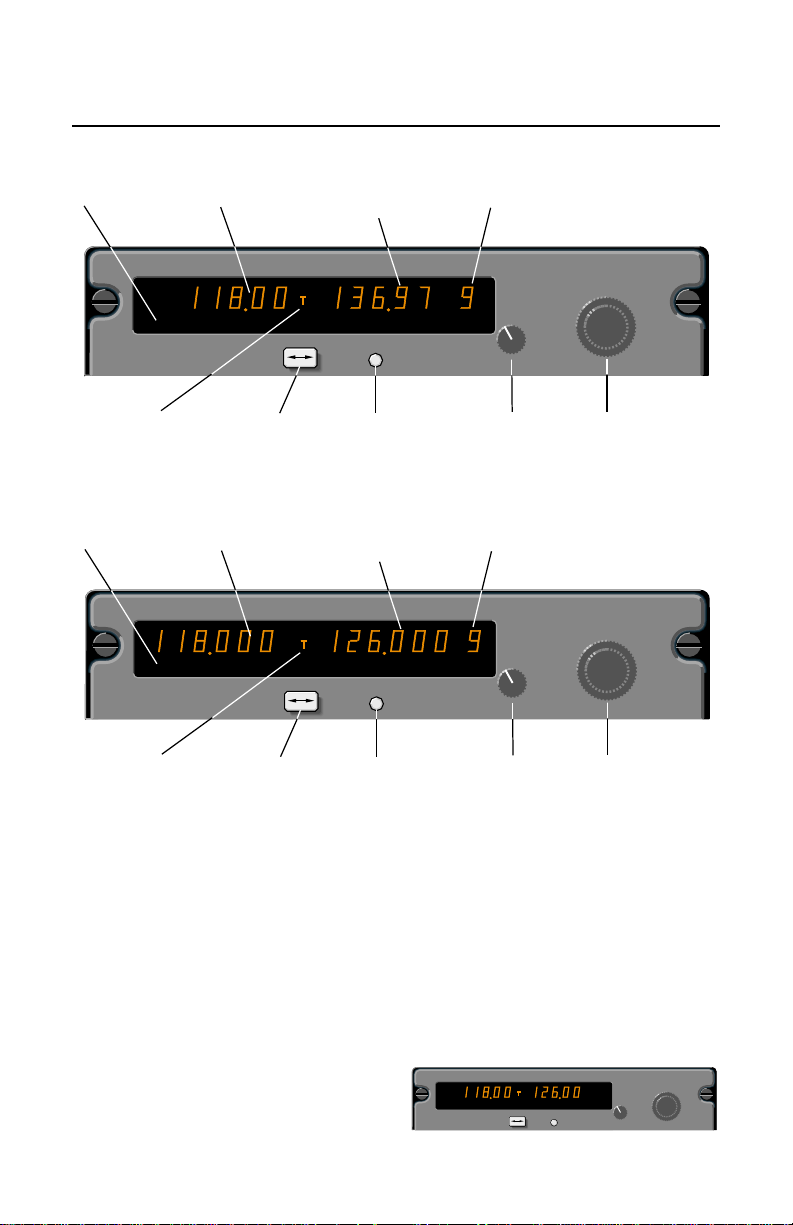
Operating Instructions - COMM
Standard COMM (25 kHz Frequency Spacing)
Photocell for
automatic
dimmimg
"USE" window
shows active
frequency
"STBY" window
shows stored
or newly-entered
standby frequencies
"CHAN" window
shows selected
channel number
USE STBY
COMM 1
"T" indicates
mike button is
depressed for
transmission
Frequency transfer
"flip-flop" button
Optional COMM (8.33 kHz Frequency Spacing)
Photocell for
automatic
dimmimg
COMM 1
"T" indicates
mike button is
depressed for
transmission
"USE" window
shows active
frequency
USE STBY
Frequency transfer
"flip-flop" button
"STBY" window
shows stored
or newly-entered
standby frequencies
The CNI 5000 has two identical
COMM transceivers. Each standard
COMM is capable of tuning 760 frequencies from 118.000 MHz to 136.975 MHz
with frequency spacing of 25 kHz. An
optional COMM package is available with
each COMM capable of tuning 2280 frequencies from 118.0000 MHz to 136.9916
MHz with frequency spacing of 8.33 kHz.
The following operating instructions apply
to COMM 1 and COMM 2.
Power Up.
When you turn the ON/OFF/ Volume
knob clockwise to the “ON” position, your
unit will display the frequencies last used in
CHAN
Channel button
CHAN
Channel button
CHAN
OFF
ON/OFF/Volume
control switch. Pull
out for manual
squelch override.
"CHAN" window
shows selected
channel number
CHAN
OFF
ON/OFF/Volume
control switch. Pull
out for manual
squelch override.
PULL
TEST
PULL
TEST
PULL
25K
Frequency
selector knobs
PULL
8.33K
Frequency
selector knobs
the “USE” and “STBY” (standby) windows.
To override the automatic squelch, pull
the ON/OFF/Volume knob out and, judging
by the static noise, rotate it to the desired
volume level. Push the knob back in to
activate the automatic squelch.
Transmitting.
During COMM transmissions, a “T” will
appear between the “USE” and “STBY”
windows to indicate the keying of the
microphone.
USE STBY
COMM 1
CHAN
CHAN
PULL
25K
PULL
OFF
TEST
4
Page 6
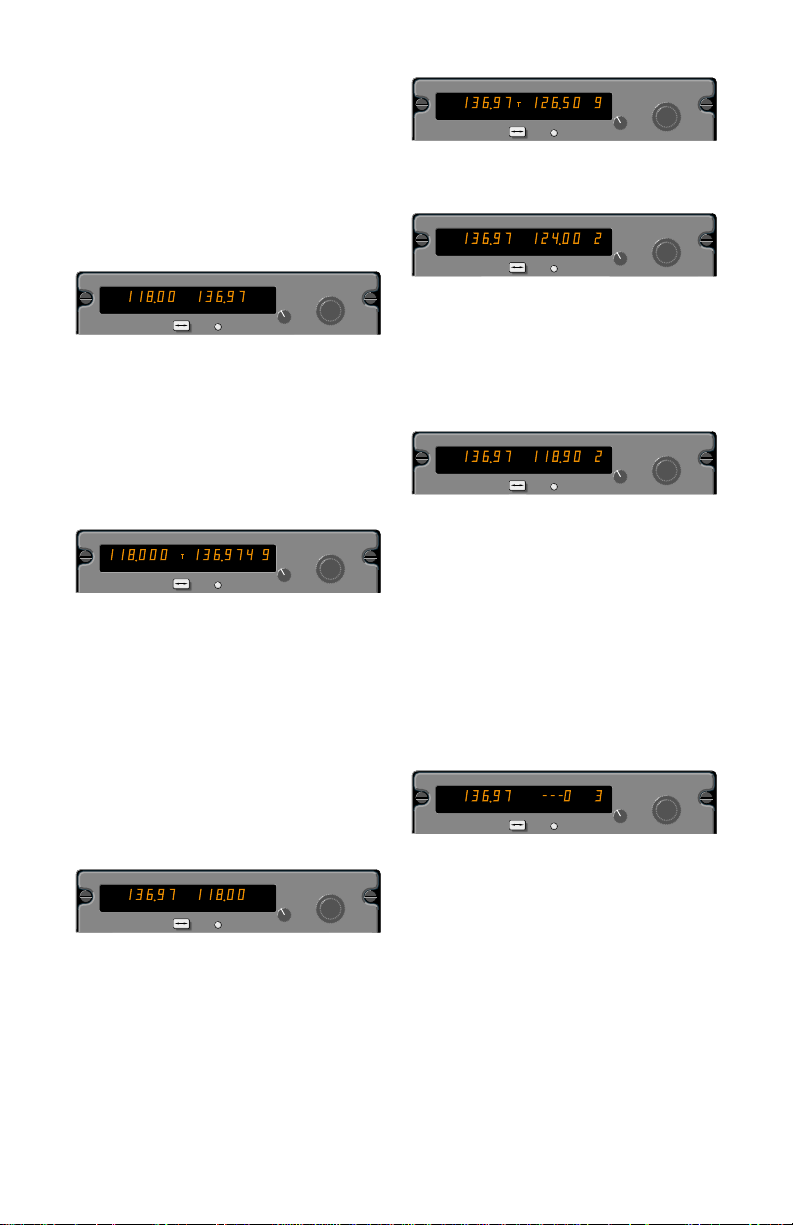
The Frequency Mode (Normal Operation).
Standard COMM
1a. Select a new frequency in the “STBY”
window, using the frequency selection
knobs. The larger knob controls changes in
increments of 1MHz. The smaller knob controls changes in increments of 50kHz when
pushed in, and 25kHz when pulled out.
Proceed to Step 2.
USE STBY
COMM 1
T
CHAN
CHAN
PULL
25K
PULL
OFF
TEST
Optional COMM
1b. Select a new frequency in the “STBY”
window, using the frequency selection
knobs. The larger knob controls changes in
increments of 1MHz. The smaller knob controls changes in increments of 25kHz when
pushed in, and 8.33kHz when pulled out.
Proceed to Step 2.
USE STBY
COMM 1
CHAN
CHAN
PULL
8.33K
PULL
OFF
TEST
NOTE: On both the standard and optional
COMM, the outside limits of the band, the
display will “wrap around” to the other end
of the band, going from 136MHz to 118MHz.
2. Press the transfer button to activate the
new frequency. The newly entered frequency in the “STBY” window flip-flops with
the frequency in the “USE” window. This
new frequency is now available for use. An
optional remote-mounted frequency transfer button may also be used to perform this
flip-flop” function.
USE STBY
COMM 1
T
CHAN
CHAN
PULL
25K
PULL
OFF
TEST
Program Mode.
The Program Mode is used to program
frequencies for use in the Channel Mode.
1. Depress the channel (CHAN) button for
more than two seconds, until the channel
number (to the right of the standby frequency) begins flashing. The most recently
used active frequency will remain displayed
in the “USE” window.
USE STBY
COMM 1
CHAN
CHAN
PULL
25K
PULL
OFF
TEST
2. Turning either frequency selection knob
will change the channel.
USE STBY
COMM 1
T
CHAN
CHAN
PULL
25K
PULL
OFF
TEST
3. Once you’ve selected the desired channel number, you may program a new frequency by pressing the transfer button.
This will cause the frequency in the “STBY”
window to flash. The tuning knobs are now
used to enter desired frequency.
USE STBY
COMM 1
T
CHAN
CHAN
PULL
25K
PULL
OFF
TEST
4. To program additional channels, push
the transfer button again to make the channel number flash, and repeat steps two and
three above.
5. If you wish to program fewer than nine
channels while skipping certain channel
numbers, rotate the MHz frequency knob
left or right beyond 136MHz or 118MHz.
Dashes (- - -) will appear in the “STBY”
window, indicating that the channel will be
skipped when the system is operating in
the Channel Mode.
USE STBY
COMM 1
T
CHAN
CHAN
PULL
25K
PULL
OFF
TEST
6. To exit the Program Mode, momentarily
press the channel button. The unit will also
automatically exit the Program Mode if no
programming occurs within approximately
20 seconds.
The Program-Secure Mode.
The Program-Secure Mode may be
used to lock a desired frequency to a specific channel number, prohibiting program
changes from the front of the unit. This can
be accomplished by an authorized
Bendix/King Service Center.
5
Page 7

Channel Mode.
The Channel Mode is used to recall
preset frequencies stored in memory.
1. To enter the Channel Mode, momentarily
push the channel (CHAN) button while in
the Frequency Mode. The active frequency
remains displayed in the “USE” window,
and the last used channel number and its
associated frequency are displayed in the
“CHAN” and “STBY” windows.
Direct Tune Mode.
The Direct Tune Mode is entered by
pressing and holding the transfer button for
longer than two seconds. The “STBY” frequency will disappear and the frequency in
the active window can be changed with the
frequency selection knobs.
USE STBY
COMM 1
T
CHAN
CHAN
PULL
25K
PULL
OFF
TEST
USE STBY
COMM 1
T
CHAN
CHAN
PULL
25K
PULL
OFF
TEST
If no channels have been programmed,
channel 1 automatically disappears and
dashes are displayed in the “STBY” window.
2.Turn either frequency selection knob to
change the channel number and the channel’s corresponding frequency in the
“STBY” window.
USE STBY
COMM 1
T
CHAN
CHAN
PULL
25K
PULL
OFF
TEST
3. If there is no activity for five seconds, the
radio will exit the Channel Mode and return
to the Frequency Mode, with the channel
frequency remaining in the “STBY” window.
USE STBY
COMM 1
T
CHAN
CHAN
PULL
25K
PULL
OFF
TEST
4.You can also return to the Frequency
Mode by either:
a. Pressing the channel button before the
five-second delay, in which case the radio
recalls the “USE” and “STBY” frequencies
prior to entering the Channel Mode, or
b. Pressing the transfer button, so that the
channel frequency becomes the active frequency and the last “USE” frequency
becomes the new “STBY” frequency.
Note: If the optional remote channel increment switch is installed, each activation of
the switch will put the unit in the Channel
Mode and advance the channel number
from the previous channel used.
Momentarily pushing the transfer button
will return the unit to the Frequency Mode
(normal operation). The “STBY” frequency
displayed prior to entering the Direct Tune
Mode will return unchanged.
USE STBY
COMM 1
T
CHAN
CHAN
PULL
25K
PULL
OFF
TEST
Default Mode.
Turning on the COMM radio while
pressing the transfer button will bring the
unit up in the Direct Tune Mode and install
120.00 MHz (120.000 MHz on optional
8.33 kHz COMM) as the active frequency.
This will aid the pilot in blind tuning the
radio in the unlikely event of display failure.
USE STBY
COMM 1
T
CHAN
CHAN
PULL
25K
PULL
OFF
TEST
Display Adjust Mode.
To enter the Display Adjust Mode,
press and hold the channel button until the
Program Mode is entered. Continue holding the channel button while simultaneously
pressing and holding the frequency transfer
button until “dA 1” replaces the frequency
USE STBY
COMM 1
T
CHAN
CHAN
PULL
25K
PULL
OFF
TEST
in the “USE” window.
The frequency selector knobs are used to
change the value in the “STBY” window.
Momentarily pressing the channel button
steps the unit through the Display Adjust
6
Page 8

Modes, “dA 1” through “dA 3.” Press the
frequency transfer button to exit the Display
Adjust Mode.
Display Adjustment 1 (dA 1) is used to
vary the dim/bright response time to
changes in ambient light on the display
photocell. The range of values for dA1 is
1-8, with 1 representing normal.
The normal setting, 1, provides immediate display brightness changes when there
are changes in the light falling on the photocell. With dA1 set to a value of 8, the
response time is approximately eight seconds. dA1 values of 2 through 7 provide
intermediate response times.
Display Adjustment 2 (dA 2) is used to
vary the display brightness when ambient
light conditions are less than direct sunlight, such as in a dark cockpit. dA 2 values range from 0-64, with 0 being dimmest
and 64 being brightest; the normal dA 2
setting is 20.
dA 3 values range from 0 to 255, with 0
being the dimmest and 255 being the
brightest. The adjustment varies the
amount of ambient light required for the
display to reach its full dim and bright levels. Normal dA 3 values for a new display
range from 0 to 30.
A common use of dA 3 is to adjust the
COMM display brightness to match the
brightness of the other displays. Another
use is to provide display brightness compensation as the display ages.
7
Page 9

Operating Instructions - NAV
The CNI 5000 has two identical NAV
receivers. The following operating instructions apply to NAV 1 and NAV 2.
Power Up.
Rotate the ON/OFF/VOL/IDENT knob
clockwise from the detented “OFF” position. Power will be activated and the unit
will be ready to operate. Rotation of this
control also adjusts NAV signal volume.
NAV voice may be heard when the knob is
pushed in. When the knob is pulled out,
the Ident signal plus voice may be heard.
Frequency Selection.
By rotating the concentric frequency
selector knobs either clockwise or counterclockwise, the desired operating frequency
can be dialed into the “STBY” (standby)
window. A clockwise rotation will increase
the displayed frequency number, while a
counterclockwise rotation will decrease it.
The larger selector knob is used to change
the MHz portion of the frequency display;
the smaller knob changes the kHz portion
in 50kHz steps. At either band edge of the
108.00 to 117.95 MHz frequency spectrum,
an off-scale rotation will wrap the display
around to the other frequency band-edge
(i.e., 117.95 advances to 108.95 with the
MHz knob rotation, or 117.00 with the kHz
knob rotation). Remote DME and glideslope receivers are also controlled by these
selector knobs.
NAV Frequency Operation.
To tune the NAV receiver to the desired
operating frequency, the selected frequency is first entered into the “STBY” display
and then activated by pushing the transfer
(flip-flop) button. This will interchange the
frequencies in the “USE” and “STBY” displays, and the receiver will now be tuned to
the new operating frequency.
Additionally, this feature makes it possible to pre-select one NAV frequency in the
“STBY” display—and then switch back and
forth between the two frequencies by
pressing the transfer button.
8
Page 10
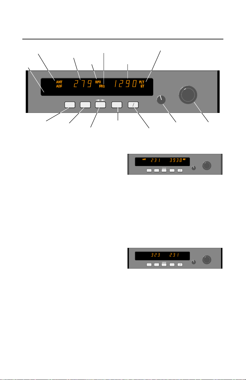
Operating Instructions - ADF
ANT/ADF mode
annunciation
Photocell for
automatic
dimming
Select ANT mode
(out position)
Select ADF mode
(in position)
ADF
"USE" window
shows active
frequency
ADF
Select BFO
STANDBY frequency
annunciation
BFO mode
annunciation
USE STBY/TIMER
BFO FRQ
Frequency transfer
"flip-flop" button
Power Up.
Rotate the ON/OFF/VOL knob clockwise from the detented “OFF” position.
Power will be activated and the unit will be
ready to operate. Rotation of this control
also adjusts audio volume. The CNI 5000
ADF has “audio muting” which causes the
audio output to be muted unless the receiver is locked on a valid station.
Frequency Selection.
The active frequency (to which the ADF
is tuned) is displayed in the left side of the
window at all times. A standby frequency is
displayed in the right side when “FRQ” is
annunciated. The standby frequency is
placed in “blind” memory when either FLT
(Flight Time) or ET (Elapsed Time) mode is
selected.
With “FRQ” annunciated, the standby
frequency is selected using the frequency
select knobs which may be rotated either
clockwise or counterclockwise. Pull the
small inner knob out to tune 1’s. Push the
small inner knob in to tune 10’s. The outer
knob tunes the 100’s and the 1000’s up to
1799kHz.
The standby frequency selected may
then be put into the active window by
pressing the “FRQ” button. The standby
and active frequencies will be exchanged
(flip-flopped), the new frequency will
become active, and the former frequency
will go into standby.
STANDBY frequency,
FLIGHT TIME or
ELAPSED TIME
SET
ET/FLT
Select FLIGHT TIMER
or ELAPSED TIMER
Operating Modes.
annunciated when the “ADF” button is in
the “out” position. ANT provides improved
audio reception from the station tuned and
is usually used for identification. The bearing pointer of the ADF indicator will be
deactivated and immediately turn to 90°
relative position and remain there during
ANT reception.
annunciated when the “ADF” button is in
the depressed position. ADF activates the
bearing pointer in the ADF indicator, causing it to move without hesitation to point in
the direction of the station relative to the
aircraft heading.
Flight Timer and Elapsed Timer
mode annunciation
RST
Set and Reset
ELAPSED TIMER
ADF
ADF
ADF
VOL
OFF
ON/OFF/VOL
control switch
BFO
FRQ ET
USE STBY/TIMER
ET/FLT
BFO FRQ
Frequency
Select Knobs
SET
VOL
RST
OFF
Antenna (ANT) mode is selected and
FLT
ET
SET
ET/FLT
VOL
RST
OFF
ADF
ANT
ADF
USE STBY/TIMER
ADF
BFO FRQ
BFO
FRQ
The ADF mode is selected and
9
Page 11

FLT
ET
SET
ET/FLT
VOL
RST
OFF
ADF
ANT
USE STBY/TIMER
ADF
BFO FRQ
Outside the United States some stations are unmodulated and use an interrupted carrier for identification purposes.
The BFO mode, activated and annunciated
when the “BFO” button is depressed, permits the carrier wave and the associated
morse code identifier broadcast on the carrier wave to be heard.
ADF Test (Pre-Flight or In-Flight).
Select ANT mode. This will cause the
bearing pointer to move directly to the
parked 90° position. Make sure the unit is
tuned to a usable frequency. Now select
ADF mode and the needle should move
without hesitation to the station bearing.
Excessive sluggishness, wavering or reversals indicate a signal that is too weak or a
system malfunction.
Operating the Timers.
The flight timer will always be automatically reset to :00 whenever power is interrupted either by the avionics master switch
or the unit’s ON/OFF switch. An optional
external switch may be installed which,
when activated, will stop or start the flight
timer. This switch would be of use during a
non-refueling stop when resetting the flight
timer is not desired. On some aircraft it may
be desirable to use the aircraft strut switch
instead of a manual switch to stop and start
the flight timer. It should be emphasized
that the start/stop function will only operate
with power applied to the unit. Always read
flight time prior to power shutdown.
(NOTE: pressing the SET/RST button will
reset the elapsed timer whether it is being
displayed or not).
ANT
ADF
BFO FLT
FRQ
USE STBY/TIMER
ADF
BFO FRQ
SET
ET/FLT
VOL
RST
OFF
The elapsed timer also has a “count-
down” mode. To enter the countdown
mode, the SET/RST button is depressed
for about two seconds, or until the “ET”
annunciation begins to flash. It is now in
the ET set mode, and a time up to 59 minutes, 59 seconds may be preset into the
elapsed timer with the concentric knobs.
The preset time will be displayed and remain
unchanged until SET/RST is pressed again,
which will start the elapsed timer counting
down from the preset time. When the timer
reaches :00 it will start to count up as the
display flashes for 15 seconds and an aural
alarm, if installed, is activated for about 1
second.
NOTE: The standby frequency which is
in memory while flight time or elapsed time
modes are being displayed may be called
back by pressing the FRQ button, then
transferred to active use by pressing the
FRQ button again.
While FLT or ET is displayed the “in use”
frequency on the left side of the window may
be changed, by using the frequency select
knobs, without any effect on the stored
standby frequency or the other modes. This
feature is especially useful when searching
for stations with unknown frequencies.
ERRONEOUS ADF BEARINGS DUE TO RADIO FREQUENCY PHENOMENA
ANT
ADF
BFO
FRQ
USE STBY/TIMER
ADF
BFO FRQ
ET
SET
ET/FLT
VOL
RST
OFF
Flight time or elapsed time are displayed and annunciated alternately by
depressing the FLT/ET button. The flight
timer continues to count up until the unit is
turned off or stopped with an external
switch. The elapsed timer may be reset
back to :00 by pressing the SET/RST button. It will then start counting up again.
Station Overlap.
In the U.S., the FCC, which assigns AM
radio frequencies, occasionally will assign
the same frequency to more that one station in an area. Certain conditions, such as
Night Effect, may cause signals from such
stations to overlap. This should be taken
into consideration when using AM broadcast stations for navigation.
Sunspots and atmospheric phenomena
may occasionally distort reception so that
signals from two stations on the same fre-
10
Page 12

quency will overlap. For this reason, it is
always wise to make positive identification
of the station being tuned, by switching the
function selector to ANT and listening for
the station call letters.
these times. If possible, tune to the most
powerful station at the lowest frequency. If
this is not possible, take the average of
pointer oscillations to determine relative
station bearing.
Electrical Storms.
In the vicinity of electrical storms, an ADF
Indicator pointer tends to swing from the
station tuned toward the center of the
storm. Location of the storm can be useful
information, but erratic behavior of the
pointer should be taken into account.
Night Effect.
This is a disturbance particularly strong just
after sunset and just after dawn. An ADF
indicator pointer may swing erratically at
Mountain Effect.
Radio waves reflecting from the surface of
mountains may cause the pointer to fluctuate or show an erroneous bearing. This
should be taken into account when taking
bearings over mountainous terrain.
Coastal Refraction.
Radio waves may be refracted when passing from land to sea or when moving parallel
to the coastline. This should be taken into
account when operating near coastal areas.
11
Page 13

g
Ident
button
Photocell for
automatic
dimming
IDT
XPDR 1
Operating Instructions - XPDR
ALT/ON/GND/SBY
mode annunciation
FL
Reply
indicator
Transponder
code readout
GND
TST
ON
SBY
PUSH
VFR
ALT
OFF
Flight Level—
indicates altitude.
Display is in 100 ft.
increments and is
referenced to
.
29.92 in. H
Transponder Code
selector knobs
The CNI 5000 has two identical
Modes S Transponders. A special international version of the CNI 5000 is available
with standard ATCRBS transponders.
Operating instructions are the same for
both, except that only one transponder can
be active at a time. Therefore, a “XPDR
1/XPDR 2” switch is provided to select one
transponder or the other for active operation. See Page 13 for 1/2 Switch operation.
FRONT PANEL OPERATION
IDENT- Press the “IDT” push button when
asked by ATC to “squawk Ident” or “Ident.”
During this period, the reply light “R” will
annunciate for approximately 18 seconds..
Note: An optional External Ident switch
may be installed that performs the same
function.
ID Code- The 4096 Transponder
Identification code (squawk code) for the
aircraft is displayed in the right hand position of the display, the Ident window. There
are four code selector knobs, each knob
selects a separate digit of the 4096 code.
Reply- The reply indicator, “R”, is illuminated for 750 msec ± 100 msec when the
transponder is replying to a valid interrogation, and for 18 seconds after the initiation
of an “Ident.”
Altitude Display- The CNI 5000 displays
Flight Level altitude on the left side of the
Function Selector
(Push for VFR code)
display. The display is in hundreds of feet.
“FL” is annunciated to indicate Flight Level
altitude. Flight Level is a term used to indicate that the altitude is not true altitude, but
barometric altitude which is not corrected
for local pressure. For example, “FL 040”
corresponds to an altitude of 4000 feet,
meaning sea level pressure of 29.92 inches
of mercury.
The Flight Level altitude is only displayed when the altitude reporting is
enabled, Altitude and Ground mode The
altitude range is -1000 to 99900 feet. If an
invalid code from the altimeter is detected,
dashes will appear in the altitude window.
Altitude reporting will be disabled if the window is blank or has dashes.
VFR- Momentarily depressing the Function
Selector Knob causes the preprogrammed
VFR code to supersede whatever code
was previously entered. The ID code will
immediately be accepted for interrogation
reply sequence.
The VFR code is programmed by the following sequence:
1. Place the unit in Standby (SBY).
2. Select the desired VFR code.
3. Depress the “VFR” pushbutton (Function
Select Knob) while holding the “IDT”
button in its depressed position.
If the VFR pushbutton (Function Selector
Knob) is inadvertently pressed, the previous non-programmed 4096 code may be
retrieved by pressing the VFR pushbutton
again for 3 seconds.
12
Page 14
FUNCTION SELECTOR
The Function Selector on the right side
of the transponder portion of the CNI 5000
is used to select the different modes of
operation of the Mode S transponder.
The different modes are as follows:
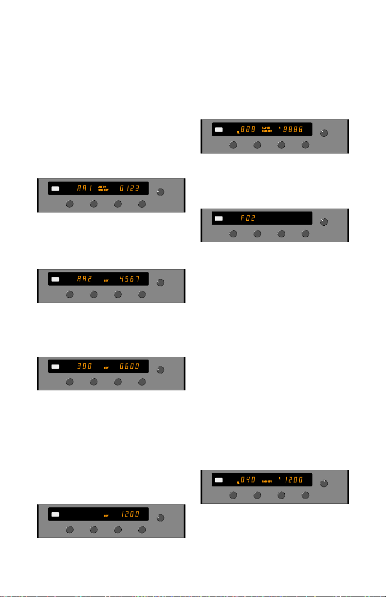
OFF- The unit is not energized. When the
unit is turned from “OFF” to some other
mode, the unit will display the installer-programmed aircraft address and maximum
airspeed according to the following
sequence: (Does not apply to the
ATCRBS-only Systems):
IDT
XPDR 1
R
GND
TST
ON
SBY
ALT
OFF
PUSH
VFR
a.) The “FL” window will display “ xe
“AA1”AA1” and the ident window will display the first 4 digits of the unique aircraft
address for 2 (two) seconds.
IDT
FL
XPDR 1
R
GND
TST
ON
SBY
ALT
OFF
PUSH
VFR
b.) The “FL” window will display “xe
“AA2”AA2” and the ident window will display the last 4 digits of the unique aircraft
address for 2 (two) seconds.
IDT
FL
XPDR 1
R
GND
TST
ON
SBY
ALT
OFF
PUSH
VFR
annunciated on the display in this mode.
The altitude display is disabled.
TST- (Test) The unit will illuminate all segments of the display for at least four seconds. A series of tests are performed internally that check the integrity of the Mode S
system.
GND
TST
IDT
XPDR 1
ON
SBY
ALT
OFF
PUSH
VFR
When a squitter error occurs, the
transponder is considered inoperative and
message will be reported on the altitude
display.
ALT ON
IDT
FL
XPDR 1
GND SBY
R
8888
GND
TST
ON
SBY
ALT
OFF
PUSH
VFR
Whenever an EEPROM error is detected,
the message “F02” signifying internal EEPROM failure, or “F03” signifying external
EEPROM failure, is reported in the altitude
side of the display.
When the unit detects a hardware failure that prevents the unit from operating as
a transponder, “F04” is displayed in the altitude window.
If the unit displays any of these failure
messages, it should be taken in for service.
If the unit has no errors, it remains in
the test mode.
All replies are disabled during TEST.
c.) The “FL” window will display the lower
limit and the ident window shall display the
upper limit of the preprogrammed maximum airspeed range for 2 (two) seconds.
The airspeed range displayed is one of the
following six: 0-75, 75-150, 150-300, 300600, 600-1200, and greater than 1200.
SBY- The unit is energized, but is inhibited
from replying to any interrogation. “SBY” is
IDT
300
FL
XPDR 1
R
GND
TST
ON
SBY
ALT
OFF
PUSH
VFR
GND- (Ground) The unit inhibits ATCRBS
Mode A & C interrogations but will reply to
all valid Mode S interrogations. The ID
4096 code is displayed on the right side of
the display and the altitude on the left.
“GND” is annunciated on the display in this
mode.
IDT
XPDR 1
TST
SBY
OFF
Note: An optional remote “air/ground”
switch may be installed on a landing gear
strut that will keep the Mode S unit in the
GND mode until airborne. The unit can
13
GND
ON
ALT
PUSH
VFR
Page 15

then be selected to “ON” or “ALT” on the
ground, but will continue to annunciate
“GND” and only accept Mode S interrogations. Once the aircraft is airborne and the
strut switch relaxes, the unit automatically
annunciates the selected mode and operates accordingly. This feature eliminates
the possibility of taking off and forgetting to
activate the Mode A/C capability of the
transponder.
ON- The unit is able to reply to all valid
Mode A, Mode C and Mode S interrogations, however; the altitude information of
Mode C reply and the altitude fields of the
Mode S replies are suppressed. The altitude display is blank and the ID 4096 code
is displayed on the right. “ON” is annunciated on the display in this mode.
GND
TST
IDT
300
FL
XPDR 1
ON
SBY
ALT
OFF
PUSH
VFR
ALT- The unit is able to reply to all valid
Mode A, Mode C and Mode S interrogations. The altitude information will be sent
in Mode C and the altitude field of Mode S
replies. The ID 4096 code will be display
on the right and the altitude will be displayed on the left (in hundreds of feet).
GND
TST
IDT
XPDR 1
ON
SBY
ALT
OFF
PUSH
VFR
XPDR 1 / XPDR 2 SWITCH
Since only one transponder can be active
at a time, the XPDR 1/2 switch is used to
select which transponder is active. In addition to providing quick access to a backup
system, the XPDR 1/2 switch can also act
GND
TST
ON
SBY
ALT
OFF
PUSH
VFR
GND
TST
ON
SBY
ALT
OFF
PUSH
VFR
071
ON
GND
SBY
ON
ALT
R
GND
IDT
XPDR 1
IDT
FL
XPDR 2
as a virtual “flip-flop” similar to that on the
COMM, NAV and ADF.
With XPDR 2 set for the VFR code,
ALT R
011
FL
ON
GND
ON
GND
IDT
XPDR 1
IDT
XPDR 2
GND
TST
ON
SBY
ALT
OFF
PUSH
VFR
GND
TST
ON
SBY
ALT
OFF
PUSH
VFR
and XPDR 1 set to the last ATC-assigned
squawk code, toggling the XPDR 1/2 switch
automatically activates the selected transponder while simultaneously putting the other
transponder in standby (even when the function switch is selected to an active mode).
DISPLAY ADJUST MODE
The display has 3 programmable adjustments. The first (dA 1) is for the response
time for dimming, the second (dA 2) is to set
the display for minimum brightness, and the
third (dA 3) is to compensate brightness for
different vendors and/or aging of the display.
To enter the Display Adjust Mode, perform the following steps:
1. Turn the function selector knob to TST.
2. Press and hold the “IDT” button for five
seconds until “dA1” appears in the altitude
window.
ALT ON
IDT
FL
XPDR 1
GND SBY
R
1200
GND
TST
ON
SBY
ALT
OFF
PUSH
VFR
3. Select the desired display adjustment by
depressing the “VFR” pushbutton.
(Select dA1, dA2, or dA3).
4. Set the proper adjustment value in the
IDENT window with the far right Ident
Code Selector Knob.
MODE RANGE DESCRIPTION
dA1 1 to 8 Photocell response
(1=fast, 8=slow).
(Normal= 1)
dA2 0 to 64 Display brightness
(0=dim, 64=bright)
(Normal= 20)
dA3 0 to 255 Vendor/Age comp.
(0=dim, 255=bright)
(Normal= 0)
5. Press the “IDT” pushbutton or turn the
Function Selector knob to exit the display
adjust mode and save the new values.
14
Page 16

Notes
15
Page 17

Honeywell International Inc.
Business, Regional & General Aviation
23500 W. 105th Street
Olathe, Kansas 66061
913-712-0400
Fax 913-712-1302
© 1999-2001 Honeywell International Inc.
006-08480-0002
Rev 2 8/2001
Printed in U.S.A.
N
 Loading...