

Page 1
Pilot’s Guide
Collision Avoidance System
CAS 66A
B TCAS I
Effective Date: 2/06 006-08746-0000 REV. 7
Page 2

The information contained in this manual is for reference use only. If
any information contained herein conflicts with similar information
contained in the Airplane Flight Manual Supplement, the information in
the Airplane Flight Manual Supplement shall take precedence.
WARNING
The enclosed technical data is eligible for export under Licanse Designation NLR
and is to be used solely by the individual/organization to whom it is addressed.
Diversion contrary to U.S. law is prohibited.
COPYRIGHT NOTICE
Copyright ©1994-1999, 2004, 2006 Honeywell International Inc.
All rights reserved.
Reproduction of this publication or any portion thereof by any means without the
express written permission of Honeywell International Inc. is prohibited. For further
information contact Technical Publications; Honeywell; One Technology Center;
23500 West 105th Street; Olathe, Kansas 66061. Telephone: (913) 712-0400.
Page 3

Table of ContentsCAS 66A Pilot's Guide
SYSTEM COMPONENTS ................................................................1
Traffic Displays: ...........................................................................1
TCAS Controls .............................................................................1
INTRODUCTION ..............................................................................2
TCAS: ..........................................................................................3
SECTION I : THEORY OF OPERATION AND SYMBOLOGY .....5
TCAS OPERATION .....................................................................6
TCAS I Sensitivity Level .........................................................6
TCAS I Surveillance Volumes ................................................8
Range Tracking Volumes ..................................................8
Altitude Tracking Volumes .................................................8
TCAS I Aural Inhibits ..............................................................8
TCAS TRAFFIC DISPLAY SYMBOLS ........................................9
Non-Threat Traffic ...................................................................9
Proximity Intruder Traffic .......................................................10
Traffic Advisory (TA) .............................................................10
Off Scale Traffic ....................................................................11
INDICATIONS AND VOICE ANNOUNCEMENTS .....................12
TCAS Traffic Advisory Annunciation .....................................12
SECTION I I: CONTROLS AND DISPLAYS .................................13
TCAS CONTROLS ....................................................................14
TCAS I Control Panel; CP 66A .............................................14
TCAS I Control Panel; CP 66B .............................................16
TRANSPONDER/TCAS CONTROLS ........................................18
KFS 578A Transponder/TCAS Control Unit .........................18
PS 578A Transponder/TCAS Control Unit ............................21
CD 671C Transponder/TCAS Control Unit ...........................24
PS 550 Transponder/TCAS Control Unit ..............................28
TRAFFIC DISPLAYS .................................................................32
TA/VSI & TID CONTROLS ........................................................33
Range Select ........................................................................33
BRT Control ..........................................................................33
TA SEL Mode .......................................................................33
Light Sensor ..........................................................................33
MODE & FAILURE ANNUNCIATIONS .....................................34
WEATHER RADAR INDICATORS ...........................................34
RDS 81, 82, 84 & 86, RDR 2000, RDR 2100
and Primus /Collins Color Indicators ...............................34
Weather Only Mode ..............................................................35
Weather with TCAS Traffic Mode .........................................35
TCAS Only Mode ..................................................................36
WX & TCAS MESSAGE FORMATS ..........................................36
TCAS Mode Annunciations ...................................................36
TCAS Fault Annunciations ....................................................37
TCAS ONLY mode ...............................................................37
i
Effective Date 6/04006-08746-0000 Rev 6
Page 4

Table of Contents
SECTION III: OPERATIONAL PROCEDURES ............................39
TCAS OPERATING PROCEDURES ........................................40
Before Takeoff .....................................................................40
Flight Procedures .................................................................40
After Landing ........................................................................41
Post Flight .......................................................................41
SECTION IV: SYSTEM CONSIDERATIONS ................................43
LIMITATIONS AND NOTES ......................................................44
Limitations .............................................................................44
Notes .....................................................................................44
APPENDIX: TCAS I SELF TEST ..................................................47
TCAS SELF TEST .....................................................................48
FAILURE CONDITIONS ............................................................49
CP 66A/B Control Panel Test ...............................................49
IVA 81A/C/D & TID 66A/D Optional Lamp Test ....................50
Radio Altimeter .....................................................................50
GLOSSARY OF TCAS TERMS .................................................50
Abbreviations and Definitions ...............................................50
Effective Date 2/06
ii
006-08746-0000 Rev 7
Page 5
System ComponentsCAS 66A Pilot's Guide
.5
ı
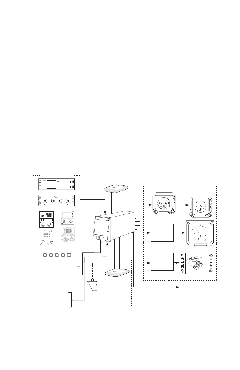
SYSTEM COMPONENTS
TRAFFIC DISPLAYS:
IVA 81A/C/D & TID 66A/D,
Compatible Radar Indicators via GC 362A,
Compatible EFIS.
TCAS CONTROLS
CP 66A/B TCAS I Controller
CD 671C, KFS 578A, PS 578A & PS 550 TCAS/Transponder
Controllers
Discretes
TPU 66A & ANT 67A W/ OPTIONAL OMNI.
Control Options
ABOVE
SBY
SBY
FL T/Wx
TCAS
ON
SBY
OFF
R 1
IDT
T/Wx
1 2
RANGE
<
>
OFF
PWR
Use only one option
AIRCRAFT SYSTEMS
• Radio Altimeter
• Pitch, Roll & Heading
• Barometric Altitude
• Suppression
• Discretes
• Cockpit Speaker
• Headphones
NORM
ON
BELOW
Wx
T/Wx
TCAS
OR
40
20
15
10
TST
5
3
PUSH TO TST
OR
TPR/
IDT
TCAS
TA
VFR
ALT
PUSH
ON
FL
SBY
TST
OR
SBY
TCAS Discretes
RNG
RNG
B
FAIL
ABOVE
TCAS
WX
NORM
BELOW
T/WX
PUSH FOR FL
ı
R
2
2200
TA/RA 5
XPDR/TCAS
RANGE
^
^
PUSH
TST
A/B
TST
PWR
FL
I
< >
D
T
IDT
ALT VFR
TA
ON
SBY
FL
TST
1/2
FL
Top Directional
ANT 67A
D
W
F
ı
TPU 66A
TPU 66A
TCAS I
PROCESSOR
D
W
F
Bottom Directional
ANT 67A
OR
Bottom Omni-Directional
L-Band AntennaAURAL SYSTEM
CAS 66A TCAS I Block Diagram
1
Traffic Displays Options
3 ATI TA/VSI
2
1
RNG 5
4
TA
SEL
+03
+12
6
0
-12
+08
4
.5
1
2
BRT
EFS
SG
EFIS MFD Display
BRT
Wx
WxA
NAV
MAP
GND
MAP
WXA
GAIN
Audio to Speaker
or Audio Panel
GC 362A
TCAS
GRAPHIC
UNIT
Effective Date 2/06006-08746-0000 Rev 7
3 ATI Dedicated
Traffic Display
RNG 5
+03
E
6
3
03
09
U 2.0
60
40
20
Radar Display
UP
DN
5
NM
ABOVE
12
09
13
BENDIX
LOG
ON
TST
SBY
OFF
80
RNG
RNG
TRK
TRK
UP
0
DN
Page 6

Introduction
INTRODUCTION
TCAS (an acronym formed from the phrase Traffic Alert and Collision
Avoidance System) is an airborne system used for detecting and
tracking aircraft near your own aircraft. TCAS I includes a TCAS
processor, antennas, a traffic display and a means to control the system. The TCAS processor and antennas detect and track other aircraft by interrogating their transponders. Aircraft detected, tracked,
and displayed by TCAS are referred to as Intruders. TCAS analyzes
the transponder replies to determine range, bearing and relative altitude, if the Intruder is reporting altitude. Should the TCAS processor
determine that a possible collision hazard exists, it issues visual and
aural advisories to the crew. The visual advisory is shown by symbols
on the traffic display. Complementing the traffic display, TCAS provides appropriate synthesized voice announcements in the cockpit. A
complete list of traffic symbols and announcements is given in the
Theory of Operation and Symbology section of this Pilot’s Guide.
TCAS is unable to detect any Intruding aircraft without an operating transponder. TCAS can detect and track aircraft with
either an ATCRBS (operating in Mode A or C) or Mode S
transponders.
The traffic display shows the Intruding aircraft’s position. TCAS identifies the relative threat of each Intruder by using various symbols and
colors. The Intruder’s altitude, relative to your own aircraft’s altitude, is
annunciated if the Intruder is reporting altitude. A trend arrow is used
to indicate if the Intruder is climbing or descending more than 500 feet
per minute. TCAS traffic may be displayed on a weather radar indicator, on a dedicated TCAS display, on a TCAS compatible EFIS
Display Unit or a TA/VSI (combination traffic display and vertical
speed instrument).
TCAS modes and functions are controlled by switches located on a
TCAS control panel or in combination with various other controls. A
description of controls is given in the Controls and Displays section of
this Pilot’s Guide.
ATC procedures and the “see and avoid concept” will continue to be
the primary means of ensuring aircraft separation. However, if communication is lost with ATC, TCAS adds a significant backup for collision avoidance.
Effective Date 6/94 006-08746-0000 Rev 2
2
Page 7

IntroductionCAS 66A Pilot's Guide
TCAS:
• Is compatible with the ATC System
• Determines if a threat exists from ATCRBS or Mode S Transponder
equipped aircraft
• Provides display and audio announcement to the crew
- Position information displayed on a traffic display
- Synthesized voice
• Incorporates sensor inputs and sophisticated algorithms to minimize
nuisance visual and aural annunciations.
3
Effective Date 5/99006-08746-0000 Rev 5
Page 8

Theory of Operation and Symbology
TTHHIISS PPAAGGEE IINNTTEENNTTIIOONNAALLLLYY LLEEFFTT BBLLAANNKK
Effective Date 5/93
4
006-08746-0000 Rev 0
Page 9
Theory of Operation and SymbologyCAS 66A Pilot's Guide
SECTION I : THEORY OF OPERATION AND
SYMBOLOGY
RNG 10
+05
TA ONLY
SECTION I DESCRIBES TCAS I THEORY OF OPERATION AND
SYMBOLOGY.
5
Effective Date 5/93006-08746-0000 Rev 0
Page 10

Theory of Operation and Symbology
TCAS OPERATION
TCAS monitors the airspace surrounding your aircraft by interrogating
the transponder of the Intruding aircraft. The interrogation reply
enables TCAS to compute the following information about the
Intruder:
1. Range between your aircraft and the Intruder.
2. Relative bearing to the Intruder.
3. Altitude and vertical speed of the Intruder, if the Intruder is
reporting altitude.
4. Closing rate between the Intruder and your aircraft.
Using this data TCAS predicts the time to, and the separation at, the
Intruder’s Closest Point of Approach (CPA). Should TCAS predict that
certain safe boundaries may be violated, it will issue a Traffic Advisory
(TA) to alert the crew that closing traffic is nearby.
TCAS I SENSITIVITY LEVEL
TCAS I separates the surrounding airspace into two altitude layers. A
different sensitivity threshold level for issuing TAs (traffic advisories) is
applied to each altitude layer. Lower altitudes have less sensitive TA
threshold levels to prevent unnecessary advisories in the higher traffic
densities anticipated at lower flight levels, i.e., terminal areas.
TCAS I has two sensitivity levels (SL) which are described in Table 1,
TCAS Sensitivity Levels. SL A is invoked using the following order of
precedence: (1) when the TCAS aircraft is below 2,000 feet AGL (if
equipped with radio altimeter) OR (2) when the landing gear is
Extended (no radio altimeter installed). SL B occurs under all other
flight conditions. Table 2, Typical Traffic Advisory Conditions for
Sensitivity Levels describes what conditions will cause a TA to be
issued. If aircraft is not equipped with either a radio altimeter or
retractable landing gear, TCAS I will stay in SL B at all times.
Sensitivity
Level
SL A In sensitivity level A, TCAS I performs surveillance and tracking
functions and provides traffic advisories. The conditions for sensitivity level A are any one of the following:
(1) Own aircraft is in-flight and is below 2,000 feet AGL, if a
radio altimeter is installed.
(2) Own aircraft is in-flight and the Landing Gear is extended, if a
radio altimeter is NOT installed.
Effective Date 6/94 006-08746-0000 Rev 2
DESCRIPTION
6
Page 11

Theory of Operation and SymbologyCAS 66A Pilot's Guide
SL B In sensitivity level B, TCAS I performs surveillance and tracking
functions and provides traffic advisories. The conditions for sensitivity level B are based on own aircraft in-flight and:
(1) If radio altitude source is installed and own aircraft altitude is
above 2,000 feet AGL (radio altitude).
(2) If radio altitude source is NOT installed and own aircraft has
Landing Gear Retracted.
(3) If the aircraft has a fixed landing gear and no radio altimeter is
installed.
Table 1: TCAS Sensitivity Levels
Sensitivity
Level
SL A The following conditions cause TCAS I to generate a TA in sensi-
CONDITIONS FOR TRAFFIC ADVISORIES (TAs)
tivity level A:
• TCAS calculates that if current closing rate is maintained, separation of less than 600 feet in altitude between own and
Intruder will occur in 20 seconds.
• Separation between own and Intruder is less than 1200 feet in
altitude and less than 0.20 nautical mile range.
• NAR (Non-Altitude Reporting) Intruder is within 15 seconds or
0.20 nautical mile range.
SL B The following conditions cause TCAS I to generate a TA in sensi-
Standby
or Fail • TAs are not generated.
Mode
tivity level B:
• TCAS I calculates that if current closing rate is maintained, sep-
aration of less than 800 feet in altitude between own and
Intruder will occur in 30 seconds.
• Separation between own and Intruder is less than 800 feet in
altitude and less than 0.55 nautical miles in range.
• NAR (Non-Altitude Reporting) Intruder is within 20 seconds or
0.55 nautical mile range.
Table 2: Typical Traffic Advisory Conditions for Sensitivity Levels
7
Effective Date 6/94006-08746-0000 Rev 2
Page 12

Theory of Operation and Symbology
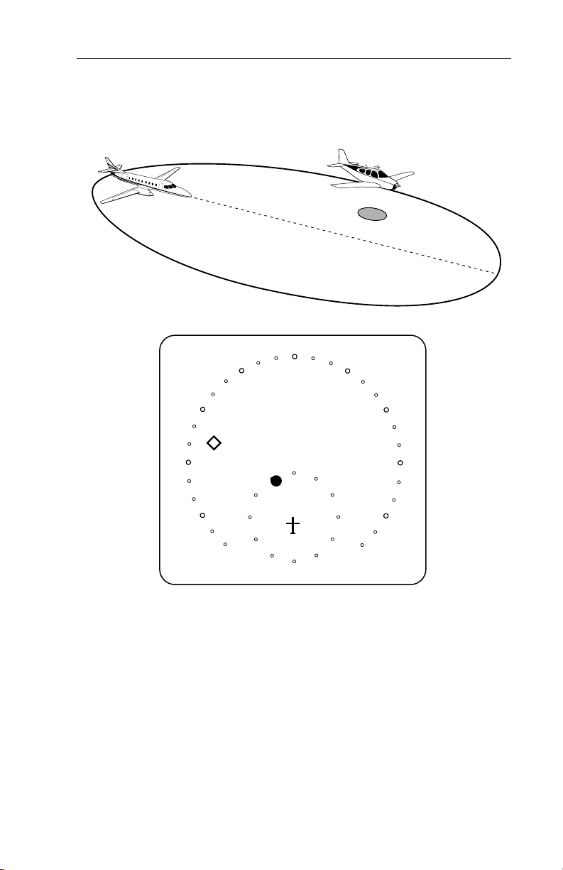
TCAS I SURVEILLANCE VOLUMES
Surveillance volume is that volume of airspace within which other aircraft with Mode S or ATCRBS transponders are tracked by own aircraft’s TCAS.
(1) Range Tracking Volumes
The shape and size of the range tracking volume is dependent on
whether Mode S or ATCRBS transponders are being interrogated,
whether tracking is occurring on a directional or OMNI antenna, and
attenuation levels applied to the transmitted pulses from the TCAS
processor’s transmitter. The typical range tracking volume is pictured
as an ellipse. The distance behind own-aircraft is about one half of
the forward distance. The tracking range to either side of own-aircraft
is about two thirds of the maximum forward distance.
The maximum forward range for TCAS is 40 nm. TCAS reduces
range tracking volumes in high density areas to reduce the number of
receptions to be processed by TCAS and for interference limiting.
TCAS can track as many as 45 aircraft and displays up to 30 of them.
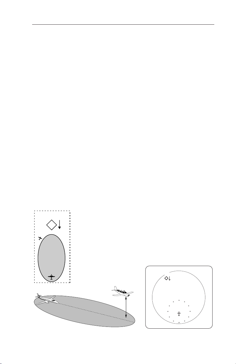
(2) Altitude Tracking Volumes
TCAS I tracks other transponder equipped aircraft that are within a relative altitude of +/-9,000 feet.
TCAS I AURAL INHIBITS
TCAS I will inhibit the aural annunciation using the following order of
precedence: (1) below 400 feet AGL (if equipped with radio altimeter)
OR (2) when the landing gear is Extended (no radio altimeter
installed). For installations aboard aircraft with fixed landing gear, the
aural annunciation is never inhibited by the TCAS I processor. The
aural annunciation is enabled above 600 feet AGL in aircraft equipped
with a radio altimeter.
Effective Date 5/93 006-08746-0000 Rev 0
8
Page 13
Theory of Operation and SymbologyCAS 66A Pilot's Guide
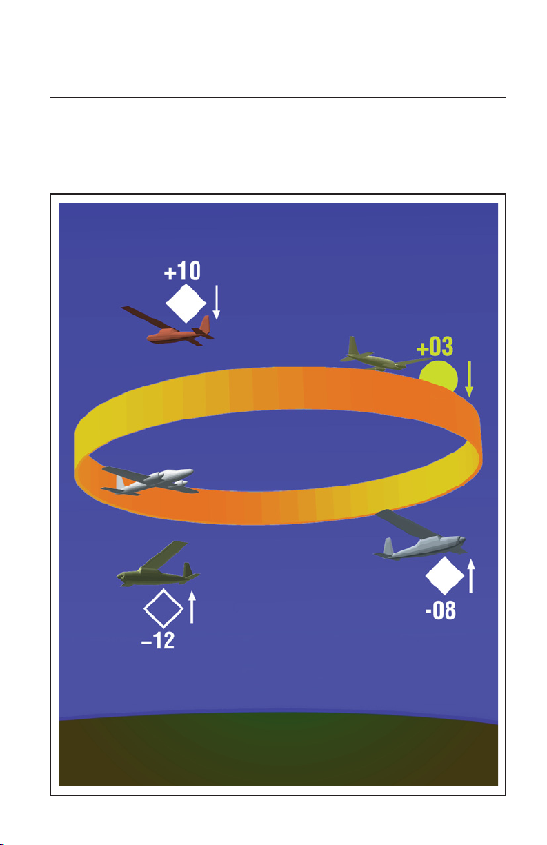
TCAS TRAFFIC DISPLAY SYMBOLS
TCAS I will display three different traffic symbols on the traffic display.
The type of symbol selected by TCAS is based on the Intruder’s location and closing rate. Relative bearing and distance to the Intruder are
shown by the position of the Intruder symbol in relation to the own-aircraft symbol.
The symbols change shape and color as separation decreases
between your aircraft and Intruders to represent increasing levels of
urgency.
The traffic symbols may also have an associated altitude tag that
shows relative altitude in hundreds of feet, indicating whether the
Intruder is climbing, flying level or descending. A + sign and number
above the symbol means the Intruder is above your altitude. A - sign
and number beneath indicates the Intruder is below your altitude. A
trend arrow appears when the Intruder’s vertical rate is 500 feet per
minute or greater.
No altitude number or trend arrow will appear beside any Intruder that
is Non-Altitude Reporting (NAR).
If TCAS direction finding techniques fail to locate the azimuth of another aircraft, a NO BEARING message appears on the screen when the
Intruder becomes a threat.
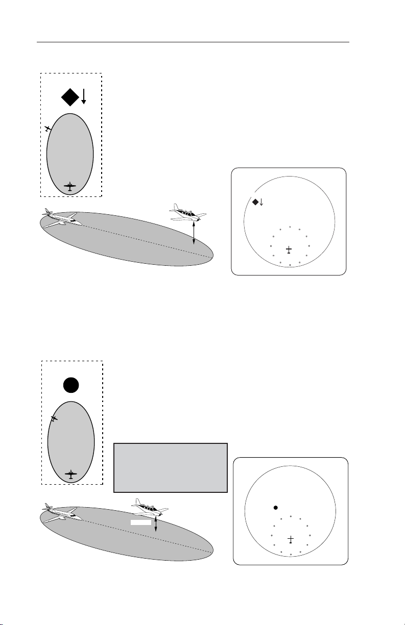
NON-THREAT TRAFFIC
+17
An open white diamond indicates that an Intruder’s
relative altitude is greater than ±1200 feet, or its distance is beyond 5 nm range. It is not yet considered
a threat.
This traffic is 1700 feet above your own altitude,
descending at 500 feet per minute or greater.
+1700 Ft. and
Descending
9
+17
RNG 5
Effective Date 5/93006-08746-0000 Rev 0
Page 14
Theory of Operation and Symbology
PROXIMITY INTRUDER TRAFFIC
+10
A filled white diamond indicates that the Intruding aircraft is within ±1200 feet and within 5 nm range, but
is still not considered a threat.
This Intruder is now 1000 feet above your aircraft and
descending.
RNG 3
+10
+1000 Ft. and
Descending
TRAFFIC ADVISORY (TA)
A symbol change to a filled yellow circle indicates that the Intruding
aircraft is considered to be potentially hazardous. Depending upon
TCAS sensitivity level, TCAS I will display a TA when time to CPA
(Closest Point of Approach) is 15 to 30 seconds.
Here the Intruder is 500 feet above your aircraft. A
+05
voice is heard in the cockpit, advising:
“Traffic, Traffic”
The crew should attempt to gain visual contact with
the Intruder and be prepared to maneuver upon visual acquisition.
The crew should take
no evasive action
based solely on the
TCAS display.
+05
+500 Ft.
Effective Date 6/94 006-08746-0000 Rev 2
10
RNG 3
Page 15
Theory of Operation and SymbologyCAS 66A Pilot's Guide
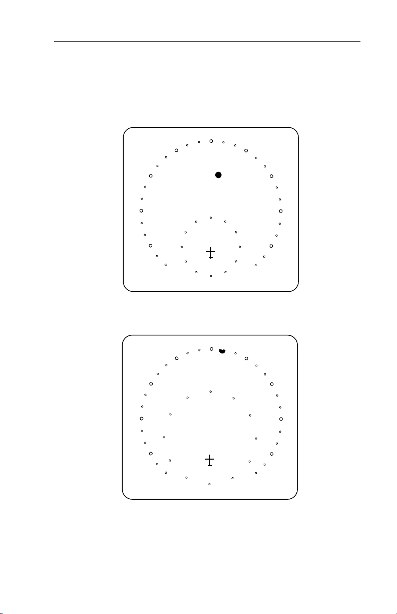
OFF SCALE TRAFFIC
Threat aircraft (TA’s) that are beyond the selected display range are
indicated by one half of the traffic symbol at the edge of the screen.
The position of the half-symbol represents the bearing of the Intruder.
RNG 5
-05
TA ONLY
TA traffic on 5 mile range.
RNG 3
-05
TA ONLY
Same TA traffic; beyond selected range.
11
Effective Date 6/94006-08746-0000 Rev 2
Page 16
Theory of Operation and Symbology
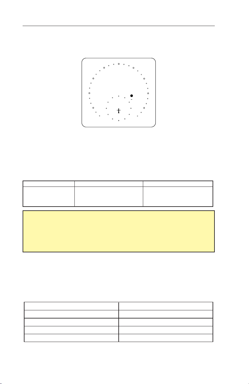
INDICATIONS AND VOICE ANNOUNCEMENTS
“Traffic, Traffic”
RNG 5
-04
TA ONLY
Situation:
One Intruder is ahead near the 2:00 o’clock position, between 2 and 3
miles, 400 feet below your altitude and closing. TCAS recognizes the
threat and issues a TA.
TCAS TRAFFIC ADVISORY ANNUNCIATION (TA):
Aural Visual Crew Response
“TRAFFIC, TRAFFIC”
A filled yellow circle on the
Traffic Display
Conduct visual search for the
Intruder. If successful, maintain
visual acquisition to ensure
safe operation.
IMPORTANT:
The pilot should NOT initiate evasive maneuvers using information
on the Traffic Display only. Use the TA (Traffic Advisory) symbol to
visually acquire the Intruder and be prepared to maneuver upon
visual acquisition.
Audio Announcements:
Synthesized voice announcements are issued by TCAS over the aircraft audio system. The following table lists all the audio messages,
and advisories, in the TCAS I vocabulary.
Audio Messages
CONDITION ADVISORY MESSAGE
Traffic Advisory “TRAFFIC, TRAFFIC”
If Previous TA is Active “TRAFFIC”
Self Test Passed “TCAS SYSTEM TEST OK”
Self Test Failed “TCAS SYSTEM TEST FAIL”
Effective Date 8/98
12
006-08746-0000 Rev 4
Page 17
Controls and DisplaysCAS 66A Pilot's Guide
SECTION II: CONTROLS AND DISPLAYS
ON
SBY
OFF
TCAS
TST
20
15
10
5
PUSH TO TST
3
FAIL
40
TCAS
WX
T/WX
PUSH FOR FL
SECTION II DESCRIBES CONTROLS AND
DISPLAYS OF THE TCAS I EQUIPMENT.
B
ABOVE
NORM
BELOW
FL
13
Effective Date 6/94006-08746-0000 Rev 2
Page 18
Controls and Displays
TCAS CONTROLS
This section describes the control units for the TCAS equipment.
Several types of control units are described. The TCAS functions can
be controlled by various control panels or discrete switches. Not all
the functions described are required in every installation.
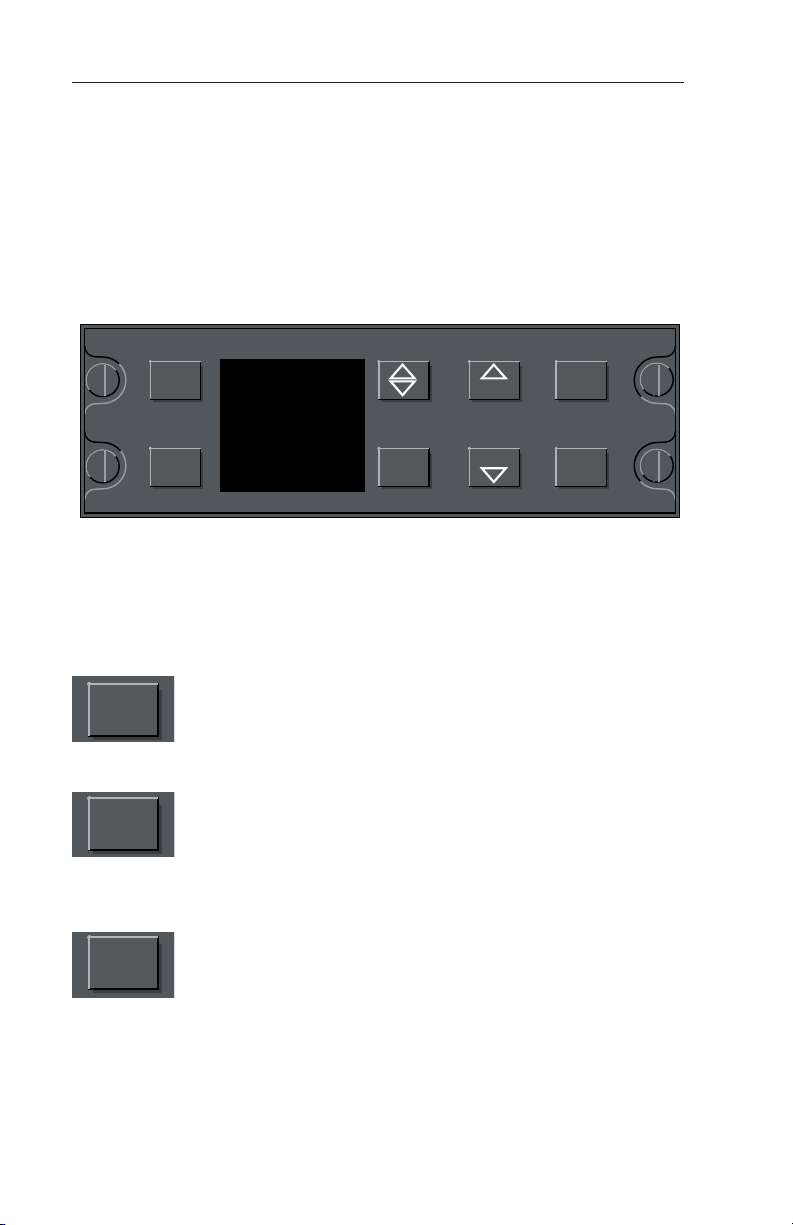
TCAS I CONTROL PANEL; CP 66A
SBY
FL T/Wx
SBY
ON
ABOVE
NORM
BELOW
Wx
T/Wx
TCAS
RNG
RNG
TST
PWR
CP 66A
TCAS I Control Panel
Note: The controls vary depending on CP 66A/CP 66B configuration
installed. All functions are the same as typical of units shown.
Pushing the PWR push button cycles the TCAS ON or
OFF. At power down, the control panel senses
PWR
whether the TCAS is in SBY or On mode. Upon powerup, the control returns the TCAS to the same condition.
Whenever TCAS is On, pressing SBY places the TCAS
in SBY (Standby) mode. In Standby mode, all TCAS
SBY
broadcast, surveillance, and tracking operations are
disabled and the traffic display is blanked except for a
“TCAS STBY” mode annunciation. If TCAS is in
Standby, pressing the SBY button places TCAS I in the
ON mode.
Pushing the TEST button initiates a comprehensive self
TST
test lasting approximately eight seconds. Refer to the
Appendix for a description of the self test function.
Effective Date 6/94 006-08746-0000 Rev 2
14
Page 19
Controls and DisplaysCAS 66A Pilot's Guide
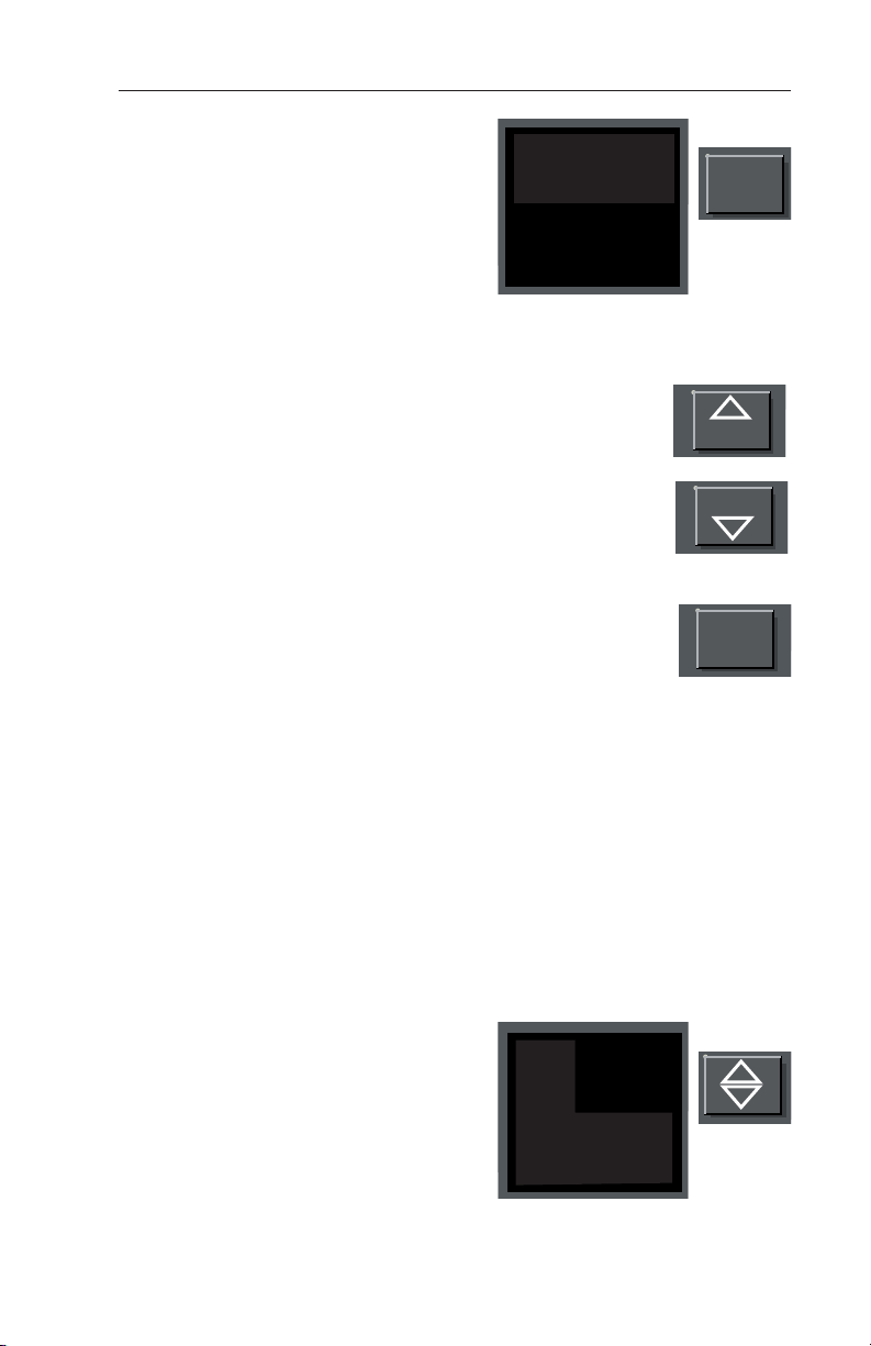
The T/Wx (TCAS/Weather) mode button is necessary in installations using
the weather radar indicator as the
traffic display. In these installations,
the T/Wx switch is used to select
between Weather Only, Weather with
TCAS Traffic and Traffic Only modes.
Details of the various modes are described later in this section under
Weather Radar Indicators.
TCAS RNG (Range) buttons are used to select the
range on the traffic display. The range selections are
3, 5, 10, 15, 20, and 40. All ranges are in nautical
miles.
SBY
ON
Note: This feature may not be available in all installations or this feature may be superseded by a range
ABOVE
NORM
BELOW
Wx
T/Wx
TCAS
T/Wx
RNG
RNG
control on the traffic display bezel.
The FL (Flight Level) push button replaces Intruder’s
relative altitude with absolute altitude for 15 seconds.
During this period the altitude is displayed in flight level
format. That is, 19,000 ft. is displayed as 190. After 15
seconds the absolute reading reverts to relative altitude.
The FL function is flagged below 18,000 feet MSL on most traffic displays unless barometric corrected altitude is available from an air data
source. FL is inhibited on the IVA 81A/C/D and the TID 66A/D units,
but not on the Radar indicator when used with GC 362A.
FL
If FL is selected while inhibited, “FL - - -” will show in place of own
flight level.
The A/B (Above/Below) push button selects altitude display limits.
The Above/Below selection has no effect on the TCAS logic giving
TAs. There are three choices available.
ABOVE Traffic that is between 8700 feet above and 2700 feet below
own aircraft will be displayed.
Typically ABOVE is used during the
climb phase of flight.
NORMAL Traffic that is between
2700 feet above and 2700 feet below
will be displayed. Typically NORMAL
is used during the en route phase of
flight.
15
SBY
ON
ABOVE
NORM
BELOW
Wx
T/Wx
TCAS
Effective Date 2/06006-08746-0000 Rev 7
Page 20

Controls and Displays
BELOW Traffic that is between 2700 feet above and 8700 feet below
will be displayed. Typically BELOW is used during the descent phase
of flight.
TCAS I CONTROL PANEL; CP 66B
B
ABOVE
NORM
BELOW
FL
ON
SBY
OFF
TCAS
TST
20
15
10
5
3
PUSH TO TST
FAIL
40
TCAS
WX
T/WX
PUSH FOR FL
CP 66B
TCAS I Control Panel
The CP 66B can have up to four separate knobs as shown above.
Depending upon the system interface, the Range Knob and/or Display
Selector may be removed.
The CP 66B amber Fail Annunciator will light during self test and in
normal operation will flash if a system failure has been detected. If a
failure has been detected, turning the Power Switch to OFF will turn
off the flashing annunciator.
Power Switch:
The OFF position deactivates selector switches and
ON
SBY
OFF
TST
push buttons and extinguishes FAIL annunciation if
on.
The SBY position places the TCAS in Standby mode.
In Standby mode, all TCAS broadcast, surveillance,
and tracking operations are disabled and the traffic display is blanked
except for a “TCAS STBY” mode annunciation.
The ON position enables the TCAS broadcast, tracking and surveillance operations at the selected range, display and altitude limit.
Pressing the TEST button in the center of the knob initiates a comprehensive self test lasting approximately eight seconds. Refer to the
Appendix for a description of the self test function.
Effective Date 8/98 006-08746-0000 Rev 4
16
Page 21

Controls and DisplaysCAS 66A Pilot's Guide
TCAS Range Knob:
15
10
WX
40
20
5
3
FL
The TCAS RANGE knob is used to select the range
on the traffic display. The range selections are 3, 5,
10, 15, 20, and 40. All ranges are in nautical miles.
Note: This feature may not be available in all installations or this feature may be superseded by a range
control on the traffic display bezel.
Display Select Switch:
The Display Select Switch is used in installations
where the weather radar indicator is the traffic display. It selects between T/Wx (TCAS w/Weather),
Wx (Weather Only), and TCAS (Traffic Only) presentations on the radar screen. Details of the various modes are
described later in this section under Weather Radar Indicators.
Altitude Limit Switch:
The Altitude Limit Select Switch selects altitude display limits. It has no effect on the TCAS logic giving
TAs. There are three selections available.
ABOVE - Traffic that is between 8700 feet above and 2700 feet below
own aircraft will be displayed. Typically ABOVE is used during the
climb phase of flight.
TCAS
T/WX
ABOVE
NORM
BELOW
NORMAL - Traffic that is between 2700 feet above and 2700 feet
below will be displayed. Typically NORMAL is used during the en
route phase of flight.
BELOW - Traffic that is between 2700 feet above and 8700 feet below
will be displayed. Typically BELOW is used during the descent phase
of flight.
The FL (Flight Level) push button in the center of the Altitude Limit
Select Switch replaces Intruder’s relative altitude with absolute altitude
for 15 seconds. During this period the altitude is displayed in flight
level format. That is, 19,000 ft. is displayed as 190. After 15 seconds
the absolute reading reverts to relative altitude.
The FL function is flagged below 18,000 feet MSL on most traffic displays unless barometric corrected altitude is available from an air data
source. FL is inhibited on the IVA 81A/C/D and the TID 66A/D units,
but not on the Radar indicator when used with GC 362A.
If FL is selected while inhibited, “FL - - -” will show in place of own
flight level.
17
Effective Date 2/06006-08746-0000 Rev 7
Page 22

Controls and Displays
TRANSPONDER/TCAS CONTROLS
KFS 578A TRANSPONDER/ TCAS CONTROL UNIT
TRANSPONDER 1-2
MODE S
FLIGHT LEVEL
TCAS MODE
TCAS RANGE
TRANSPONDER MODE
TCAS RANGE
ON/OFF SWITCH
PUSH-TCAS
ABOVE/NORM/BELOW
OFF
KFS 578A Single or Dual Mode S/TCAS Control Unit (Dual Unit shown)
KFS 578A CONTROLS AND DISPLAYS
The KFS 578A Control Unit is the master control for both the TCAS system and transponder. The KFS 578A will also display the selected 4096
ATC code and current mode of operation in the display window. Versions
are available to control one or two transponders. A “Fail” annunciation
indicates failure of the selected transponder, antenna or control data.
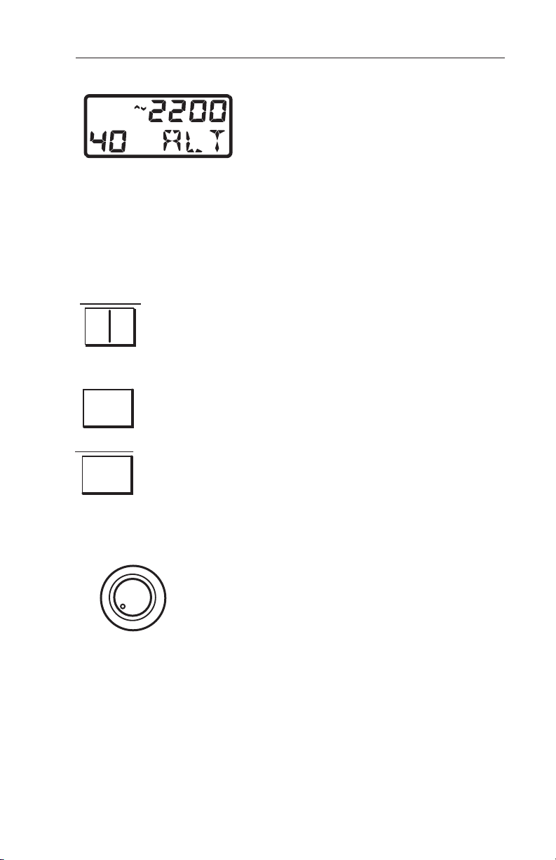
4096 CODE AND FLIGHT LEVEL TEST INDICATOR
B
2
FL
2200
TA 5
ALT
XPDR/TCAS
RANGE
SBY
^
^
PUSH
1/2
TRANSPONDER 1-2
SELECT
< >
IDT
ALT VFR
ON
PUSH
TST
FL
I
D
T
TA
FUNCTION
SELECT
PHOTOCELL
TCAS
ABOVE/NORM/BELOW
IDENT BUTTON
IDENT
4096 SQUAWK CODE SELECT
PUSH-ADVANCE CURSOR
FL-PUSH AND HOLD-MOMENTARY
CHANGE TCAS RELATIVE ALTITUDE
Note: If the KFS 578A is interfaced to a MST 67A Mode S transponder
and the MST 67A senses a failure, a failure annunciation will be shown.
A maintenance check should be performed.
The Display Window Displays ATC code
2
FL
2200
TA 5
1/2
IDTALT
selection, whether transponder #1 or #2 is
active, transponder mode, transponder ident,
< >
own aircraft flight level (in TEST), TCAS mode,
TCAS range and TCAS above, below or normal
vertical display limit selected.
1/2 selects the active transponder. The other
unit is placed in standby.
(Pushbutton)
I
D
T
IDT initiates IDENT feature for ATC.
(Pushbutton)
Effective Date 6/04 006-08746-0000 Rev 6
18
Page 23

Controls and DisplaysCAS 66A Pilot's Guide
RANGE
OFF
PUSH
The outer knob on the left hand dual concentric switch
selects the Traffic Advisory display range in nautical
miles. The selected range is annunciated on the traffic
display. The range annunciation is the maximum displayed range to the front of the aircraft. The selected
^
range has no effect on the TCAS logic giving TAs.
^
Note: Selected range is displayed in the upper right hand corner of a
TA/VSI.
The inner concentric knob on the left may include an on/off switch (clockwise = on) and when pushed selects Traffic Advisory altitude display limits (Above, Normal or Below). The Above/Below select knob has no
effect on the TCAS logic giving TAs.
ABOVE 8700 feet above; 2700 feet below. Typically used during climb
phase of flight.
NORMAL 2700 feet above; 2700 feet below. Typically used during en
route phase of flight.
BELOW 2700 feet above; 8700 feet below. Typically used during
descent phase of flight.
Note: All knobs are continuous rotatory and do not roll over or stop.
KFS 578A FUNCTION SELECTOR, ATC CODE SELECT & MOMENTARY TCAS DISPLAY FLIGHT LEVEL SELECT
The outer concentric knob on the right selects the Mode S and TCAS
mode of operation.
Rotating the function knob (CCW) to the TST position
ALT VFR
ON
SBY
TST
PUSH
FL
initiates a comprehensive self test lasting approxi-
TA
mately eight seconds. All segments of the display
are illuminated for 2 seconds, then the code window
will display the encoded altitude for four seconds,
then the control unit will return to the previously
selected mode. (Refer to the Test section in the
Appendix for a detailed description of test functions.)
19
Effective Date 6/04006-08746-0000 Rev 6
Page 24

Controls and Displays
SBY places the Mode S Transponder and TCAS in standby. SBY is
annunciated on the display window. Use SBY during ground operations.
ON activates the selected transponder without altitude reporting. TCAS
is in standby. ON is annunciated in the display window.
ALT activates Mode S transponder with altitude reporting, TCAS system
in standby.
Selecting VFR for more than 3 seconds changes the ATC code to the
pre-programmed VFR code (Typically 1200). VFR is annunciated in the
display window for the 3 seconds prior to switching the programmed
code The control unit will return to the mode selected prior to making the
VFR selection.
The VFR code can be programmed to be any code by the following technique:
a. Place the function selector to VFR.
b. Select the VFR code as required.
c. Push the Ident (IDT) button, or wait 3 seconds, or rotate the Function
switch to the desired mode.
The TA (Traffic Advisory) mode. Activates the Mode S transponder, altitude reporting and TCAS “TA ONLY” mode. Traffic will be presented on
the traffic (TA) display.. “TA” mode is annunciated in the control unit display window and “TA ONLY” will be annunciated on the TCAS traffic display(s).
The traffic display switches to the FL (flight level) display function when
the inner knob is pressed in for more than four seconds. The relative altitude tags are replaced with absolute altitude (FL) tags. The traffic display
will revert to relative altitude after 15 seconds.
The FL feature is usually flagged below 18,000 feet MSL unless barometric corrected altitude is available from an air data source. FL is
flagged on the IVA 81A but not on the radar indicator when used with
the GC 362A, traffic displays. If FL is selected while flagged, "FL---" is
annunciated instead of own flight level.
Effective Date 6/04 006-08746-0000 Rev 6
20
Page 25

Controls and DisplaysCAS 66A Pilot's Guide
PS 578A TRANSPONDER/TCAS CONTROL UNIT
PS 578A Single or Dual Mode S/TCAS Control Unit (Dual Unit shown)
PS 578A CONTROLS AND DISPLAYS
The PS 578A Control Unit is the master control for both the TCAS system and transponder. The PS 578A will also display the selected 4096
ATC code and current mode of operation in the display window. Versions
are available to control one or two transponders. A “Fail” annunciation
indicates failure of the selected transponder, antenna or control data.
Note: If the PS 578A is interfaced to a MST 67A Mode S transponder
and the MST 67A senses a failure, a failure annunciation will be shown.
A maintenance check should be performed.
The Display Window Displays ATC code
selection, Flight ID (FID) selection, whether
transponder #1 or #2 is active, transponder
mode, transponder ident, own aircraft flight
level (in TEST), TCAS mode, TCAS range
and TCAS above, below or normal vertical
display limit selected.
21
Effective Date 6/04006-08746-0000 Rev 6
Page 26

Controls and Displays
1/2 selects the active transponder. The other unit is
placed in standby.
(Pushbutton)
IDT initiates IDENT feature for ATC.
(Pushbutton)
FID allows entry of an alphanumeric flight identification.
Selecting the right inner pushbutton will cycle through
the eight characters to be changed. Rotating the right
inner knob will change the contents of the selected
(flashing) character.
The outer knob on the left hand dual concentric switch
selects the Traffic Advisory display range in nautical
miles. The selected range is annunciated on the traffic
display. The range annunciation is the maximum displayed range to the front of the aircraft. The selected
range has no effect on the TCAS logic giving TAs.
Note: Selected range is displayed in the upper right hand corner of a
TA/VSI.
The inner concentric knob on the left includes an on/off switch (push
on/off) and when rotated selects Traffic Advisory altitude display limits
(Above, Normal or Below). The Above/Normal/Below select knob has no
effect on the TCAS logic giving TAs.
ABOVE 8700 feet above; 2700 feet below. Typically used during climb
phase of flight.
NORMAL 2700 feet above; 2700 feet below. Typically used during en
route phase of flight.
BELOW 2700 feet above; 8700 feet below. Typically used during
descent phase of flight.
Note: All knobs are continuous rotary and do not roll over or stop.
Effective Date 6/04 006-08746-0000 Rev 6
22
Page 27

Controls and DisplaysCAS 66A Pilot's Guide
PS 578A FUNCTION SELECTOR, ATC CODE SELECT & MOMENTARY TCAS DISPLAY FLIGHT LEVEL SELECT
The outer concentric knob on the right selects the Mode
S and TCAS mode of operation.
Rotating the function knob (CCW) to the TST position
initiates a comprehensive self test lasting approximately
eight seconds. All segments of the display are illuminated for 2 seconds, then the code window will display the encoded altitude
for four seconds, then the control unit will return to the previously selected mode. (Refer to the Test section in the Appendix for a detailed
description of test functions.)
SBY places the Mode S Transponder and TCAS in standby. SBY is
annunciated on the display window. Use SBY during ground operations.
ON activates the selected transponder without altitude reporting. TCAS
is in standby. ON is annunciated in the display window.
ALT activates Mode S transponder with altitude reporting, TCAS system
in standby.
Selecting VFR for more than 3 seconds changes the ATC code to the
pre-programmed VFR code (Typically 1200). VFR is annunciated in the
display window for the 3 seconds prior to switching the programmed
code The control unit will return to the mode selected prior to making the
VFR selection.
The VFR code can be programmed to be any code by the following technique:
a. Place the function selector to VFR.
b. Select the VFR code as required.
c. Push the Ident (IDT) button, or wait 3 seconds, or rotate the Function
switch to the desired mode.
The TA (Traffic Advisory) mode. Activates the Mode S transponder, altitude reporting and TCAS “TA ONLY” mode. Traffic will be presented on
the traffic (TA) display. “TA” mode is annunciated in the control unit display window and “TA ONLY” will be annunciated on the TCAS traffic display(s).
23
Effective Date 6/04006-08746-0000 Rev 6
Page 28

Controls and Displays
< >
The traffic display switches to the FL (flight level) display function when
the inner knob is pressed in for more than four seconds. The relative altitude tags are replaced with absolute altitude (FL) tags. The traffic display
will revert to relative altitude after 15 seconds.
The FL feature is usually flagged below 18,000 feet MSL unless barometric corrected altitude is available from an air data source. FL is
flagged on the IVA 81A but not on the radar indicator when used with
the GC 362A, traffic displays. If FL is selected while flagged, "FL---" is
annunciated instead of own flight level.
CD 671C TRANSPONDER/ TCAS CONTROL UNIT
TCAS ABOVE/BELOW/NORMAL
TRANSPONDER 1-2
IDENT
RANGE
TRANSPONDER 1-2
SELECT
4096 SQUAWK CODE
SELECT
PUSH INNER KNOB FOR
ABOVE/BELOW/NORMAL
SELECT
1
IDT
1 2 IDTT/Wx
RANGE
OFF
4096 CODE &FLIGHT LEVEL TEST INDICATION
TPR/
TCAS
TA
VFR
ALT
PUSH
ON
FL
SBY
TST
TRANSPONDER MODE
TCAS / WEATHER MODE BUTTON
IDENT BUTTON
FL PUSH AND HOLDMOMENTARY CHANGE
TCAS RELATIVE ALTITUDE
FUNCTION SELECT
CD 671C Single or Dual Mode S/TCAS Control Unit (Dual Unit shown)
CD 671C CONTROLS AND DISPLAYS
The CD 671C Control Unit is the master control for both the TCAS
system and transponder. The CD 671C will also display the selected
4096 ATC code and current mode of operation in the display window.
Versions are available to control one or two transponders. A “Fail”
annunciation indicates failure of the selected transponder, antenna or
control data.
Note: If the CD 671A is interfaced to a MST 67A Mode S transponder
and the MST 67A senses a failure, a failure annunciation will be shown.
A maintenance check should be performed.
Effective Date 6/04 006-08746-0000 Rev 6
24
Page 29
Controls and DisplaysCAS 66A Pilot's Guide
< >
The Display Window displays the ATC
R1
IDT
All display annunciations are seen during the control unit self-test.
The "R" annunciation is only seen during self-test. "FL" on the control
unit is only displayed during self-test and indicates the transponder's
encoded altitude. Continuous FL mode is selected by activating Ext.
SBY discrete and turning mode knob to “TST”
The 1/2 push button selects No. 1 or No. 2 as the active
1 2
IDT
transponder. The other unit is placed in standby. The
Display Window shows which transponder is the active
source.
The IDT push button initiates the IDENT feature for ATC.
The IDENT function is used at the request of an Air Traffic
Controller, and holds the Ident reply for 18 ± 1 seconds.
code selection, whether transponder #1
or #2 is active, transponder mode,
transponder ident, own aircraft flight level
(in TEST), TCAS mode, TCAS range
and TCAS above, below or normal vertical display limit selected.
The T/Wx (TCAS/Weather) mode button is necessary in
T/Wx
OFF
installations using the weather radar indicator as the traffic
display. In these installation, the T/Wx switch is used to
select between Weather Only, Weather with TCAS Traffic
and Traffic Only modes.
RANGE
The outer knob selects the traffic display range in nm
(nautical miles). This knob can select 3, 5, 10, 15, 20
or 40 nm range on the TCAS traffic display. The
range is displayed in the display window during range
selection.
Note: The Range knob is continuous rotary and does not roll over or stop.
The traffic display may have another range select source. The selected TCAS range is always annunciated on the traffic display. The range
annunciated is the maximum displayed range to the front of the aircraft.
The range to the rear is 1/2 the annunciated range. The selected range
has no effect on the TCAS logic giving TAs.
25
Effective Date 6/04006-08746-0000 Rev 6
Page 30

Controls and Displays
The inner concentric knob may include an optional ON/OFF switch;
clockwise is ON. When the inner knob is pushed, the Traffic Advisory
altitude (Above/Norm/Below) display limits are sequentially selected.
There are three display levels to choose from.
ABOVE; 8700 feet above and 2700 feet below, is typically used during the climb phase of flight. A "^" (carat) will be annunciated in the
display window.
NORMAL; 2700 feet above and 2700 feet below, is used during the
enroute phase of flight. Both the "^" and "v" (carats) will be annunciated in the display window.
BELOW; 2700 feet above and 8700 feet below is used during the
descent phase of flight. A "v" (carat) will be annunciated in the display
window.
The Above/Below selection has no effect on the TCAS logic giving
TAs.
CD671A
FUNCTION SELECTOR, ATC CODE SELECT & MOMEN-
TARY TCAS DISPLAY FLIGHT LEVEL SELECT
The dual concentric knobs on the right side of the unit are used to
select the ATC code & TCAS/Transponder mode and the TCAS flight
level feature. The outer concentric knob selects the Mode S and
TCAS mode of operation. The mode is annunciated in the display
window.
TST Rotating the outer function knob (CCW) to
the TST position initiates a comprehensive self-test
lasting approximately eight seconds. All segments
of the display are illuminated for 2 seconds, then
the code window will display the encoded altitude
for four seconds, then the control unit will return to
the previously selected mode.
ALT
ON
SBY
TST
VFR
TA
PUSH
FL
SBY places the Mode S Transponder and TCAS in standby. SBY is
annunciated in the display window. Use standby during ground operations.
ON activates the selected transponder without altitude reporting.
TCAS is in standby. ON is annunciated in the display window.
Effective Date 6/04 006-08746-0000 Rev 6
26
Page 31

Controls and DisplaysCAS 66A Pilot's Guide
ALT Activates Mode S transponder with altitude reporting, TCAS system in standby.
VFR Selecting VFR for more than 3 seconds changes the ATC code
to the pre-programmed VFR code (typically 1200). VFR is annunciated in the display window for the 3 seconds before switching to the programmed code. The control unit will return to the mode selected prior
to making the VFR selection. The VFR code can be programmed to
any code by the following technique:
1. Place the function selector to VFR.
2. Select the VFR code as required.
3. Push the Ident (IDT) button, or wait 3 seconds, or rotate the
Function switch to the desired mode.
TA (TA Traffic Advisory) mode. TA activates the Mode S transponder, altitude reporting and TCAS "TA ONLY" mode. Traffic will be presented on the traffic (TA) display. "TA" mode is annunciated in the
control unit display window and "TA ONLY" will be annunciated on the
TCAS traffic display(s).
The inner concentric knob on the right selects the 4096 ATC code and
when pushed and held for more than four seconds switches the TCAS
traffic display to the FL (flight level) display function. To select an ATC
code, momentarily push this knob to start the left hand digit in the ATC
code flashing, twist the knob to change the number. Momentarily
push the knob again to move the flashing digit one space to the right
and twist the knob to change the digit. Repeat for the third and fourth
digit of the ATC code. The flashing digit will stop flashing 3 seconds
after the last change.
The traffic display switches to the FL (flight level) display function
when the inner knob is pressed in for more than four seconds. The
relative altitude tags are replaced with absolute altitude (FL) tags. The
traffic display will revert to relative altitude after 15 seconds.
The FL feature is usually flagged below 18,000 feet MSL unless barometric corrected altitude is available from an air data source. FL is
flagged on the IVA 81A but not on the radar indicator when used with
the GC 362A, traffic displays. If FL is selected while flagged, "FL---" is
annunciated instead of own flight level.
27
Effective Date 6/04006-08746-0000 Rev 6
Page 32

Controls and Displays
PS 550 TRANSPONDER/ TCAS CONTROL UNIT
PS 550 Single or Dual Mode S/TCAS Control Unit (Dual Unit shown)
PS 550 CONTROLS AND DISPLAYS
The PS 550 Control Unit is the master control for both the TCAS system and transponder. The PS 550 will also display the selected 4096
ATC code and current mode of operation in the display window.
Versions are available to control one or two transponders. A “Fail”
annunciation indicates failure of the selected transponder, antenna or
control data.
Note: If the PS 550 is interfaced to a MST 67A Mode S transponder and
the MST 67A senses a failure, a failure annunciation will be shown. A
maintenance check should be performed.
The Display Window displays the ATC
code selection, whether transponder #1
or #2 is active, transponder mode,
transponder ident, own aircraft flight level
(in TEST), TCAS mode, TCAS range and
TCAS above, below or normal vertical
display limit selected.
All display annunciations are seen during the control unit self-test.
Effective Date 6/04 006-08746-0000 Rev 6
28
Page 33

Controls and DisplaysCAS 66A Pilot's Guide
The 1/2 push button selects No. 1 or No. 2 as the active
transponder. The other unit is placed in standby. The
Display Window shows which transponder is the active
source.
The TST push button initiates a comprehensive self-test
lasting approximately eight seconds. All segments of the
display are illuminated for 2 seconds, then the code window will display the encoded altitude for four seconds.
The MODE push button sequentially selects the ATC,
TFC or FL mode, FID and ADC.
ATC Mode - Allows entry of the four digit ATC code.
Honeywell MST 67A configuration
knob selects each of the four positions for entry, and
the right inner knob selects the content.
Collins TDR-94D configuration:
enters the first two digits and the right inner knob
enters the last two digits.
The right outer knob
: The right outer
TFC Mode play operating mode (AUTO - data Pop-up or ON - full time display).
FL Mode absolute altitude for display. The relative altitude tags are replaced
with absolute altitude (FL) tags. The traffic display will revert to relative
altitude after 15 seconds
The FL feature is usually flagged below 18,000 feet MSL unless barometric corrected altitude is available from an air data source. FL is
flagged on the IVA 81A but not on the radar indicator when used with
the GC 362A, traffic displays. If FL is selected while flagged, "FL---" is
annunciated instead of own flight level.
FID Mode - Allows entry of the eight digit alphanumeric flight ID code.
The right outer knob selects each of the eight positions for entry, and
the right inner knob selects the alphanumeric character.
ADC Mode - Allows selection of the air data computer used by the
TCAS.
(Collins TDR-94D only)
Allows selection of the traffic dis-
(Honeywell MST-67A only)
29
Allows selection of relative or
Effective Date 6/04006-08746-0000 Rev 6
Page 34

Controls and Displays
The ID push button in the center of the Code Selector
knob initiates the IDENT feature for ATC. The IDENT
function is used at the request of an Air Traffic
Controller, and holds the Ident reply for 18 ± 1 seconds.
PS 550
ALTITUDE LIMITS SELECT
STBY places the Mode S Transponder and TCAS in standby. SBY
is annunciated in the display window. Use standby during ground
operations.
ALT OFF activates the selected transponder without altitude reporting. TCAS is in standby. ON is annunciated in the display window.
XPDR Activates Mode S transponder with altitude reporting, TCAS
system in standby.
TA (TA Traffic Advisory) mode. TA activates the Mode S transponder, altitude reporting and TCAS "TA ONLY" mode. Traffic will be presented on the traffic (TA) display. "TA" mode is annunciated in the
control unit display window and "TA ONLY" will be annunciated on the
TCAS traffic display(s).
FUNCTION SELECTOR, TCAS RANGE SELECT & TCAS
The dual concentric knobs on the left side of
the unit are used to select the
TCAS/Transponder mode, the TCAS range
and the TCAS altitude limits. The outer concentric knob selects the Mode S and TCAS
mode of operation. The mode is annunciated in the display window.
The inner knob selects the traffic display range in nm (nautical miles).
This knob can select 3, 5, 10, 15, 20 or 40 nm range on the TCAS
traffic display. The range is displayed in the display window during
range selection.
Note: The Range knob is continuous rotary and does not roll over or stop.
Effective Date 6/04 006-08746-0000 Rev 6
30
Page 35

Controls and DisplaysCAS 66A Pilot's Guide
The traffic display may have another range select source. The selected TCAS range is always annunciated on the traffic display. The range
annunciated is the maximum displayed range to the front of the aircraft.
The range to the rear is either full annunciated range or 1/2 the annunciated range, depending on the display. The selected range has no
effect on the TCAS logic giving TAs.
When the inner knob is pushed, the Traffic Advisory altitude
(Above/Norm/Below) display limits are sequentially selected. There
are three display levels to choose from.
ABOVE; 8700 feet above and 2700 feet below, is typically used during the climb phase of flight. A "^" (carat) will be annunciated in the
display window.
NORMAL; 2700 feet above and 2700 feet below, is used during the
enroute phase of flight. Both the "^" and "v" (carats) will be annunciated in the display window.
BELOW; 2700 feet above and 8700 feet below is used during the
descent phase of flight. A "v" (carat) will be annunciated in the display
window.
The Above/Below selection has no effect on the TCAS logic giving
TAs.
31
Effective Date 6/04006-08746-0000 Rev 6
Page 36

Controls and Displays
TRAFFIC DISPLAYS
TCAS traffic can be displayed on a
variety of instruments or indicators.
The following describes the various
TCAS traffic displays.
The (IVA 81A/C/D) TA/VSI displays
combine the vertical speed instrument with the Traffic display functions
on an LCD screen. A pointer indicates the aircraft’s VS (vertical
speed) against the scale around the
circumference of the circle. A VSI
IVA 81A/C/D TA/VSI Traffic
Advisory and Vertical
Speed Indicators
location is presented on the face of the display inside the vertical speed
scale.
Note: “RA FAIL” may annunciate during system start up prior to air
data coming on line or if air data fails. (“RA FAIL” is not a required flag
for TCAS I)
flag, which would be shown in the
lower right-hand corner, will cause
the VS pointer to disappear if a VS
source failure is detected. The traffic
The TID 66A/D is a dedicated TCAS
traffic display similar to the TA/VSI
without any vertical speed functions.
The bearing and distance of Intruder
aircraft are relative to the own-aircraft
symbol. The own-aircraft symbol is
located a third up from the bottom of
the screen.
The full scale display range directly
ahead of the aircraft is annunciated in
the upper right-hand corner. The distance aft is one-half the annunciated
TID 66A/D TCAS I
Traffic Display
circle indicated by blue dots every 30° is present at every range except
40 nm.
The lower right-hand corner of the TID 66A/D annunciates the
Above/Below and FL display formats. The FL feature is inhibited below
18,000 feet MSL unless barometric corrected altitude is available from
an air data source. If FL is selected while inhibited, “FL - - -” is annun-
Effective Date 2/06 006-08746-0000 Rev 7
range. The distance to the sides of
the aircraft (at 90° and 270°) is twothirds the annunciated range. A 2 nm
32
Page 37

Controls and DisplaysCAS 66A Pilot's Guide
ciated. When appropriate Flight Level data is available, current aircraft
Flight Level is displayed.
The lower left-hand corner annunciates the TCAS mode and TCAS
flag condition. See the list of Mode & Failure Annunciations below.
Two blocks are reserved in the lower center of the screen to display No
Bearing TA traffic. Occasionally TCAS can compute range and range
closure but not relative bearing to Intruder aircraft. “No Bearing” traffic
will be depicted as text and not a traffic symbol. A message such as
“2.0NM/-020” in yellow is a No Bearing TA for an Intruder 2.0 nm away
200 Ft. above and descending.
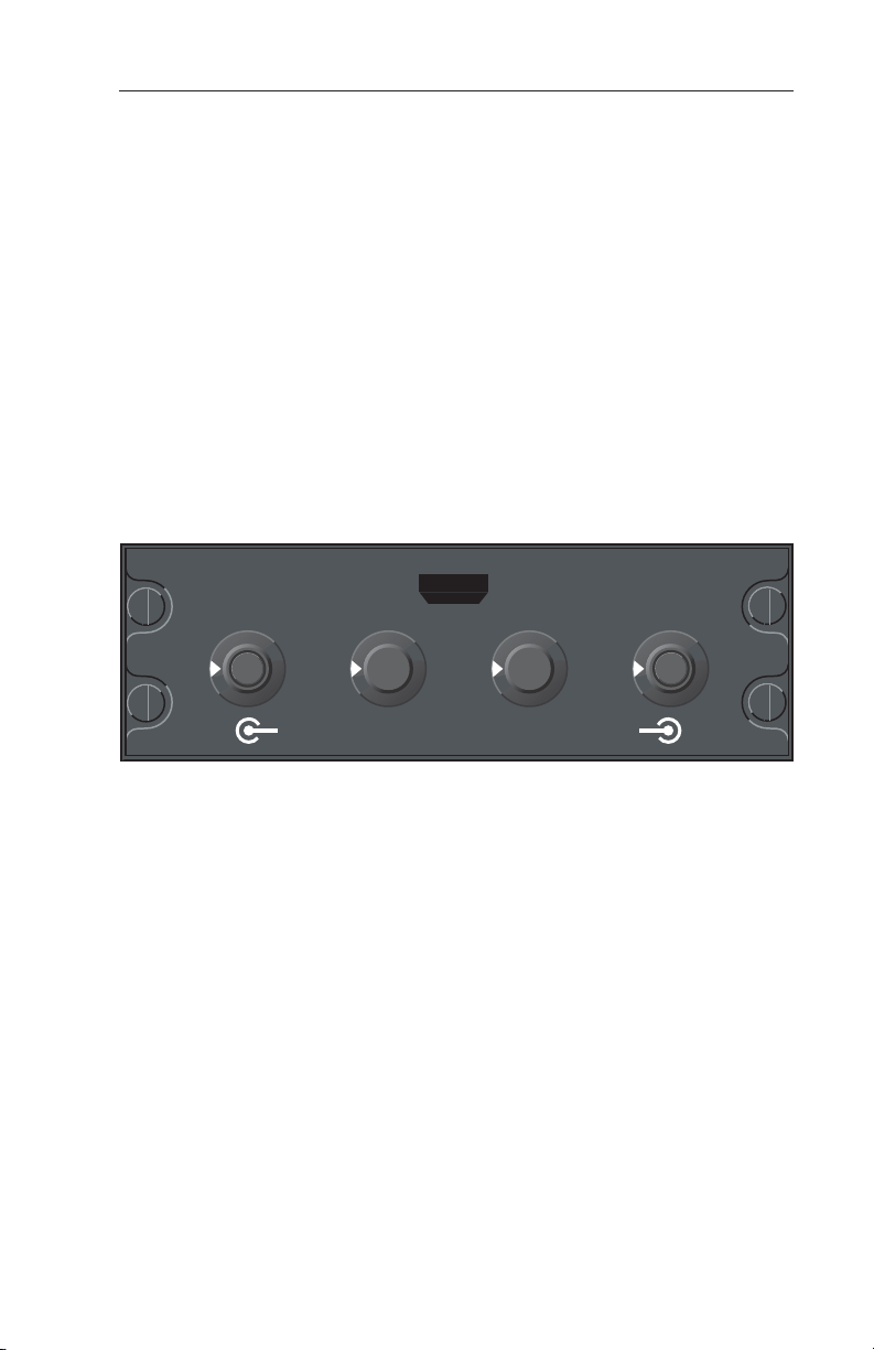
TA/VSI & TID CONTROLS
RANGE SELECT
Pressing the “UP” or “DN” buttons on the front bezel will
increase or decrease the selected display range. The “04”
software versions of the TA/VSI and all TID 66A/D units will
have selectable ranges of 3, 5, 10, 15, 20, and 40 nm. The
range selections on earlier TA/VSI units will be 3, 5, 10,
15 nm OR 5, 10, 20, & 40 nm, depending upon aircraft
wiring.
BRT CONTROL
This knob controls the brightness of the traffic display
screen.
TA SEL MODE ( IVA 81A/C/D ONLY)
Depending on the configuration strapping of the display,
the TA SEL MODE button will respond in one of two ways.
LIGHT SENSOR
The light sensor in the lower left corner controls the automatic dimming function that adjusts the display brightness
to compensate for changing ambient lighting levels.
Configuration Operation
Traffic Sel Traffic is only shown when a “TA” intruder is present. If the
display is “decluttered” and a “TA” becomes present, traffic
is displayed. Pressing the button “declutters” the display of
traffic. Traffic is again displayed upon any of the following
events:
1. The button is pressed again while a “TA” intruder is still
present.
2. A new “TA” intruder becomes present.
3. An existing intruder turns into a “TA.”
33
Effective Date 2/06006-08746-0000 Rev 7
Page 38

Controls and Displays
Compatible Weather Radar Indicators
Brand Model
Bendix King
Collins
Honeywell
RDS-81,82,84,86 & RDR 2000/2100
WXR System with IND-270
200/300SL/400/870/P90/650/800
G
C
3
6
2
A
B
BENDIX
TST
SBY
OFF
GAIN
UP
0
DN
BRT
Wx
VP
MAP
RNG
TRK
RNG
TILT
ON
NAV
TRK
LOG
RNG 5
+10
-02
WX ON
TEST
-10
MODE & FAILURE ANNUNCIATIONS
The following annunciations can be seen in the lower left-hand corner
of the TA/VSI or TID 66A/D.
(IVA 81A/C/D) (TID 66A/D)
Annunciation
TCAS STBY (Blue) (Blue) NO TCAS
TEST (Yellow) (Yellow) TEST Mode
TA ONLY (Blue) (Blue) TA ONLY Mode
TCAS (Yellow) (Yellow) FLAG (TCAS FAIL)
WEATHER RADAR INDICATORS
RDS 81, 82, 84 & 86, RDR 2000, RDR 2100 and Primus /Collins
Color Indicators
The GC 362A TCAS Graphic Processor allows TCAS traffic to be displayed on a variety of Color Radar indicators. A T/Wx
(TCAS/Weather) select button is required to switch between Weather
Only, Weather with TCAS Traffic overlaid and TCAS Only display
modes. The T/Wx switch may be a separate momentary push button
or included on another control panel.
Color Color Indicates
Effective Date 2/06 006-08746-0000 Rev 7
34
Page 39

Controls and DisplaysCAS 66A Pilot's Guide
WEATHER ONLY MODE
In this mode of operation,
only weather radar information is displayed until a
Traffic Advisory is issued by
the TCAS Processor. The
range is controlled by the
weather radar range control
in this mode of operation.
When a Traffic Advisory
occurs, the display will revert
to the default TCAS display
WX
TA AUTO
20
(either TCAS Only or
Weather/TCAS Overlay)
selected during installation by the pop-up default discrete. When
TCAS determines the Traffic Advisory is over, the display will revert to
the weather radar picture. The TCAS mode is annunciated by TA
AUTO in the lower left hand corner of the screen.
WEATHER WITH TCAS TRAFFIC MODE
A full time TCAS display
overlays the weather display
in this mode. The display
origin may be either at the
bottom of the screen or the
center of the screen,
depending on the specific
installation. Weather will be
displayed in the upper 90° or
120° sector, depending on
which radar is being used.
Weather is blanked in the
areas where TCAS traffic is
displayed. The range displayed in this mode is that which was selected for weather radar. If weather radar is in the standby mode or other
non-radar mode, the display will be the same as that in the TCAS
Only mode. This mode is maintained unless another mode is manually selected. The TCAS operational mode is annunciated along with
the pilot selected weather radar mode in the lower left hand corner of
the screen unless the radar is in standby, in which case the TCAS
mode is displayed in the upper right hand corner.
80
60
40
35
Effective Date 6/94006-08746-0000 Rev 2
Page 40

Controls and Displays
TCAS ONLY MODE
In this mode the screen’s
origin point is 1/3 up from
RNG 5
the bottom of the screen.
Only TCAS information is
displayed. This mode is
maintained unless another
-05
+25
mode is manually selected.
The range displayed is that
selected on the TCAS control panel. A 2 nm range
ring is displayed on ranges
TA ONLY
3, 5,10, and 15 nm. The
2 nm range ring consists of discrete dots (cyan) at each of the 12
o'clock positions. The 2 nm range ring is not displayed on ranges 20
and 40 nm; instead, a half-range ring is displayed. The half-range ring
consists of discrete dashes (cyan). The TCAS operational mode is
annunciated in the lower left hand corner of the screen.
Note: On the “TCAS ONLY” display “WX ON” will be annunciated in
the upper right hand corner if the weather radar is transmitting. See
Weather Radar operating guide.
At power-up the screen initially displays the Radar with TCAS Overlay
mode. When the Test mode is selected on the TCAS control panel
the self test pattern is displayed unless TCAS system failures are
detected. If system failures are detected the screen is blanked and a
list of faults is displayed.
WX & TCAS MESSAGE FORMATS
TCAS Mode Annunciations:
TEXT
TCAS STBY (Blue) TCAS in Standby
TEST (Blue) TCAS in TEST
TA ONLY (Blue) TA ONLY Mode
TA AUTO (Blue) TA ONLY Pop-Up
Note: When the Radar is placed in Standby, the TCAS mode annunciation is moved to the upper right hand corner and the display is in
the WX only or TCAS/WX modes.
Effective Date 6/94 006-08746-0000 Rev 2
Color Description
36
Page 41

Controls and DisplaysCAS 66A Pilot's Guide
TCAS Fault Annunciations:
Weather Only and Weather with TCAS Mode.
In the event of a failure, all TCAS information will be removed from the
display. One of the following failure messages will be annunciated in
the upper left corner of the screen.
TEXT
TCAS (Yellow) TCAS System Failure.
GP FAIL (Yellow) GC362A Failure.
Additional failure information will be available in the TCAS ONLY
mode, if the failure will permit mode change.
Color Description
TCAS ONLY mode
In the event of a failure, all TCAS Information will be removed from the
display. If the failure will disallow mode change, the mode shall revert
to the Weather Only mode and the fault shall be displayed as above.
Otherwise, one or more of the following failure message will be
annunciated in yellow text.
TCAS SYSTEM FAIL TCAS PROCESSOR
UPPER ANTENNA LOWER ANTENNA
RADIO ALT #1 RADIO ALT #2
ATTITUDE HEADING
TRAFFIC DISPLAY #1 TRAFFIC DISPLAY #2
RA DISPLAY # 1 RA DISPLAY # 2
ALT DATA #1 & #2 GP RAM
NO RADAR 429 DATA NO TCAS 429 DATA
37
Effective Date 6/94006-08746-0000 Rev 2
Page 42

Controls and Displays
TTHHIISS PPAAGGEE IINNTTEENNTTIIOONNAALLLLYY LLEEFFTT BBLLAANNKK
Effective Date 6/94
38
006-08746-0000 Rev 2
Page 43

Operational ProceduresCAS 66A Pilot's Guide
RNG 5
+10
-10
-02
TEST
SECTION III: OPERATIONAL PROCEDURES
TCAS I Traffic Display Test Page
SECTION III DESCRIBES OPERATION OF THE TCAS I SYSTEM.
39
Effective Date 6/94006-08746-0000 Rev 2
Page 44

Operational Procedures
TCAS OPERATING PROCEDURES
TCAS warns the operator with an aural and visual Traffic Advisory
whenever TCAS detects another transponder equipped aircraft and
predicts the Intruder to be a threat. The pilot should not initiate evasive maneuvers using information from the traffic display only or on a
traffic advisory (TA) only, without visually sighting the traffic. These
displays and advisories are intended only for assistance in visually
locating the traffic and lack the resolution necessary for use in evasive
maneuvering. The flight crew should attempt to visually acquire the
intruder aircraft and maintain/attain a safe separation in accordance
with the regulatory requirements and good operating practice. If the
flight crew can not acquire the aircraft, air traffic control should be contacted to obtain any information that may assist concerning the intruder aircraft. Based on the above procedures minor adjustment to the
vertical flight path consistent with air traffic requirements are not considered evasive maneuvers.
BEFORE TAKEOFF
TCAS should be tested using the pilot initiated self test feature during
cockpit preparation. After passing self test, TCAS should remain in
SBY before takeoff.
TCAS Traffic on the Radar Display:
If the weather radar indicator is used as the TCAS Traffic Display,
select Radar to “STBY”, “TST” or “ON”. Note that the weather radar
RT is radiating when in the radar is On. See the weather radar operator’s guide for proper radar operation. Select the “T/WX”
(TCAS/Weather) Display Mode switch to display TCAS, i. e., “TA
AUTO” or “TA ONLY”.
Before taking the active runway, TCAS should be turned ON. Range,
if available, may be selected to 10 nm or lower. Above/Norm/Below, if
available, may be selected to ABOVE.
FLIGHT PROCEDURES
The TCAS TA (traffic advisory) should alert the flight crew to use extra
vigilance to identify the Intruding aircraft. Any time the traffic symbol
becomes a yellow circle or “TRAFFIC, TRAFFIC” is announced in the
cockpit, conduct a visual search for the Intruder. If successful, maintain visual acquisition to ensure safe separation.
Effective Date 5/99 006-08746-0000 Rev 5
40
Page 45

Operational ProceduresCAS 66A Pilot's Guide
Use of the TCAS self-test function in-flight will inhibit TCAS operation
for up to eight seconds.
During initial departure, select the 10 nm TCAS range or lower
because the traffic density is the greatest near the airport.
During the climb phase of flight, select the 10 nm range or greater and
continue to use the Above display volume mode, if available. If a TA
occurs, select the 10 nm range or lower on the TCAS traffic display.
During cruise, the longer TCAS ranges may be used. The
Above/Norm/Below selection should be NORM. A 10 NM (or greater)
range may be selected for high altitude cruise.
During Descent and Approach, Below may be selected using the
Above/Norm/Below switch. A TCAS range of 10 nm or lower may be
used.
1. If a stall warning occurs during a TA, immediately execute the stall
recovery procedure. TCAS will continue to provide TA alerts during a
stall warning.
2. If a TA occurs while in the landing configuration, conduct a visual
search for the Intruder. A TA does not mandate a missed approach.
3. If a TA is encountered during a high speed buffet, adjust pitch force
as necessary to reduce buffet.
4. While it is extremely rare, GPWS or Wind Shear may issue an alert
while a TA (traffic advisory) is in progress. If this occurs, TCAS will
automatically inhibit the TCAS audio alerts, but visual display of TAs
will continue.
AFTER LANDING
After departing the active runway, TCAS should be turned to Standby
(SBY) or Off.
Post Flight
If a failure of the TCAS system has occurred, give Maintenance as
much specific information about the problem as possible. Avoid
phrases such as “TCAS Inop.” Provide information in terms of fault
lights lit, audio announcements, test pattern discrepancies and screen
annunciations that indicate which unit was observed to have failed.
41
Effective Date 8/98006-08746-0000 Rev 4
Page 46

Operational Procedures
TTHHIISS PPAAGGEE IINNTTEENNTTIIOONNAALLLLYY LLEEFFTT BBLLAANNKK
Effective Date 6/94
42
006-08746-0000 Rev 2
Page 47

System ConsiderationsCAS 66A Pilot's Guide
SECTION IV: SYSTEM CONSIDERATIONS
TID 66A/D Traffic Display
SECTION IV EXPLAINS CONSIDERATIONS OF THE TCAS I
SYSTEM; WARNINGS AND LIMITATION, AND NOTES.
43
Effective Date 2/06006-08746-0000 Rev 7
Page 48

System Considerations
LIMITATIONS AND NOTES
LIMITATIONS
Refer to the Airplane Flight Manual .
NOTES
The capability of TCAS is dependent upon the type of transponder
in the Intruding aircraft:
The Intruding aircraft must be equipped with a properly operating
transponder for normal TCAS operation. TCAS is unable to detect
any aircraft without an operating transponder.
If the Intruder is Non-Altitude Reporting (NAR), TCAS will display
only the range and bearing. It can issue a TA (Traffic Advisory)
based on distance and direction of flight. TCAS assumes NonAltitude Reporting (NAR) traffic is at the same altitude as your own
aircraft.
Intruders considered on the ground by the system will not be displayed.
Wiring options for TCAS also include the following:
* TCAS can be wired to display all traffic full time or all traffic only
as a result of the presence of a TA.
* The maximum number of targets displayed (3 - 30) can be
selected by strapping.
* The TCAS display may have pilot selectable range or may be a
fixed range controlled by the aircraft wiring.
* The TCAS system can be automatically placed in standby when
the aircraft is on the ground.
* The manually initiated system self test can be inhibited in flight.
* An aircraft lamp test switch can be wired to control the TID
66A/D & IVA 81A/C/D sequential lamp test.
* TCAS can be wired to give GPWS and Wind Shear a higher
aural warning priority.
If a radio altimeter is installed, the TCAS I aural warning (TRAFFIC, TRAFFIC) is inhibited below 400 feet AGL during descent and
below 600 feet during ascent. If no radio altimeter is installed, then
the aural warning is inhibited whenever the Landing Gear is
EXTENDED.
Effective Date 2/06 006-08746-0000 Rev 7
44
Page 49

System ConsiderationsCAS 66A Pilot's Guide
NOTES (CON'T)
It is possible to see an aircraft flying the same course and direction as your own aircraft, yet TCAS may not consider it a threat.
TCAS calculates the closure rate of the Intruder, and derives the
time to the Closest Point of Approach (CPA). If there is no closure
rate, no advisory will be issued, unless the Intruder is very close
(within approximately 0.2 mile). Conversely, traffic at the same
altitude very far ahead (about 10 miles) may be shown as a TA by
TCAS because of a very rapid closure rate.
45
Effective Date 5/99006-08746-0000 Rev 5
Page 50

System Considerations
TTHHIISS PPAAGGEE IINNTTEENNTTIIOONNAALLLLYY LLEEFFTT BBLLAANNKK
Effective Date 6/94
46
006-08746-0000 Rev 2
Page 51

APPENDIX: TCAS I SELF TEST
RNG 5
+10
-02
WX ON
TEST
-10
AppendixCAS 66A Pilot's Guide
A DESCRIPTION OF TCAS I SELF TEST.
THE APPENDIX INCLUDES
47
Effective Date 6/94006-08746-0000 Rev 2
Page 52

Appendix
TCAS SELF TEST
The TCAS self test determines the operational status of the entire TCAS
system. Select self test on the TCAS control panel. Once begun, self
test continues automatically for approximately eight seconds. During
self test, normal TCAS operation is inhibited. For optimum display during self test, selection of the 5 nm range is recommended.
If the traffic display is a weather radar indicator and the indicator is
OFF, turn On the indicator before selecting TCAS self test. The warm
up time for weather radar indicators is about five seconds.
During the first few seconds of the test sequence, the traffic display
allows verification of each type of Intruder symbol. The test generates
the symbols arranged as shown. The traffic display annunciates the
word TEST. If the weather radar is in the TEST function, this pattern
appears over the radar test pattern. If in a weather function, this test
appears over the weather.
Use of the TCAS self test function in flight will inhibit normal
TCAS operation for up to 15 seconds. For this reason, the pilot
should use caution when initiating the test in flight.
IVA 81A/C/D & TID 66A/D TCAS I Test Patterns; 5NM range
A Traffic Advisory (yellow circle) will appear at 9 o’clock, range of 2
miles, 200 feet below and climbing.
Proximity traffic (solid white diamond) will appear at 1 o’clock, range
3.6 miles, 1000 feet below, descending.
Non-Threat traffic (open white diamond) will appear at 11 o’clock,
range of 3.6 miles, flying level 1000 feet above.
Effective Date 2/06 006-08746-0000 Rev 7
48
Page 53

AppendixCAS 66A Pilot's Guide
At the conclusion of a successful Self Test, a synthesized voice
announces:
“TCAS SYSTEM TEST OK”
FAILURE CONDITIONS:
Should a failure be detected during self test, the audio message says:
“TCAS SYSTEM TEST FAIL”
A “TCAS” flag will be annunciated on the traffic display. A self test failure may indicate that the auxiliary equipment required for TCAS is not
operational. Check the associated equipment.
If the traffic display is a radar indicator, the appropriate failure message will be displayed. See WX & TCAS Message Format in Section
II: Controls and Displays.
Should a VSI failure be detected at any time, the VSI flag will appear
on the TA/VSI (IVA 81A/C/D). A “VSI” flag is not caused by the TCAS
processor.
CP 66A/B CONTROL PANEL TEST
Pressing the TST button on the CP 66A/B initiates a comprehensive
TCAS self test lasting approximately eight seconds. The system will
return to the previously selected modes when the test is complete.
IVA 81A/C/D & TID 66A/D OPTIONAL LAMP TEST
The optional lamp test produces an array of traffic in the pattern
shown. The climb/descend color bands alternate between green and
red, lasting for two seconds each. The bands are blank for a one second interval in between.
Note: The VSI function of the TA/VSI ( IVA 81A/C/D) will not be
observed during the lamp test.
RADIO ALTIMETER
If RALT is installed and is inoperative, TCAS will be Inoperative.
49
Effective Date 2/06006-08746-0000 Rev 7
Page 54

Appendix
GLOSSARY OF TCAS TERMS
ABBREVIATIONS AND DEFINITIONS
AFM or AFMS Airplane Flight Manual or Airplane Flight Manual
Supplement.
AGL Above Ground Level. Height above the ground.
ATC Air Traffic Control. A federally operated ground based system
that manages aircraft traffic flow.
ATCRBS ATC Radar Beacon System. A ground based secondary
radar and airborne transponder system used to monitor traffic.
Absolute Altitude The altitude shown on a traffic display is described
as Absolute whenever the FL mode has been selected. Otherwise,
TCAS displays the Relative Altitude between your own aircraft’s pressure altitude and the encoded altitude of the Intruder aircraft.
Altitude Tag Data tag shown above or below threat symbol giving
the relative altitude of the Intruder.
BITE Built-In Test Equipment. A feature of TCAS that continuously
monitors itself for operational errors.
CPA Closest Point of Approach. CPA refers to predicted point at
which the Intruder will be closest to your own aircraft.
FLFlight Level. This is a TCAS mode that allows the annunciation of
Absolute Altitude on the traffic display. The traffic display will indicate
the altitude in hundreds of feet, I. E., 190 is 19,000 feet.
Indicated Altitude Altitude shown on the altimeter with barometric
correction setting set to local sea level pressure. Indicated altitude is
used by the crew below 18,000 feet but not used for TCAS processing.
Intruder Any aircraft that is in the surveillance range of TCAS.
LRU Line Replaceable Unit. A self-contained avionics component
that can be replaced in the field.
Mode A Transponder ATCRBS transponder that replies to ATC
interrogations sending identification code but without giving altitude
data.
Mode C Transponder ATCRBS transponder that replies to ATC
interrogations giving identification code or encoded altitude data.
Effective Date 6/94 006-08746-0000 Rev 2
50
Page 55

AppendixCAS 66A Pilot's Guide
Mode S Transponder Transponder that replies to ATC interrogations giving an ATCRBS identification code, encoded altitude and
other data fields including discrete aircraft address and airspeed capability.
NAR Non-Altitude Reporting traffic.
Non-Threat Intruder An aircraft that has entered the TCAS surveil-
lance volume at a distance greater than 5 miles or altitude greater
than 1200 feet above or below your own aircraft.
Pressure Altitude Indicated altitude when barometric pressure is set
to 29.92” Hg. (1013mb). Pressure altitude is used by TCAS to determine the relative altitude of traffic.
Proximity Intruder An aircraft that is within 5 miles range and within
1200 feet above or below your own aircraft but does not meet the
TCAS definition of a threat.
Rad Alt or RALT Radio Altitude is the height above the ground as
determined by a radio altimeter. RALT isused by TCAS to inhibit TAs
close to the surface. Radio altitude above terrain is absolute. As
such, RALT height is sometimes referred to as absolute altitude in
some systems. RALT systems typically function below 2,500 ft AGL.
Relative Altitude The difference in altitude between two aircraft.
TCAS calculates relative altitude as the difference between your own
aircraft’s pressure altitude and the encoded pressure altitude of the
Intruder.
Self Test A functional test that determines equipment status. Self
test differs from BITE performance monitoring because it is initiated by
the crew and is not performed continually or automatically.
Sensitivity Level TCAS I has two sensitivity levels (SL). SL A shall
be automatically invoked using the following order of precedence: (1)
when the TCAS aircraft is below 2,000 feet AGL (if equipped with
radio altimeter) OR (2) when the landing gear is Extended (no radio
altimeter installed). SL B occurs under all other flight conditions. If
aircraft is not equipped with either a radio altimeter or retractable landing gear, TCAS I shall stay in SL B at all times.
Surveillance Volume The volume of airspace surrounding your aircraft that TCAS scans for Intruding traffic. The TCAS system scans
approximately 40 NM in front of and 9000 feet above and below the
aircraft. The volume will automatically begin to decrease when flying
into a high density area and may be reduced to approximately 15 NM
in front of the aircraft.
51
Effective Date 6/94006-08746-0000 Rev 2
Page 56

Appendix
TA Traffic Advisory. An audio and visual indication that another aircraft is a potential threat.
TA/VSI Traffic Advisory/Vertical Speed Indicator. A flight instrument
that gives standard VSI indication and plan position of TCAS traffic.
Threat An aircraft that has satisfied TCAS threat detection logic and
thus requiring a Traffic Advisory.
Effective Date 6/94 006-08746-0000 Rev 2
52
Page 57

Honeywell International Inc.
One Technology Center
23500 West 105th Street
Olathe, Kansas 66061
FAX 913-791-1302
Telephone: (913) 712-0400
Copyright ©1994-1999, 2004, 2005 Honeywell International Inc.
All rights reserved.
006-08746-0000
Rev 7 2/06
n
 Loading...