

Page 1
Page 2

Honeywell International Inc.
23500 W 105th Street
Olathe, KS 66061
U.S.A
CAGE: 22373
Telephone: (800) 601-3099 (U.S.A./ Canada)
Telephone: (602) 365-3099 (International)
AV8OR 3D
© Honeywell International Inc.
User’s Guide
Page 3

AV8OR 3D User Guide
Honeywell-Confidential
THIS COPYRIGHTED WORK AND ALL INFORMATION
ARE THE PROPERTY OF HONEYWELL
INTERNATIONAL INC., CONTAIN TRADE SECRETS
AND MAY NOT, IN WHOLE OR IN PART, BE USED,
DUPLICATED, OR DISCLOSED FOR ANY PURPOSE
WITHOUT PRIOR WRITTEN PERMISSION OF
HONEYWELL INTERNATIONAL INC. ALL RIGHTS
RESERVED.
Honeywell Materials License Agreement
The documents and information contained herein ("the
Materials") are the proprietary data of Honeywell
International Inc. and Honeywell Intellectual Properties
Inc (collectively "Honeywell"). These Materials are
provided for the exclusive use of Honeywell Service
Centers; Honeywell-authorized repair facilities;
operators of Honeywell aerospace products subject to
an applicable product support agreement, their wholly
owned-subsidiaries or a formally designated third
party service provider thereunder; and direct
recipients of Materials from Honeywell's Aerospace
Technical Publication Distribution. The terms and
conditions of this License Agreement govern your use
of these Materials, except to the extent that any terms
and conditions of another applicable agreement with
Honeywell regarding the operation, maintenance, or
repair of Honeywell aerospace products conflict with
the terms and conditions of this License Agreement, in
which case the terms and conditions of the other
agreement will govern. However, this License
Agreement will govern in the event of a conflict
between its terms and conditions and those of a
purchase order or acknowledgement.
1. License Grant - If you are a party to an applicable product
support agreement, a Honeywell Service Center agreement, or
an authorized repair facility agreement, Honeywell hereby grants
you a limited, non-exclusive license to use these Materials to
.
© Honeywell International Inc.
Page 4

AV8OR 3D User Guide
operate, maintain, or repair Honeywell aerospace products only
in accordance with that agreement.
If you are a direct recipient of these Materials from Honeywell's
Aerospace Technical Publication Distribution and are not a party
to an agreement related to the operation, maintenance or repair
of Honeywell aerospace products, Honeywell hereby grants you a
limited, non-exclusive license to use these Materials to maintain
or repair the subject Honeywell aerospace products only at the
facility to which these Materials have been shipped ("the
Licensed Facility"). Transfer of the Materials to another facility
owned by you is permitted only if the original Licensed Facility
retains no copies of the Materials and you provide prior written
notice to Honeywell.
2. Rights In Materials - Honeywell retains all rights in these
Materials and in any copies thereof that are not expressly granted
to you, including all rights in patents, copyrights, trademarks, and
trade secrets. No license to use any Honeywell trademarks or
patents is granted under this License Agreement.
3. Confidentiality - You acknowledge that these Materials
contain information that is confidential and proprietary to
Honeywell. You agree to take all reasonable efforts to maintain
the confidentiality of these Materials.
4. Assignment And Transfer - This License Agreement may be
assigned to a formally designated service designee to the extent
allowed under an applicable product support agreement or
transferred to a subsequent owner or operator of an aircraft
containing the subject Honeywell aerospace products. However,
the recipient of any such assignment or transfer must assume all
of your obligations under this License Agreement. No assignment
or transfer shall relieve any party of any obligation that such party
then has hereunder.
5. Copies of Materials - Unless you have the express written
permission of Honeywell, you may not make or permit making of
copies of the Materials. Notwithstanding the foregoing, you may
make copies of only portions of the Material for your internal use.
You agree to return the Materials and any copies thereof to
Honeywell upon the request of Honeywell.
6. Term - This License Agreement is effective until terminated as
set forth herein. This License Agreement will terminate
immediately, without notice from Honeywell, if you fail to comply
with any provision of this License Agreement or will terminate
simultaneously with the termination or expiration of your
applicable product support agreement, authorized repair facility
.
© Honeywell International Inc.
Page 5

AV8OR 3D User Guide Honeywell
agreement, or your formal designation as a third party service
provider. Upon termination of this License Agreement, you will
return these Materials to Honeywell without retaining any copies
and will have one of your authorized officers certify that all
Materials have been returned with no copies retained.
7. Remedies - Honeywell reserves the right to pursue all
available remedies and damages resulting from a breach of this
License Agreement.
8. Limitation of Liability - Honeywell does not make any
representation regarding the use or sufficiency of the Materials.
THERE ARE NO OTHER WARRANTIES, WHETHER WRITTEN
OR ORAL, EXPRESS, IMPLIED OR STATUTORY, INCLUDING,
BUT NOT LIMITED TO, (i) WARRANTIES ARISING FROM
COURSE OF PERFORMANCE, DEALING, USAGE, OR TRADE,
WHICH ARE HEREBY EXPRESSLY DISCLAIMED, OR (ii)
WARRANTIES AGAINST INFRINGEMENT OF INTELLECTUAL
PROPERTY RIGHTS OF THIRD PARTIES, EVEN IF
HONEYWELL HAS BEEN ADVISED OF ANY SUCH
INFRINGEMENT. IN NO EVENT WILL HONEYWELL BE LIABLE
FOR ANY INCIDENTAL DAMAGES, CONSEQUENTIAL
DAMAGES, SPECIAL DAMAGES, INDIRECT DAMAGES, LOSS
OF PROFITS, LOSS OF REVENUES, OR LOSS OF USE, EVEN
IF INFORMED OF THE POSSIBILITY OF SUCH DAMAGES. TO
THE EXTENT PERMITTED BY APPLICABLE LAW, THESE
LIMITATIONS AND EXCLUSIONS WILL APPLY REGARDLESS
OF WHETHER LIABILITY ARISES FROM BREACH OF
CONTRACT, WARRANTY, TORT (INCLUDING BUT NOT
LIMITED TO NEGLIGENCE), BY OPERATION OF LAW, OR
OTHERWISE.
9. Controlling Law - This License shall be governed and
construed in accordance with the laws of the State of New York
without regard to the conflicts of laws provisions thereof. This
license sets forth the entire agreement between you and
Honeywell and may only be modified by a writing duly executed
by the duly authorized representatives of the parties.
.
© Honeywell International Inc.
Page 6

AV8OR 3D User Guide Honeywell
Copyright - Notice
Copyright 2008, Honeywell International Inc. All rights reserved.
Honeywell is a registered trademark of Honeywell International
Inc.
All other marks are owned by their respective companies.
.
© Honeywell International Inc.
Page 7

User Guide:
Version: 4.3 Size: 7 x 9 Mode: Printing 5/23/06
DRAFT – FOR REVIEW ONLY
Contents
Welcome to AV8OR 3D vii
A Word of Caution
About This Manual vii
Chapter 1 Quick Start Guide 1
Overview
Your Tablet PC 1
Installing AV8OR 3D in Your Aircraft 1
Activating Your XM Satellite Receiver 2
Understanding the AV8OR 3D Display 3
Using Buttons and On-screen Menus 7
Using On-screen Menus 8
Shutting Down AV8OR 3D 11
1
Top Information Area 4
Bottom Information Area 4
Altimeter 5
Course Deviation Indicator 6
Using Tablet PC Buttons and Main Display Items 7
vii
Chapter 2 Installing AV8OR in Your Aircraft 13
Installing the INU and Antenna
INU Panel Indicators 14
Attaching the Mount 14
Connecting the Power Supply and Cables 15
AV8OR 3D User Guide i
13
Page 8

Contents
Chapter 3 Flying with AV8OR 3D 17
Preparing for Flight
Starting the INU 17
Starting the Tablet PC 17
Error Messages 19
Starting the Weather Service 19
Selecting the Barometer or GPS 21
Creating a Flight Plan 21
Viewing Airport Diagrams and Approach Plates 25
In Flight 26
Displaying Views 26
Checking the Weather 32
Terrain Awareness (TAWS) 38
Navigating 39
Creating a Direct To 39
Radar Vectors 44
Amending Your Flight Plan 45
Displaying the Nearest Object 46
Activating Approach Procedures 48
Shutting Down AV8OR 3D 50
Using the Simulator Mode 50
17
DRAFT
Chapter 4 Configuring Your AV8OR 3D 53
Configuration Settings
Display Settings 54
Time and Date 56
INU and Simulator 57
GPS 59
Power 60
XM Information 61
Weather 62
Display Filters 63
Log Flights 64
Downloading Databases, Updates, and Manuals 65
53
ii AV8OR 3D User Guide
Page 9

DRAFT
Appendix A Safety, License Agreement, Warranty, and Technical
Support 67
Important Safety Precautions and Environmental Specifications
Electrical Safety 67
Battery 67
Pollution Degree Category 67
Other Required Disclosures and Compliances 67
CSA Approval 67
End User License Agreement 68
Warranty 71
Technical Support 75
Contents
67
AV8OR 3D User Guide iii
Page 10

Contents
DRAFT
iv AV8OR 3D User Guide
Page 11

User Guide:
Version 4.4 Size: 7 x 9 Mode: Printing 5/23/06
DRAFT – FOR REVIEW ONLY
Welcome to AV8OR 3D
Thank you for purchasing AV8OR 3D, the first portable multifunction flight
display (MFD) with 3D synthetic vision. Never before has a general aviation pilot
been able to receive such detailed geographic information in a portable unit.
Besides providing great terrain awareness, the solid state gyros and the GPS will
help you to navigate in even the most challenging situations.
A Word of Caution
Although AV8OR 3D is a situational awareness tool, AV8OR 3D is not to be used for
primary navigation. All terrain information is relative to your GPS position and
barometric pressure readings, and so is subject to error. Airports, navaids,
airspaces, as well other airport data is provided by
subject to error.
Honeywell and can also be
About This Manual
This manual is provided as a reference to help you learn about the functions and
features of AV8OR 3D. Please take a few minutes to become familiar with AV8OR 3D
features before you enter the cockpit.
AV8OR 3D User Guide
Page 12

Welcome to AV8OR 3D
DRAFT
v AV8OR 3D User Guide
Page 13

User Guide:
Chapter 1 Introduction to Software Installation
Version 4.4 Size: 7 x 9 Mode: Printing 5/23/06
DRAFT – FOR REVIEW ONLY
1
Quick Start Guide
Overview
This quick-start section will get you up and running with the basic features of
AV8OR 3D. Subsequent chapters will guide you through using AV8OR 3D from
flight planning all the way to touchdown.
After you become familiar with AV8OR 3D, you can refer to subsequent sections to
obtain information about customizing the configuration of your AV8OR 3D.
Now, let’s get started...
Your Tablet PC
While the Tablet PC is a multifunction device that you can use as a home
computer, it has been specifically configured by Honeywell to
run the AV8OR 3D. This includes display and other settings within the PC. Altering
these settings may affect AV8OR 3D functionality.
Installing AV8OR 3D in Your Aircraft
Refer to Section 2, “Installing AV8OR 3D in Your Aircraft” for details on the
following procedures:
• “Installing the INU and Antenna” on page 13.
• “Attaching the Mount” on page 14
• “Connecting the Power Supply and Cables” on page 15
AV8OR 3D User Guide 1
Page 14

Activating Your XM Satellite Receiver
DRAFT
Activating Your XM Satellite Receiver
Note: Prior to connecting the weather receiver, you must subscribe to an XM Aviator or
Aviator Lite service. Call XM Satellite at (800) 985-9200 for more information.
1. Turn on the INU and XM weather receivers with the antenna visible to
satellites.
2. Call XM Satellite and activate your subscription.
The unit must be turned on and the antenna visible to the sky for the receiver
to activate.
Note: If you have already activated your subscription but are unable to activate
your receiver, you may need to call XM Satellite and ask them to send a new
activation signal. The XM activation phone number is (800) 967-2346.
3. Wait for the XM weather receiver to be activated from an XM satellite. (It may
take from several minutes to up to 1 hour to retrieve the activation signal.)
4. Press the Menu button to display the menu items on the left side of the screen.
5. Press the Cfg button to enter the Setup dialog.
6. Select the XM info tab.
7. In the connection section, press the Start button and wait until you see the
radio signal status field switch to “Active” and the activation info is updated
with the radio serial number. If the service level field is not updated with
your subscription level, press the Activate button.
8. After being activated, your XM weather receiver will transmit the weather
data to AV8OR 3D. The section “XM Information” on page 61 provides information about the quality of the signal.
2 AV8OR 3D User Guide
Page 15
DRAF
Understanding the AV8OR 3D Display
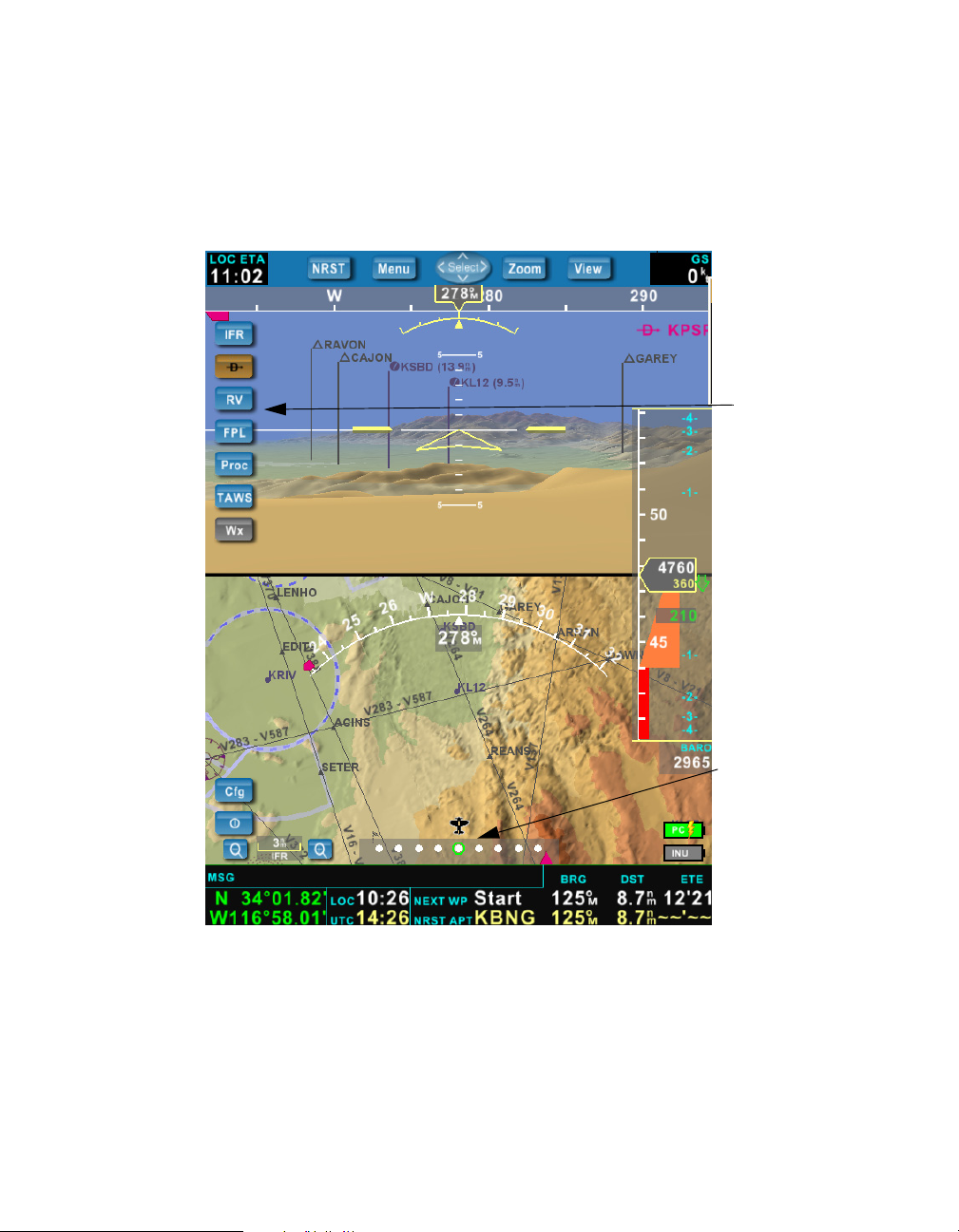
Understanding the AV8OR 3D Display
This is the main view of AV8OR 3D. It displays the terrain in 2D and 3D, along with
information about the flight.
Top Information
Area
Flight Plan
Information
Menus
Altimeter
Course Deviation
Indicator
Position Data
Area
AV8OR 3D User Guide 3
Page 16
Understanding the AV8OR 3D Display
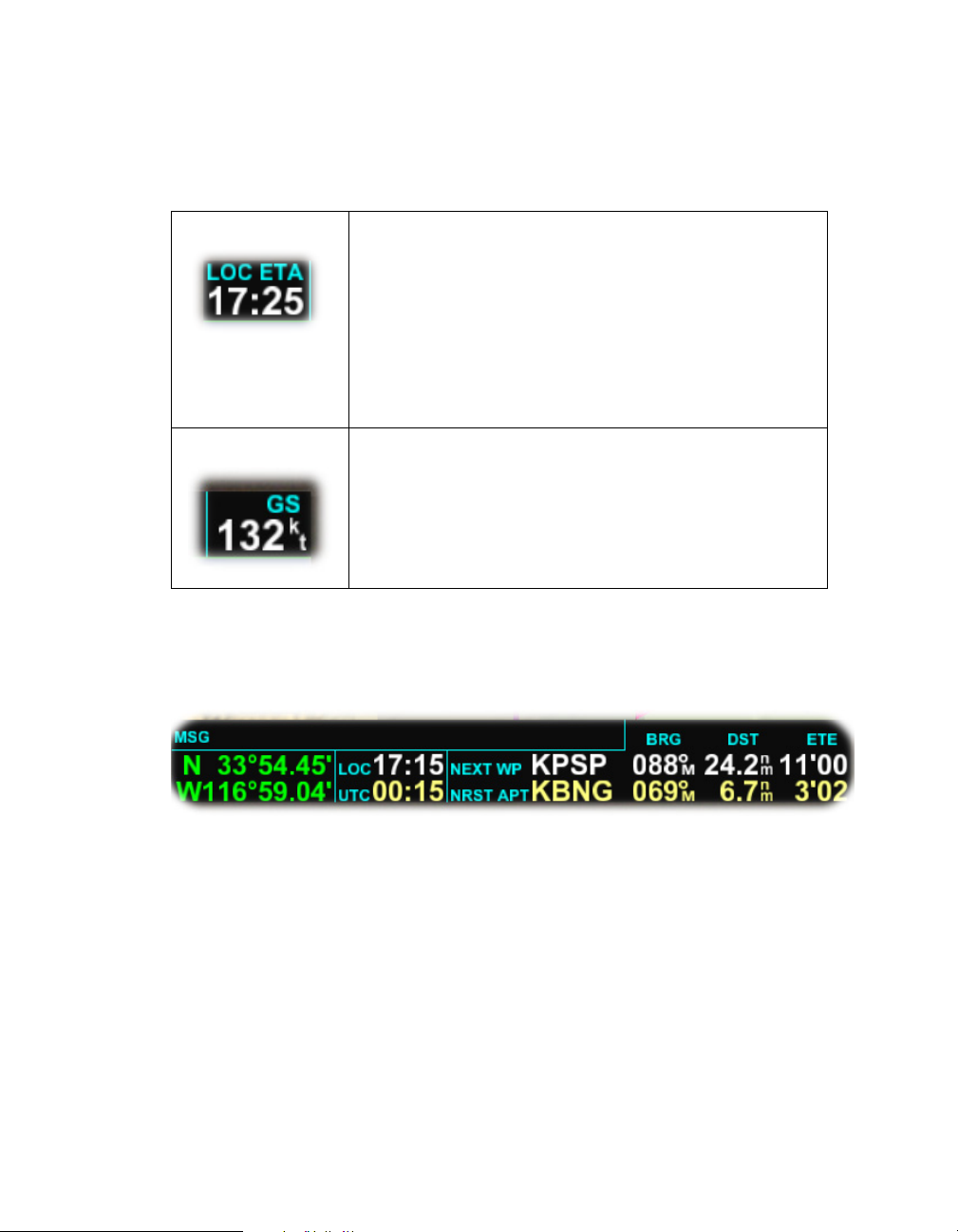
Top Information Area
The display information at the top of the tablet PC shows the following items:
DRAFT
Estimated local time of arrival
The estimated time of arrival (ETA) is given in the time
zone set on the PC, not necessarily the time zone of the
departure airport. If you cross a time zone, the ETA
will not change to reflect the time in the new time zone.
Button function/menu area: displays the functions
attached to these buttons depending on the mode you
are using:
Current ground speed in knots
Bottom Information Area
The position data area is located at the bottom of the screen. It provides a quick
reference to important flight data.
From left to right, it displays:
• position of the aircraft.
• current time expressed locally (departing airport) as well as the UTC time.
• next waypoint if a flight plan is activated, as well as the identifier of the
nearest airport. Both of these items show the bearing to it (BRG), the distance
to it (DST), and the estimated time en route (ETE) to reach that point, based
on the current ground speed of the aircraft.
4 AV8OR 3D User Guide
Page 17
DRAFT
Above this line of items is the message area (MSG) which displays important
messages such as notifying you of:
• being close to an airspace
• inside an airspace
• off course
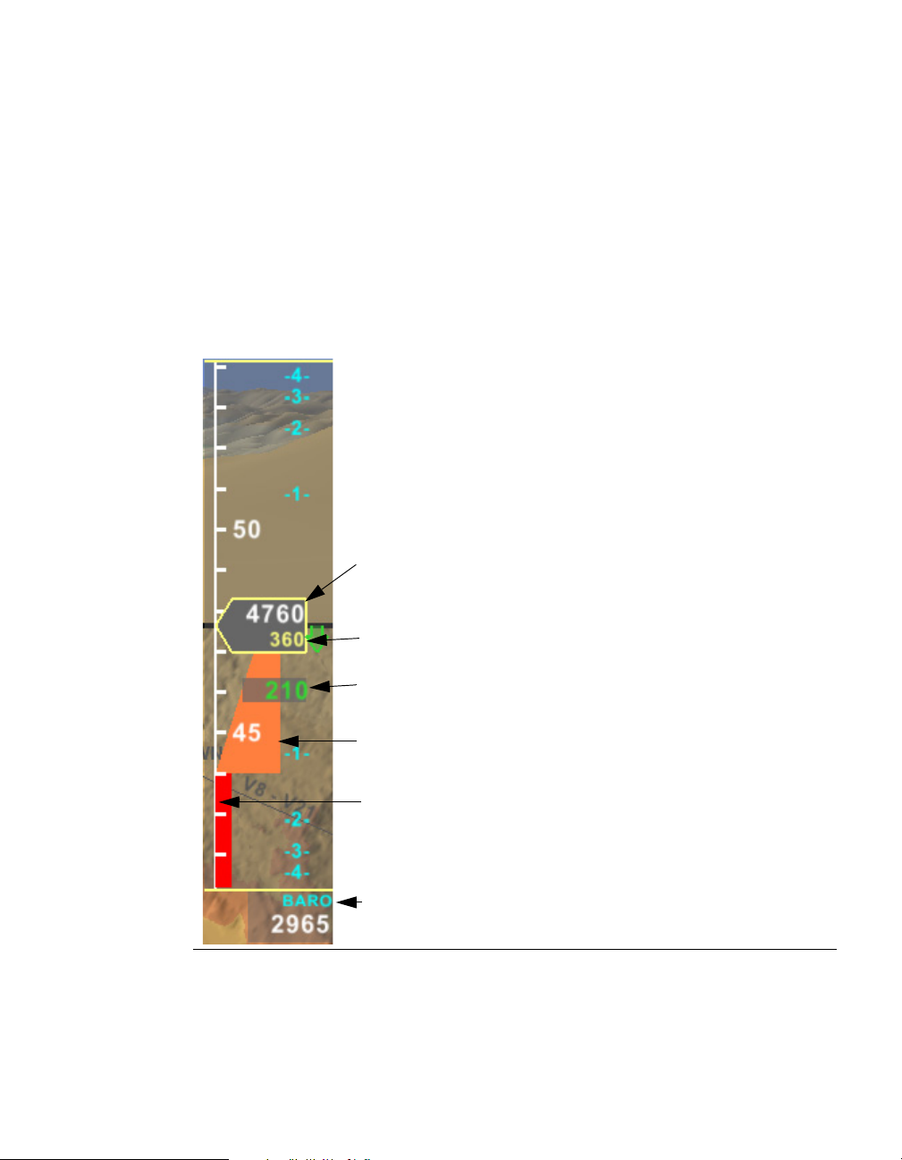
Altimeter
Altitude MSL
Understanding the AV8OR 3D Display
An altimeter is displayed on the right
side of the screen as a transparent tape,
graduated in hundreds of feet, and an
arrow outlined in yellow displaying
two current altitudes. The white value
indicates the altitude of the aircraft
above mean sea level (MSL). The
yellow value indicates the altitude of
the aircraft above the ground level
(AGL).
When you are close to the ground, an
Altitude AGL
Ver tical Speed
Ground Proximity
Ground
Barometric
Pressure
AV8OR 3D Users Guide 5
orange triangle is displayed as an alert.
The base of the triangle shows the
ground elevation. The top of the
triangle represents the terrain awareness altitude based on the settings in
the configuration menu.
Page 18

Understanding the AV8OR 3D Display
Barometric Pressure
The altitude provided is computed using the pressure sensor built into the INU,
in reference to barometric pressure at sea level or as advised by Air Traffic
Control (ATC). If barometric pressure is not available, such as in a pressurized
aircraft, GPS altitude may be alternatively selected
Vertical Speed
Vertical speed is indicated by a numeric value and a green arrow that moves next
to a blue scale within the altitude tape. The graduations on the blue scale are in
thousands of feet per minute. The position of the numeric value depends on the
direction of the vertical speed. When in level flight, the arrow and the numerical
value are not displayed.
Target Altitude
The target altitude is displayed only when an instrument procedure is activated.
It shows what the altitude of the aircraft should be at the current position in relation to the approach.
Course Deviation Indicator
DRAFT
The course deviation indicator (CDI) is only displayed when an instrument procedure or a flight plan is activated.
The direction of the deflection of the CDI depends on the position of the aircraft,
not on its track. Therefore, when the track is roughly following the course of the
activated flight plan, CDI sensing is normal. If, for example, the magenta triangle
is to the left, a left correction must be applied.
When a flight plan is activated, a full deviation represents five nautical miles; one
dot represents 1 nautical mile.
Caution: When an instrument procedure is activated, a full deviation of the
CDI represents 2.5º.
6 AV8OR 3D User Guide
Page 19

DRAFT
Using Buttons and On-screen Menus
This section describes how to display menu choices and select information in
AV8OR 3D using On-screen buttons.
Using Tablet PC Buttons and Main Display Items
The buttons are located at the top of the tablet PC. There are five buttons, and an
arrow keypad. The functions attached to these buttons change depending on the
mode you are using. Functions are always displayed directly beneath the corresponding buttons in the Top Information Area.
Nearest Button
The NRST button opens the Nearest screen which provides information about the
airports, intersections, VORs, or NDBs that are close to the position of the aircraft.
It has the same action as selecting NRST in the menu. The NRST button will
always be available to you to use regardless of which mode you are in.
Menu / Enter Button
Pressing the MENU button activates an on-screen menu containing a list of items
to be displayed on the left side of the screen. Once the on-screen menu is active,
the center button in the arrow keypad turns into an SELECT button to allow you
confirm selection of the selected menu item. See the Menu Button section for more
information.
Using Buttons and On-screen Menus
Pan /Zoom Button
The Pan/Zoom button toggles the main display between Pan and Zoom modes.
Use the arrow keypad to set zoom and pan behavior.
View Button
The VIEW button changes the type of view in the display area. Pressing the VIEW
button toggles the view between 2D, 3D, and split screen (2D/3D).
AV8OR 3D User Guide 7
Page 20

Using On-screen Menus
Arrow Keypad
The arrow keypad has three modes of use:
Zoom Mode
The up and down arrows can be used for zooming, and the left and right arrows
can be used for controlling the brightness of the display.
Pan Mode
Use the arrow keys to pan up, down, left, and right of your aircraft position, or
around airport diagrams or approach charts.
Menu Mode
While the menu is active, use the arrow keys to move up and down within the
menu. The center button in the arrow keypad can be used to select a particular
menu option.
Using On-screen Menus
AV8OR 3D has a menu providing easy access to the many features of the software.
This menu is activated by pressing the MENU button in the Top Information
Area. A list of menu items will appear on the left side of the screen. Menu items
can be opened by using either the stylus or the arrow keypad, and then pressing
Select.
DRAFT
When the menu is displayed, the left and up arrows move the cursor in the list of
items in the menu. The Select button selects the highlighted item. Pressing the
Menu button again hides the menus. It is also possible to select an item in the
menu by tapping on its button with the stylus. The following screen shows the
menu choices on the left and the table describes their functions.
8 AV8OR 3D User Guide
Page 21
DRAFT
Menu
Choices
Using On-screen Menus
AV8OR 3D User Guide 9
Page 22

DRAF
Shutting Down AV8OR 3D
To shut down AV8OR 3D:
1. Exit the AV8OR 3D program
Press the menu button and select the Exit button in the lower left portion of
the screen.
2. Power off the INU
3. Power off the tablet PC
Shutting Down AV8OR 3D
AV8OR 3D User Guide 11
Page 23

Shutting Down AV8OR 3D
DRAFT
12 AV8OR 3D User Guide
Page 24

User Guide:
Version 4.4 Size: 7 x 9 Mode: Printing 5/23/06
DRAFT – FOR REVIEW ONLY
2
Installing AV8OR 3D in Your
Aircraft
Installing the INU and Antenna
The INU battery may be partially charged when you take it out of the box. The
INU will charge itself while plugged into the electrical system during the time the
aircraft is running.
Place the INU under your seat or in another suitable position. Although the Bluetooth capability between the INU and tablet PC makes it possible to place the INU
in various locations within the aircraft, it is important that the two devices be in
close proximity to each other (within 6 ft.).
When installing the INU, you need to consider how easy it is for you to reach the
power button. Other determining factors for placement are:
• length of the power cords to your power source
• length of the GPS antenna cable
• distance of the INU from the tablet PC.
The INU should be positioned within the aircraft with its front panel facing out
toward the front of the aircraft. It must be securely attached in the most level and
stable position possible.
An optional mounting plate for the INU is also available. Visit
www.BendixKing.com or call for details.
The figure below shows the front panel view of the INU.
AV8OR 3D User Guide 13
Page 25

Attaching the Mount
INU Panel Indicators
DRAFT
• The power LED is green.
• When the GPS or INU LED is blinking, it indicates that some data packets are
being lost. This could occur for multiple reasons:
• Poor Bluetooth connection can occur if the tablet PC and the INU are too
far apart from each other or if there are obstacles between the two devices
blocking the signal. Try fixing by relocating the tablet and INU.
• INU hardware malfunction.
Attaching the Mount
An optional mounting plate is available for the tablet PC. The plate is compatible
with the RAM mounting system, with options available to fit most aircraft. (See
RAM at www.ram-mount.com)
Note: As opposed to a 2D navigation, the synthetic vision provided by AV8OR 3D is best
viewed in a heads-up manner. The tablet PC should be mounted on the yoke
panel or similar location as opposed to a knee-board mount.
14 AV8OR 3D User Guide
Page 26

DRAFT
Connecting the Power Supply and Cables
Connecting the Power Supply and Cables
Your power supply has three cables. One cable connects to the cigarette lighter,
one to the tablet PC, and the third to the INU. The INU cable has a locking,
threaded plug on the end. Insert this cable into the INU power socket.
If needed, a longer (6-ft.) power cord for the tablet is available for purchase.
A power supply clip is included in the package. This clip can be screwed under
the dash board to hold the power supply.
AV8OR 3D User Guide 15
Page 27

Connecting the Power Supply and Cables
DRAFT
16 AV8OR 3D User Guide
Page 28

User Guide:
Chapter 3 Flying with VistaNav
Version 4.4 Size: 7 x 9 Mode: Printing 5/23/06
DRAFT – FOR REVIEW ONLY
3
Flying with AV8OR 3D
The following sections will guide you through a flight using AV8OR 3D. Be sure to
familiarize yourself with the button and menu choices described in the Quick
Start section.
Preparing for Flight
Starting the INU
Switch on the INU. The EXT PWR LED light on the front of the INU will turn
green to signal there is external electrical power to the unit. If the unit is running
on battery power, the LED will not illuminate.
Starting the Tablet PC
To start the tablet PC and AV8OR 3D program:
1. Switch on the tablet PC using the sliding power switch on the top of the tablet
PC. The computer will boot up and display the standard Windows desktop.
2. Click the AV8OR 3D desktop icon or find the program in the Start menu. When
the AV8OR 3D application has started, a Welcome Screen with a map of the
U.S. is displayed. The map is color-coded to indicate on a per-region basis
whether the installed aeronautical database is current or expired.
– Green: up-to-date
– Orange: expired
AV8OR 3D User Guide 17
Page 29

Preparing for Flight
DRAFT
If the database has expired, the AV8OR 3D navigational component will still
operate normally. However, the aeronautical information will no longer be
valid and may not be accurate.
3. Acknowledge the status of the database by pressing any hardware button on
the tablet PC.
After you acknowledge the status of the database, the tablet PC will establish a
connection to the INU. Once the connection is made between the two units, the
AV8OR 3D application displays the current status of the GPS signal acquisition.
The INU requires the tracking of at least three satellite signals. Once this occurs,
the tablet PC will indicate that GPS signals are being acquired and that the unit is
ready for use. On the front of the INU, all three status LEDs will light.
Note: The INU is optimized for in-flight use. Static testing on the ground may produce
unreliable behavior.
18 AV8OR 3D User Guide
Page 30

DRAFT
Error Messages
The following error messages may appear during this initialization process:
• “Error - No Bluetooth radio component found. Please activate the Bluetooth
radio and retry. If the error persists, contact Honeywell Customer Support.”
There is a fault between the INU and tablet PC Bluetooth connection. This
could indicate that the INU and tablet PC might be two far from each other,
or there may be an obstacle between the two units causing some kind of interference. It could also indicate that the INU is not turned on. Examine your
physical connections and then choose “Retry” by pressing any tablet PC
button. If the problem persists, please co
• “Warning - INU not found. Please make sure that the INU is turned on and
retry. If the error persists, contact Honeywell Customer Support.”
The dialog will show two buttons: “Retry” and “Simulation”.
– If your intent is to use AV8OR 3D for navigation, check to make sure the
– If your intent is to use the AV8OR 3D simulation mode, click on the Simula-
Preparing for Flight
ntact Honeywell Customer Support.
INU power is turned on. Then choose Retry by pressing any tablet PC
button. If there still is no connection, please contact Honeywell Customer
Support.
tion button.
Starting the Weather Service
Turn on the XM weather receiver with the antenna visible to satellites. It may take
several minutes for the XM receiver to acquire a signal and download weather
data.
Press the Cfg button and the XM Info tab to display the status of downloaded
data. Refer to “XM Information” on page 61 for more information.
The live weather option includes the following features:
• TFR (Temporary Flight Restriction): This airspace is displayed in red on the
2D view. A TFR can have an activation date and an expiration date. By
default, a TFR is displayed if it doesn't have any activation and expiration
date, or if it already has been activated but is not expired. Three TFR
checkbox options are available in the Display tab of the Setup dialog (see
“Display Settings” on page 54).
• NEXRAD radar: This feature is activated by the WX menu. It displays the
precipitation in different colors depending on the intensity and the type of the
rain. It also displays the echo tops in different grey levels.
AV8OR 3D User Guide 19
Page 31

Preparing for Flight
• METAR/TAF: These are weather reports from the National Weather Service.
• Flight Rule Indicator: If a METAR is available for an airport, a color-coded
DRAFT
If either or both of these reports are available for a particular airport, a Wx
button will be active on the right side of the Direct To or Nearest dialog.
icon is displayed under the airport code in the 2D and the 3D view:
VFR Ceiling > 1000 ft. and Visibility 5sm
Marginal VFR Ceiling > 1000 ft. and Visibility [3sm,5sm]
IFR Ceiling < 1000 ft. and/or Visibility < 3sm
Outdated The METAR is outdated
• Winds Aloft (Aviator service only): The winds aloft feature displays wind
barbs depicting the wind direction and observed velocity. These symbols are
displayed in accordance with standard FAA symbology where the wind
direction shows from the velocity marks towards the tip of the wind barb. A
legend of symbols is provided at the bottom of the 2D display when this function is selected.
The altitude for winds aloft may be varied by pressing the “+” and “-”
buttons to the right of the Wx menu.
• Lightning (Aviator service only): Observed lightning is depicted on the 2D
map by a small lightning bolt symbol at the strike location.
• Freezing/Icing Levels (Aviator service only): Freezing or icing levels are
depicted using an area color chart. A legend of colors representing freezing
altitudes is provided at the bottom of the 2D display when this function is
selected.
20 AV8OR 3D User Guide
Page 32

DRAFT
Selecting the Barometer or GPS
To select the barometer:
1. Press the Altitude Settings box at the bottom of the altimeter tape to display
the INU/Simu tab of the Setup screen.
Preparing for Flight
2. In the Altimeter field a pull-down menu allows you to choose Barometr
tude or
Warning: Critical to safe flight:
If you choose Barometric pressure, you must enter the current area pressure
into the “Barometric Settings” field in order to have a more accurate altitude.
Since the INU pressure sensor is inside the cabin, pressure readings may vary
slightly from outside static pressure. INU barometric pressure should behave
similarly to your aircraft's alternate static source.
3. To change the altimeter setting, press the Barometric Settings field to high-
light the barometric number.
4. Use the rocker button on the top of the tablet PC to adjust the barometric
setting up or down.
5. Barometric settings may be set using either hPa (hectopascal) or inHg (inch of
mercury).
Warning: GPS altitude must be used in pressurized aircraft.
GPS altitude.
Creating a Flight Plan
To create a new flight plan:
ic alti-
1. Select Menu to display the Menu buttons on the main screen.
2. Select the FPL to display the Flight Plan screen.
The Flight plan function displays all the flight plans that were saved in the
C:\VistaNav\FlightPlans directory on the tablet PC. This includes the flight
plans generated by AV8OR 3D itself, as well as flight plans created with
compatible flight planning software that have been saved at this location.
Available flight plans may be edited, activated or deleted from the Flight Plan
screen using the menu on the right of the screen.
AV8OR 3D User Guide 21
Page 33

Preparing for Flight
DRAFT
Note: Flight plans may also be imported from other sources. For more information,
see “Downloading Databases, Updates, and Manuals” on page 65.
3. Select New from the menu on the right side of the screen. This displays the
Flight Plan Edit screen.
22 AV8OR 3D User Guide
Page 34

DRAFT
4. Name your flight plan by tapping in the Name field to display the Virtual
Keyboard and typing a name for your plan. Pressing the “<“ button to the
right of the name field will clear the field.
Preparing for Flight
AV8OR 3D User Guide 23
Page 35

Preparing for Flight
5. To enter a waypoint into the flight plan, press the Insert button. This will
DRAFT
bring you to the waypoint search screen, where you can search for Airports,
VORs, NDBs and intersections. You can press the Info, Plates, or Wx buttons
on this screen to display more information about each waypoint. Once you
have found the desired waypoint, press Insert and the selected waypoint will
be entered into the flight plan.
24 AV8OR 3D User Guide
Page 36

DRAFT
Preparing for Flight
By default, the bottom line of the flight plan “~~~~~~~” will always be highlighted, thereby adding new waypoints to the bottom of your flight plan. If
you would like to insert a new waypoint in the middle of a flight plan, simply
highlight the desired line in the flight plan before pressing Insert. The new
waypoint will be added above the highlighted line.
Waypoints may also be deleted, shifted up or down, or the entire routing can
be reversed using the menu buttons on the right of the flight plan screen.
To activate a flight plan:
Flight plans may be activated from either the Flight Plan list or the Flight Plan
Edit screen.
From the Flight Plan list screen, highlight the flight plan in the list and press the
Activ button. If you are in the Flight Plan Edit screen, simply press the Activ
button.
When activating a flight plan, the previously activated flight plan or instrument
procedure, if any, will be canceled.
Note: You must have more than one waypoint entered in order to activate a flight plan.
Viewing Airport Diagrams and Approach Plates
Airport information, including airport diagrams and approach plates, can be
accessed by either searching for an airport with the Direct-To function, the
Nearest function or by selecting an airport within a flight plan.
To view an airport:
1. From the main menu, select Direct-to (D) or NRST. This will bring you to the
airport search page.
With Airport selected in the Type field, the central table displays a list of
airports, including for each one its name, its bearing and its distance from the
aircraft position, its elevation, and the longest runway length.
2. Search for an airport by directly entering its code in the input field.
3. To enter the code with the buttons:
a. Highlight the input field
b. Press the ENTER button.
The up/down arrows change the current letter, and the right/left arrows go
to the next/previous character.
AV8OR 3D User Guide 25
Page 37

In Flight
DRAFT
When the selection is complete, press the ENTER button to validate the
choice.
The “<“button may be used at any time to clear the data entry field.
4. To enter the code with the tablet PC stylus:
a. Tap on the input field to display the virtual keyboard.
b. Select the order of the keys on the keyboard.
QWERTY (regular computer keyboard arrangement)
ABCD (alphabetically arranged).
Airports with available diagrams and/or approach plates will have the Plates
button active in the right-hand menu. Pressing Plates will bring up a list of available plates for viewing.
From the Plates list screen, you can choose to view a plate by highlighting the
plate and pressing the View button. This will open the Plate Viewer.
The Plate Viewer provides buttons allowing you to zoom in, zoom out and rotate
the airport diagram. Closing this window will return to the main navigation
screen. In order to return to the list of plates, select Plates from the right hand
menu.
In Flight
Displaying Views
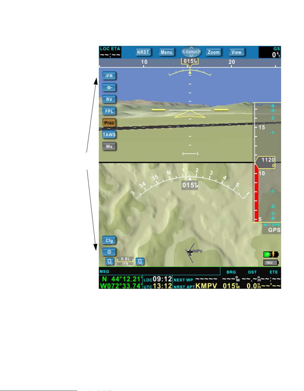
You can choose to view navigation information in 2D, 3D, or split-screen 2D/3D.
Split Screen 2D/3D
The split 2D/3D view displays the 3D view at the top of the screen, and the 2D
view at the bottom of the screen.
In this view, the up and down buttons of the arrow keypad change the zoom in
the 2D part only. The center button enters the 2D view in the Pan mode.
26 AV8OR 3D User Guide
Page 38

DRAFT
In Flight
Displaying the 2D View
The 2D view provides a top-down view of the terrain and course of the aircraft,
similar to a moving map display. The current filter view (VFR1/VFR2/IFR/App)
will dictate whether the ground and navigation features such as obstacles,
waypoints, and airspaces are displayed. You can configure these views using the
“Display Filters” on page 63.
AV8OR 3D User Guide 27
Page 39

In Flight
DRAFT
Track Target
Track Indicator
VOR
Airport
Lighted
Obstacle
NDB
Flight Plan
Scale
The course can be displayed by a track line. The length of the track line can be
specified in the Display tab on the Setup dialog.
An active flight plan or an instrument procedure is shown as a magenta line.
The 2D view can be oriented with the track of the aircraft pointing up, or with
north pointing up. You can select this in the Setup dialog under “Map orientation” described in “Display Settings” on page 54.
28 AV8OR 3D User Guide
Page 40

DRAFT
Zooming and Panning in the 2D View
AV8OR 3D provides the ability to zoom in/out on the 2D view in order to see
close-in detail, or to get a larger image of the general flight area. There are two
ways to zoom in/out when in either the Full 2D or Split 2D/3D view.
• Using the top menu, the Pan/Zoom button toggles the main display between
Pan and Zoom modes. The status of the mode is displayed in the center of the
arrow keypad icon in the top menu. When in the zoom mode, the up and
down arrows can be used to zoom in/out, while the left and right arrows can
be used for controlling the brightness of the display.
• In addition to the top menu, zooming in/out of the 2D display can be accom-
plished by pressing the (-) and (+) buttons to the left and right of the scale
indicator at the bottom left of the 2D window.
In order to switch to PAN mode, press the PAN button in the top menu. The
center of the arrow keypad icon in the top menu will switch to read Pan. You can
now use the arrow keys to pan up, down, left, and right of your aircraft position,
or around airport diagrams or approach charts.
Heading Indicator in 2D View
The heading indicator is displayed as a graduated arc. A white arrow indicates
the current magnetic track, and the numerical value is displayed in degrees just
below.
In Flight
The aircraft's heading in AV8OR 3D is based on GPS tracking, not on the absolute
heading of the aircraft, so there may be a variance between the AV8OR 3D heading
indicator and the aircraft's compass or directional gyro (DG). The aircraft
compass or DG should always be used as the primary instruments to determine
actual aircraft heading and crosswind effects.
When a flight plan or an instrument procedure is activated, a target course
(magenta a
not in the range of the track indicator, a magenta arrow shows the direction of the
bearing.
rrow) indicate
s the bearing to the next waypoint. When this bearing is
Track Line
The track line shows where the aircraft is expected to be after flying a specified
distance or a specified time. Its length and its visibility can be specified in “Track
line” in the Display tab described in “Display Settings” on page 54.
AV8OR 3D User Guide 29
Page 41

In Flight
DRAFT
There are three display options:
• Track line is hidden.
• Track line is straight, showing the actual heading of the aircraft.
• Track line is curved, displaying the predicted trajectory of the aircraft.
You can specify the length of the line in minutes of flight, nautical miles, or inches
on the tablet PC screen.
Aeronautical Information
Depending on your filter choices in the Setup dialog (Display Filter tab), and the
scale of the 2D view, different types of aeronautical information will be displayed.
The following kinds of items may be displayed in the 2D view:
Non lighted obstacle
(with altitude AGL)
Lighted obstacle (with
altitude AGL)
Airport (small scale
display)
Airport with runways
and Flight Rule Indicator
(large scale display)
VOR
NDB
VFR
Waypoint
Intersection
If you have the live weather option and a METAR data is available for an airport,
a Flight Rule Indicator is displayed under the name of this airport.
30 AV8OR 3D User Guide
Page 42

DRAFT
Airspace
Airspace boundaries are shown as thick lines. Terminal airspaces boundaries are
shown in blue, MOA in magenta, and special use airspaces in orange.
When the aircraft is either close to the airspace, or inside the airspace, the interior
of the airspace is shaded. Proximity of the aircraft to the airspace is considered
“close” based on the same parameter that is set for terrain awareness.
An airspace is considered “close” to the aircraft when:
• The airspace is in front of the aircraft and less than 10 nautical miles away,
and is at the same altitude or within the range + or - the terrain awareness
setting.
or
• The airspace is above or below the aircraft within the terrain awareness
setting.
The following kinds of airspaces are displayed:
In Flight
Bravo airspace
Charlie airspace
Delta airspace
Military operation area (MOA)
AV8OR 3D User Guide 31
Page 43

In Flight
Retrieving Additional Information in the 2D View
Summary and detail information about objects in the 2D view such as Controlled
Airspaces, Airports and VORs may be obtained by pressing the object. This will
bring up a summary information window next to the object. If more information
is desired, pressing the open summary window will open the Information screen
for the selected object.
Checking the Weather
DRAFT
Special use airspace
Temporary Flight Restriction (TFR)
To check the weather during flight:
1. Press the Menu button
2. Select the Wx button
3. Select the weather option that you would like to view
(Srfc/Icing/Wind/Text/None)
Surface Weather (SFC)
Depending on your level of XM weather subscription, surface weather will
include NEXRAD Radar, METAR Symbols, Fronts, Lightning, TFRs and Echo
Tops.
NEXRAD Radar shows the precipitation in different colors depending on the
intensity and the type of the precipitation and the echo tops indicating the highest
altitude at which precipitation is falling. This function displays the last image
received by the XM weather receiver. When this function is activated, the Wx
menu icon indicates the age of the currently displayed image. It is possible to
cycle on the three last images received by checking the animated weather option
in “Weather” on page 62. This tab also provides the legend for the NEXRAD and
Echo tops image.
32 AV8OR 3D User Guide
Page 44

DRAFT
Observed lightning is depicted on the 2D map by a small lightning bolt symbol at
each strike location.
In Flight
Freezing/Icing levels (Icing)
Freezing levels are depicted using an area color chart. A legend of colors representing freezing altitudes is provided at the bottom of the 2D display when this
function is selected. The levels depicted in the legend will change depending on
the current altitude of the aircraft.
Winds Aloft (Wind)
The winds aloft feature displays wind 'barbs' depicting the wind direction and
observed velocity. These symbols are displayed in accordance with standard FAA
symbology where the wind direction shows from the velocity marks towards the
tip of the wind barb. A legend of symbols is provided at the bottom of the 2D
display when this function is selected.
AV8OR 3D User Guide 33
Page 45

In Flight
DRAFT
The altitude for winds aloft is show at the bottom of the legend window and may
be varied by pressing the “+” and “-” buttons to the right of the Wx menu. Due to
the nature of winds aloft data, you may need to zoom out on the 2D window to
get an accurate picture of winds in the vicinity.
Weather data cannot be displayed unless it has been received from the satellite
service. The status of this data can be determined by reviewing the age of the
latest data at the bottom of the legend window for each weather function.
There may be a slight pause during the initial loading of weather data, such as
winds aloft, when the feature is selected for the first time.
Text Weather (Text)
Selecting the Text button will bring up a list of all airports currently reporting
METAR and/or TAF data, sorted by distance to your current location. Highlighting an airport in the list will display the METAR/TAF text at the bottom of
the window. Additional information, such as general airport information (altitude, runways, communication frequencies, etc.), as well as approach plates and
airport diagrams can be accessed from this page by selecting the appropriate
option from the right-hand menu.
Text weather may also be obtained directly from the 2D display. Simply press an
airport icon to display the airport summary information. Then, press the
34 AV8OR 3D User Guide
Page 46

DRAFT
summary pop-up window to display detailed airport information. If weather
information is available for this airport, the Wx button will allow you to display
the weather at the airport.
The airport must display a diamond indicating that current weather is available.
Removing Weather Data From the 2D Display
In order to remove all weather data from the 2D display, Select “Wx” from the
Menu, followed by “None”.
Displaying the 3D View
The 3D view is a synthesized view based on aircraft position and attitude. It is a
representation of the cockpit view with additional flight information displayed.
Objects in the 3D view, such as VORs, Airports and Intersections, are identified
with a “flag” noting the identifier of the object. In the case of airports and VORs,
navigation information is also displayed. VOR flags include the VOR name, the
radial that the aircraft is on, and the distance between the aircraft and the VOR is
displayed. Weather data is also displayed on airport flags in the form of METAR
“diamonds”, indicating the METAR conditions at the airport based on the color of
the diamond. See “Starting the Weather Service” on page 19 for more
information.
In Flight
AV8OR 3D User Guide 35
Page 47

In Flight
DRAFT
Track
Indicator
Bank
Indicator
Predictor
Pitch
Indicator
Airport
Intersection
If a flight plan or an instrument procedure is activated, a highway in the sky
(HITS) is shown in magenta.
Track Indicator in 3D View
The track indicator is a band at the top of the 3D view. A yellow arrow represents
the value of the magnetic track, and contains the numerical value in degrees.
When a flight plan or an instrument procedure is activated, a target course
(magenta bug) indicates the bearing to the next waypoint. When this bearing is
not in the range of the track indicator, a magenta arrow shows the direction of the
bearing.
36 AV8OR 3D User Guide
Page 48

DRAFT
Artificial Horizon
The artificial horizon display is a consolidation of the bank indicator and the pitch
indicator. Each graduation on the bank indicator represents 10 degrees.
The pitch indicator has graduations at every degree between +5 and -5 degrees,
and a graduation at +10 and -10 degrees as well.
When in straight and level flight, the central line of the pitch indicator is with the
two yellow lines.
The artificial horizon can also be overlaid in the 2D moving map mode by
enabling “Horizon on moving map” in the Display tab of the Setup dialog.
Predictor
The predictor is a small circle and gives you a prediction of the future position of
the plane in 9 seconds. It is computed using the current position, speed, rate of
turn, and rate of climb of the aircraft.
Highway in the Sky (HITS)
Navigation guidance is displayed in the 3D view with a highway in the sky
(HITS) representation. This shows the track to follow. The different waypoints
that compose the flight path are displayed as doors on the HITS.
In Flight
A moving square is positioned on the HITS 9 seconds ahead the aircraft. Correction of the aircraft course will cause changes in the position of the predictor.
Placing the predictor in the center of this square helps you stay on the course of
the flight plan.
When a flight plan is activated, the HITS changes its altitude according to the altitude of the aircraft: it is located at the closest even five hundred feet from the
aircraft altitude.
AV8OR 3D User Guide 37
Page 49

In Flight
Terrain Awareness (TAWS)
The Terrain awareness function changes the color of the terrain according to the
ground distance at the current altitude of the aircraft. Green terrain coloring
means the aircraft is more than the set altitude above the terrain, yellow that the
aircraft is above the terrain, but not more than the preset alert altitude, and red
the aircraft is below the terrain.
To activate terrain awareness:
DRAFT
1. Press Menu to display the menu options.
2. Press the TAWS button.
The alert altitude at which the terrain turns yellow can be set in the Display tab of
the Setup dialog.
When the Terrain Awareness function is turned on, the TAWS button is
displayed, even if the menu is hidden.
In the 2D view, the Terrain awareness function is disabled when the view is
zoomed out (scale > 5 nautical miles).
Terrain awareness is also not available when viewing icing levels.
38 AV8OR 3D User Guide
Page 50

DRAFT
Navigating
AV8OR 3D has four navigation modes:
• Direct To
• Radar Vectors
• Flight Plan
• Procedures
Creating a Direct To
The Direct To function is helpful for building a quick flight plan from the current
location to a specific point. It can also be used to amend a flight plan.
To Create a Direct To with a Flight Plan:
1. When a flight plan (or an instrument procedure) is activated, select the type
FPL.
This is useful for making a shortcut in a flight plan. In this case, the list
contains the waypoints of the flight plan.
Navigating
AV8OR 3D User Guide 39
Page 51

Navigating
DRAFT
2. Select one of these waypoints, and press the Direct To button to make the
flight plan act as if the next waypoint is the one selected.
Creating a Direct To with an Airport Type
When the airport type is selected, the central table displays a list of airports,
including for each one its name, its bearing and its distance from the aircraft position, its elevation, and the longest runway length.
The bottom part of the dialog displays the name of the airport, its exact location,
basic information about the runways, and the most useful frequencies in use a
this airport.
40 AV8OR 3D User Guide
t
Page 52

DRAFT
Highlight the Direct To menu item and press ENTER to build and activate a direct
flight plan from the current location of the aircraft to the highlighted airport.
The Info button displays a page containing detailed information about the airport
runways and frequencies, as well as additional remarks.
Some airports have a detailed diagram and/or approach plates. In this case, the
Plates button will become active and you can press it to display a list of available
plates for viewing.
If you have the live weather option (see “Starting the Weather Service” on
page 19), some airports will have weather information which you can access by
pressing the Wx button on the right side of the dialog. This displays a decoded
version of the last received METAR and TAF for the selected airport.
Entering an Airport Code
You can search for an airport by directly entering its code in the input field.
To enter the code with the buttons:
1. Highlight the input field
2. Press the ENTER button.
Navigating
The up/down arrows change the current letter, and the right/left arrows go
to the next/previous character.
3. When the selection is complete, press ENTER to validate the choice.
The “<“ button may be used at any time to clear the data entry field.
To enter the code with the tablet PC stylus:
1. Tap on the input field to display the virtual keyboard.
2. Select the order of the keys on the keyboard.
– QWERTY (regular computer keyboard arrangement)
– ABCD (alphabetically arranged).
AV8OR 3D User Guide 41
Page 53

Navigating
DRAFT
Direct To with a VOR, an NDB, or an Intersection Type
The application of the Direct To function with a VOR, an NDB, or an intersection
is similar to the application of Direct To for airports. The differences are:
• The bottom of the screen displays only the name and the location of the
object.
• The list contains only the name, bearing and distance (plus the frequency of
the VORs).
• The Info and View items are not selectable.
Direct To with a Weather Station Type (Wx)
If you have the live weather option, the Wx type will be available. If you select
this type, the central table displays only the airports for which weather data is
available. In this case, the bottom part of the dialog displays the METAR and the
TAF report.
42 AV8OR 3D User Guide
Page 54

DRAFT
Navigating
AV8OR 3D User Guide 43
Page 55

Navigating
Radar Vectors
DRAFT
The Radar Vectors function allows you to navigate by specifying heading and
altitude vectors. This is useful when following Radar Vector instructions from Air
Traffic Control (ATC).
To use the Radar Vectors function, select RV from the Main menu. Any currently
active navigation, such as a Direct-To or Flight Plan, will be deactivated and
placed “on hold.” In the upper-right of the navigation screen, you will see the
current heading and altitude in magenta. The Highway in The Sky (HITS) will
provide guidance for the entered heading and altitude.
44 AV8OR 3D User Guide
Page 56

DRAFT
The selected heading can be easily altered by pressing the (-) and (+) magenta
buttons found to the right and left of the top heading indicator. Similarly, the
selected altitude can be easily altered by pressing the (-) and (+) magenta buttons
found at the top and bottom of the altitude tape. Magenta “bugs” will appear
along both indicators marking the selected heading and altitude.
When Radar Vectoring is completed and you wish to continue your previous
navigation, simply press the RV button and AV8OR 3D will resume guidance to
your previous destination from your new current position.
Amending Your Flight Plan
To amend an existing flight plan:
1. Select Menu to display the Menu buttons on the main screen.
2. Select FPL to display the Flight Plan screen.
3. Highlight the flight plan you want to edit.
4. Press the Edit button.
Navigating
AV8OR 3D User Guide 45
Page 57

Navigating
DRAFT
Choose from the following:
Inserts a new destination or waypoint in the flight plan.
The default edit line appears at the end of the flight
plan. If you select an existing line in the flight plan and
tap Insert, the new line will appear above the highlighted line.
Deletes the highlighted airport or waypoint.
Scrolls up the list.
Scrolls down the list.
Reverses the course of your flight plan.
Activates the highlighted flight plan
Displaying the Nearest Object
To display the nearest airport or waypoint:
1. Press the NRST button on the tablet PC.
The Nearest function displays a list of the closest objects.
2. Select a Nearest type from the list on the left side of the screen.
The type can be selected to show information about the closest airports, intersections, VORs, or NDBs.
46 AV8OR 3D User Guide
Page 58

DRAFT
Navigating
AV8OR 3D User Guide 47
Page 59

Navigating
DRAFT
Nearest with an Airport Type
If you choose an airport, the central table displays a list of airports, including its
name, bearing and distance from the aircraft position, elevation, and the longest
runway length.
The bottom part of the dialog displays the name of the airport, exact location,
basic information about the runways, and the most useful frequencies in use at
this airport.
Select the Info button to display a page containing detailed information about the
airport runways and frequencies, as well as remarks regarding the airport.
Some airports have a detailed diagram. In this case, the View button activates and
you can press it to display this diagram.
If you have the live weather option, some airports will have weather information
which you can access by pressing the Wx button on the right side of the dialog.
This displays a decoded version of the last received METAR and TAF for the
selected airport.
Nearest with a Weather Station Type (Wx)
If you have the live weather option, the Wx type will be available.
Select Wx to display only the airports for which weather data is available. In this
case, the bottom part of the dialog displays the METAR and the TAF report.
Activating Approach Procedures
While in flight, you can activate approach procedures for an airport. The Procedure function is useful for selecting an instrument procedure, displaying it on the
2D and 3D maps, and displaying its approach plate.
To activate a procedure:
1. Press the Menu button to display the menu options.
2. Press the Proc button.
The waypoints and airports in your flight plan are displayed.
3. Press to highlight the airport.
You now have the following choices:
48 AV8OR 3D User Guide
Page 60

DRAFT
Menu Item Description
Navigating
Plots a course directly to the selected airport.
When a procedure is highlighted, press the Activ
button to activate the procedure.
Allows you to search for an airport not currently listed
in your flight plan. You can search by airport code or
name. Tapping in the Code or Name fields displays a
Virtual Keyboard.
You can also select other waypoints from the Type
menu on the left side of the screen.
Displays the detailed airport information.
Displays the current plates for the airport. The airport
diagram screen also provides three button allowing
you to zoom in, zoom out and rotate the airport
diagram. Closing this window will return to the main
navigation screen. In order to return to the list of plates,
select Plates from the right-hand menu.
Displays the current weather at the airport.
Course Deviation Indicator
The course deviation indicator (CDI) is only displayed when an instrument procedure or a flight plan is activated.
AV8OR 3D User Guide 49
Page 61

Shutting Down AV8OR 3D
DRAFT
Caution: When an instrument procedure is activated, a full deviation of the
CDI represents 2.5º.
Shutting Down AV8OR 3D
To shut down AV8OR 3D:
1. Exit the AV8OR 3D program
Press the Menu button and select the Exit button in the lower left portion of
the screen. You will be given the choice of shutting down the tablet PC (Turn
off), going back to Windows (Windows), or returning to AV8OR 3D (Cancel).
2. Power off the INU
3. Power off the tablet PC
Using the Simulator Mode
AV8OR 3D offers a simulation mode which is useful for helping you learn about
AV8OR 3D features.
To enter simulation mode
1. Start the tablet PC for navigation mode without powering on the INU.
2. Select Simulator from the menu and press the center arrow key or press the
screen button.
50 AV8OR 3D User Guide
Page 62
DRAFT
Using the Simulator Mode
To change the default start-up airport:
1. Press the Menu button to display the menu.
2. Select the Cfg button to display the Setup dialog.
3. Select the INU/Simu tab
4. Click on the “Position at” field.
A virtual keyboard will display allowing you to select an airport using a
4-letter ICAO station identifier.
AV8OR 3D User Guide 51
Page 63

Using the Simulator Mode
DRAFT
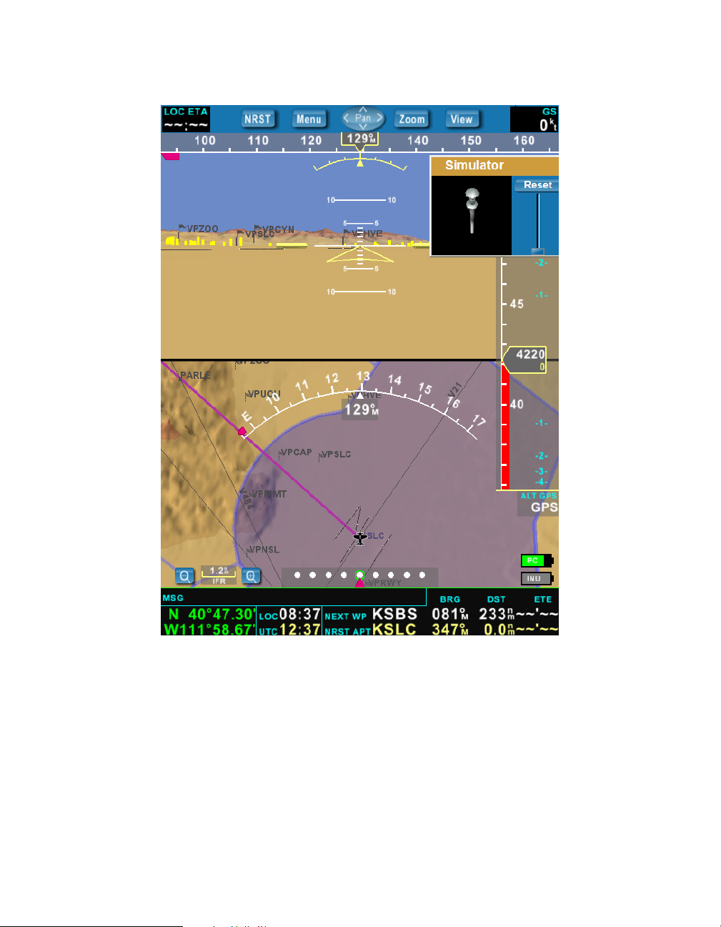
To control the aircraft:
1. In the Simulator pop-up window, use the stylus to move the “Control Stick”
icon and simulate the aircraft attitude: turn, descend and climb.
Note: Touching the “Control Stick” closer to bottom of the stick provides smaller,
graduated movements. At any time, you can level the aircraft by pressing the
Reset button at the top of the simulator pop-up window.
2. To control the aircraft speed, use the stylus to move the slide bar up and
down.
You can also control the overall simulation speed by setting the “Simulation
rate” on the INU/Simu tab in the Setup dialog.
You can reset the simulation by using the stylus to touch the Reset button.
To stop the simulation:
1. Press the Menu button to display the Menu.
2. Select the Cfg button to display the Setup dialog.
3. Press the Stop button in the Simulation area.
52 AV8OR 3D User Guide
Page 64

User Guide:
Chapter 4 Configuring Your VistaNav
Version 4.4 Size: 7 x 9 Mode: Printing 5/23/06
DRAFT – FOR REVIEW ONLY
4
Configuring Your AV8OR 3D
Configuration Settings
Use the information in the following sections to customize your AV8OR 3D.
To access the Setup screen, press the Menu button and then the Cfg button on
the Menu.
To view all available tabs in the Setup screen, press the arrow buttons to scroll
left or right through the Setup tabs.
To close the Setup screen, press the Close button
AV8OR 3D User Guide 53
Page 65

Configuration Settings
Display Settings
Press the Display tab to view the following settings.
DRAFT
The Display tab allows you to set the following:
Menu Choice Available Settings
Light mode Day or night
Map orientation (2D) Track or North
Horizon on moving map On if you want to see the artificial
horizon displayed on the 2D moving
map view.
54 AV8OR 3D User Guide
Page 66

DRAFT
Menu Choice Available Settings
Track line graphic (2D) No track line, straight, curved.
Track line measurement Minutes, Nautical miles, or inches
Menu always visible Check to always display the Menu on
Show expired TFRs Check to display all expired TFRs in
Only next 3 hours TFRs Check to display all TFRs that will be
Show NFL TFRs On to display displays all TFRs around
Terrain awareness Measurement in feet (default is 500 ft.).
Default Press to reset all Display settings to
Configuration Settings
the left side of your screen.
addition to the one that are already
displayed.
active in 3 hours in addition to the one
that are already displayed.
NFL football stadium in addition to
the one that are already displayed.
factory default.
AV8OR 3D User Guide 55
Page 67

Configuration Settings
Time and Date
Press the Time & Date tab to view the time and date of your location. AV8OR 3D
obtains the time from the GPS.
DRAFT
56 AV8OR 3D User Guide
Page 68

DRAFT
INU and Simulator
Press the INU/Simu tab to view the following INU and Simulator settings.
Configuration Settings
AV8OR 3D User Guide 57
Page 69

Configuration Settings
INU Settings
Menu Choice Available Settings
Altimeter mode Barometric or GPS altitude
Barometric settings Used to calibrate the display with the baro-
Adjustment If the INU is not set perfectly flat in the aircraft,
Reset connection Resets the connection between the INU and the
DRAFT
metric sensor in the INU.
In the Barometric Settings field, press the
display to highlight the barometric number.
Use the rocker button on the top of the tablet
PC to adjust the barometric setting up or
down.
you can specify the pitch and bank angles by
tapping to highlight the field and using the
rocker button on the top of the tablet PC to
adjust the setting up or down.
tablet PC.
Simulation Settings
Menu Choice Available Settings
Start / Stop Starts or stops a simulation flight
Position at Set the current position of your aircraft in the
the simulation. To change:
1) Tap in the field to display the Virtual
Keyboard.
2) Enter the position code and press ENTER.
Simulation rate Tap in the field to enter a faster rate and speed
travel between waypoints.
58 AV8OR 3D User Guide
Page 70

DRAFT
GPS
Press the GPS tab to view the current satellite count and strength of signals.
Configuration Settings
The GPS tab provides a visual reference of satellite acquisition status. The signal
bars give the strength of the signal for each satellite in view. The sky view shows
the location of each satellite relative to the receiver's last known position.
The INU requires the tracking of at least three satellite signals.
AV8OR 3D User Guide 59
Page 71

Configuration Settings
Power
Press the Power tab to display the power status of both the LS800 tablet PC and
the INU-75GB.
DRAFT
60 AV8OR 3D User Guide
Page 72

DRAFT
XM Information
Press the XM Info tab to display XM receiver information.
Configuration Settings
This tab is used to activate the XM Satellite receiver unit. It also provides information about the connection between the tablet PC and this receiver, your receiver
serial number, the type of service you subscribe from XM, and the quality of the
signal (low values of BER indicate a good reception). The table on the bottom
right of the dialog displays a list of received products and the elapse time since
the last transmission.
AV8OR 3D User Guide 61
Page 73

Configuration Settings
The XM weather service products displayed are:
• METAR
• TAF
• TFR
• High Resolution NEXRAD Radar
• Precipitation Type (at surface)
• Satellite Mosaic
Weather
Press the Weather tab to display the NEXRAD (Radar, Precipitation) and Clouds
Tops (Satellite Mosaic) legend. The checkbox allows you to deactivate the weather
animation.
DRAFT
62 AV8OR 3D User Guide
Page 74

DRAFT
Display Filters
You can modify the features that you want to see on the display for the 2D and 3D
views.
On each view you have up to 4 display filter configurations that you can set up
the way you want.
You can cycle through these 4 configurations by pressing the
VFR1/VFR2/IFR/App button.
Configuration Settings
AV8OR 3D User Guide 63
Page 75

Configuration Settings
Log Flights
AV8OR 3D logs flight information for every flight using the INU.
Each time you start a flight, AV8OR 3D detects your departure airport and your
arrival airport. AV8OR 3D logs the airports, the duration of the flight, and the date
of the flight in the Log Flights tab.
DRAFT
64 AV8OR 3D User Guide
Page 76

User Guide:
Appendix A Safety, License Agreement, Warranty, and Technical Support
Version 4.4 Size: 7 x 9 Mode: Printing 5/23/06
DRAFT – FOR REVIEW ONLY
A
Safety, License Agreement, Warranty, and Technical Support
Important Safety Precautions and Environmental
Specifications
Electrical Safety
This product is intended for use when supplied with power from a cigarette
lighter power supply (12V) or the internal battery.
Battery
This product contains a NiMH custom battery pack. This battery pack is to be
replaced only by an approved Honeywell facility. Any attempt to change the
battery yourself, or to open the case of the INU will void the warranty of the unit.
Pollution Degree Category
This product is categorized as Pollution Degree - II and Over Voltage
Category - II.
Other Required Disclosures and Compliances
This device complies with Part 15 of the FCC Rules. Operation is subject to the
following two conditions,
1.This device may not cause harmful interference and
2.This device must accept any interference received, including interference that
may cause undesired operation.
CSA Approval
This product is for indoor use only.
AV8OR 3D User Guide 67
Page 77

AV8OR 3D User’s Guide
HONEYWELL CUSTOMER SUPPORT
For more information, including details regarding your warranty,
visit www.Bendixking.com
:For technical support of this product please contact your local
Bendix/King Dealer. To locate the Bendix/King Dealer nearest you
visit www.Bendixking.com.
For additional support contact Honeywell Customer & Product
Support: at:
US/Canada: 800-601-3099
International: 602-365-3099
Fax: 602-365-3343
.
.
© Honeywell International Inc. Do not copy without express permission of
Honeywell.
Page 78

AV8OR 3D User’s Guide
Honeywell Aerospace Technical Publications
If you have access to the Internet, go to the Honeywell Online
Technical Publications Web site at
https://portal.honeywell.com/wps/portal/aero
• Download or see publications online
• Make an order for a publication
• Tell Honeywell of a possible data error in a publication.
If you do not have access to the Honeywell Online Technical
Publications web site and need technical publications information:
• Send an e-mail message to the complete customer care
center at:
cas-publications-distribution@honeywell.com
• Send a fax or speak to a person at the complete customer
care center contact numbers.
to:
.
© Honeywell International Inc. Do not copy without express permission of
Honeywell.
 Loading...