

Page 1
Operating instructions for
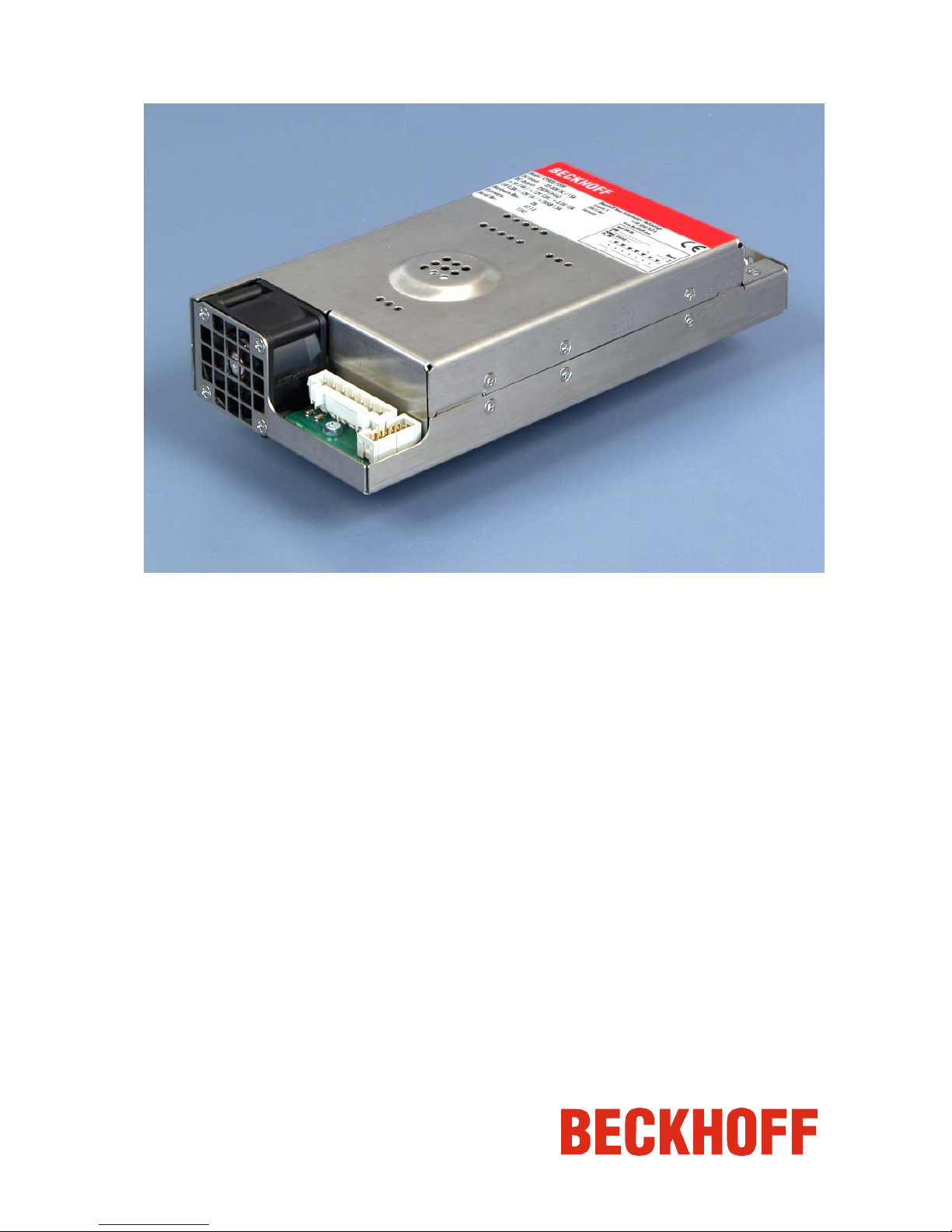
C9900-P209 power supply unit
Version: 1.1
Date: 2006-01-26
Page 2

Page 3

Table of contents
Table of contents
1.
2.
3.
4.
5.
6.
General Notes 2
Notes on the documentation 2
Liability Conditions 2
Description of safety symbols 2
Basic safety measures 3
Operator's obligation to exercise diligence 3
Product Description 4
Appropriate Use 4
Electrical data 4
Configuration and installation 4
Connecting the power supply unit 5
Connection with the motherboard 5
Pin assignment of the pin strips 5
Connection with the Industrial PC 6
Preparing the cable harness 6
External wiring 7
Power supply of the Industrial PC 7
On/Off switch 7
Wiring 7
Installation of the supply cables 8
Connector installation 8
Cable cross-sections 8
UPS software components 9
Installation on the PC 9
Software configuration 9
Help files 9
Servicing 9
Shutting down 9
Disposal 9
Troubleshooting 10
Service and Support 10
Beckhoff Service 10
Beckhoff Support 10
Company headquarters 10
Assembly dimensions 11
Wiring diagram 12
Appendix 13
Technical data 13
Approvals 13
FCC: Federal Communications Commission 13
Radio Frequency Interference Statement 13
FCC: Canadian Notice 13
C9900-P209 1
Page 4
General Notes
General Notes
Notes on the documentation
This description is only intended for the use of trained specialists in control
and automation engineering who are familiar with the applicable national
standards. It is essential that the following notes and explanations are
followed when installing and commissioning these components.
Liability Conditions
The responsible staff must ensure that the application or use of the
products described satisfy all the requirements for safety, including all the
relevant laws, regulations, guidelines and standards.
The documentation has been prepared with care. The products described
are, however, constantly under development. For this reason, the
documentation may not always be have been fully checked for consistency
with the performance data, standards or other characteristics described.
None of the statements in this manual represent a guarantee for as set out
in § 443 of the German Civil Code or a statement about the assumed use
according to the contract as set out in § 434 para. 1 clause 1 no. 1 of the
German Civil Code. In the event that it contains technical or editorial errors,
we retain the right to make alterations at any time and without warning. No
claims for the modification of products that have already been supplied
may be made on the basis of the data, diagrams and descriptions in this
documentation.
© This documentation is protected by copyright. Any reproduction or third
party use of this publication, whether in whole or in part, without the written
permission of Beckhoff Automation GmbH, is forbidden.
Description of safety symbols
The following safety symbols are used in this operating manual. They are
intended to alert the reader to the associated safety instructions.
Danger
This symbol is intended to highlight risks for the life or health of personnel.
Warning
This symbol is intended to highlight risks for equipment, materials or the
environment.
i
Note
This symbol indicates information that contributes to better understanding.
2 C9900-P209
Page 5
Basic safety measures
i
Note
The power supply unit must only be used in conjunction with
Beckhoff Industrial PCs!
Warning
Switch off the power supply of the system during installation!
During assembly, removal and electrical wiring of the power supply unit,
the power supply of the system must be switched off in order to prevent
damage on the power supply unit and the Industrial PC.
Items of equipment that have been switched off must be secured against
being switched on again.
Danger
Do not open the power supply unit while voltage is applied!
The supply voltage must be switched off before the power supply unit
housing is opened.
Operator's obligation to exercise diligence
Warning
Only appropriately trained staff may install the power supply unit!
The operator must ensure that only appropriately trained electricians deal
with installation and wiring of the power supply unit.
C9900-P209 3
Page 6

Product Description
Product Description
Appropriate Use
The C9900-P209 power supply unit provides the power supply for Beckhoff
Industrial PCs. An uninterruptible power supply (UPS) can be arranged in
conjunction with a C9900-U330 battery pack.
Danger
Risk of explosion if other battery packs are used!
Electrical data
Input voltage: 22-30V DC/ 15A
Power output: 250W (max.)
Output voltages: + 5V 14A
+ 12V 12A
+ 3.3V 12A
- 5V 0.3A
- 12V 0.5A
+ 5VSB 1.5A
Configuration and installation
C9900-P209 power supply
unit
The power supply unit is installed at the prescribed position in the Industrial
PC.
The supply connections for the power supply unit are located next to the
fan (1). The electrical connections for the motherboard are on the opposite
side (2).
2
1
4 C9900-P209
Page 7

Product Description
Connecting the power supply unit
Connection with the motherboard
Pin strips
on the output side
Connection Function
1
ATX interface
2
5V/12V supply
3
POWER ON
4
COM interface
Connection with the
motherboard
The power supply unit is connected
with the motherboard according to
the installation instructions of the
board.
5
12V supply
Pin assignment of the pin strips
Pin Function Pin Function
1
3.3V
11
3.3V
2
3.3V
12
- 12V
3
GND
13
GND
4
+ 5V
14
PS ON
5
GND
15
GND
6
+ 5V
16
GND
7
GND
17
GND
8
PWR OK
18
- 5V
9
5VSTB
19
+ 5V
10
12V
20
+ 5V
ATX DC output
Pin Function Pin Function
1
+ 12V
5
+ 12V
2
GND
6
GND
3
GND
7
GND
4
+ 5V
8
+ 5V
5V/ 12V supply for drives
Pin Function
1
POWER-ON
2
POWER-ON
POWER ON
Pin Function
3
TXD
5
RXD
9
GND
COM interface
(RS 232)
Pin Function Pin Function
1
GND
3
+ 12V
2
GND
4
+ 12V
ATX 12V DC-Output
1
2
3
4
5
C9900-P209 5
Page 8

Product Description
Connection with the Industrial PC
The 7-pin pin strip (1) with CAGE CLAMP connection shown on the
photograph is mounted on the power supply unit for connecting the unit
with the respective power supply connection sockets and the illuminated
toggle switch within the PC.
Connection Function
1
DC input
2
optional
Pin strips at the power
supply unit
Pin Function
1
Battery -
2
Battery +
3
PE
4
GND
5
Input +24V
6
Power-Status
Pin assignment of the pin
strip
7
PC_ON
Preparing the cable harness
A cable harness is used for connecting the power supply unit with the
connection sockets in the Industrial PC. Due to different cable lengths, the
harness is produced individually for each type of computer.
The wiring diagram section shows the connection between the 7-pin power
supply unit connector and the 3-pin and 5-pin pin strip at the PC case:
Cable harness wiring
diagram
Warning
Insert fuse!
The power supply for the illuminated toggle switch must be protected with a
fuse! To this end, a "flying" fuse (6.3A/ medium time-lag) is inserted in the
line.
Note cable cross sections
The cable cross sections are 0.75 mm
2
/ AWG18 for connecting the
illuminated toggle switch and 2.5 mm2 / AWG14 (screened) for connecting
the power supply.
2
1
7
6 5 4
1
2
3
6 C9900-P209
Page 9

Product Description
External wiring
The external wiring consists of the connection of the power supply and the
battery pack with the Industrial PC and the connection with an illuminated
toggle switch in the control cabinet enclosure for switching the PC on and
off.
Power supply of the Industrial PC
The 5-pin pin strip with CAGE CLAMP connection and mounting flanges
shown on the photograph is mounted on the PC case for connecting the
power supply and the battery pack.
Pin Function
1
Power supply +24 V
2
Power supply GND
3
Protective conductor
4
Battery pack +24 V
5
Battery pack GND
Pin assignment for
connecting power supply
and battery pack
On/Off switch
The Industrial PC is switched on and off with an illuminated toggle switch.
To this end, a 3-pin pin strip with CAGE CLAMP connection and mounting
flanges is installed at the PC case.
Pin assignment for
connecting the on/off switch
Pin Function
1
Power-Status
2
PC_ON
3
+ 24 V
Wiring
Wiring according to the wiring diagram:
Wiring diagram for external
components
1
2
3
4
5
3
2
1
C9900-P209 7
Page 10

Product Description
Installation of the supply cables
Wiring according to the
wiring diagram
Install the cables for the power supply of the Industrial PC, the connection
of the battery pack and the connection of the illuminated toggle switch
according to the wiring diagram using the connector assembly material
provided.
Connector assembly is described using the example of the 5-pole female
plug connector:
Materials for assembly of
the connector
Female plug connector, 5-pole
Strain relief housing
A
B
C
D
Connector installation
Fitting the connector to the
cable
The plug is fitted to the cable as follows:
1. Remove the insulation from the cable ends (8 - 9 mm).
2. Push the cable into the holders, applying slight pressure according
to the pin assignment label and the wiring diagram.
3. Push the lower part (part A) of the strain relief housing onto the top
of the female plug connector until it snaps into place.
4. Relieve the strain on the supply cable by fixing it in place with the
cable clamp (part C) and fixing screws (part D) (see photograph
below).
Applying the strain relief
Fix the upper part (part B) of the strain relief housing by snapping it onto
the lower part.
Cable cross-sections
Avoid voltage drop
Use cables with a cross-section of 2.5 mm
2
(AWG 14) for the supply lines
to the Industrial PC. The distance between power supply and PC should
not exceed 10 m in order to avoid excessive voltage drop in the cable.
8 C9900-P209
Page 11

Product Description
UPS software components
Installing the UPS driver
software
For operating the power supply unit as a UPS, the UPS driver software and
the associated UPS driver must be installed on the Industrial PC.
On delivery of the Beckhoff Industrial PC with operating system the
software is already installed. Should the software not be installed on your
PC, the drivers can be installed from the driver CD provided.
Installation on the PC
Installation
To install the UPS driver software, execute file
Beckhoff_UPS_Versionxxx.exe from the CD provided on the Industrial
PC (Start > Run > Program). The program is self-extracting and will guide
the user through the installation routine.
Software configuration
Configuration
The UPS driver software is configured in the operating system control
panel.
After successful installation of the software, an additional "Beckhoff UPS
configuration" tab will appear under Start > Settings > Control Panel >
Power Options. This is used for configuring the device (setting of the
battery parameters), configuring the alarm parameters, and for reading the
current battery parameters such as state of charge and remaining capacity.
Help files
Beckhoff information
system
The driver software comes with a detailed help function.
The help files can be called up either directly from the configuration register
by clicking the Help button, or under via Start > Programs > Beckhoff >
UPS software components.
Servicing
The power supply unit is maintenance-free.
Shutting down
Disposal
Dismantling the case
Observe national
electronics scrap
regulations
The device must be fully dismantled in order to dispose of it. The housing
can be sent for metal recycling.
Electronic parts must be disposed of in accordance with national
electronics scrap regulations.
C9900-P209 9
Page 12

Troubleshooting
Troubleshooting
In the event of a fault contact your Beckhoff Service.
Service and Support
Beckhoff and their partners around the world offer comprehensive service
and support, making available fast and competent assistance with all
questions related to Beckhoff products and system solutions.
Beckhoff Service
The Beckhoff Service Center supports you in all matters of after-sales
service:
• on-site service
• repair service
• spare parts service
• hotline service
Hotline:
+49(0)5246/963-460
Fax: +49(0)5246/963-479
e-mail: service@beckhoff.com
Beckhoff Support
Support offers you comprehensive technical assistance, helping you not
only with the application of individual Beckhoff products, but also with
other, wide-ranging services:
• world-wide support
• design, programming and commissioning of complex automation
systems
• and extensive training program for Beckhoff system components
Hotline:
+49(0)5246/963-157
Fax: +49(0)5246/963-9157
e -mail: support@beckhoff.com
Company headquarters
Beckhoff Automation GmbH
Eiserstr. 5
D-33415 Verl
Germany
Phone:
+49(0)5246/963-0
Fax: +49(0)5246/963-198
e-mail: info@beckhoff.com
The addresses of Beckhoff's branch offices and representatives round the
world can be found on the internet pages:
http://www.beckhoff.com
You will also find further documentation for Beckhoff components there.
10 C9900-P209
Page 13

Assembly dimensions
Assembly dimensions
Device dimensions and mounting points.
Dimensional notation in mm.
C9900-P209 11
Page 14

Wiring diagram
Wiring diagram
C9900-P209 power supply unit in conjunction with C9900-U330 battery
pack
12 C9900-P209
Page 15

Appendix
C9900-P209 13
Appendix
Technical data
Electrical data
Input voltage: 21-30V DC/ 16A
Power output: 250W (max.)
Output voltages: see section Product Description
Dimensions
Dimensions (W x H x D): 97.0 x 44.0 x 203.9 mm
Weight: 0.85 kg
Do not use the power
supply unit in areas of
explosive hazard
The power supply unit must not be used where there is a risk of
explosion.
The following conditions must be observed during operation:
Environmental conditions
Ambient temperature: 0 to 55°C
Atmospheric humidity: Maximum 95%, non-condensing
Shock resistance Sinusoidal vibration
(EN 60068-2-6):
10 to 58 Hz: 0.035 mm
58 to 500 Hz: 0.5 G (~ 5 m/ s2)
Impact
(EN 60068-2-27/ -29): 5 G (~ 50 m/ s²), duration: 30 ms
EMC compatibility
Resistance to interference: according to EN 61000-6-2
Emission of interference: according to EN 61000-6-4
Transport and storage
The same values for atmospheric humidity and shock resistance are to be
observed during transport and storage as in operation. The shock
resistance during transport can be improved by appropriate packaging of
the power supply unit. The ambient temperature during storage and
transport must be between -20°C and +65°C.
Approvals
FCC: Federal Communications Commission
Radio Frequency Interference Statement
FCC Approval for USA
This equipment has been tested and found to comply with the limits for a
Class A digital device, pursuant to Part 15 of the FCC Rules. These limits
are designed to provide reasonable protection against harmful interference
when the equipment is operated in a commercial environment. This
equipment generates, uses, and can radiate radio frequency energy and, if
not installed and used in accordance with the instruction manual, may
cause harmful interference to radio communications. Operation of this
equipment in a residential area is likely to cause harmful interference in
which case the user will be required to correct the interference at his own
expense.
FCC: Canadian Notice
FCC Approval for Canada
This equipment does not exceed the Class A limits for radiated emissions
as described in the Radio Interference Regulations of the Canadian
Department of Communications.
 Loading...