

Page 1

C1300 VME to II/O Interface Unit Beckhoff II/O-System
VME to II/O Interface Unit
Technical Documentation
Eiserstraße 5 phone: +49(0)5246/963-0
33415 Verl fax: +49(0)5246/963-149
Date : 18.12.95 Version : 2.01 Page 1 of 44
Page 2

C1300 VME to II/O Interface Unit Beckhoff II/O-System
Table of contents
1. System Description.............................................................................................5
1.1 The Beckhoff II/O System ...........................................................................5
2. Function Description Hardware.....................................................................10
3. Function Description Software.......................................................................11
3.1. About the Software ....................................................................................11
3.2. Description of the Handshake Channels ....................................................13
3.3. Test and Analysis Functions ......................................................................17
3.4. Configuration .............................................................................................27
3.4.1. CDL-Communication.......................................................................29
3.4.2. Free programmable Communication................................................32
3.4.3. Initialisation of "Fast Fiber Optic - Interrupts"................................36
3.5. Signal state control functions.....................................................................38
4. Technical Data..................................................................................................41
5. Installation........................................................................................................42
5.1. Configuration .............................................................................................42
Page 2 of 44 Version : 2.01 Date : 18.12.95
Page 3
C1300 VME to II/O Interface Unit Beckhoff II/O-System
Date : 18.12.95 Version : 2.01 Page 3 of 44
Page 4

C1300 VME to II/O Interface Unit Beckhoff II/O-System
...........................................................................................................................43
5.3. Installation on the VME Card Cage...........................................................44
Page 4 of 44 Version : 2.01 Date : 18.12.95
Page 5
C1300 VME to II/O Interface Unit Beckhoff II/O-System
1. System Description
1.1 The Beckhoff II/O System
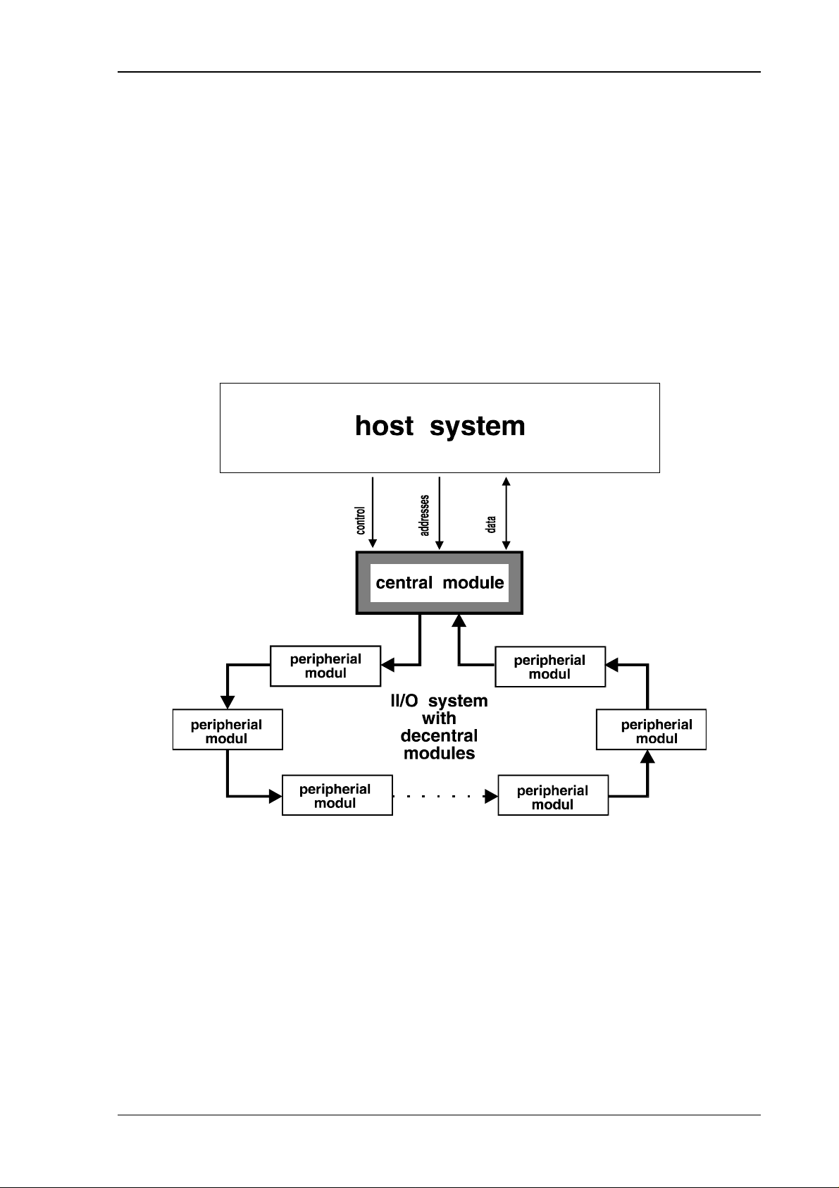
the Beckhoff Industrial Input Output System, which is abrevated II/O System, consists of a
smart central modul and a field bus that is based on fiber optics. Picture 1 shows an overview
of the II/O system.
picture.1
Date : 18.12.95 Version : 2.01 Page 5 of 44
Page 6

C1300 VME to II/O Interface Unit Beckhoff II/O-System
The connection of the II/O system to the host system is established by a DPRAM. This is
providing fast and comfortable communications.
The processing of the diverse signal states is supported by several II/O peripheral modules,
which are linked in a ring structure.The use of fiber optics minimizes the sensitivity for
interferences and allows a high transmission rate of 2.5 MBd. Errors, occuring in the FO-ring, will be detected and reported to the host system by the central module. Functions
implemented for ring diagnosis, enable quick detection and correction of errors.
There is a speed and simplicity optimized communications protocol which, in the further
course of this documentation, will be called a telegram.
Communications on the FO-ring are controlled by the central module. This module will send
telgrams, that pass each of the modules in the FO-ring and are eventually received and
checked.
Page 6 of 44 Version : 2.01 Date : 18.12.95
Page 7
C1300 VME to II/O Interface Unit Beckhoff II/O-System
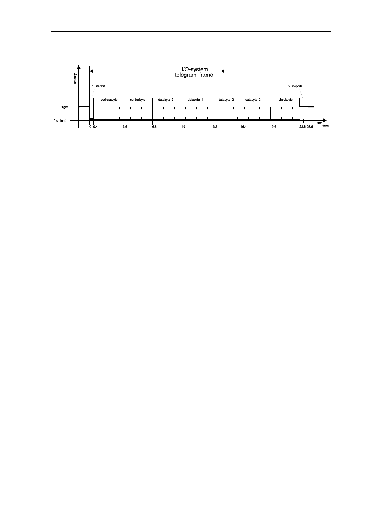
A telegram consists of a frame and the contents.
picture 2: Telegram structure of the II/O-System
The frame is needed for serial and asynchronous data communications. There is a single start
bit, 6 CRC check bits and 2 stop bits. The frame is created and checked by the hardware, so
that there is no need for additonal software support.
Date : 18.12.95 Version : 2.01 Page 7 of 44
Page 8

C1300 VME to II/O Interface Unit Beckhoff II/O-System
The contents of the telegram is mainly organized for each byte.
AD0 - AD7 create the address field.Using this address field up to 254 modules can be
addressed ( Address 00h and 0fh are reserved. ).
CR0 - CR3 define the type of telegram. Following functions can be defined in the telegram:
CR3 CR2 CR1 CR0 Function Beschreibung
0000
0001
0010
0100
1001
READ
READ/WRITE
ADDRESS INITIALIZITION
ADDRESS CHECK AND
COUNT COMMAND
LOW INT ENSITY
COMMAND
The modul addressed writes the entry data into
the Data fields D0 - D3 .
The modul addressed writes the entry data into
the Data fields D0 - D3 and loads the
Ausgangsinformation.
The module addressed loads the contents of D0
as a module address und sets D0 = 0.
Each module passed increases the contents of
D0 by 1. The module addressed is loads the
contents from D0 into D3.
The module addressed reduces the transmission
intensity by 20%.
picture 3:Controlfield
Byte D0 - D3 contain the actual Data to use. The processing of this data is determined by the
controll field.
The last Byte in a telegram contains two spare bits and 6 bits to create a CRC checksum. The
contents, having a length of 50 bits, achieves a Hamming distance of d = 3.
Page 8 of 44 Version : 2.01 Date : 18.12.95
Page 9

C1300 VME to II/O Interface Unit Beckhoff II/O-System
The Beckhoff II/O fieldbus consists of a physical ring, that can be split into 8 logical rings in
order to process the signal states. A logical ring can only be run on preselected modules,
which are defined by Communication Description Lists ( CDLs ) or freely programmable
comunications. Later in this text the way this definitions are transmitted will be delt with.
The host system is provided with the signal states via the DPRAM, which can be divided into
3 areas.
-Data : Input , output
-Communications : Initialization, test, analysis and configuration of the II/O-
Systems
-Process control : Refresh of signal states
The central module needs an area of 4 Kbyte in the address space of the host system.
Date : 18.12.95 Version : 2.01 Page 9 of 44
Page 10
C1300 VME to II/O Interface Unit Beckhoff II/O-System
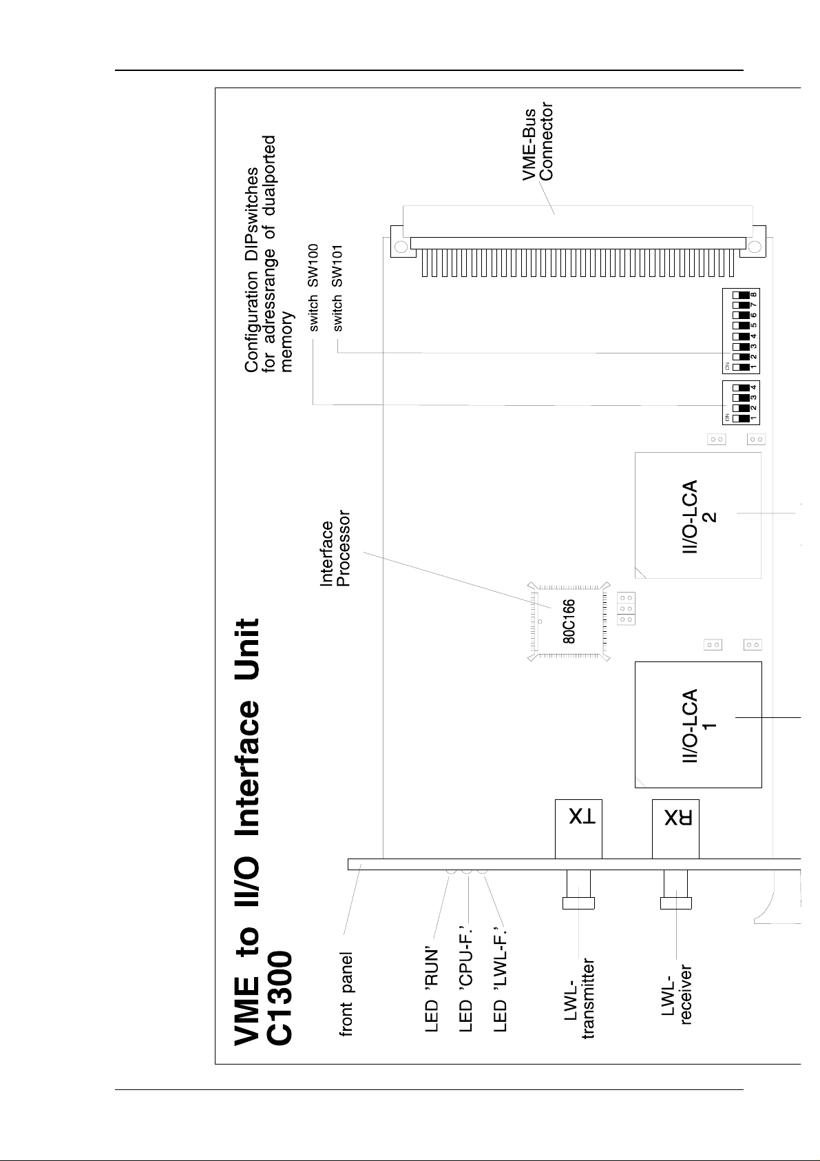
2. Function Description Hardware
C1300
The central module C1300 is a smart port for communications between the II/O-System and
the VMEbus. There is a 2k*8 dual ported SRAM for comunications between the II/O -System
and the VMEbus. It is addressed directly through the VMEbus. The VMEbus slave interface
has the following properties:
* AMO’s: Standart Supervisory Program Access
Standart Supervisory Data Access
Standart Non-Privileged Program Access
Standart Non-Privileged Data Access
* A24/D16 and A24/D08 - Slave according to VMEbus Rev.C1, no block-transfer
* D08 Interrupter according to VMEbus Rev.C1
Page 10 of 44 Version : 2.01 Date : 18.12.95
Page 11

C1300 VME to II/O Interface Unit Beckhoff II/O-System
3. Function Description Software
3.1. About the Software
Address space (hex) Funktion
000 - BFF Data area
(input, output )
3 kByte
C00 - CFF Handshake-channel 0 : VME -> C1300
(configuration, test, analysis)
D00 - DFF Handshake-channel 1 : C1300 -> VME
(configuration, test, analysis)
E00-FF9 reserved
FFA - FFF GCB (General Control Block)
(demand, ready und error mask)
Overview : Distribution of the port‘s workspace.
The port between VMEbus and C1300 module enables the following functions:
- Data exchange of signal states
- Test- und analysis functions for II/O-System
- Configuration
- Control of signal states
The II/O System can be configurated through the comunications channels by 4 functions. This
way the input and output lines are distributed to the addresses in the DPRAM. The
communications channels can also be used to reach nine more functions for t esting and analysi s .
The lower 2 Kbyte area, which is used by the C1300 module in the VME address space, is the
place for the data areas of the CDLs. The call to refresh the signal states is done by setting a
bit in the demand mask of the GCB ( General Control Block ). The ready message can be
taken from the predefined bit in the ready mask of the GCB.
Date : 18.12.95 Version : 2.01 Page 11 of 44
Page 12
C1300 VME to II/O Interface Unit Beckhoff II/O-System
Page 12 of 44 Version : 2.01 Date : 18.12.95
Page 13
C1300 VME to II/O Interface Unit Beckhoff II/O-System
3.2. Description of the Handshake Channels
Communications between VMEbus and C1300 are supported by two channels, which contain
255 bytes. The VME master writes the data, needed to run a certain function, to channel 0 and
then transmitts a DV ( data valid ) signal. When the module has received all of the data, it
will send the "Quit" signal. The VME master erases the DV signal and as soon as the "Quit"
signal is set to zero, new communications can be started.
Channel 0 leading from the VMEbus to the C1300 module has an address range from C01h to
CFFh. DV is the MSB of address C00h. "Quit" is the second highest bit of address D00h.
Handshake-Channel 0 :
Byte 0
COO
h
Byte 1 ................ Byte 254 Byte 255
CFF
h
Channel 1 leading from the VMEbus to the C1300 module has an address range from C01h to
CFFh. DV is the MSB of address C00h. "Quit" is the second highest bit of address D00h.
Handshake-Channel 1 :
Byte 0
D00
h
Byte 1 ................ Byte 254 Byte 255
DFF
h
Date : 18.12.95 Version : 2.01 Page 13 of 44
Page 14
C1300 VME to II/O Interface Unit Beckhoff II/O-System
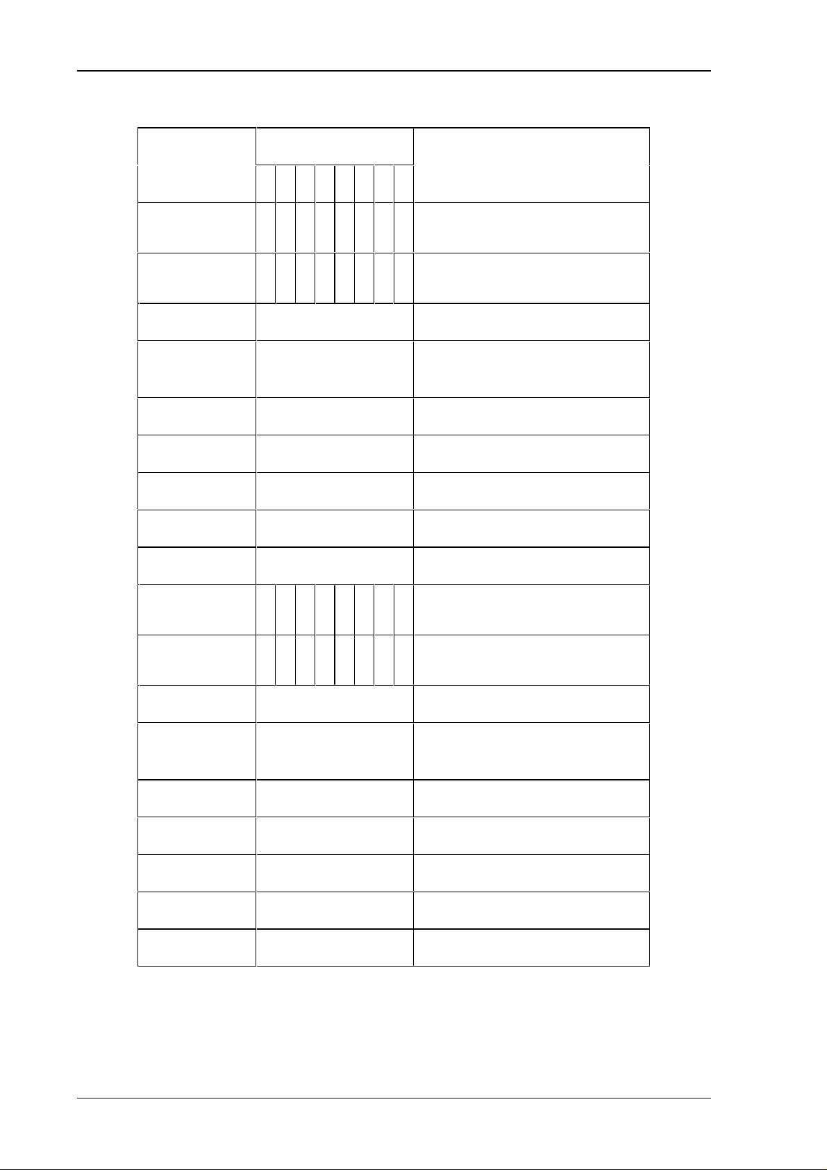
Address Address Bits Contents
(hex)
76543210
C00 1 x 0 0 0 0 0 0 ’Data Valid’ of channel 0
( for Data transfer VME -> C1300)
C00 x1000000’Quit’ of channel 1
( for Data transfer C1300 -> VME)
C01 Length ( from 2 to FEh)
C02 Function number
( 1 bis FEh )
C03 Argument 0
.. ..
Cnn Argument n
.. ..
CFF ..
D00 1x000000’Data Valid’ of channel 1
( for Data transfer C1300 -> VME)
D00 x1000000’Quit’ of channel 0
( for Data transfer VME -> C1300)
D01 Length (from 2 to FEh)
D02 Function number
( 1 to FFh )
D03 Argument 0
.. ..
Dnn Argument n
.. ..
DFF ..
Addresses of Handshake Channels
Page 14 of 44 Version : 2.01 Date : 18.12.95
Page 15

C1300 VME to II/O Interface Unit Beckhoff II/O-System
Handshake sequence :
:0C00 80h Data Valid VME-Master = 1
:0D00 40h Data ACK C1300 = 1
:0C00 00h Data Valid VME-Master = 0
:0D00 00h Data ACK C1300 = 0
. . . function process
:0D00 80h Data Valid C1300 = 1
:0C00 40h Data ACK VME-Master = 1
:0D00 00h Data Valid C1300 = 0
:0C00 00h Data ACK VME-Master = 0
Date : 18.12.95 Version : 2.01 Page 15 of 44
Page 16

C1300 VME to II/O Interface Unit Beckhoff II/O-System
Functions provided are :
No.
(hex)
01 LWL-RESET
02 codewort request
03 softwareversion request
04 reserved
05 absorbtion test
06 count modules
07 address test
08 continuous transmission
09 software-RESET
0a fraction test
0b transmission of free programmable
Function
communications
0c reinitializiation of CDL management
0d reserved
0e reserved
0f transmission of interrupt mask
10 transmission of CDL configuration
ff reserved
A function call consists of a length, a function number and the arguments of the function. The
length is calculated by number of the following bytes.
:
Byte ’Length’ + Byte ’function number’ + Number of Bytes ’Argument 0’ up to ’Argument n’
In case a reserved function or a function that is not available is called, the response to this call
is the error function ffh.
Page 16 of 44 Version : 2.01 Date : 18.12.95
Page 17

C1300 VME to II/O Interface Unit Beckhoff II/O-System
3.3. Test and Analysis Functions
Function 01h : FO-RESET
This function initialzes the fo-ring.In the course of the initialization the number of
modules in the ring is detected, the module addresses are distributed and tested.
Finally the ring is tested for its (Dämpfungsreserve). A fraction that could occur in
the cable is detected and localized.
channel length function argument 0 argument 1 argument 2 comment
call
response
02 01
05 01 00 00 nn
05 01 01 01 00
05 01 01 02 00
05 01 0a 01 nn
05 01 0a 01 ff
05 01 07 01 nn
05 01 05 02 00
05 01 05 03 nn
Function worked properly
(nn modules in the fo-ring)
Maximum of transm ission
repetitions exceeded
No addressing possible
Fraction before module nn,
before receiver line in of
module C1300
Fraction cannot be localized
( fraction before
line in of receiver )
Test addresses :
Address error ( modul nn)
Absorbtion test :
error at High-Intensity
Absorbtion test :
Error switching low intensity
( modul nn)
05 01 05 04 nn
05 01 05 05 nn
05 01 05 06 nn
05 01 05 07 nn
Absorbtion test :
Error at data pattern 1
( pattern 00) (module nn)
Absorbtion test :
Error data pattern 2
( pattern FF) (module nn)
Absorbtion test :
Error data pattern 3
( pattern AA)(module nn)
Absorbtion test :
Error switching high-intensity
(module nn)
If the ring initialization is completed and no errors occured, the present number of
modules in the ring is transmitted. If an error was detected, the error type (see
table) and the modul addresses of the error detecting module are returned.
Date : 18.12.95 Version : 2.01 Page 17 of 44
Page 18

C1300 VME to II/O Interface Unit Beckhoff II/O-System
Funktion 02h : Code word request
After each reset the code word is transmitted through the handshake channels by
the C1300 module. This is done without setting the data valid bit. The code word
is used to report that the C1300 module is initialized and ready to work to the
VME system. At any time the code word can be requested by function 02h.
channel length function argument0argument1 argument
2
call
response
02 02
04 02 af fe
comment
codeword correct
Page 18 of 44 Version : 2.01 Date : 18.12.95
Page 19

C1300 VME to II/O Interface Unit Beckhoff II/O-System
Function 03h : Softwareversion request
Function 03h is used to request the the version of the EPROM firmware.
channel length function argument0argument1argument
2
call
response
02 03
04 03 xx xx
comment
version xxxx
Date : 18.12.95 Version : 2.01 Page 19 of 44
Page 20

C1300 VME to II/O Interface Unit Beckhoff II/O-System
Function 05h : Absorbtion test
The light absorbtion of the fo-ring can be tested by means of this function. In this
test all connection cables of the fo-ring are partially run at about 80 % of the
normal transmission intensity using specified test telegrams. This test can be run
on all modules or on a single one selected before ( shown in the figure below ).
The C1300 interface can be tested seperately or through module address 0.
" Error at high intensity " means: The ring has even in a normal run an absorbtion
that is too high or a fraction of cables or connection occured.
" Error switching Low intensity " means, that the transmission intensity of the
module concerned cannot be reduced.
"Error at data pattern xx " shows up that in the fo-ring absorbtion is too high, after
the signal passed the last module .
" Error switching high intensity " means the module concerned cannot be reset
to full transmission intensity.
This figure shows an overview of the function call and responses possible.
channel length function argument0argument1argument
2
call
response
04 05 00 00
04 05 01 nn
04 05 00 00
04 05 02 00
04 05 03 nn
04 05 04 nn
04 05 05 nn
comment
test all modules
test module nn
there is sufficient absorbtion
(*)
error at High-Intensity
error switching Low-Intensity
( module nn)
error at Data patt ern 1
( pattern 00) (module nn)
error at Data patt ern 2
( pattern FF) (modul nn)
04 05 06 nn
04 05 07 nn
error at Data patt ern 3
( pattern AA)(module nn)
error switching High-Intensity
(Modul nn)
Page 20 of 44 Version : 2.01 Date : 18.12.95
Page 21

C1300 VME to II/O Interface Unit Beckhoff II/O-System
Funktion 06h :Count Modules
By means of this function the number of modules in the ring can be detected.
channel length function argument 0 argument 1 argument 2 comment
call
response
02 06
04 06 00 nn
04 06 01 00
count modules :
nn modules in the ring
count modules :
ring interrupted
Date : 18.12.95 Version : 2.01 Page 21 of 44
Page 22

C1300 VME to II/O Interface Unit Beckhoff II/O-System
Funktion 07h : Address test
This function is used to prove if the modules still hold the address, they received
when they were initialized.
channel length function argument0argument1argument
2
call
response
02 07
04 07 00 00
04 07 01 nn
In order to keep a maximum of safety for the system, this function is even run
resident when the system is working normally. In case an error is detected a
message is transmitted through the GCB to the VME system.
comment
addresses correct
error at address nn
Page 22 of 44 Version : 2.01 Date : 18.12.95
Page 23
C1300 VME to II/O Interface Unit Beckhoff II/O-System
Funktion 08h : continuous transmission
This function only controls the "cycle"-LED on the modules.This way it is
possible to find out how many modules are still connected to the transmission
output of the C1300. This function is only supposed to be activated, if there is no
satisfying result from the function 0ah ( fraction test ).The only way for the
software to stop continuous transmission is a reset .
channel length function argument0argument1argument
2
call
response
02 08
03 08 01
While continuous transmission is working the functions 05h to 07h and 0ah are
inhibited.
comment
constant transmission can be
stopped by reset
Date : 18.12.95 Version : 2.01 Page 23 of 44
Page 24

C1300 VME to II/O Interface Unit Beckhoff II/O-System
Funktion 09h : Software-RESET
This Function is used to to reset the C1300. Apart from reinitializing fo-ring the
controller and the dual port RAM are reinitilized too.The finished reset is quitted,
transmitting the codeword without a data valid.
The software reset is only executed, after the data quit bits in handshake channel 1
and the data valid in handshake 2 were removed.
channel length function argument0argument1argument
2
call
response
02 09
04 02 fe af
comment
Page 24 of 44 Version : 2.01 Date : 18.12.95
Page 25

C1300 VME to II/O Interface Unit Beckhoff II/O-System
Funktion 0ah : Fraction Test
This function can be used to localize fractions in the fo-ring.The function
evaluates the result and then returns the number of Boxes in the ring or the place
of the fraction.
channel length function argument 0 argument 1 argument 2 comment
call
response
02 0a
04 0a 00 nn
04 0a 01 nn
04 0a 01 ff
no fractions,
nn modules in the ring
fraction before modul nn and
before the line in of the receiver
of
module C1300
fraction cannot be localized
(fraction before receiver line
in)
in case the fraction cannot be localized, the probable location is between the last
module and the receiver line in of the C1300.
Date : 18.12.95 Version : 2.01 Page 25 of 44
Page 26

C1300 VME to II/O Interface Unit Beckhoff II/O-System
Funktion 0ffh: Wrong Function
in case there is a function call through handshake channel 0 and the function is
reserved or not available,it is returned with function 0ffh, which has as argument 0
the wrong function number.
Example:
channel length function argument0argument1argument
2
call
response
03 04 01
03 0ff 04
comment
call of function 4
( reserved )
Page 26 of 44 Version : 2.01 Date : 18.12.95
Page 27

C1300 VME to II/O Interface Unit Beckhoff II/O-System
3.4. Configuration
There are four functions to describe the configuration, assignments of the input and output
lines of the II/O System for the addresses in the DPRAM, and assignment of modules to the
process groups.For the transmission of configurations handshake channels are used as well. At
the beginning of every new configuration the managing part of communications is to be
reinitialized.
Communications can either be configured as CDL communications or as free programmable
communications.
Date : 18.12.95 Version : 2.01 Page 27 of 44
Page 28

C1300 VME to II/O Interface Unit Beckhoff II/O-System
Funktion 0ch : reinitialize communication management
The CDLs as well as the free programmable communication consist of two parts a
data and a managing part. Before a new communication is transmitted the
managing part must be reset.This is done by activating the function 0ch.
channel length function argument0argument1argument
2
call
response
02 0c
02 0c
comment
Page 28 of 44 Version : 2.01 Date : 18.12.95
Page 29

C1300 VME to II/O Interface Unit Beckhoff II/O-System
Example:
3.4.1. CDL-Communication
A CDL is created for each group of modules, whose signal states are to be activated
together.This CDL consists of so-called descriptors. A descriptor describes a telegram for a
module (message) and is built up as follows:
Bytes Inhalt
0,1 II/O-module addresse (1 - FE)
2,3 Control word :
Bit 4 : 0 = READ; 1 = WRITE
Bit 5 : 1 = address initialization
Bit 6 : 1 = address count command
Bit 7 : 1 = switch to low intensity
4,5 Pointer to byte for output in D0 of a message
6,7 Pointer to byte for output in D1of a message
8,9 Pointer to byte for output in D2 of a message
10,11 Pointer to byte for output in D3 of a message
12,13 Pointer to byte for input in D0 of a message
14,15 Pointer to byte for input in D1 of a message
16,17 Pointer to byte for input in D2 of a message
18,19 Pointer to byte for input in D3 of a message
Date : 18.12.95 Version : 2.01 Page 29 of 44
Page 30

C1300 VME to II/O Interface Unit Beckhoff II/O-System
Example of a descriptor:
Telegram to II/O-module 1 : D0 - D2 output line
D3 input line
The data for output in D0 - D2 is loaded from the addresses 400h, 302h and 210h of the
DPRAM.
The Date for the input in D3 is stored at address 30h of the DPRAM.
Bytes Inhalt
0,1 01h,00
2,3 10h,00
4,5 00h,04
6,7 02h,03
8,9 10h,02
10,11 ffh,ff
12,13 ffh,ff
14,15 ffh,ff
16,17 ffh,ff
18,19 30h,00
h
h
h
h
h
h
h
h
h
h
Page 30 of 44 Version : 2.01 Date : 18.12.95
Page 31

C1300 VME to II/O Interface Unit Beckhoff II/O-System
Funktion 10h: Transmit CDL-Configuration
The CDLs described above are split into parts, so that they can be transmitted
through the handshake channel 0. The information for a message should not be
split in this process. Transmission can be activated by function 10h
channel length function
(hex)
call
channel length function argument0argument1argument
response
nn 10 00 aa bb db1,0 dbn,19
04 10 aa 00 o.k.
04 10 aa 01 CDL data error
04 10 aa 02 CDL overflow
aa
empty argument0argument1argument2... argument
2
00 = start of CDL transfers
01 = further Descriptors of the same CDL
02 = last transmission of the same CDL
n
comment
(
e.g.: Pointer outside Data area
of DPRAM
)
bb
db1,0
...
dbn,19
signal state No. bb ( 0 - 7)
desciptor 1, byte 0 of a CDL
...
desciptor n, byte 19 of a CDL
Transmissions of module addresses, control byte and pointer to data bytes are
established in Intel Notation ( lower Byte to lower address ).
Date : 18.12.95 Version : 2.01 Page 31 of 44
Page 32

C1300 VME to II/O Interface Unit Beckhoff II/O-System
3.4.2. Free programmable Communication
This way of communication is done by storing telegrams at a predefined address of the
DPRAM, and combining them together to create a process image. The input data is
transmitted to the VME interface to a predefined address.
Page 32 of 44 Version : 2.01 Date : 18.12.95
Page 33

C1300 VME to II/O Interface Unit Beckhoff II/O-System
Funktion 0bh: Initialization of free programmable communication
This function is used to transmit the parameters, needed for initialization, to the
C1300.
channel length function empty argument0argument1argument2argument
3
call
09 0b 00 ssn nt oa 0,1 ia 0,1
channel length function argument
0
response
03 0b 00 ok
03 0b 01 error
comment
ssn signal state number
nt number of telegrams
oa 0,1 base address output area
ia 0,1 base address input area
The base address output area defines the area in the DPRAM, where the self
defined telegrams are stored. Only address byte, control byte and four data bytes
are stored. There is no check byte stored. This is done internally by the controller.
Beginning at the base address input area address byte, control byte and entry data
are stored.
Date : 18.12.95 Version : 2.01 Page 33 of 44
Page 34

C1300 VME to II/O Interface Unit Beckhoff II/O-System
Example:
Initialization of communication 3 as a free communication with 2 telegrams. Base addres for
the output area is 400h base address for the input area is 210h
channel length function empty argument0argument1argument2argument
3
call
09 0b 00 03 02 00,04 10,02
channel length function argument
0
response
03 0b 00 ok
comment
using this structure there is the possibility of a run-time change of module address and control byte. But this is restricted to phases when there are no active communications.
Page 34 of 44 Version : 2.01 Date : 18.12.95
Page 35

C1300 VME to II/O Interface Unit Beckhoff II/O-System
Function 12h: Free running communication
Function 12h enables a free running communication, which is executed by the
interface without a trigger of the VME system. The usual handshake to
synchronize communication and process image control via the GCB is not
necessary.
Channel Length Function Argument 0 Argument 1
Request
Channel Length Function Argument 0
Reply
04 12 k pan
Comment
03 12 00 00 says: ok
03 12 01 01 says: erroneous data
with:
pan process image number
k Command code
0 = disable free running
communication
1 = enable free running
communication
It is highly recommended to use this mode only with byte - oriented I/O functions,
due to the fact that no deterministic behaviour exists between request and response
data and between two adajcent read or write access events of the VME Master:
The process image data might result from different communication cycles.
Date : 18.12.95 Version : 2.01 Page 35 of 44
Page 36

C1300 VME to II/O Interface Unit Beckhoff II/O-System
3.4.3. Initialisation of "Fast Fiber Optic - Interrupts"
Function 0fh : Transmit interrupt request mask
The interface C1300 has 4 interrupt channels to transmit the 4 interrupt channels
of the II/O-Lightbus to the VME master via the GCB block.
The interrupt bits are generated by any module of the II/O Lightbus in any
occuring telegram frame. The IR- bit field of the control byte transports the
interrupt requests to the interface.
With the help of function 0fh, the interface C1300 is configured. It is possible to
enable a number of interupts from the four channels and to specify the signal type
to generate an interrupt request transmission from the C1300 interface to the VME
system.
Channel Length Function Argument0Argument1Argument2Argument3Argument
4
Request
Response
07 0f 0m
03 0f 0m
Criterium
Interrupt-
Channel 0
Criterium
Interrupt-
Channel 1
Criterium
Interrupt-
Channel 2
Criterium
Interrupt-
Channel 3
The LOW - nibble in argument 0 specifies, which of the 4 possible Interrupt
channels are enabled.
Example:
m = 00
m = 01
m = 06
m = 0f
h
all interrupt channels disabled ( default )
h
interrupt channel 0 enabled
h
interrupt channels 1 and 2 enabled
h
interrupt channels 0, 1, 2 and 3 enabled
Every single interrupt channel can be characterized with signal criteria.
Following criterias can be definded:
Criterium Argument code
no interrupt 0
interrupt at signal rise 1
interrupt at signal fall 2
interrupt at signal toggle 3
The argument codes 0 to 3 are defined in the function parameters Argument 1 to 4
for the equivalent interrupt channels.
Page 36 of 44 Version : 2.01 Date : 18.12.95
Page 37

C1300 VME to II/O Interface Unit Beckhoff II/O-System
Example:
Channel Length Function Argument0Argument1Argument2Argument3Argument
4
Request
Enable interrupts for channels 2
and 3
Interrupt criterium for interrupt
channel 0
no interrupt transmission
Interrupt criterium for interrupt
channel 1
no interrupt transmission
Interrupt criterium for interrupt
channel 2
Interrupt transmission at signal rise
Interrupt criterium for interrupt
channel 3
Interrupt transmission at signal
toggle
07
h
0f
h
0c
h
00
h
00
h
01
h
03
h
Important remark:
To enable interrupt transmisson from the C1300 interface to the VME system, the
interrupt level mask and the interrupt vector register of the GCB have to be
defined.
Date : 18.12.95 Version : 2.01 Page 37 of 44
Page 38

C1300 VME to II/O Interface Unit Beckhoff II/O-System
3.5. Signal state control functions
The General Control Block is used for controlling the refresh of a single signal state. It will be
refreshed and, through the ready mask, reported ready by setting the corresponding bit in the
call mask. After it was reported ready the bit must be cleared from the call mask, only then
communications can be started again. The refresh of signal states can be interrupted. When
there is a refresh in process and if there is a refresh of a higher priority called in the call mask,
the process is interrupted.
In case errors are detected in the fo-ring in a normal system run, the corresponding bits in the
error mask are set.
Address
Contents Comment
(hex)
0FFF call mask
0FFE IRQ-output
0FFD ready mask
0FFC IRQ-input
0FFB write protection
0FFA error mask
0FF9 -
... -
0FF1 VMEbus Interrupt
Vector
The value 02h removes the write
protection
reserved for later use
- " -
Vector numbers 0h-FFh for D08
interrupter
0FF0 VMEbus Interrupt
Level
2h = IRQ1,4=IRQ2 80h=IRQ7
mask register
General Control Block
Page 38 of 44 Version : 2.01 Date : 18.12.95
Page 39

C1300 VME to II/O Interface Unit Beckhoff II/O-System
call mask:
P8 P1
<- - priority
ready mask:
P8 P1
with : P8 => process 08,
.......,
P1 => process 01
Error mask:
Error mask. Bit 0 set = normal error
Error mask. Bit 1 set = address error with addresscheck
Write protection:
DPRAM operations of the VME system must be enabled by deactivating the write
protection. By writing a 02h the write protection remains removed, until a
different date is written.
E8 E1
Date : 18.12.95 Version : 2.01 Page 39 of 44
Page 40

C1300 VME to II/O Interface Unit Beckhoff II/O-System
IRQ Data out:
----IO3IO2IO1IO0
If the VME system modifies this mask it will be transmitted into the interrupt field. The nibble
will be transmitted into the interrupt field, untill it is removed by the VME system.
IRQ Data in:
- - - - II3 II2 II1 II0
If a peripheral module generates an address-independent interrupt and if this interrupt is
released by the interrupt mask, it is transmitted through this mask to to the VME system.
Queueing interrupts are buffered by the C1300, i.e. there is only one interrupt at a time
transmitted through the GCB to the VME system. Only after this one was recognized by the
VME system ,the next interrupt can be transmitted
VMEbus interrupt vector and interrupt level register:
The C1300 includes a D08-VMEbus Interrupter. The interrupt vector may be dynamically
loaded at address 0FF1h and transfered to the VMEbus at the next valid IACK-cycle.The
interrupt level can be programmed at address 0FF0h. Only one interrupt level should be
activated at one time. Bit 0 of the interrupt level register has no meaning.
Page 40 of 44 Version : 2.01 Date : 18.12.95
Page 41

C1300 VME to II/O Interface Unit Beckhoff II/O-System
4. Technical Data
Port prozessor
Data connections
Transmission rate
Power supply
Size
Siemens SAB 80C166-S
Beckhoff II/O Lightbus system
2,5 MBaud, 32 Bit of informations in 25 µsec
from the VME Bus
PCB dimensions 100 mm x 160 mm
Front panel width about 20 mm
Date : 18.12.95 Version : 2.01 Page 41 of 44
Page 42

C1300 VME to II/O Interface Unit Beckhoff II/O-System
5. Installation
5.1. Configuration
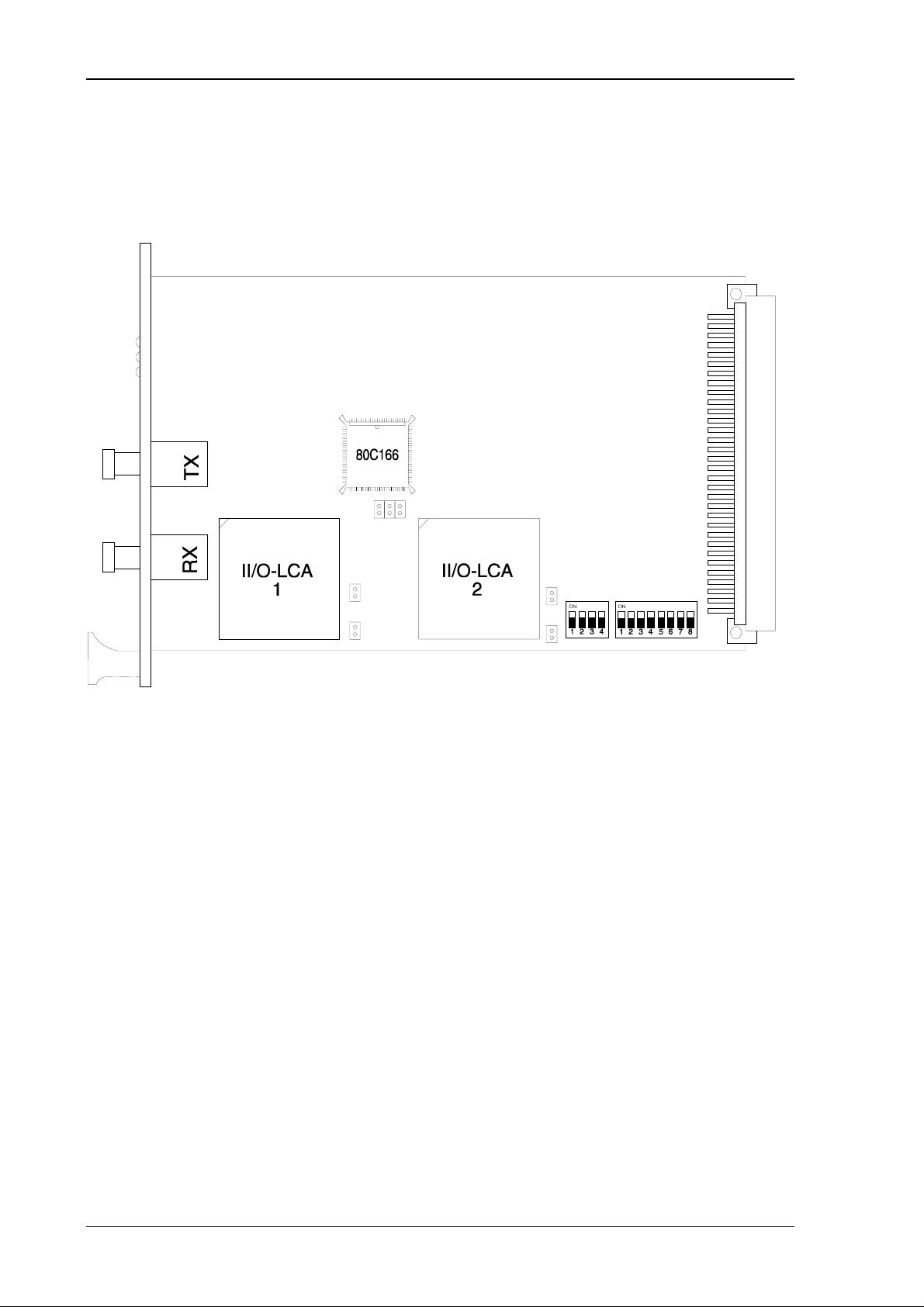
The central module C1300 needs only a single slot and can be installed in 3-HE and 6-HE
VMEbus crates. The connection to the II/O-system is established by two FO-plugs through the
front. The adjustment of the base address for the 4 kByte workspace occupied in the VME
address space is to be done by two DIP switches. The whole 16 MByte address space of the
VME system can be selected in the A24 mode as mapping area.
The switch positions represent the address lines A12-A23:
Switch: SW100 SW101
1234 12345678
Address Bit: 12 13 14 15 16 17 18 19 20 21 22 23
The switch position ”on” represents a logic 0, ”off” represents a logic 1.
Switch :
Position on * * * * * * * * 00 0000h - 00 0fffh
off
on * * * * * * * 10 0000h - 10 0fffh
off *
on * * * * * * * 20 0000h - 20 0fffh
off *
on * * * * * * 30 0000h - 30 0fffh
off **
on * * * * * * * * * * 80 8000h - 80 8fffh
off **
on ff f000h - ff ffffh
off ************
SW 100 SW 101
123412345678
Address
Page 42 of 44 Version : 2.01 Date : 18.12.95
Page 43

C1300 VME to II/O Interface Unit Beckhoff II/O-System
Date : 18.12.95 Version : 2.01 Page 43 of 44
Page 44

C1300 VME to II/O Interface Unit Beckhoff II/O-System
5.3. Installation on the VME Card Cage
1. Switch off the VME system and external power supply.
2. The module is installed in a slot of the VME Card Cage
A VME system run will also start the C1300. But before running the C1300, all fiber optic
connections have to be established and the C1300 must be configurated correctly.
Page 44 of 44 Version : 2.01 Date : 18.12.95
 Loading...