

Page 1
ISA-Bus interface card
C1230S
Supplement for Industrial PCs with
standard motherboard
Technical hardware description
Version 1.0
Version 1.0
Page 2

Page 3

Table of Contents
1.
Overview 4
2. Pin Assignment for the Connections 5
AT bus 5
System bus; front panel; UPS 6
3. The C2000BAT UPS Control Board 7
4. Programming 8
The 8255 Parallel Input/Output Chip 8
The Special Keys 8
The LEDs 9
The C2000BAT UPS Control Board 10
Controlling the LCD Background Illumination 10
Uninterruptible Power Supply 11
The Charging System 11
Eiserstraße 5 / D-33415 Verl / Phone 05246/963-0 / Fax 05246/963-149
Table of Contents 3
5. Operating Conditions 13
C1230S
Page 4

Eiserstraße 5 / D-33415 Verl / Phone 05246/963-0 / Fax 05246/963-149
4 ISA Bus interface card C1230S
Overview
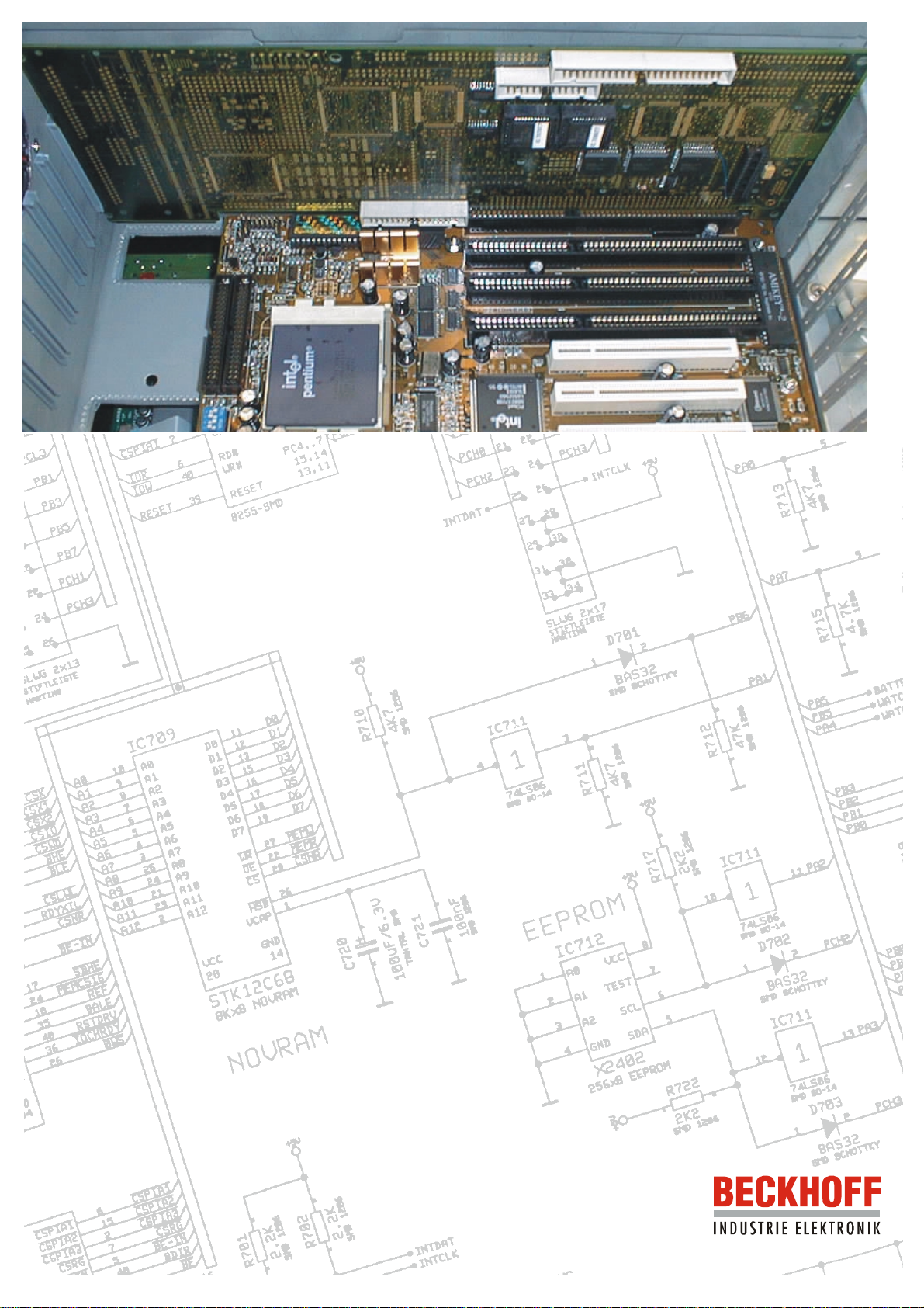
The ISA bus C1230S PC interface card provides an extension to industr y
PCs with standard motherboar ds for the drive of vario us IPC components
that are not present in standard PCs.
The C1230S allows up to 10 special k eys to be interrogate d, and up to 10
LEDs to be driven. T he card, in combination with the C2000 BAT control
board, allows a 24V UPS (uninterru ptible power supply) to be driven. The
industry PC can also be given an NC bac kplane, driven by means of the
C1230S interface card. The NC backplane makes 32 digital inputs, 32
digital outputs, 4 analogue inputs, 4 analogue outputs and 4 incremental
encoder inputs available centrally at the PC. The function and
programming of the NC backplane are described in a separate NC
backplane documentation.
The C1230S interfac e c ard is a partially pop ulated v ar ia nt of the C12 30 Al lin-One motherboard.
6\VWHP%XV
67
)URQWWDEOHDX
67
67
869
67
Connections for:
• C2000BAT control board for uninterruptible power supply
• NC backplane
• Front panel
C1230S
Page 5
Eiserstraße 5 / D-33415 Verl / Phone05246/963-0 / Fax 05246/963-149
ISA Bus interface card C1230S 5
Pin Assignment for the Connections
AT bus
Pin assignment
ST 1000 AT
bus
A1
A2
A3
A4
A5
A6
A7
A8
A9
A10
A11
A12
A13
A14
A15
A16
A17
A18
A19
A20
A21
A22
A23
A24
A25
A26
A27
A28
A29
A30
A31
Function Pin assignment
ST 1000 AT
bus
IOCHK#
SD7
SD6
SD5
SD4
SD3
SD2
SD1
SD0
IOCHRDY#
AEN
SA19
SA18
SA17
SA16
SA15
SA14
SA13
SA12
SA11
SA10
SA9
SA8
SA7
SA6
SA5
SA4
SA3
SA2
SA1
SA0
B1
B2
B3
B4
B5
B6
B7
B8
B9
B10
B11
B12
B13
B14
B15
B16
B17
B18
B19
B20
B21
B22
B23
B24
B25
B26
B27
B28
B29
B30
B31
Function Pin assignment
ST 1000 AT
bus
GND
RESETDRV
VCC
IRQ9
-5V
DRQ2
-12V
CARDSLCT#
+12V
GND
SMEMW#
SMEMR#
IOW#
IOR#
DACK3#
DRQ3
DACK1#
DRQ1
REF#
SYSCLK
IRQ7
IRQ6
IRQ5
IRQ4
IRQ3
DACK2#
T/C
BALE
VCC
OSC
GND
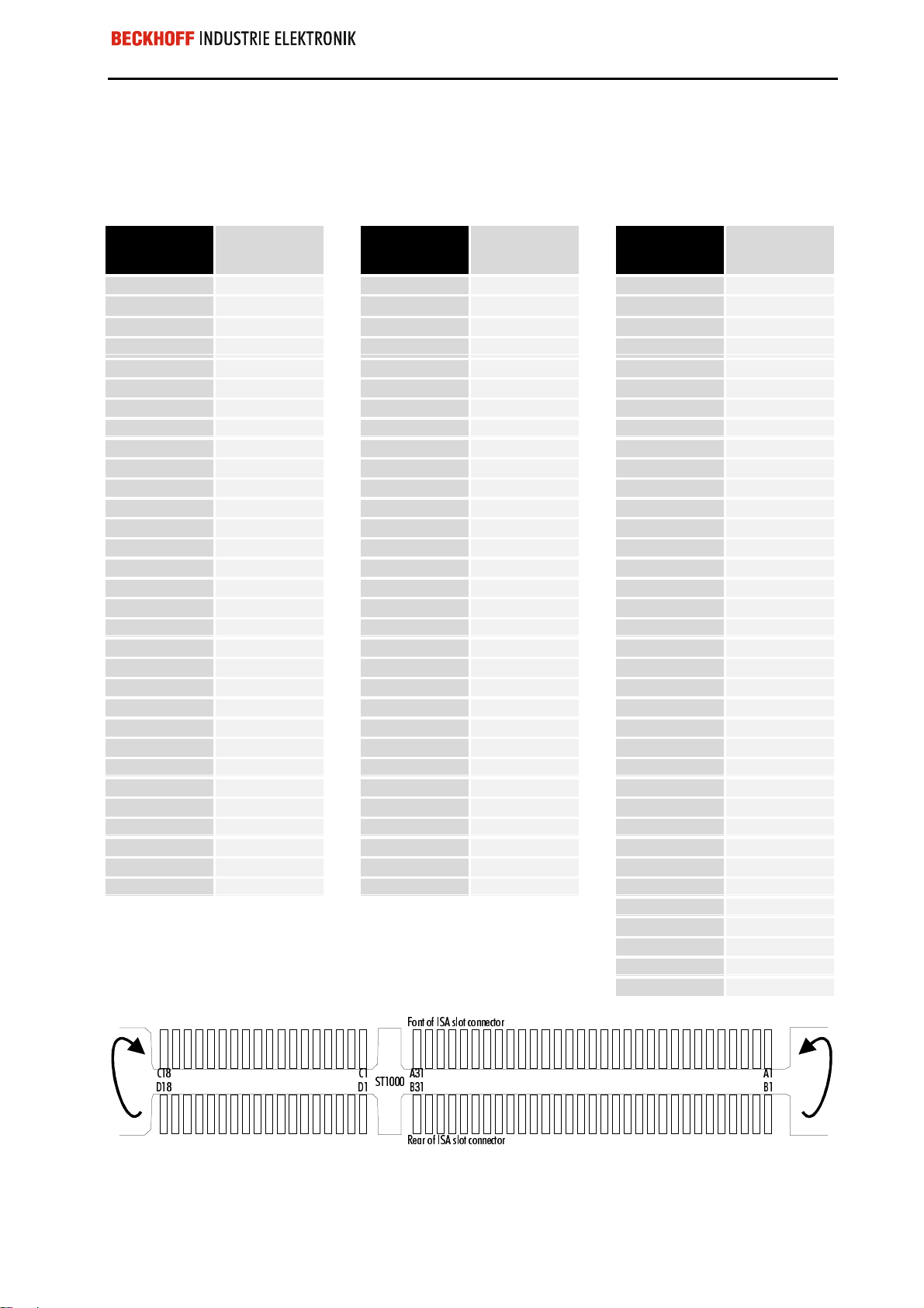
C1
C2
C3
C4
C5
C6
C7
C8
C9
C10
C11
C12
C13
C14
C15
C16
C17
C18
D1
D2
D3
D4
D5
D6
D7
D8
D9
D10
D11
D12
D13
D14
D15
D16
D17
D18
Function
SBHE#
LA23
LA22
LA21
LA20
LA19
LA18
LA17
MEMR#
MEMW#
SD8
SD9
SD10
SD11
SD12
SD13
SD14
SD15
MEMCS16
IOCS16
IRQ10
IRQ11
IRQ12
IRQ15
IRQ14
DACK0#
DRQ0
DACK5#
DRQ5
DACK6#
DRQ6
DACK7#
DRQ7
VCC
MASTER#
GND
)RQWRI,6$VORWFRQQHFWRU
67
5HDURI,6$VORWFRQQHFWRU
$$&&
%%''
C1230S
Page 6

Eiserstraße 5 / D-33415 Verl / Phone 05246/963-0 / Fax 05246/963-149
6 ISA Bus interface card C1230S
System bus; front panel; UPS
Pin assignment
ST 701
system bus
1
2
3
4
5
6
7
8
9
10
11
12
13
14
15
16
17
18
19
20
21
22
23
24
25
26
27
28
29
30
31
32
33
34
35
36
37
38
39
40
41
42
43
44
45
46
47
48
49
50
Function Pin assignment
ST 702
front panel
GND
GND
D0
D8
D1
D9
D2
D10
D3
D11
D4
D12
D5
D13
D6
D14
D7
D15
GND
GND
A0
A1
A2
A3
A4
A5
A6
A7
BLE#
BHE#
MEMR#
MEMW#
GND
GND
CSK#
CSX1#
CSX2#
CSWD#
CSIO#
GND
PWRGOOD
KBCLK-EXT
+5v
+5v
+5v
+5v
+5v
GND
KBDATA-EXT
GND
1
2
3
4
5
6
7
8
9
10
11
12
13
14
15
16
17
18
19
20
21
22
23
24
25
26
27
28
29
30
31
32
33
34
Function Pin assignment
ST 703 UPS
PA0
PA1
PA2
PA3
PA4
PA5
PA6
PA7
PCL0
PCL1
PCL2
PCL3
PB0
PB1
PB2
PB3
PB4
PB5
PB6
PB7
PCH0
PCH1
PCH2
PCH3
INTDAT
INTCLK
+5V
+5V
+5V
+5V
GND
GND
GND
GND
1
2
3
4
5
6
7
8
9
10
11
12
13
14
15
16
17
18
19
20
21
22
23
24
25
26
Function
PA0
PA1
PA2
PA3
PA4
PA5
PA6
JUMP
PCL0
PCL1
PCL2
PCL3
PB0
PB1
PB2
PB3
PB4
PB5
PB6
PB7
PCH0
PCH1
PCH2
PCH3
+5V
GND
C1230S
Page 7

Eiserstraße 5 / D-33415 Verl / Phone05246/963-0 / Fax 05246/963-149
ISA Bus interface card C1230S 7
The C2000BAT UPS Control Board
Uninterruptible power
supply
Not all connections are
used in the applicat ion with
the C1230S.
An industry PC with a 24 V power supply can optionally be f itted with an
uninterruptible power supply, which maintains correct operation of the
device for about 15 minutes by means of a NiCad battery after failure of the
main power supply. The control is performed by the C2000BAT UPS
control board.
Battery/Pwr. sup.
Fuse
Mains power
supply board
1A
LCdisplay
C1230S
1
not
not
used
11
used
Battery reverse connection
protection
Switch for the LCD
background illumination
Switch for
LCD illumination
The UPS control board is fitted with a simple form of protection against
reverse battery connection. If the batter y is acciden tally conn ected with th e
wrong polarity, high c urr ent f lo ws f or a sh or t period, and this blo ws th e f use
(1A) on the C2000BAT board. The locatio n of the f use on t he board c an b e
seen in the figure.
The UPS control board allows the LCD background illumination to be
switched on and off by means of a switch on the side of the hous ing, or b y
software through the PIO chips on the C1230S. Switching the LCD
background illum ination off can save cur rent u nder batter y operatio n. If the
software has switched the bac kground illumination off when under battery
power, it can be switched on again for operation using the switch.
BECKHOFF C2000BAT
C1230S
Page 8

Eiserstraße 5 / D-33415 Verl / Phone 05246/963-0 / Fax 05246/963-149
8 ISA Bus interface card C1230S
Programming
The 8255 Parallel Input/Output Chip
There are three 8255 parallel input/output chips, PIOs for short, on the
C1230S ISA bus car d. One of these components int errogates the special
keys on the front pan el and controls the LEDs. If your PC does not have
special keys, the chip ca n be used for other purposes. T he connections to
the chip are brought to the C1230S card’s front panel interface in TTL
compatible form . The s econd PIO contro ls an uninter rupt ible po wer s uppl y.
You need the C2000B AT UPS control boar d in order to connect the UPS.
The third chip is not used on the C1230S card.
Each component has t hree 8-bit ports that can be configured as inputs or
outputs. The configuratio n is made through the contro l register. Each port
and each control register is located at a memory address.
The addresses of the three
PIO chips on the C1230S
Configuration:
After power-up, write 91H
into address 223H and 93 H
into address 233H.
Each of the 10 special k eys
contains an LED
Front panel Address UPS
control
Port A
Port B
Port C
Control
register
220H
221H
222H
223H
Port A
Port B
Port C
Control
register
Address not used Address
230H
231H
232H
233H
Port A
Port B
Port C
Control
register
240H
241H
242H
243H
In the control register of an 8255 parallel input/output component you
specify which port will function as input or output.
After a reset, or after the com puter has been switched o n, all the p orts are
configured as inputs. In order to configure the chip appropriately for its
tasks in the industry PC, write the value 91H into the control register at
address 223H, and 93H into address 233H. The configurati on is retained
until these addresses are over-written, or until the computer is re-booted.
The Special Keys
The industry PC has up to 10 special keys on the front panel, each of
which contains an LED.
C1230S
The special keys on the front panel are not connected via the keyboard
interface, but are interr oga ted by means of port A and th e lo wer par t of por t
C of the parallel input/output c hip , wh ose a ddr es s r ange l ies b et ween 220H
and 223H.
Page 9

Eiserstraße 5 / D-33415 Verl / Phone05246/963-0 / Fax 05246/963-149
ISA Bus interface card C1230S 9
Special
keys
Port
Address
Bit
Pressed=
Cleared=
S10 S9 S8 S7 S6 S5 S4 S3 S2 S1
Port C Port A
222H 220H
1 0 7 6 5 4 3 2 1 0
0 0 0 0 0 0 0 0 0 0
1 1 1 1 1 1 1 1 1 1
Since, after a reset , all the com ponent’s ports are config ured for input, the
keys can be interrogated without altering the control register.
Example:
- Press keys S5 and S9, and interrogate addr esses 220H and 222H at the
same time.
- From address 220H you obtain 11101111B, while 222H returns
XXXXXX10B. The X stands here for an undefine d value that need not be
considered.
The LEDs
The 10 special keys each contain a lig ht emitting diode t hat can be driven
through the software. They are addressed through port B and the upper
half of port C of the same input/output component as the sp ec ia l keys. This
is located in the address range from 220H to 223H.
Inverted drive
The component must b e reconfigured for output in the
control register.
Note that drive of the LEDs is inver ted, so that if the bit is set, the LED is
out.
Since after a reset all the component’s ports are configured as inputs, the
value 10010001B (= 91H) must be written into the control register at
address 223H before the LEDs are first used, s o that port B and the upper
half of port C function as outputs. The configur ation is retained unti l this is
over-written.
Example:
- Write 10010001B (91H) into address 223H.
- In order to switch on LED 6 and to s witch all the others off, write DFH to
address 221H and set bits 4 and 5 of address 222H, by writing a va lue in
which bits 4 and 5 are 1, for instance 30H or FFH.
LEDs 10 9 8 7 6 5 4 3 2 1
Port
Address
Bit
LED on=
LED off=
Port C Port B
222H 221H
5 4 7 6 5 4 3 2 1 0
0 0 0 0 0 0 0 0 0 0
1 1 1 1 1 1 1 1 1 1
C1230S
Page 10

Eiserstraße 5 / D-33415 Verl / Phone 05246/963-0 / Fax 05246/963-149
10 ISA Bus interface card C1230S
The C2000BAT UPS Control Board
Uninterruptible power
supply
Configure the component
An industry PC with a 24 V power supply can optionally be f itted with an
uninterruptible power supply, which maintains correct operation of the
device for about 15 minutes by means of a NiCad battery after failure of the
main power supply.
Control is exercis ed by the C2000BAT UPS contro l board. It is accessed
through the parallel input/output chip located in the address range from
230H to 233H. The value 93H must be writte n into the control register at
address 233H in order to configure the component.
Register Address Function
Port A
Port B
Port C
lower half
Port C
upper half
Control
register
Port C
Address 232H
Bit 7 Bit 6 Bit 5 Bit 4 Bit 3 Bit 2 Bit 1 Bit 0
Output Input
UPS
active/
passive
0=passive
1= active
230H not used
231H Read the charge state
232H bit 0-3 Various inputs
232H bit 4-7 Various outputs
233H For this configuration: 10010011B = 93H
not
used
not
usedLCdisplay
illumination
0= off
1= on
external
supply
voltage
0= failed
1= OK
Battery
voltage
0=U<16 V
1=U>16 V
not
used
Interrogation of
LCD
switch
0= on
1= off
Switch for the LCD
background illumination
Controlling the LCD Background
Illumination
In devices with a uninterruptible power supply built in, the side of the
computer’s housing has a switch for the LC display’s background
illumination.
The background illuminat ion c an a lso b e controlled by the softwar e thr o ugh
bit 4 of port C. Setting the bit switches the illumination on.
If the software clears bit 4, so switching the background illumination off,
you can switch it on again with this s witch. The position of the switch can
be interrogated through bit 0 of port C in the input/output component
belonging to the multi-function board at address 232H.
C1230S
Page 11

Eiserstraße 5 / D-33415 Verl / Phone05246/963-0 / Fax 05246/963-149
ISA Bus interface card C1230S 11
Uninterruptible Power Supply
Monitoring of the external 24 V p ower supply can be activated by setti ng
bit 7 of port C in the input/output component be longing to the m ulti-function
board at address 232H.
If the external voltage supply falls below 16 volts when active, the multifunction board switc hes o ver to b atter y operat ion, an d inf orm s the sof tware
of this by clearing bit 3 of port C.
The NiCad battery (18 V / 0.65 Ah) supplies the device for up to 15
minutes, depending on how fully charged the battery is and on the
hardware installed in the IPC, givin g the software tim e to save all its data .
When all the data has been saved the software can switch the device off
by clearing bit 7 of port C at address 232H.
If, during operation under em er genc y power, the b atter y voltag e f alls be low
16 V, a signal is sent t o the software b y clearing bit 2 of port C at address
232H.
The signal from the charge
controller provides information about the state of
charge.
Fast charging
The Charging System
An integrated charger ensures that the batt er y is a lwa ys kept f ull y charged.
The charging current is 1/3 of the full capacity, i.e. about 230 mA. The
charging procedure therefore takes up to 3 hours, depending on the charge
already in the battery. Overcharging, and consequent damage to the
battery, is prevented through the use of an integrated charging controller.
Port B of the input/output chip carries a signal that provides information
about the state of charge.
Port B
Address 231H
Bit 7 Bit 6 Bit 5 Bit 4 Bit 3 Bit 2 Bit 1 Bit 0
Input
Charge
controller
The battery charger on t he multi-function board ca n take up the following
states:
When the operating v oltage has been switched o n, the charger goes into
the fast charging state if a batter y is conn ec ted . The battery is charg ed with
a constant current of about 230 mA. Bit 7 of port B at address 231H is 0.
not used not used not used not used not used not used not used
Battery not connected
Fast charging completed
The charger recognis es whether or not the bat tery is connec ted. If ther e is
no battery connection, bit 7 of port B at address 231H is set.
If the charging has been ended by the charging control ler, bit 7 of port B at
address 231H alternates between 0 and 1 with a period of 250 ms.
C1230S
Page 12

Eiserstraße 5 / D-33415 Verl / Phone 05246/963-0 / Fax 05246/963-149
12 ISA Bus interface card C1230S
Waiting
In this state the char ging con troller waits f or the presenc e of a v alid batt ery
voltage. Only then does the quick charging continue. Bit 7 of port B at
address 231H alternates between 0 and 1 with a peri od of 1.5 s econds and
a mark-space ratio of 1:11.
C1230S
Page 13

Eiserstraße 5 / D-33415 Verl / Phone05246/963-0 / Fax 05246/963-149
ISA Bus interface card C1230S 13
Operating Conditions
Ambient temperature: 0 to 55 °C
Atmospheric humidity: Maximum 95 %, non-condensing
Supply voltage: 5 V direct voltage ± 5%
12 V direct voltage ±5 %
C1230S
 Loading...