

Page 1
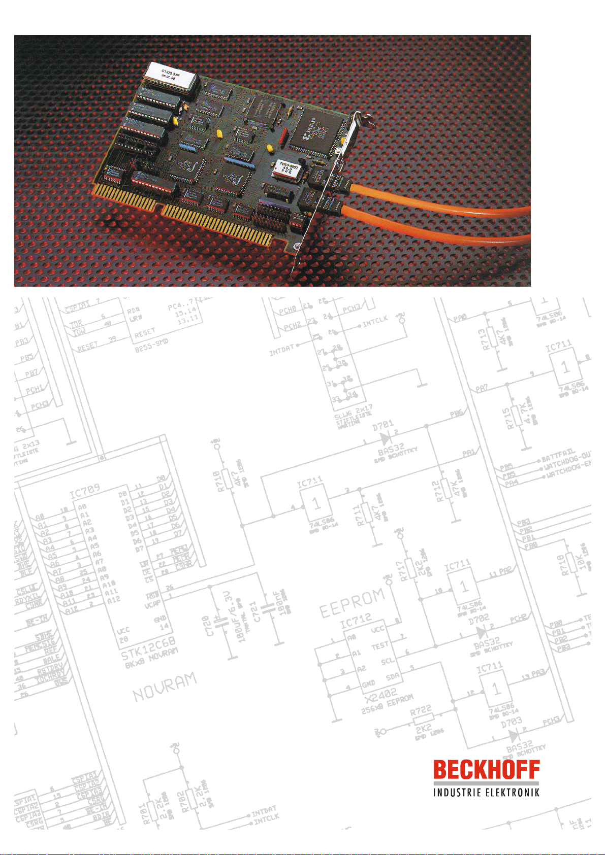
Beckhoff Lightbus - PC
interface card
C1220
Technical hardware description
Version 4.0
Page 2

Eiserstraße 5 / D-33415 Verl / Telefon 05246/963-0 / Telefax 05246/963-149
Contents 2
Contents
1. Beckhoff Lightbus System Description 3
2. Hardware description of functions 6
3. Software description of functions 7
General 7
Description of the communication channels 9
Test and analysis functions 11
Fibre-optic reset 11
Code word 12
Software version 12
Evaluation of Parity Errors 12
Fibre-optic attenuation test 13
Count peripheral modules 14
Test peripheral module addresses 14
Continuous sending 14
Software-RESET 15
Fibre-optic fracture point test 15
Invalid function selection 15
Configuration 16
Reinitializing communication management 16
CDL communication 16
Freely programmable communication 18
Cyclic communication 19
Transmitting the interrupt mask 19
String Communication 21
General 21
String structure 21
Initialisation of string communication 22
Registration of a string slave 23
Structure of the buffer for string communication 24
Sending a string 24
Receiving a string 24
Slave to slave string communication 24
Register communication 24
Process image control functions 25
C1220 II/O Error Counter 27
4. Technical Data 28
5. Installation notes 29
Jumper configuration 29
Status display 30
Installation in the PC 30
Beckhoff Lightbus - PC interface card C1220
Page 3
Eiserstraße 5 / D-33415 Verl / Telefon 05246/963-0 / Telefax 05246/963-149
&RQWURO
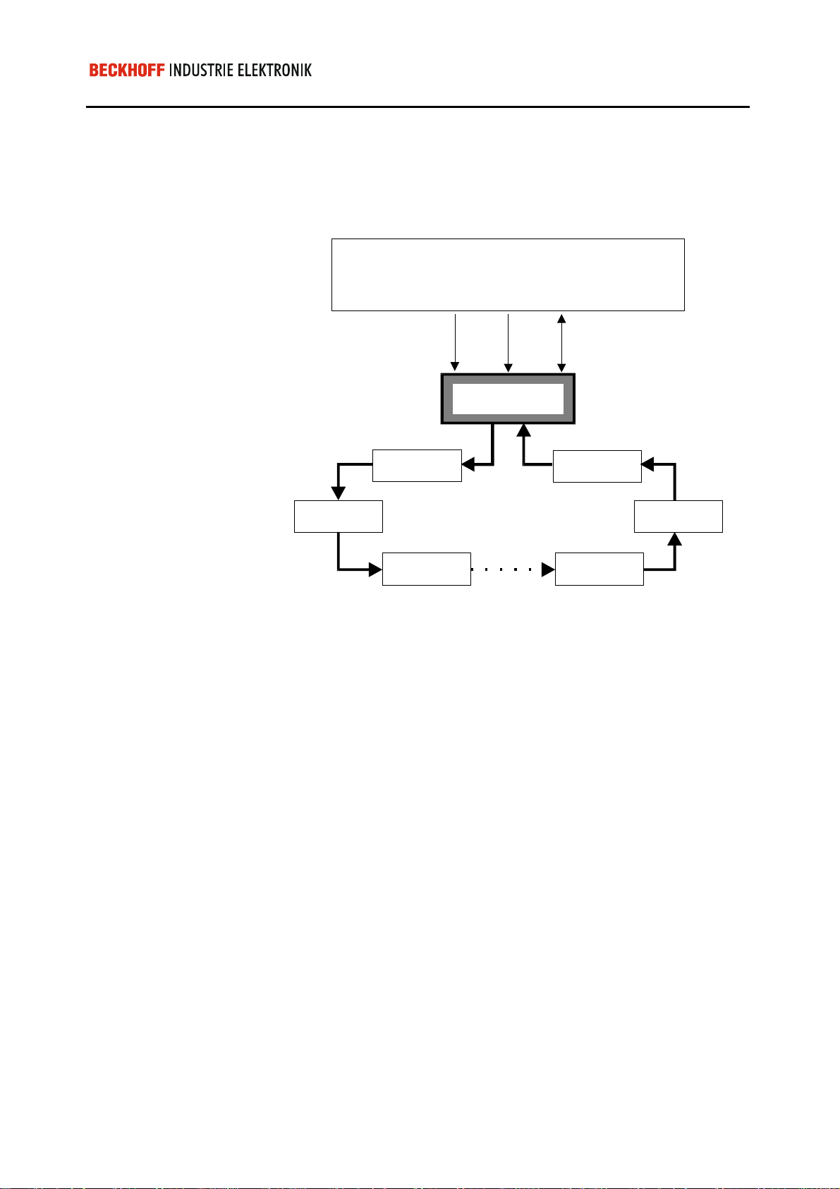
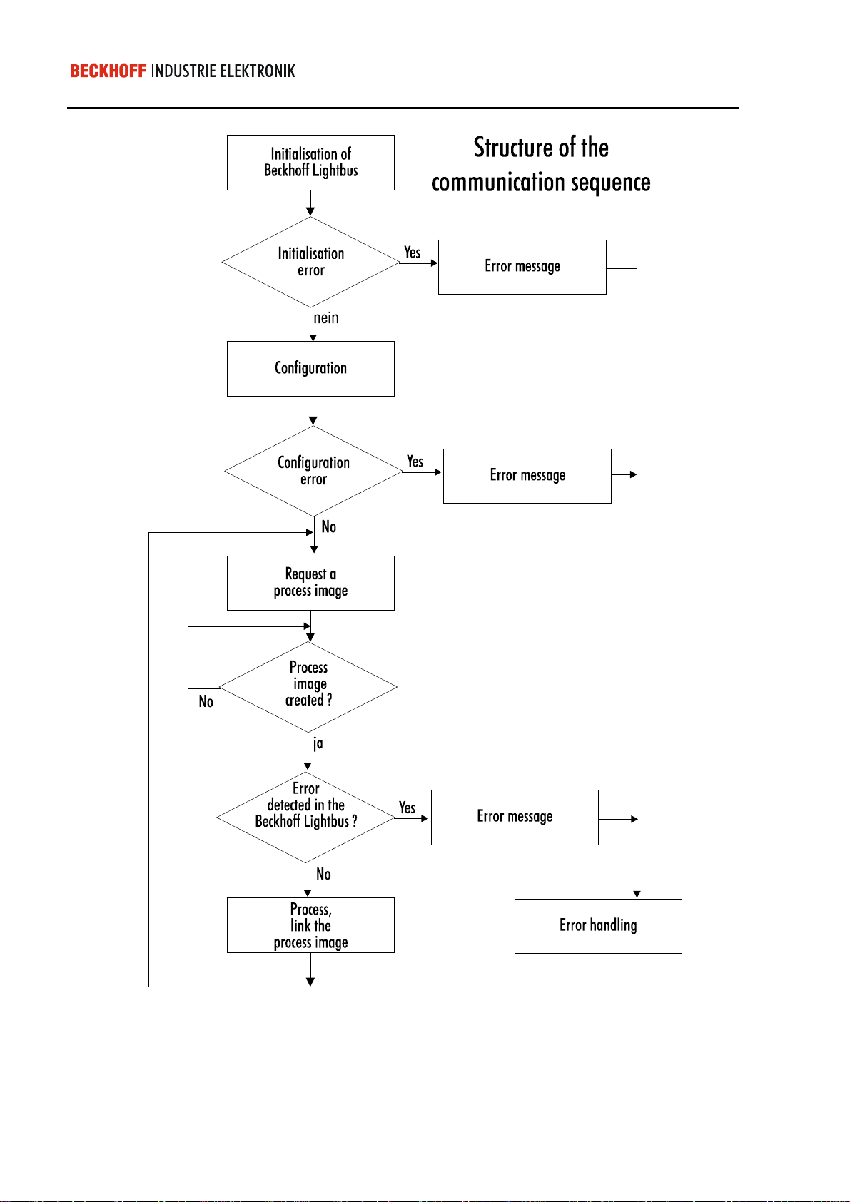
3 Beckhoff Lightbus System Description
Beckhoff Lightbus System Description
The Beckhoff Lightbus c onsists of an int elligent central m odule and a field
bus based on fibre-optic conductor.
Beckhoff Lightbus
+RVW V\VWHP
$GUHVVHV
'DWD
&HQWUDO PRGXOH
7HUPLQDOURZ
,2PRGXOH
%HFNKRII /LJKWEXV
7HUPLQDOURZ
,2PRGXOH
ILEH U RSWLF ULQJ
,2PRGXOH
The Beckhoff Lightb us is coupled to the host Syst em via a DPRAM, thus
guaranteeing fast and convenient communication.
Bus couplers for Beckhoff Bus terminals and diverse I/O modules are
available for processing the proces s image. M odules and bus couplers are
linked to one anoth er in a ring structure. Thanks to the use of fibre-optic
conductor, interferenc e sensitivity is low and the data tra nsfer rate of 2.5
Mbaud is high. Errors occ urring in the fibre-optic ring ar e detected by the
central module and are reported to the host system. Implemented ring
diagnostics functions enable swift error detection and remedying.
7HUPLQDOURZ
A communication protocol optimized for speed and simplicity has been
defined for data transfer between the central module and I/O modules.
Below, this communication protocol is also referred to as a telegram.
Communication on th e f ibre- o ptic r i ng is contr o ll ed by the central m odule. It
sends telegrams which pas s through the individual modules an d terminal
rows in the fibre-optic ring, and which are ultimately received again and
checked.
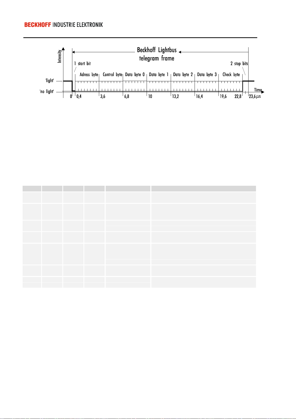
A telegram consists of the telegram frame and contents.
Beckhoff Lightbus - PC interface card C1220
Page 4
Eiserstraße 5 / D-33415 Verl / Telefon 05246/963-0 / Telefax 05246/963-149
Beckhoff Lightbus System Description 4
The telegram frame is required for serial, asynchronous data
communication and consists of 1 start bit, 6 CRC check bits and 2 stop
bits. The telegram frame is generated and checked by the hardware.
Software support is not necessary.
The telegram contents are essentially based on a byte organization.
AD0 - AD7 constitute t he so called address f ield. Up to 254 modules and
terminal rows can be addressed via this address field (the addresses 0x00
and 0x0ff are reserved).
CR0 - CR3 defines the telegram type. The following functions can be
defined in the telegram:
CR3 CR2 CR1 CR0 Function Description
0 0 0 0 READ The addressed module inserts the input
information in the data fields D0 - D3.
0 0 0 1 READ/WRITE The addressed module inserts the input
information in the data fields D0 - D3 and
accepts the output information.
0 0 1 0 ADDRESS
INITIALIZATION
0 0 1 1 RAM A special type of telegram for bus coupler
0 1 0 0 ADDRESS
CHECK AND
COUNT
COMMAND
1 0 0 1 LOW INTENSITY
COMMAND
1 0 1 1 BROADCAST
The addressed module accepts the contents of
D0 as the module address and sets D0 = 0.
BK2000
Every module that is passed through increments
the contents of D0 by 1. The addressed module
transfers the contents from D0 to D3.
The addressed module reduces the send
intensity by 20%.
A special type of telegram for bus coupler
BK2000
The bytes D0 - D3 conta in the actual user information. Processi ng of this
user information data is defined by the control field.
The last byte in the telegram contains 2 reserve bits and 6 bits for
generation of a CRC check sum. A Hamming distance of d=3 is ac hieved
with a length of the contents amounting to 50 bits.
Beckhoff Lightbus - PC interface card C1220
Page 5

Eiserstraße 5 / D-33415 Verl / Telefon 05246/963-0 / Telefax 05246/963-149
5 Beckhoff Lightbus System Description
The Beckhoff Lightb us consists of a p hysical ring whic h can be split into 8
logical rings for processing th e process im age. A log ical ring onl y operates
on selected modules and term inal rows that are defined by means of so
called Communication D escripti on Lists ( CDLs). Tr ansfer of the CDLs fr om
the host system to the central module will be discussed in further detail
later.
The process im age is made available to the host system via the DPRAM.
The DPRAM is split into three areas:-
- Data: Input, output and flags
- Communication: Initialization, test, analysis and configuration of the
Beckhoff Lightbus
- Process control: Updating of process images
To this end, the central module requires a 4 k byte area in the address
space of the host system.
Beckhoff Lightbus - PC interface card C1220
Page 6
Eiserstraße 5 / D-33415 Verl / Telefon 05246/963-0 / Telefax 05246/963-149
/LJKWEXV/&$
Hardware description of functions 6
Hardware description of functions
Lightbus PC interface card
C1220
PC control
&
%HFNKRII/LJKWEXV3&,QWHUIDFH
-
-
The Lightbus - PC interface C1220 is an intelligent Lightbus central
module.
As a plug-in ISA bus PC board, the C1220 link s the Beckhoff Lightbus to
the PC as the host system and is therefore a n impor tant component of the
PC control concept.
&
7;
5;
-
-
With the aid of the C1220 , fast processing of a process im age defined by
the sensors / actuators of the Beckhoff Lightbus is enabled.
Beckhoff Lightbus - PC interface card C1220
Page 7

Eiserstraße 5 / D-33415 Verl / Telefon 05246/963-0 / Telefax 05246/963-149
7 Software description of functions
Software description of functions
General
Memory breakdown of the
interface
Address area Function
0x0000 - 0x0BFF
0x0C00 - 0x0CFF
0x0D00 - 0x0DFF
0x0E00 - 0x0FEF
0x0FF0 - 0x0FFF
Data area
(Inputs, outputs, flags)
3 kbytes
Handshake channel 0: PC -> C1220
(configuration, test, analyse)
Handshake channel 1: C1220 -> PC
(configuration, test, analyse)
reserved
GCB (General control block)
The interface between the PC bus and the C1220 module enables the
following functions:
- Data transfer of the process image
- Test and analysis functions for the II/O system
- Configuration
- Control of process images
By way of the communication channels, the Beckhoff Lightbus can be
configured by means of four functions. In do ing so, the inputs / outp uts of
the decentralized I/O modules are assigned to the addresses in the
DPRAM. A total of nine further functions can also be requested via the
communication channels for test and analysis functions.
The data areas for the CDLs are located in the bottom 3 kbyte area that the
C1220 module occupies in the address space. The request to update the
process image is realized by setting a b it in the request mask of the GCB
(General Control Block). The ready message for this request is obtained
from the corresponding bit in the ready mask of the GCB.
Beckhoff Lightbus - PC interface card C1220
Page 8
Eiserstraße 5 / D-33415 Verl / Telefon 05246/963-0 / Telefax 05246/963-149
Software description of functions 8
Beckhoff Lightbus - PC interface card C1220
Page 9

Eiserstraße 5 / D-33415 Verl / Telefon 05246/963-0 / Telefax 05246/963-149
9 Software description of functions
Description of the communication channels
Two channels are config ured for communic ation between the PC bus a nd
C1220. Each channel embraces 255 bytes. The PC writes the data
required for requesting the required function into the channel 0 and then
outputs a DV (Data Val id). After acceptance of the data, the C122 0 module
outputs the ‘Quit’ signal. The PC withdraws the ‘DV’ and a new
communication can be commenced as soon as the ‘Quit' signal is 0.
Channel 0 from the PC b us to the C1220 provides the address area from
0xC01 to 0xCFF for the data. DV is the MSB of the ad dr es s 0x C00. 'Qu it' is
the second highest bit of the address 0xD00.
Communication channel 0:
Communication channel 1:
Addresses of the
Komunikationskanäle
Byte 0
0xC00
Byte 1 ................ Byte 254 Byte 255
0xCFF
Channel 1 from the C1220 module to the PC bus provides the address
area from 0xD01 to 0xDFF for the data. DV is the MSB of the address
0xD00. 'Quit' is the second highest bit of the address 0xC00.
Byte 0
0xD00
Address Address bits Contents
0xC00
0xC00
0xC01
0xC02
0xC03
0xCnn
0xCFF
0xD00
0xD00
0xD01
Byte 1 ................ Byte 254 Byte 255
7 6 5 4 3 2 1 0
1 0 0 0 0 0 0 0 ’Data Valid’ for
Channel 0
(in the case of PC -> C1220 data
transfer)
0 1 0 0 0 0 0 0 ’Quit’ for Channel 1
(in the case of C1220 -> PC data
transfer)
Length (von 2 bis 0xFE)
Functionsnummer
(1 bis 0xFE)
Argument 0
..
..
1 x 0 0 0 0 0 0 ’Data Valid’ for
x 1 0 0 0 0 0 0 ’Quit’ for Channel 0
..
Argument n
..
..
Channel 1
(in the case of C1220 -> PC data
transfer)
(in the case of PC -> C1220 data
transfer)
Length (from 2 to 0xFE)
0xDFF
Beckhoff Lightbus - PC interface card C1220
Page 10

Eiserstraße 5 / D-33415 Verl / Telefon 05246/963-0 / Telefax 05246/963-149
Software description of functions 10
Address Address bits Contents
0xD02
0xD03
..
0xDnn
..
0xDFF
Function number
(1 to 0xFF)
Argument 0
..
Argument n
..
..
Sequence of a handshake
Existing functions
:0C00
:0D00
:0C00
:0D00
. . .
:0D00
:0C00
:0D00
:0C00
No. Function
0x01
0x02
0x03
0x04
0x05
0x06
0x07
0x08
0x09
0x0a
0x0b
0x0c
0x0d
0x0e
0x0f
0x10
0x11
0x12
0x13
0x14
0x15 Log in string node ???
0xff
0x80 Data Valid Host = 1
0x40 DataQuit C1220 = 1
0x00 Data Valid Host = 0
0x00 Data Quit C1220 = 0
Function execution
0x80 Data Valid C1220 = 1
0x40 Data Quit Host = 1
0x00 Data Valid C1220 = 0
0x00 Data Quit Host = 0
FIBRE-OPTIC RESET
Query code word
Query software version
Query parity error
Attenuation test
Count modules
Address test
Continuous sending
Software RESET
Fracture point test
Transfer freely programmable communication
Reinitialize CDL management
reserved
reserved
Interrupt mask
Transfer CDL configuration
reserved
Cyclic communication
reserved
Initialize string communication
Invalid function request
Beckhoff Lightbus - PC interface card C1220
Page 11

Eiserstraße 5 / D-33415 Verl / Telefon 05246/963-0 / Telefax 05246/963-149
11 Software description of functions
A function request is composed of a length entry, a func tion number and
the function argum ents. The length entr y refers to the num ber of follo wing
bytes:
Byte ’Length’ + Byte ’Function number’ + Number of Bytes ’Argument
0’ to ’Argument n’
Test and analysis functions
Fibre-optic reset
The fibre-optic ring can be rein iti al i zed b y means of th is f unc tion. Within the
scope of initialization, the number of modules in the ring is defined, the
module addresses are distribu ted and tested and the ring is chec ked with
regard to its attenuation reserve. Any existing fracture point is also
detected and located.
Request
Reply
ArgumentChannel Length Function
0 1 2
02 0x01
05 0x01 00 00 nn Funct ion corr ect ly ex ecuted
05 0x01 01 01 00 Maximum number of send repetitions
05 0x01 01 02 00 No address setting possible
05 0x01 0a 01 nn Fracture point before nn-th module
05 0x01 0a 01 ff Fracture point cannot be located
05 0x01 07 01 nn Test addresses:
05 0x01 05 02 00 Attenuation test:
05 0x01 05 03 nn Attenuation test:
05 0x01 05 04 nn Attenuation test:
05 0x01 05 05 nn Attenuation test
05 0x01 05 06 nn Attenuation test :
05 0x01 05 07 nn Attenuation test :
Comment
(nn modules in the fibre-optic ring)
exceeded
before the receiver input of the C1220
(Fracture point before receiver input)
Address error (module nn)
Error with high intensity
Switch error with low intensity
(module nn)
Error with data pattern 1
(pattern 00)(module nn)
Error with data pattern 2
(pattern FF) (module nn)
Error with data pattern 3
(pattern AA) (module nn)
Switch error with high intensity
(module nn)
The number of m odules in the r ing is co mm unicated if the ring is initiali zed
without errors. If an error should have occ urred, the error type (see table)
and the module address where the error occurred are returned.
Beckhoff Lightbus - PC interface card C1220
Page 12
Eiserstraße 5 / D-33415 Verl / Telefon 05246/963-0 / Telefax 05246/963-149
Software description of functions 12
Code word
The C1220 outputs the code word after every reset of communication
channel 1. Here, this takes place without setting the Data Valid bit. The
purpose of the code word is t o inf orm the PC that the C1220 int erf ace card
is initialized and read y. The code wor d can also be quer ied at any tim e by
way of the 0x02 function.
Request
Reply
Request
Reply
ArgumentChannel Length Function
0 1 2
02 0x02
04 0x02 fe af Correct code word
Comment
Software version
The version of the EPROM firmware can be queried b y way of the 0x03
function.
ArgumentChannel Length Function
0 1 2
02 0x03
04 0x03 xx xx Version xxxx
Comment
Evaluation of Parity Errors
If the peripheral modules are fitted with type 132 or BX415
(BK2000) SPROMs , it is possible to localise the s ources of parity error s.
The master card produc es a “parity error counter” (8 bits wide) for every
module present. This counter works without overflow.
The counter can be read by means of function 04.
Request
Reply
Request
Reply
Request
Reply
ArgumentChannel Length Function
0 ...128
03 0x04 00 Transmit counter for modules 0 - 127
130 0x04 n ...y
03 0x04 01 Transmit counter for modules 128 -255
130 0x04 n ...y
03 0x04 02 Reset counter
02 0x04 Counter reset
Comment
Counter for modules 0 – 127
(0 = non-localisable parity error)
Counter for modules 128 -255
Beckhoff Lightbus - PC interface card C1220
Page 13

Eiserstraße 5 / D-33415 Verl / Telefon 05246/963-0 / Telefax 05246/963-149
13 Software description of functions
Fibre-optic attenuation test
The attenuation reserve of the fibre-optic ring can be tested with this
function. In this test, all leaks of the fibre-optic r ing are partially operated
with approximately 80% of the norm al transmission intensity and extreme
test telegrams. This test can be run f or all modules or for onl y one sel ected
module (see table). The C1220 can be tested separately via the module
address 0.
The table shows the function requests and the possible
acknowledgements.
Request
Reply
ArgumentChannel Length Function
0 1 2
04 0x05 00 00 Test all modules
04 0x05 01 nn Test module nn
04 0x05 00 00 Ring has adequate attenuation reserve
04 0x05 02 00 Error with high intensity
04 0x05 03 nn Switch error with low intensity (module nn)
04 0x05 04 nn Error with data pattern 1
04 0x05 05 nn Error with data pattern 2
04 0x05 06 nn Error with data pattern 3
04 0x05 07 nn Switch error with high intensity (module nn)
04 0x05 09 00 Continuous sending function active
Comment
(pattern 00)(module nn)
(pattern FF)(module nn)
(Pattern AA)(module nn)
"Error with high intensity" means that the ring already has an excessive
attenuation during normal operation or that there may be a fracture point.
"Switch error with l ow intensit y" means that the trans where intensit y of the
module concerned cannot be reduced.
"Error with data pattern xx" indicates that the fibre-optic ring after the
specified module has an excessive a ttenuation. It is never theless possib le
to operate the system, with the res u lt t hat t his malfunction can be r emedied
at a suitable point in time.
"Switch error with high intensity" means that the spec ified module can no
longer be switched back to the full transwhere power.
Beckhoff Lightbus - PC interface card C1220
Page 14

Eiserstraße 5 / D-33415 Verl / Telefon 05246/963-0 / Telefax 05246/963-149
Software description of functions 14
Count peripheral modules
The number of modules in the ring can be defined with this function.
Request
Reply
Request
Reply
ArgumentChannel Length Function
0 1 2
02 0x06
04 0x06 00 nn Count modules:
04 0x06 01 00 Count modules:
Comment
nn modules in the ring
Ring interrupted
Test peripheral module addresses
By means of this function, a check is made as to whether the m odules are
still keeping to the addresses they received on initialization.
ArgumentChannel Length Function
0 1 2
02 0x07
04 0x07 00 00 Addresses correct
04 0x07 01 nn Error at address nn
To guarantee maximum operating re liability, during normal operation this
function can also be run cyclically in the background. In doing so, the
function is activated by setting a bit in th e GCB. In the ev ent of an error, a
message is sent to the PC via the GCB.
Comment
Request
Reply
Continuous sending
The continuous sending function only controls the ’Cycle’ LEDs on the
modules to determine how many modules are still connected to the
transwhere output of the C1220. This function should onl y be activated if
the 0x0a (Fracture point test) does not ret urn a satisfactor y result. On the
software end, continuous sending can only be stopped by a RESET.
ArgumentChannel Length Function
0 1 2
02 0x08
03 0x08 01 Continuous sending can be stopped by
Comment
RESET
Beckhoff Lightbus - PC interface card C1220
Page 15

Eiserstraße 5 / D-33415 Verl / Telefon 05246/963-0 / Telefax 05246/963-149
15 Software description of functions
Software-RESET
The C1220 can be reset by means of this f unction. Bes ides reinitiali zation
of the fibre-optic ring, the controller and the dual ported RAM are also
reinitialized. Completion of RESET is acknowledged by the code word
(without Data Valid).
Request
Reply
Request
Reply
ArgumentChannel Length Function
0 1 2
02 0x09
04 0x02 fe af
Comment
Fibre-optic fracture point test
A fracture point in the fibre-optic ring can be localized by this function.
Depending on the resu lt, the test s pecifies the number of boxes in t he ring
or the location of the fracture point.
ArgumentChannel Length Function
0 1 2
02 0x0a
04 0x0a 00 nn No fracture point,
04 0x0a 01 nn Fracture point before nn th-module before
04 0x0a 01 ff Fracture point cannot be located (fracture
If the fracture point shoul d be specified as not being cap able of location, it
is probably located between t he last module and the receive input of the
C1220.
Comment
nn modules in the ring
the receiver input of the C1220
point before receiver input)
Invalid function selection
If a function is reques ted via handshake c hanne l 0 that is r es erv ed or is n ot
available, it is acknowledged with the function 0x0ff, which contains the
invalid function number as Argument 0.
Example:
Request
Reply
Beckhoff Lightbus - PC interface card C1220
03 0x04 01
03 0x0ff 04
ArgumentChannel Length Function
0 1 2
Comment
Request function 4
(reserved)
Page 16

Eiserstraße 5 / D-33415 Verl / Telefon 05246/963-0 / Telefax 05246/963-149
Software description of functions 16
Configuration
A total of four f unctions is available for description of the conf iguration, of
affiliation of the i nputs or outputs in t he Bec k hoff Light bus to the ad dres ses
in the DPRAM, and the affiliations of the modules to th e processor gr oups.
The configuration is also transwhereted via the handshake channels.
The management part of the com m unication func tions m ust be rei nitiali zed
at the start of a new configuration.
Each of the maximum number of 8 communication functions can be
optionally configured as CDL communication or as freely programmable
communication.
A further function configures the interrupt channels for the addressindependent interrupts.
Reinitializing communication management
Both the CDLs and also the f reel y program mable comm unication f unctions
consist of two parts , a d ata p art and a management part. The management
parts must be reset before new configurations are communicated. The
management parts of all 8 comm unication funct ions are res et by activat ing
the function 0ch.
Request
Reply
0 1 2
02 0x0c
03 0x0c 00
CDL communication
A CDL is generated for each group of modules whose process image is to
updated jointly. This CDL is composed of so-called descriptors. A
descriptor describes a telegram for a module and is structured as follows:
Bytes Contents
0,1
2,3
4,5
6,7
8,9
10,11
12,13
14,15
16,17
18,19
ArgumentChannel Length Function
II/O module address (1 - FE)
Control Word :
0x0000: READ
0x0010: READ/WRITE
0x0030: RAM
0x00B0: BROADCAST
Pointer to byte for output in D0 of a message
Pointer to byte for output in D1 of a message
Pointer to byte for output in D2 of a message
Pointer to byte for output in D3 of a message
Pointer to byte for input in D0 of a message
Pointer to byte for input in D1 of a message
Pointer to byte for input in D2 of a message
Pointer to byte for input in D3 of a message
Comment
Beckhoff Lightbus - PC interface card C1220
Page 17

Eiserstraße 5 / D-33415 Verl / Telefon 05246/963-0 / Telefax 05246/963-149
17 Software description of functions
Example of a descriptor:
Telegram to I/O module 1 : D0 - D2 Outputs
D3 Input
The data for the output in D0 - D2 is fetched from the addresses 0x400,
0x302 and 0x210 in the DPRAM.
The data item for the input in D3 is stored at the address 0x30 in the
DPRAM.
Bytes Contents
0,1
2,3
4,5
6,7
8,9
10,11
12,13
14,15
16,17
18,19
0x01, 0x00
0x10, 0x00
0x00, 0x04
0x02, 0x03
0x10, 0x02
0xff, 0xff
0xff, 0xff
0xff, 0xff
0xff, 0xff
0x30, 0x00
Constants
Request
Reply
At the DPRAM adress offset 0xEF0 - 0xFEF th e c onstan ts 0x 00 - 0x FF can
be found. To insert cons t ants i nto the dat a bytes of the Lightbus telegrams,
you just have to set the descriptor to the corresponding offset.
The above-mentioned CDLs are split into parts so they can be transf erred
via the handshake c hannel 0. In doing so, the information for a message
must not be split. Transfer can be activated with the function 0x10.
ArgumentChannel Length Function blank
0 1 2 ... n
nn 0x10 00 aa bb db1,0 dbn,19
ArgumentChannel Length Function
0 1 2
04 0x10 aa 00 o.k.
04 0x10 aa 01 Error in CDL data
04 0x10 aa 02 CDL overflow
04 0x10 aa 03 Invalid descriptor length
Comment
(e.g.: Pointer not in the DPRAM’s data area)
Beckhoff Lightbus - PC interface card C1220
Page 18

Eiserstraße 5 / D-33415 Verl / Telefon 05246/963-0 / Telefax 05246/963-149
Software description of functions 18
aa
where:
db1,0
dbn,19
00 = start of a CDL transfer
01 = further descriptors of the same CDL
02 = last transfer of the same CDL
bb
Process image No bb ( 1 ... 8)
Descriptor 1, byte 0 of a CDL
...
...
Descriptor n, byte 19 of a CDL (n = 2 ... 13 )
The module address, the contr ol byte and t he pointers to the data b ytes of
a message are transfer red in Intel notation (least significan t byte at least
significant address).If a pointer to a data byte in a m essage is not needed,
a dummy pointer 0x0ffff
must be entered here.
The arguments 2 - n can be dropped when CDL transfer is concluded
(Argument aa = 02).
Freely programmable communication
where:
Request
With this mode of communication, telegrams are stored as from a
previously defined address in the DPRAM and are com bined in a process
image. The input data is transferred to the PC s ystem as from an address
that is also defined beforehand.
With this function, the parameters necessary for initialization are
transferred to the C1220.
ArgumentChannel Length Function blank
0 1 2 3
09 0x0b 00 pan at oa 0,1 ia 0,1
Channel Length Function Argument 0 Comment
Reply
pan
oa 0,1
ia 0,1
03 0x0b 00 ok
03 0x0b 01 Error
Process image number
at
Number of telegrams
Base address of output area
Base address of input area
The base address of the output area defines the memory area in the
DPRAM as from which the user-def ined telegram s are stored. In doi ng so,
only the address byte, the control byte and four data bytes are entered.
The check byte is not entered. This entry is made internally by the
controller.
As from the base address for the input ar ea, t he C122 0 e nters 0x00 f or the
address and control byte and the input data is stored.
Beckhoff Lightbus - PC interface card C1220
Page 19

Eiserstraße 5 / D-33415 Verl / Telefon 05246/963-0 / Telefax 05246/963-149
19 Software description of functions
Example:
Initialization of communication 3 as fr ee communication with 2 tele grams.
The base address f or the output area is 0x400, and the base address f or
the input area is 0x210.
ArgumentChannel Length Function blank
0 1 2 3
where:
Request
09 0x0b 00 03 02 00,04 10,02
Channel Length Function Argument 0 Comment
Reply
03 0x0b 00 ok
By means of this struc ture it is also possibl e to m odif y the m odule address
and the control byte duri ng the run time. One restr iction here, however, is
that this must not take place while communication is active.
Cyclic communication
With the function 0x 12, it is poss ible to trigger communicatio n cyclicall y by
the central module. In doing so, the otherwise necessary Handshake by
way of the GCB is dropped.
Channel Length Function Argument 1 Argument2
Request
Channel Length Function Argument 0 Comment
Reply
pan
04 0x12 k pan
03 0x12 00 ok
03 0x12 01 Error
Process image number
k
Status
0 = Communication passive
1 = Communication active
In this mode of communication, however, only byte-oriented I/O f unctions
should be executed because the timing behavior is no longer deterministic.
Transmitting the interrupt mask
The module C1220 features 4 interrupt channels through which the
address-independent int errupts are transferred to the PC. Trans fer to the
PC is realized via the GCB.
The address-independent interrupts can be generated by the peripheral
modules. In doing so, they are inserted in the interrupt field of the control
byte.
The function 0x0f is used to communicate to the module C1220 which
interrupt channels are to be activated and which interrupt criteria are to
lead to interrupt transmission to the PC.
Beckhoff Lightbus - PC interface card C1220
Page 20

Eiserstraße 5 / D-33415 Verl / Telefon 05246/963-0 / Telefax 05246/963-149
Software description of functions 20
ArgumentChannel Length Function
0 1 2 3 4
Request
Reply
07 0x0f 0m Criterion
for
interrupt
channel 0
03 0x0f 0m
The LOW nibble in the argument 0 specifies which of the 4 possible
interrupt channels is to be enabled.
Example: m = 0x00 all interrupt channels disabled (Default)
m = 0x01 Interrupt channel 0 enabled
m = 0x06 Interrupt channels 1 and 2 enabled
m = 0x0f Interrupt channels 0, 1, 2 and 3 enabled
Each interrupt channel can be characterized by way of a criterion.
The following criteria can be selected:
Criterion Interrupt-Channel
no Interrupt
Interrupt on positive edge
Interrupt on negative edge
Interrupt on edge change
Criterion
for
interrupt
channel 1
0
1
2
3
Criterion
for
interrupt
channel 2
(0,1,2,3)
Criterion
for
interrupt
channel 3
The respective criter ia are assign ed to th e inter rupt c hanne ls b y way of the
arguments 1 to 4.
Example:
Request
Interrupt enabling for channels 2 and 3
Interrupt criterion for interrupt channel 0
no interrupt transfer
Interrupt criterion for interrupt channel 1
no interrupt transfer
Interrupt criterion for interrupt channel 2
Interrupt transfer with a positive edge
07 0x0f 0x0c 00 00 01 03
ArgumentChannel Length Function
0 1 2 3 4
Interrupt criterion for interrupt channel 3
Interrupt transfer with an edge change
Beckhoff Lightbus - PC interface card C1220
Page 21

Eiserstraße 5 / D-33415 Verl / Telefon 05246/963-0 / Telefax 05246/963-149
21 Software description of functions
Before the interrupts are activated, a read access m ust take place to the
cell IRQ inputs in the General Control Block (see Chapter 3.5).
String Communication
General
String communication is used for packet oriented data exchange with
peripheral modules. Usually, parameter data is exchanged with the
modules (e.g. parameterisation of a BK2000 by register interface).
This type of communication also permits slave to s lave comm unication, as
well as communication between m aster and slave. The master card then
functions simply as a relay station.
The following resources are required to carry out string communication:
– 2 CDLs for sending or receiving the strings.
– 2 buffers in DPRAM for string storage, the buffer size being
parameterisable.
String structure
A data string consis ts of a four-byte string hea der and a string data area.
The header contains th e necessary routin g information, an d the data ar ea
contains the user data itself. T he entire string c an have a maximum length
of 255 bytes.
A string has the following structure:
Offset Description
0x00
0x01
0x02
0x03
0x04
0xFF
Address of the sender (TX)
Address of the receiver (RX)
Channel / priority (only relevant to the BK2000)
String length
...
String data
Beckhoff Lightbus - PC interface card C1220
Page 22

Eiserstraße 5 / D-33415 Verl / Telefon 05246/963-0 / Telefax 05246/963-149
Software description of functions 22
Initialisation of string communication
String comm unication is i nitialis ed via the hands hake chann el wit h functio n
0x14.
ArgumentChannel Length Function
0 1 2 3
Request
Request
Reply
0x0A 0x14
0x03 0x14
0x03 0x14 0x00 No error.
Continuation of the table
Init
StringComm.
(0x01)
Deinit
StringComm.
(0x00)
0x01 Wrong CDL number for string transmit CDL.
0x02
0x03 Wrong CDL number for string receive CDL.
0x04
0x05
0x06
4 5 6 7
Offset string transmit buffer Offset string receive buffer
Deactivation of string communication also deactivates all the string
slaves.
No error.
Wrong CDL number for string transmit CDL.
String transmit CDL already occupied.
Wrong CDL number for string receive CDL.
String receive CDL already occupied.
Wrong transmit string base address.
Wrong receive string base address.
CDL no.
string Trns
Deactivation of string communication also
deactivates all the string slaves.
String transmit CDL already occupied.
String receive CDL already occupied.
Wrong transmit string base address.
Wrong receive string base address.
CDL no.
string receive
Argument
Max. string
length
Beckhoff Lightbus - PC interface card C1220
Page 23

Eiserstraße 5 / D-33415 Verl / Telefon 05246/963-0 / Telefax 05246/963-149
23 Software description of functions
Registration of a string slave
Before string communication with a string slave is possible, it must be
registered with the master card.
This is done by means of function 0x15.
ArgumentChannel Length Function
0 1 2
Request
Request
Reply
0x0A 0x15 SubFnc Physical
slave
address
0x03 0x15 01 Mn xy Enter string slave without
02 Mn Xy Enter string slave with
03 Mn Xy
04 Mn xy
00 Mn xy Deactivate string slave.
0x03 0x15 0x00 No error.
0x01
0x02
0x03
Wrong slave address.
Error during string reset at the slave.
Optical fibre error.
Logical
slave
address
string reset.
string reset.
Enter string slave without
string reset. Transmission
of the string without
triggering an interrupt at
the slave.
Enter string slave with
string reset. Transmission
of the string without
triggering an interrupt at
the slave.
Before communication with a slave is possible, a string reset must be
successfully carried out. The string reset at a slave synchronises the
handshake bits bet ween m aster and slav e. Ther e are two wa ys to trigger a
string reset:
- The reset is initiated by the master when the slave is registered.
- The reset is initiated at a later tim e b y the slav e (see a lso “T riggering a
String Reset by the Slave”).
A string slave is only addressed for string transmission by means of its
logical slave addres s (al though the lo gica l addres s can b e the sam e as the
physical address).
Beckhoff Lightbus - PC interface card C1220
Page 24
Eiserstraße 5 / D-33415 Verl / Telefon 05246/963-0 / Telefax 05246/963-149
Software description of functions 24
Structure of the buffer for string communication
Transmit / receive buffer Description
0x00.0
0x00.1 - 0x00.7
0x01
0x02
0x03
0x04
0x05
0x06 - 0xFF
Active flag
Error field 0x00: String transmitted without error.
0x04: Optical fibre error.
0x08: String slave not initialised.
0x10: String slave not yet ready for
communication.
0x20: Timeout during string transmission.
0x40: String length error.
Empty
Address of the sender (TX)
Address of the receiver (RX)
Channel / priority
String length
String data
Sending a string
To send a string to a s tring slave, the string data (he ader and user data)
are placed in the C1220’s transm it buffer. If the active flag is now set, the
master card is induced to send the string. Once this has occurred, the
master card now resets t he active f lag. If an y error has occ urred d uring the
string transmission, this is indicated in the error field.
Receiving a string
If a string is recei ved fr om a string slave, it is placed in the C1220’s r ecei ve
buffer, and the active flag is set. As long as a s tring tha t has been rec eive d
has not been acknowledg ed by resetting the active flag, no furth er string
will be fetched from a string slave.
Slave to slave string communication
Slave to slave communication (received string has RX not e qual to “0”) is
processed entirely by the master card.
Register communication
String communication can b e use d to ac cess the regis ter inter fac e of a b us
coupler or of a terminal in a simple manner.
To trigger register comm unication, channel 8 must sim ply be entered into
the string header. In the string data area an additional header, 6 bytes
large, is necessary.
High Byte Low Byte I/O
Address
127
Register data --
5 User data
Number of words Register (base) 4
R/W Table Terminal number 3 Header for register communication
Message Ident 2
Size Priority 8 1
RX_address TX_address 0 Header for string communication
Beckhoff Lightbus - PC interface card C1220
Page 25

Eiserstraße 5 / D-33415 Verl / Telefon 05246/963-0 / Telefax 05246/963-149
25 Software description of functions
Process image control functions
The General Control Block serves to control and check updating of the
individual process images. When a bit is set in the request mask the
corresponding process image is updated and is reported as com plete via
the ready mask. Af ter the c om plete m essage, the bit fir st has t o be de let ed
from the request mask before communication can be restarted. It is
possible to interrupt updating of a process image. If the request by a
higher-priority update is triggered during an ongoing process updating in
the request mask, the current operation is interrupted.
The corresponding b its are set in the error m ask if errors in the fibre-optic
ring are to be detected during normal operation.
General Control Block
Request mask:
Adress Contents Comment
0x0FFF
0x0FFE
0x0FFD
0x0FFC
0x0FFB
0x0FFA
0x0FF9
0x0FF8
0x0FF7
0x0FF6
0x0FF5
0x0FF4
0x0FF3
0x0FF2
0x0FF1
0x0FF0
Request mask
IRQ outputs
Ready mask
IRQ inputs
reserved
Error-Mask
Control-Mask
- reserved
- reserved
- reserved
Firmware Revision
Fimrware Release
- reserved
- reserved
- reserved
- reserved
P7 P0
high <= Priority <= low
Ready mask:
P7 P0
where: P7 => Process 08
...
P0 => Process 01
Error mask:
E7 E1 E0
E0 set = general fibre-optic error
E1 set = Address error in resident address check
E7 set = CPU error in the C1220
IRQ output:
Beckhoff Lightbus - PC interface card C1220
- - - - IO3 IO2 IO1 IO0
Page 26

Eiserstraße 5 / D-33415 Verl / Telefon 05246/963-0 / Telefax 05246/963-149
Software description of functions 26
If the PC modifies this mask, it is inserted into the interrupt fields of the
next telegrams. The nibble is inserted into the interrupt field until it is
withdrawn again by the PC.
IRQ inputs:
Control mask:
- - - - II3 II2 II1 II0
If an address-independent interrupt is generated by an I/O module, it is
transferred to the PC v ia this mask provi ded it is enabled by the interrupt
mask.
Pending interrupts ar e buf f er ed b y the C 12 20, i.e. only ever one interru pt is
transferred the PC via the GCB. Any other pending interrupt is not
transferred until this one has been recognized by the PC.
------C1C0
Bit C0 can be used to allow the PC to s witch off the reside nt address test,
or to reactivate it. In order to be able to localise par ity errors, the address
check must be active.
C0 set : Address test active.
C1 reset : Address test active even with optical fibre errors.
C0 is set by default.
Beckhoff Lightbus - PC interface card C1220
Page 27

Eiserstraße 5 / D-33415 Verl / Telefon 05246/963-0 / Telefax 05246/963-149
27 Software description of functions
C1220 II/O Error Counter
The C1220 has several counters to register II/O problem s. The counters
are stored in the DPRAM from off set 0xEE0, as 16-bit values. There is no
overflow processing, and no erasure of the counters by the C1220.
The counter which registers the errors of the internal address check
(0xEEA) is designed as an 8-bit counter , and does not incr ement the total
error.
DPRAM-Offset Meaning Function
0xEE0
0xEE2
0xEE4
0xEE6
0xEE8
-------------------0xEEA
0xEEC
Total error Delivers the number of error handing operations as the sum total of
the individual error triggers (following)
Error in receiver 1 Address and/or control unequal to transmitted bytes
Error in receiver 2 Address and/or control unequal to transmitted bytes
Timeout error Timeout in telegram reception
Parity error Telegram received with CRC error
----------------------------- --------------------------------------------------------------------------------------
Error in internal address
check
Module address in case
of internal address
check error
When this counter is incremented an address check and count
telegram with logically false content ( AD <> D3 ) is received.
If bit 1 is set in the C1220 error mask, this cell contains the module
address of the box which caused the error.
Beckhoff Lightbus - PC interface card C1220
Page 28
Eiserstraße 5 / D-33415 Verl / Telefon 05246/963-0 / Telefax 05246/963-149
Technical Data 28
Technical Data
Interface processor Siemens SAB 80C166-S
Data connection Beckhoff Lightbus
Data transfer rate 2,5 MBaud, 32 Bits of user information in
25µsec
Supply voltage 5 V
Current consumption 800 mA
Dimensions 161mm x 107mm
&
%HFNKRII/LJKWEXV3&,QWHUIDFH
&
/LJKWEXV/&$
/('581
/('&38(UURU
/('/LJKWEXV(UURU
-
-
7;
5;
-
-
Beckhoff Lightbus - PC interface card C1220
Page 29

Eiserstraße 5 / D-33415 Verl / Telefon 05246/963-0 / Telefax 05246/963-149
29 Installation notes
Installation notes
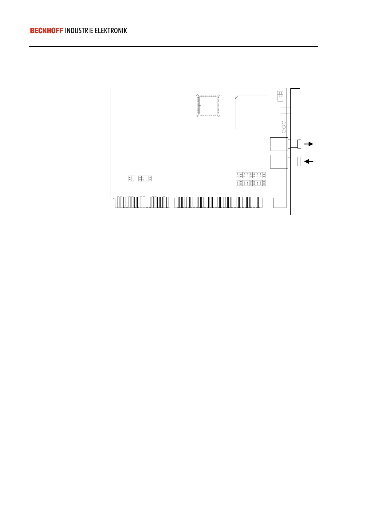
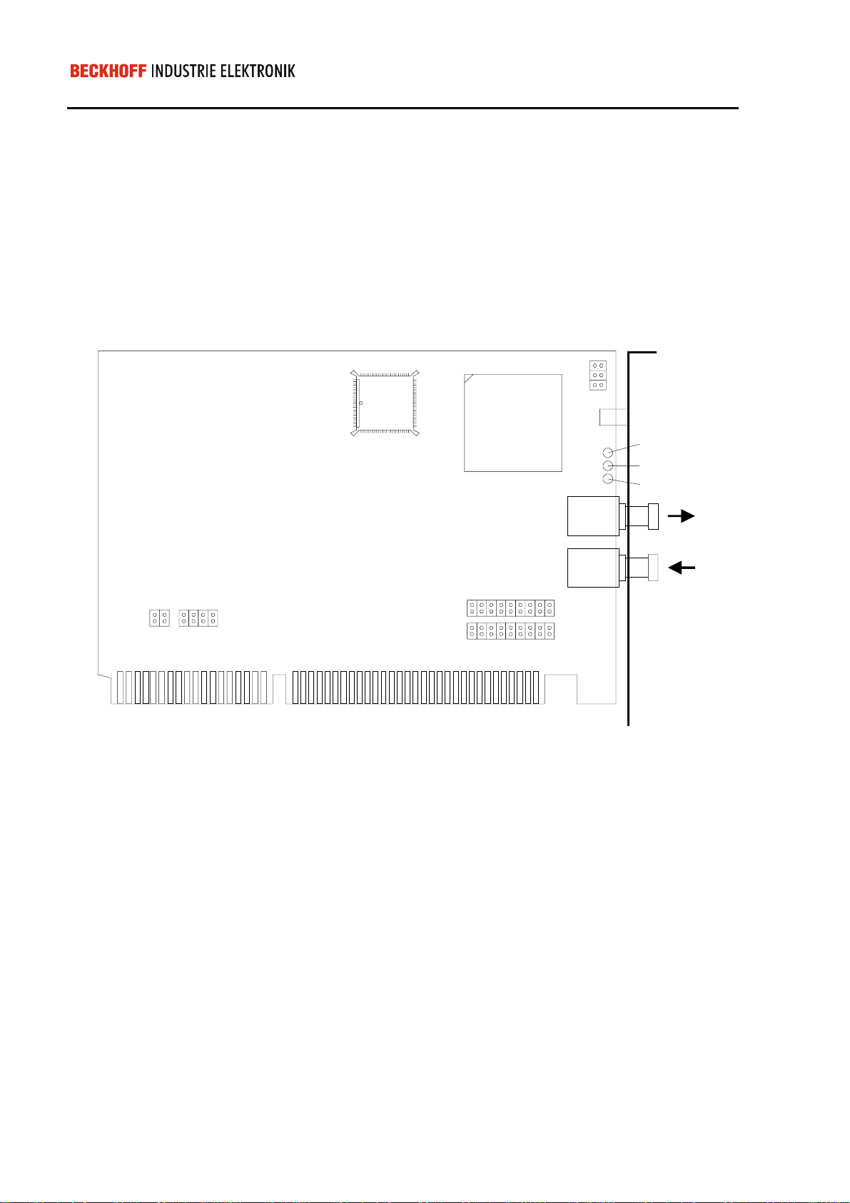
Jumper configuration
The C1220 interface card occupies one ISA bus slot on the PC’s bus
board. The fibre-optic r ing is connected wit h two fibre optic connec ters on
the panel.
Jumpers J1 and J2
Jumpers J3 and J4
The base address f or the req uir ed 4 kbyte area of the PC address spac e is
set by means of jumpers J2 and J1:
&
'
- -
'
(
The IRQ number of the Read y interrupt is defin ed by means of jumper J3.
Jumper J4 defines the IRQ number of the fast interrupt inputs.
,54
,54
Beckhoff Lightbus - PC interface card C1220
-
-
,54
,54
,54
,54
,54
,54
,54
Page 30

Eiserstraße 5 / D-33415 Verl / Telefon 05246/963-0 / Telefax 05246/963-149
/('581
/('&38(UURU
/('/LJKWEXV(UURU
Installation notes 30
Status display
There are 3 status display LEDs on the C1220.
“RUN“ LED
“CPU-Error“ LED
“Lightbus-Error“ LED
The ’RUN’ LED indicates that the C1220 has initialized without errors and
is ready for operation.
An irrecoverable h ardware fault has occurred if only this LED lights up. If
the ‘RUN’ LED also lights up, a program error has occurred which it m ight
be possible to remedy by means of a hardware reset.
’LWL-FAIL’ LED is activated if a def ect occurs in the fibre optic ring during
operation. The LED flashes if a gener al fibre-optic er ror has occurr ed. The
LED is statically activated if the error has occurred during the resident
address check. Updating of the proces s im age is interr upted. The c ause of
the error can be determined by means of the available diagnostic functions.
Installation in the PC
1. Switch off the PC and any external power supplies.
2. Insert the C1220 interface card in a 16-Bit ISA bus slot on the PC’s
bus board.
The C1220 does not require an external power supply. The card is
powered directly by the PC. Therefore, when the PC is switched on, the
C1220 also assum es operation. Before the C122 0 can assume operat ion,
however, the fibre- optic connections m ust be establishe d and the j umpers
of the C1220 must be configured correctly.
Beckhoff Lightbus - PC interface card C1220
 Loading...