

Page 1

C1120 S5 to II/O Lightbus Interface Beckhoff II/O-Lightbus System
C1120
S5 to II/O-Lightbus Interface
Technical Documentation
VERSION 2.1
Date 27.06.97 Version 2.1 Page 1 of 52
Page 2

C1120 S5 to II/O-Lightbus Interface Beckhoff II/O-Lightbus System
Table of contents
1 FUNCTIONAL DESCRIPTION OF HARDWARE..................................................................................... 3
2 FUNCTIONAL DESCRIPTION OF SOFTWARE...................................................................................... 4
2.1 Installation of Software ..................................................................................................................................... 4
2.2 Main menu......................................................................................................................................................... 5
2.3 Master Setup...................................................................................................................................................... 7
C1120 Configuration......................................................................................................................................... 9
C1120 I/O Memory Map List.......................................................................................................................... 13
Timer and Interrupts........................................................................................................................................ 19
C1100 to C1120 Project Conversion............................................................................................................... 21
Online Menu....................................................................................................................................................22
Debug Menu.................................................................................................................................................... 24
How to get started - setting up an I/O list........................................................................................................ 25
Status register S5 / C1120................................................................................................................................26
Parallel Communication Channel .................................................................................................................... 27
Table of error numbers:................................................................................................................................... 31
Service Routines in STEP 5 language.............................................................................................................. 32
Status LEDs..................................................................................................................................................... 33
2.4 Slave Setup......................................................................................................................................................34
Edit Inputs ....................................................................................................................................................... 36
Edit Outputs..................................................................................................................................................... 37
Edit Configuration........................................................................................................................................... 38
Online Menu....................................................................................................................................................40
2.5 Project Manager .............................................................................................................................................. 42
2.6 System Configuration...................................................................................................................................... 44
System Entry....................................................................................................................................................44
System ............................................................................................................................................................. 45
Language ......................................................................................................................................................... 46
Log File ........................................................................................................................................................... 47
Program Parameter.......................................................................................................................................... 48
3 C1120 INTERFACE: TECHNICAL DATA................................................................................................49
4 INSTALLATION REMARKS......................................................................................................................50
4.1 Assembly to the S5-PLC rack.......................................................................................................................... 50
4.2 Connecting to a PC.......................................................................................................................................... 50
System requirements........................................................................................................................................50
Interface ports for connection with a PC ......................................................................................................... 51
5 C1120 SERIAL PORT PINOUT.................................................................................................................. 52
Page 2 of 52 Version 2.1 Date 27.06.97
Page 3
C1120 S5 to II/O Lightbus Interface Beckhoff II/O-Lightbus System
1 Functional description of Hardware
C1120
General
The interface card C1120 is an intelligent interface between the BECKHOFF II/O-Lightbus
System and a SIEMENS SIMATIC S5 PLC. The SIEMENS PLC program is enabled to
access binary and analog inputs and outputs of the II/O-Lightbus System via a Dual Ported
RAM of the interface card. The I/O addresses of the II/O-Lightbus System are mapped to the
S5 I/O address memory map with a configuration program running on a personal computer.
The interface card C1120 is placed in a PLC slot for ‘intelligent peripherial devices’.
Date 27.06.97 Version 2.1 Page 3 of 52
Page 4

C1120 S5 to II/O-Lightbus Interface Beckhoff II/O-Lightbus System
2 Functional description of Software
For further documentation it is assumed that the interface card C1120 is connected to a PC
running DOS with a serial interface cable to COMx.
2.1 Installation of Software
First step: Backup copy of installation disc
Do not forget to backup your installation disc and use the backup copy instead of the original
software disc.
- switch on your PC
- Use DISCCOPY to backup your installation disc
- Use your backup disc for the installation.
Installation to hard disc
1. switch on your PC
2. (generate and) change to your destination directory
3. insert the installation disc copy to floppy drive A:.
4. change to drive A:;
4. type: ’INSTALL C: <RETURN>’
The installation routine will copy all files to your destination directory of disc C: (or equiv.).
Start of program
start the C1120 setup program with ’PROGRAM <RETURN>’ from your
destination directory of your PC.
Page 4 of 52 Version 2.1 Date 27.06.97
Page 5
C1120 S5 to II/O Lightbus Interface Beckhoff II/O-Lightbus System
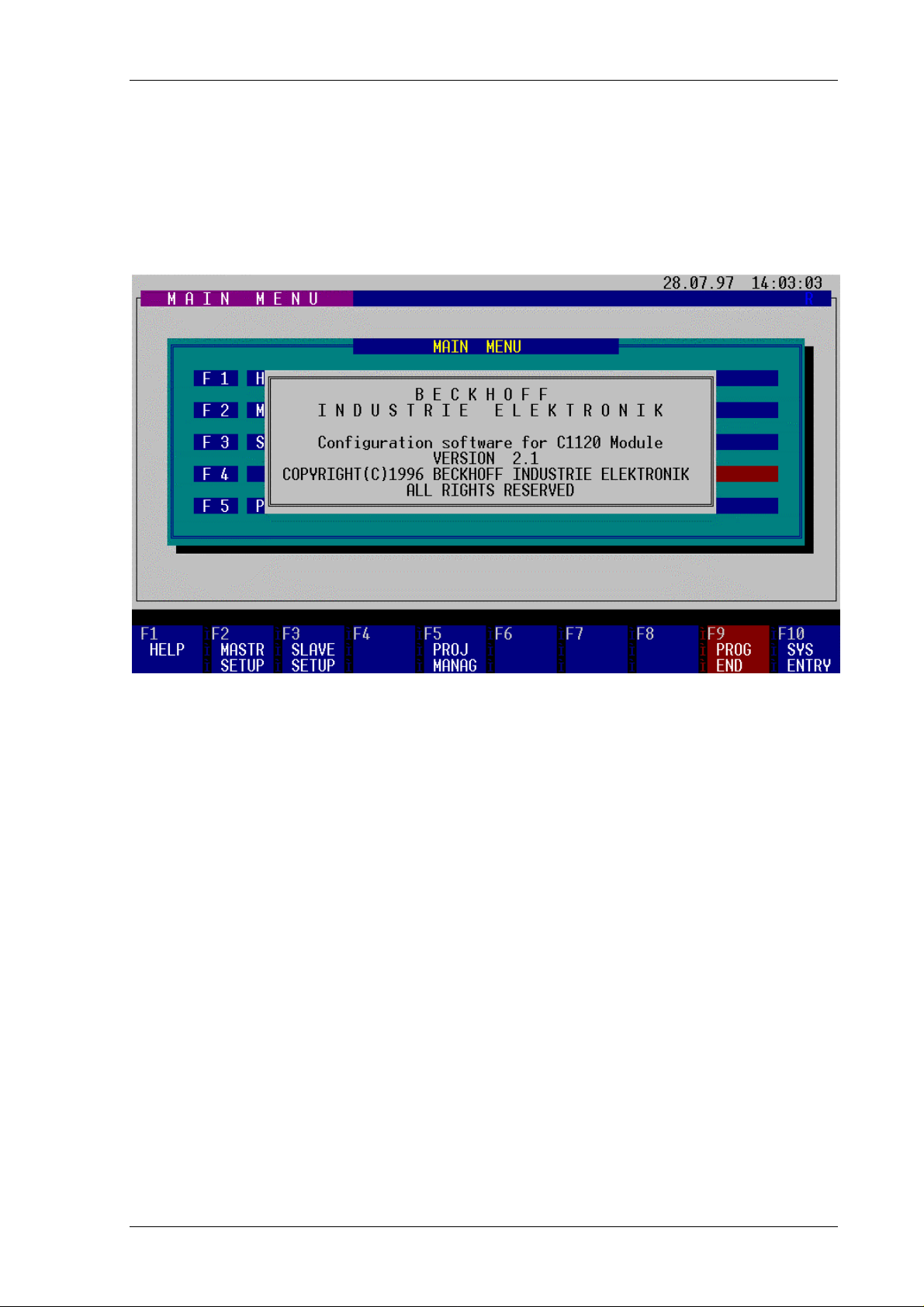
2.2 Main menu
First screen after the start of program shows:
All actions are taken with the function keys F1 to F10. Some actions are provided with
security questions. If the desired action is valid, type ‘J’ or ‘Y’ to activate, ‘N’ or ESC to quit.
By choosing the key ESC you are able to return to the higher menu levels.
Function keys
F1 HELP
Shows a help text for the equivalent menu and function keys.
F2 MASTER SETUP
changes to the master setup menu to map the II/O Lightbus System addresses to
the I/O addresses of the SIEMENS PLC.
F3 SLAVE SETUP
changes to slave setup
F5 PROJECT MANAGER
changes to the project manager menu to choose the working project from a list of
(setup) projects.
Date 27.06.97 Version 2.1 Page 5 of 52
Page 6

C1120 S5 to II/O-Lightbus Interface Beckhoff II/O-Lightbus System
F9 PROGRAM END
returns to DOS after closing the application.
F10 SYSTEM ENTRY
changes to the setup menu of the running program.
Page 6 of 52 Version 2.1 Date 27.06.97
Page 7
C1120 S5 to II/O Lightbus Interface Beckhoff II/O-Lightbus System
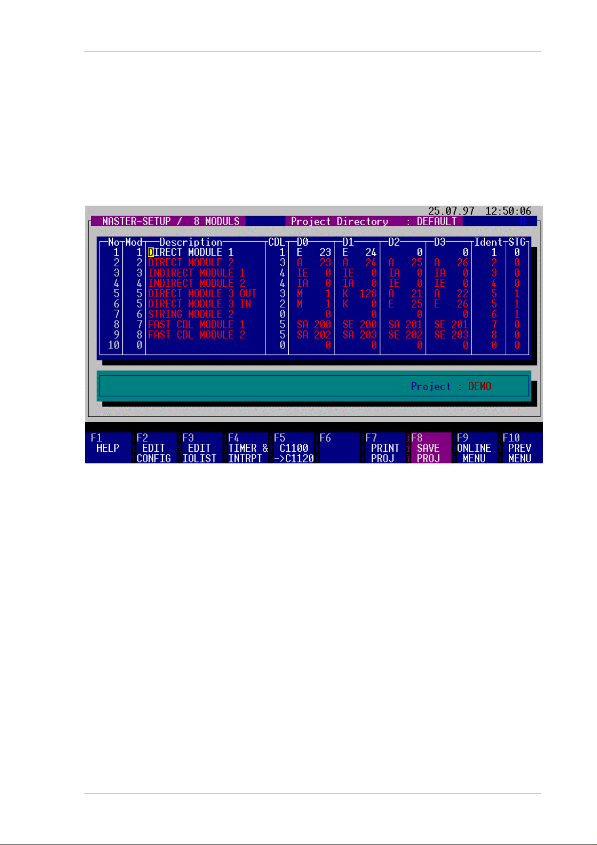
2.3 Master Setup
The master setup menu is accessed by pressing F2 key from the main menu. With this menu,
the address mapping between the II/O-Lightbus system and the SIEMENS PLC is displayed
and can be edited, saved under a project name and transfered from and to the C1120 card.
The screen shows different fields for input, status line and function key setup.
Function keys:
F1 HELP
Shows a help text for the equivalent menu and function keys.
F2 EDIT CONFIGURATION
with this menu you can change the C1120 configuration.
F3 EDIT I/O LIST
with this menu you can modify the I/O address map list.
F4 TIMER & INTERRUPTS
with this menu you can configure the four fast fieldbus interrupts of the Beckhoff
II/O Lightbus System.
Date 27.06.97 Version 2.1 Page 7 of 52
Page 8

C1120 S5 to II/O-Lightbus Interface Beckhoff II/O-Lightbus System
F5 C1100 -> C1120
with this menu projects of the Beckhoff C1100 card are converted to C1120
projects.
F7 PRINT I/O LIST
prints the I/O map to your printer on LPT1:.
F8 SAVE PROJECT
stores the setup of C1120 under a project name - if first time used you are asked
for a project name. At further store commands, a <RETURN> stores under
existing project name.
F9 ONLINE MENU
changes to the communication menu to exchange data with the C1120 card.
F10 PREVIOUS MENU
returns to the previous menu.
Page 8 of 52 Version 2.1 Date 27.06.97
Page 9
C1120 S5 to II/O Lightbus Interface Beckhoff II/O-Lightbus System
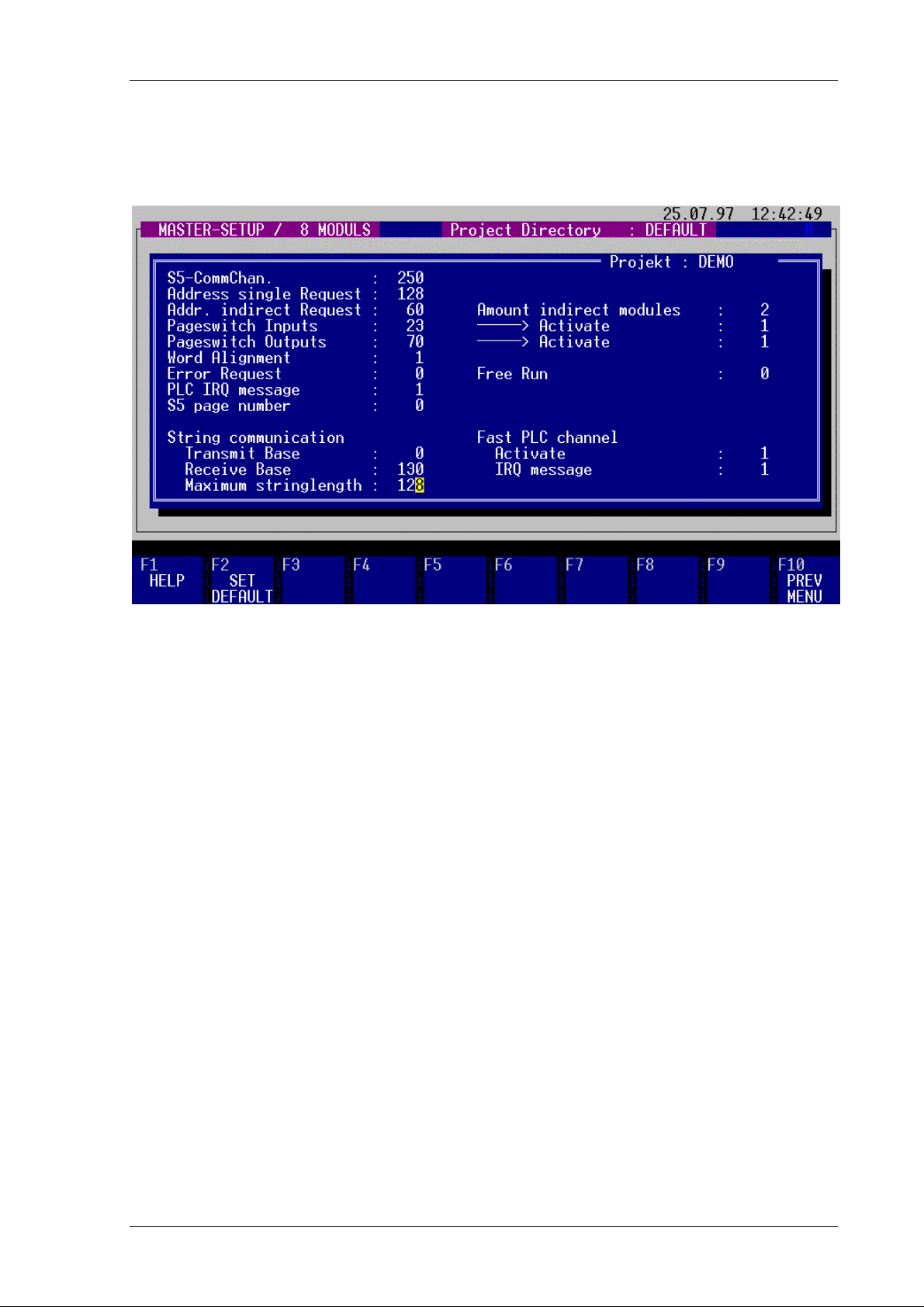
C1120 Configuration
with this menu you can change the C1120 configuration to setup all necessary parameters for
the C1120 interface.
The field "S5-CommChannnel" describes the base address for the parallel channel functions
(see chapter "parallel channel" ). For use of more than one C1120 cards in one PLC the base
address default of 250 for the communication channel can be changed to an other address (
from address 128 - 250, length 6 Byte ). The address for status register will automatically
change to input value +4 and the address for interrupt request will change to input value +5.
A single request is able to access an II/O Lightbus module directly without synchronized
exchange with the process image (between read of input process image and output process
image write)*, by use of the STEP 5 commands "Load I/O process peripherials" e.g. "
Transfer I/O process peripherials ". Therefore, the base address "Address single request" of
an address block for the single request is to be defined between 128 and 250. By setting a "0"
for the base address "Address single request" the single request is disabled.
________________
* the PLC updates the Transfer Pr oc ess Image automatically
Date 27.06.97 Version 2.1 Page 9 of 52
Page 10

C1120 S5 to II/O-Lightbus Interface Beckhoff II/O-Lightbus System
To enlarge the I/O address space, the use of "indirect modules" is available - a list of module
data fields is stored in the C1120 RAM memory. The base address to exchange data with the
Process image of the PLC is defined here (see equiv. chapter).
To obtain correct data for the PLC process image, the process image memory of the C1120 is
divided in pages, which each by each are switched towards the PLC and towards the II/O
Lightbus to refresh data contents. The pageswitch mechanism changes the memory pages to
and from the PLC. The pageswitch inputs are defined as lowest address, the pageswitch
outputs are defined as highest address by default.
By writing a "1" to the field "word alignment", the PLC is enabled to access the process
image by word commands (16 bit - wise) The necessary selects are generated automatically.
For use of more than one C1120, the word alignement can be disabled by overwriting a "0".
The default setup value of "0" in the field "Error request" enables the C1120 to stop the PLC
with a timeout status of the C1120 in case errors occur on the II/O-Lightbus System, the
C1120 interface deletes the I/O addresses in the Dual Ported RAM mapped to the PLC in case
of error. By programming OB 23 and OB 28 the timeout can be managed by PLC software.
By setting the field value "Error request" to "1", the I/O addresses are not deleted in case of
errors. The latest input data values are held in place, the writing of outputs data is confirmed,
but writing is not executed, the error flag in the status byte is set.
IMPORTANT REMARK:
By use of option "1" the user has to achieve the check of the status byte error
flag in every PLC cycle to branch into a error routine, if the error flag is set.
After occurance of the error flag the fault number and number of modules can
be read via the parallel communication channel. After return from the fault
situation (repair of fiber optic media) a start of the II/O-Lightbus System can be
forced by resetting the C1120 by software from the PLC.
In case of no success of the reset function, the error flag is set again, and as a
return value of the function RESET-LWL the value of the init- error is returned
(refer to chapter "Parellel communication channel").
Page 10 of 52 Version 2.1 Date 27.06.97
Page 11

C1120 S5 to II/O Lightbus Interface Beckhoff II/O-Lightbus System
By setting the "Free Run" option to "1" in the equivalent mask, the inputs of the II/O-Lightbus
System are read asyncronously to the PLC- process image at maximum II/O Lightbus
communication refresh rate. The pageswitch mechanism displayes the newest process image
memory page to the PLC.
Entering a “1” in the field PLC IRQ Frame causes the C1120 to send an extra control and
interrupt message frame for triggering a local process image cycle on the intelligent peripheral
modules. Those message frames are appended to the process data message frames.
The current page address of the C1120 is entered in the Page Number field.
String communication is used for communicating with intelligent peripheral modules. It can
be used, among other things, for configuring the modules. The data packages (strings) are
transmitted to the C1120 by way of the page frame.
The field Transmit Basis is for entering the page frame offset for the strings being sent. It
should be noted that starting from the offset, 2 bytes are reserved for the handshake between
PLC and C11220. The actual string is entered starting at the offset + 2.
The field Receive Basis is for entering the page frame offset for the st rings being received. It
should be noted that starting from the offset, 2 bytes are reserved for the handshake between
PLC and C11220. The actual string is entered starting at the offset + 2.
The field Maximum String Length is for entering the maximum permissible length of the
strings.
The purpose of the fast communications channel is for improved process synchronisation
during multi-processor operation (see also “Fast Communications Channel”).
Entering a “1” in the Activate field enables the fast communications channel (see also “Fast
Communications Channel”).
Entering a “1” in the field IRQ Frame causes the C1120 to send an extra control and
interrupt message frame for triggering a local process image cycle on the intelligent peripheral
modules assigned to the process channel. Those message frames are appended to the process
data message frames.
Date 27.06.97 Version 2.1 Page 11 of 52
Page 12

C1120 S5 to II/O-Lightbus Interface Beckhoff II/O-Lightbus System
function keys
F1 HELP
displays help text.
F2 SET DEFAULT
sets configuration parameters to default.
F10 PREVIOUS MENU
returns to the master setup menu.
IMPORTANT REMARK regarding the page number:
The page number for data exchange with the PLC is configurable, beginning with
interface version numbers above V 1.51. Up to Version 1.51, the page number for
data exchange is 0 by default.
Page 12 of 52 Version 2.1 Date 27.06.97
Page 13
C1120 S5 to II/O Lightbus Interface Beckhoff II/O-Lightbus System
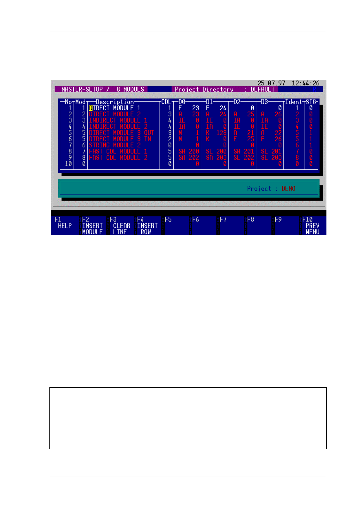
C1120 I/O Memory Map List
All used II/O-Lightbus modules must be listed in the I/O list. The order of modules in the I/O
list must reflect their physical position in the II/O-Lightbus System ring.
First step is to edit the I/O list:
Each new module is to be introduced to the list by pressing "F2": "Insert module". No actions
take place during editing without adding a module as described. Addresses of existing
modules can be edited and overwritten easily, modules can be deleted by pressing "F3". If a
module is deleted, it has to be removed from the II/O-Lightbus System ring.
The coloumn "No" holds the actual line number. The coloumn "Mod" holds the corresponding
module address. The coloumn "Msg" is without further use. The coloumn "Description" keeps
a 20 character user description of the module name or function. The "CDL" - coloumn is used
internally.
The address name of the SIEMENS PLC process image is entered in the fields "D0" to "D3".
You can use any order or use addresses twice etc.
The coloumn "Ident" maps the indirect modules to their physical II/O-Lightbus address.
In the column “STG”, those modules that are to be processed as part of the string
communication are identified by a “1”. Those modules are similarly assigned to their
physical module addresses by means of the Ident number.
Warning ! The interface card C1120 is not able to identify modules. If the I/O list and
physical order of modules are different, or the inputs and outputs are set up
incorrectly by DIP switches, I/O data is transferred erroneous from the PLC
program to the modules without recognition.
Date 27.06.97 Version 2.1 Page 13 of 52
Page 14

C1120 S5 to II/O-Lightbus Interface Beckhoff II/O-Lightbus System
Function keys
F1 HELP
displays help text.
F2 INSERT MODULE
by pressing "F2" a new module is inserted at the current cursor position. The
address is set to the equivalent line number. Following module addresses are
incremented. After inserting a new module, description, I/O addresses and ident
no. can be edited. Every line of the I/O list, containing a module number and I/O
addresses, generates one telegram for II/O-Lightbus per PLC cycle.
F3 CLEAR MODULE
by pressing "F3" a line of the II/O setup is deleted. A confirmation is necessary
for that action to take place.
Warning ! In case of deleting a module from the I/O list, it is definitively
necessary to remove the equivalent module from the II/OLightbus ring. Otherwise the II/O-Lightbus ring is incorrectly
configured and is not ready to work.
F4 INSERT ROW
If it is necessary to serve a module with more than one telegram per cycle,
additional telegrams are generated by inserting a line to an existing module entry.
In this case, the inserted line holds the same module number as the line before.
F10 PREVIOUS MENU
returns to the master setup menu.
Page 14 of 52 Version 2.1 Date 27.06.97
Page 15

C1120 S5 to II/O Lightbus Interface Beckhoff II/O-Lightbus System
Modules can be set up in the configuration list as:
- direct module or
- indirect module,
depending on the necessity of access in every PLC cycle. This is supplied to enlarge the
address space of the PLC above 128 bytes process image.
Direct modules
Direct modules are mapped directly to the PLC process image. The PLC process image
addresses are edited in the I/O byte addresses D0 to D3 of every telegram frame belonging to
the module - each line in the setup screen belongs to a dedicated II/O-Lightbus telegram frame
to the addressed module. The address names (e.g. O 10) of the PLC programm are used for
reference.
Example given: the modules 1 and 2 are mapped as direct modules. The STEP5 program
accesses the I/O addresses 23 to 26, the C1120 maps the I/O data to the modules 1 and 2:
IB 23, IB 24 from module 1
OB 23, OB 24, OB 25, OB 26 to module 2
The inputs and outputs can be addressed bit-, byte-, or wordwise:
I 23.0 ... I 23.7, oder IW 23 = IB 23 & IB 24
are handled as usual.
All direct mapped modules are refreshed synchronously and cyclic with the PLC cycle and
process image refresh. The direct mapped modules can be accessed directly from the PLC
program at any time.
The modules 7 and 8 are also direct modules. However, they are assigned to the fast
communications channel by means of their identification codes “SA” and “SE” respectively.
If intelligent modules are to be addressed during the PLC cycle (e.g. terminal bus coupler) the
first two data bytes (D0, D1) can be assigned constants. Those constants are entered with the
identification codes “M” (for memory) and “C” (for constant).
In the example, D0 on module 5 is assigned the fixed value 1 (“M”) and D1 the fixed value
128 (“C”).
Date 27.06.97 Version 2.1 Page 15 of 52
Page 16

C1120 S5 to II/O-Lightbus Interface Beckhoff II/O-Lightbus System
Indirect modules
To enlarge the address space of the PLC system, modules can be mapped "indirectly":
they are accessed via a list of "indirect" communications, being addressed by a dedicat ed base
address. These communications are processed in every PLC cycle. They can be used to
enlarge the address space of 128 I/O Bytes of the PLC by placing the base address of the
indirect communication list above 128. Another option is to change the contents of the I/O list
cycle by cycle: a part of the II/O-Lightbus modules are mapped in a round robin way to the
indirect I/O list to fit the to tal number of II/O Lightbus I/O bytes to the I/O address space of
the PLC, with the effect, that those modules are being served only at occurence in the indirect
communications list. One or more modules can be mapped to the indirect communications
list. A single address block consists of the module address (IDENT number) and four bytes of
I/O data. The reservation of memory space is done with the menu "Edit configuration": After
definition of the base address of the indirect I/O list it is necessary to allocate 5 x (number of
modules) Bytes list size: First byte contains the address number, following four bytes
containing the I/O data. The list ends with a "0" found in an address byte location. These
addresses are not available for standard I/O via PLC process image transfer. Address conflicts
have to be avoided by the PLC programmer.
Arbitration of indirect modules
Indirect modules are listed in the I/O setup list, coloumn "D0 .. D3" with IE or IA, with
address number 0. The choice of IE or IA is without use for the communication and only
indicates the configuration of the II/O-Lightbus modules for input (IE) or output (EA).
By use of the indirect communications list every module in the II/O Lightbus System can be
accessed, even the direct configured: Their IDENT- number has to be placed in the first
address block address location, following four bytes keep I/O data. By this, the module is
accessed via the indirect communication mechanism. By replacing the IDENT number in the
first location of the address block with "0", the indirect communication is skipped. If the
programmer decides to address a direct module via indirect communication, the module is
addressed twice by the II/O-Lightbus System.
Important! If inputs are read via indirect communication, the programmer has to regard
that input informations are valid one cycle after the following. Outputs are
written during the following cycle . This effect can be managed by using the
statusbyte of the PLC (PB/PY 254): Bit 1 acts as life bit and changes status
every cycle. By reading the life bit the programmer can recognize and count
cycles (refer also to chapter "status register S5/C1120).
Example:
In above shown setup screen the modules 3 and 4 are mapped indirect. The base address for
indirect communications list is set up to 60, number of indirect modules is 2. By this, 10
Bytes of address block space are available for the programmer: By te 60 contains the IDENTnumber of module 3 (3), the bytes 61 to 64 are I/O data for module 3. Address 65 keeps the
IDENT number of module 4 (4), bytes 66 to 69 are I/O data for module 4. Byte 70 is available
for standard or direct I/O.
Page 16 of 52 Version 2.1 Date 27.06.97
Page 17

C1120 S5 to II/O Lightbus Interface Beckhoff II/O-Lightbus System
Arbitration of a single load /transfer of peripherial bytes
As used with the indirect communications list every module in the II/O Lightbus System can
be accessed immediately via a single communication list: The IDENT- number of a dedicated
module has to be placed in the first address block address location, following four bytes keep
the I/O data.
For handshake purposes two bits in the Status Byte of the PLC can be used: PB/PY254 and
PB/PY 255 Bit 0:
First, IDENT number and I/O data are written to the single communication list. Then, bit 0 of
PB/PY 254 is set (strobe bit) by the PLC. After this, a transfer to PB PY 255 with any data
forces an interrupt and II/O Lightbus communication with the C1120 interface.
The C1120 interface card responds with setting the bit 0 of PB/PY 254 (ACK bit): the data
byte contents are valid and can be read by the PLC with L PB. The PLC handshakes with
resetting the bit 0 of PB/PY 254 (strobe bit). The C1120 ends the handshake cycle by resetting
the ACK bit 0 of PB/PY 254.
By setting "address single communication" to 0 in the setup screen, this option is not
supported during the use with this setup.
Example :
The value of the single communication address is set to 128.
S5 C1120
1.) Transfer identnumber for dedicated
II/O-Lightbus module address to
PB/PY 128
2.) Transfer transmit data from memory
flags or equiv. to PB/PY 129,130, 131,
132
3.) Set strobebit
LKB 1
T PB/PY 254
4.) Force interrupt on C1120: transfer
something to PB/PY255
L KH AFFE
T PY 255
5.) Polling of ack- bit in statusregister II/O-Lightbus communication doing
transfer to and from the module
6.) Set of Ack.- bit in statusregister
7.) Load of valid data from the single
communication list to destination
LPW
TDW
TMW
8.) Reset strobebit
Polling of ack- bit in statusregister
9.) Reset of Ack.- bit in statusregister
Date 27.06.97 Version 2.1 Page 17 of 52
Page 18

C1120 S5 to II/O-Lightbus Interface Beckhoff II/O-Lightbus System
Fast Communications Channel
If the S5 is run in multi-processor mode, one CPU can be assigned the fast communications
channel in order to improve process image synchronisation.
The fast communications channel works only with a selection of peripheral modules which
are given the identification codes “SA” or “SE” on the IO List. The range of values for the
entries is from 128 to 255. The priority for fast communication is lower than for single box
mode and higher than for cyclical operation.
To activate the channel, you must enter the option “ 1” in the Activate field in the menu
option Edit Configuration.
Handling of Fast Communications Channel
The fast communications channel is operated with a handshake procedure.
The sequence for the individual steps is described below.
S5 C1120
1.) Writes a 1 to the cell
Page + 1023 (Interrupt)
2.) Polls the cell Page + 1022 while cell
equals 0
3.)
-”-
4.) Writes a 0 to the cell
Page + 1023 (Interrupt)
5.) Polls the cell Page + 1022 while cell
equals 1
Process image for fast
communications channel is updated
Process image is updated,
Acknowledged by writing a 1 to the
cell Page + 1022
Writes a 0 to the cell
Page + 1022
Page 18 of 52 Version 2.1 Date 27.06.97
Page 19

C1120 S5 to II/O Lightbus Interface Beckhoff II/O-Lightbus System
Timer and Interrupts
With this menu the four fast interrupts of the Beckhoff II/O-Lightbus System can be
configured:
It is possible to connect the interrupts with a free running timer. To select the timer period,
enter the timer period in the equivalent field. Valid values are 0 ms (meaning "timer
disabled") up to 1677 ms.
Interrupts can be counted: The field "count address" holds the base address of the counters of
the four interrupts. Each counter is two bytes long, therefore 8 bytes are reserved. To enable a
counter, the field "Count" should hold a "1".
The fast interrupts are configured by moving the cursor the the equivalent line and interrupt
field, pressing key "F6" repetitively to choose the characteristic from "not activated", "rising
edge", "negative edge", "toggle".
The fast interrupts are configured by positioning the cursor on the relevant interrupt field and
pressing the function key F6 to select the desired characteristic. Pressing the F6 key toggles
between the options “ Not Activated” , “ Positive Edge” , “ Negative Edge” and “ Change of
Edge” .
If the relevant interrupt channel is activated by a “ 1” in the column “ S5 IRQ” , when the
interrupt event occurs, an interrupt is triggered on the S5.
An interrupt request is reset by reading a specific cell in the Dual Port RAM. The base address
entered in the field S5 IRQ Address indicates the address offset. In the example, accessing
the address 190 would reset interrupt request 0, and accessing address 192 would reset
interrupt request 2.
Date 27.06.97 Version 2.1 Page 19 of 52
Page 20

C1120 S5 to II/O-Lightbus Interface Beckhoff II/O-Lightbus System
It is possible to count the number of interrupt events occurring within a specific time interval.
The time interval can be entered in the field “Timer Period” and must be in the range 0 ms
(timer disabled) to 1677 ms.
The relevant interrupt channel must be activated by entering a “1” in the field “Count”.
The start address from which the count results are to be stored is entered in the field “Count
Address”.
The count results are in the form of a 16-bit value so that 2 bytes are reserved for each
counter. In the example, the count result from interrupt channel 1 would be stored starting at
address 182, and the count result from interrupt channel 2 starting from address 184.
Function keys:
F1 HELP
displays help text.
F6 IRQ CONFIGURATION
chooses the interrupt characteristic (see above).
F10 PREVIOUS MENU
returns to master setup menu.
Page 20 of 52 Version 2.1 Date 27.06.97
Page 21

C1120 S5 to II/O Lightbus Interface Beckhoff II/O-Lightbus System
C1100 to C1120 Project Conversion
This menu helps to convert setups saved under a specific project name for the C1100 interface
to a C1120 interface project:
To start conversion, the path, directory name and project name have to be entered in the
equivalent lines (e.g. " C:\C1100\SYS\").
The projectname of the C1120 project to be generated is entered in the field C1120 project
name. Path and directory of the C1120 project can be changed in the menu "Project Manager"
To start conversion, press "F2".
Parameters of the C1100 which are no longer needed are discarded, others set to default
values (see menu "Edit Coniguration").
Function keys:
F1 HELP
displays help text.
F2 CONVERT
The conversion is started with this menu.
F10 PREVIOUS MENU
returns to master setup menu.
Date 27.06.97 Version 2.1 Page 21 of 52
Page 22

C1120 S5 to II/O-Lightbus Interface Beckhoff II/O-Lightbus System
Online Menu
For transfer of setups from a PC to the C1120 interface and back, the online menu helps to
control communication actions, saving and printing of project setups:
If a communication timeout occurs during or at start of a transfer, first action to be taken
should be to check the RS232 interface cable and the serial interface parameters in the menu
"Program Parameters".
Function keys:
F1 HELP
displays help text.
F2 RESET C1120
Generates a software reset of the C1120 interface. The interface boots and runs
through following steps:
- self test of the C1120 interface,
- the configuration saved in the EEPROM memory is loaded and activated,
- the II/O-Lightbus ring is reset.
The status of the C1120 is displayed after completion of the reset in the status
line. This function can be activated only while the PLC is in STOP mode.
Page 22 of 52 Version 2.1 Date 27.06.97
Page 23

C1120 S5 to II/O Lightbus Interface Beckhoff II/O-Lightbus System
F3 FRACT TEST
This menu command tests the II/O-Lightbus ring and reports the number of
integrated modules or - in case of errors - the location of a ring interruption.
F4 TRANSMIT CONTROL
With this test it is possible to take the II/O-Lightbus ring under observation, e.g. to
find a ring fault: After start of this test, all modules from the C1120 interface to
the ring interruption show the "CYCLE" LED. After the ring interruption, the
"CYCLE" LED of modules is off, possibly showing the red "ERROR" LED.
Switching back to standard mode is done with a RESET.
During the TRANSMIT CONTROL, the PLC must reside in STOP mode.
F5 PC -> C1120
Transmits the contents of the I/O list to the C1120 interface. The interface will
work properly only after completion of this download, followed by a RESET or
cold boot. During download, the PLC must reside in STOP mode.
F6 C1120 -> PC
Reads the actual I/O configuration from a C1120 interface.
F9 DEBUG MENU
Changes to the debug menu. Occuring II/O-Lightbus errors are reported here.
F10 PREVIOUS MENU
returns to master setup menu.
Date 27.06.97 Version 2.1 Page 23 of 52
Page 24

C1120 S5 to II/O-Lightbus Interface Beckhoff II/O-Lightbus System
Debug Menu
The debug menu helps to analyze the status and quality of the II/O-Lightbus ring. Two tables
show the parity error and status information:
The parity error table allows to analyze and identify the location of parity error sources. To
use this option, II/O-Lightbus modules must be configured with SPROMS of type "132".
The II/O error status table shows an overview of all occured I/O errors.
Function keys:
F1 HELP
displays help text.
F6 IIO ERRORS
The display is refreshed to actual status by pressing "F6".
F10 PREVIOUS MENU
returns to master setup menu.
Page 24 of 52 Version 2.1 Date 27.06.97
Page 25

C1120 S5 to II/O Lightbus Interface Beckhoff II/O-Lightbus System
How to get started - setting up an I/O list
- Connect PC with the C1120 interface with the interface cable.
- Power on PLC and PC: PLC must reside in STOP mode, II/O-Lightbus ring has to
be closed before Power on.
- Start PC program for C1120 configuration.
- Check the setup of the serial port with the help of the setup menu.
- Change to the master setup menu.
- Edit the I/O-list: Enter the modules in the order of occurence in the II/O-Lightbus
ring. Enter the PLC-I/O-addresses.
- Save the configuration in a file with the name of the field "filename". ( At first
installation and at start of the program, this file is named DEFAULT.IOL).
- Change to the online menu.
- Force a download to transfer the I/O-list to the C1120-interface.
- Reset the C1120 interface to start with the new configuration.
- set S5-PLC to run mode: force the S5 -PLC to read the I/O configuration at start.
The C1120- configuration is recognized by the PLC.
Date 27.06.97 Version 2.1 Page 25 of 52
Page 26

C1120 S5 to II/O-Lightbus Interface Beckhoff II/O-Lightbus System
Status register S5 / C1120
The C1120 interface occupies the addresses PB/PY 250 to PB/PY 255 by default. This setup
is configurable. By generating a single transfer to peripherial byte PB/PY 255 (T PB 255) the
C1120 interface is interrupted for a single request. The peripherial byte PB/PY 254 is the
status register C1120.
S5 input status (readable with the command L PB 254)
Bit 0 : ACKN : acknowlege "single request II/O-Lightbus cycle finished"
Bit 1 : LIFE : This status bit toggles before transmission of I/O data to and from the
modules on the I/O list. By monitoring the LIFE bit in the STEP 5 program
it is possible to supervise the transmission of information to the indirect
modules, especially in case of short PLC cycle times.
Bit 2 : LWL-ERROR : This bit is set, if an error occurs in the II/O-Lightbus
System. Depending on the configuration of the field "error request" the PLC
reacts with a change to STOP mode ("error request" = "0") or not ("error
request" = "1").
Bit 3 : Local error on BK2000 module
Bit 4 : INPUT-VALID : indicates the input data to be valid after reset or program
start. The bit is set after complete initialization of the II/O-Lightbus System
and stays to be logic "1" afterwards.
S5 Output status (writeable with the command T PB 254)
Bit 0: Strobe bit for a single request.
Bit 1: Cycle mode ON ("0") or OFF ("1").
By setting this bit to "1", the cycle mode transmissions are stopped. Inputs
and Outputs are accessible only by single requests, until the cycle mode is
enabled again.
Bit 2: Free running mode (bit processing only)
The free running mode disables the cycle mode. Information is transmitted
in an asynchronous way on the II/O Lightbus ring. Data bytes, which belong
together, have to be transmitted via the single request. The life bit is passive
in this mode.
Page 26 of 52 Version 2.1 Date 27.06.97
Page 27

C1120 S5 to II/O Lightbus Interface Beckhoff II/O-Lightbus System
Parallel Communication Channel
The parallel channel is used to start service functions of the C1120 interface. The channel
occupies the addresses 250 to 253 by default. This setup can be changed to any address
between 128 and 255.
The following information structure is available (shown for PB/PY default):
PB/PY 253 = parallel channel handshake
PB/PY 252 = parallel channel function number
PB/PY 251 = parallel channel argument 1
PB/PY 250 = parallel channel argument 2
The handshake is carried out with the peripherial address PB/PY 253 or equivalent. Following
control bits represent status information to both sides ( S5 --> C1120 and C1120 --> S5 ):
Bit 253.7: strobebit for parallel handshake
Bit 253.6: acknowlege bit for parallel handshake
The PLC is always the master of the communication via the parallel channel: the function call
is handed to the C1120 interface. The C1120 responds with data belonging to the function
call.
Date 27.06.97 Version 2.1 Page 27 of 52
Page 28

C1120 S5 to II/O-Lightbus Interface Beckhoff II/O-Lightbus System
How to program a parallel channel communication:
a.) Request of the Siemens PLC to the C1120 interface (master is transmitter)
1. Write function number to PB/PY 252
2. Write argument 1 to PB/PY 251
3. Write argument 2 to PB/PY 250
4. Set strobe bit PB/PY 253.7
5. Wait for C1120 acknowlege bit PB/PY 253.6 to be "1" (function is started by
C1120 interface)
6. Reset strobe bit PB/PY 253.7
7. Wait for C1120 acknowlege bit PB/PY 253.6 to be "0" (end of handshake cycle).
b.) Answer of the C1120-interface to the Siemens PLC (master is receiver)
1. C1120 sets strobe bit PB/PY 253.7 after receiption of a function call as described
under a): Valid data bytes are ready to be read.
2. Read data: The function number is represented in PB/PY 252,
argument 1 is represented in PB/PY 251,
Argument 2 is represented in PB/PY 250.
3. Set acknowlege bit PB/PY 253.6 at end of data read.
4. C1120 interface resets strobe bit PB/PY 253.7.
5. End handshake cycle by resetting acknowlege bit PB/PY 253.6.
All steps of the handshake have to take place in the above described order. All function calls
are carried out with full handshake.
Page 28 of 52 Version 2.1 Date 27.06.97
Page 29

C1120 S5 to II/O Lightbus Interface Beckhoff II/O-Lightbus System
Several special functions are available for the PLC via the parallel communication channel:
Function-nr 48 = 30H
II/O-Lightbus Error status request
Request from PLC Argument 1 Argument 2
---- ----
Reply from C1120 Interface Argument 1 Argument 2
Error number *)
Function-nr 53 = 35H
Reset II/O-Lightbus
Request from PLC Argument 1 Argument 2
---- ----
Reply from C1120 Interface Argument 1 Argument 2
Error number *) Module number
Function-nr 54 = 36H
II/O-Lightbus Transmit test
Request from PLC Argument 1 Argument 2
---- ----
Reply from C1120 Interface Argument 1 Argument 2
---- ----
Function-nr 55 = 37H
II/O-Lightbus Interrupt location test
Request from PLC Argument 1 Argument 2
---- ----
Reply from C1120 Interface Argument 1 Argument 2
Error number *) Module number
Date 27.06.97 Version 2.1 Page 29 of 52
Page 30

C1120 S5 to II/O-Lightbus Interface Beckhoff II/O-Lightbus System
Function-nr 56 = 38H
II/O-Lightbus Loss test
Request from PLC Argument 1 Argument 2
---- ----
Reply from C1120 Interface Argument 1 Argument 2
Error number *) Module number
Function No. 59 = 3BH
Reset String Slaves
Request from PLC Argument 1 Argument 2
Adress of string
slave
Response from C1120 Argument 1 Argument 2
Error number *) ----
*) Error number see table
----
Page 30 of 52 Version 2.1 Date 27.06.97
Page 31

C1120 S5 to II/O Lightbus Interface Beckhoff II/O-Lightbus System
Table of error numbers:
Error number Error cause
1
2 - 9 Intensity test not successful
10 - 12
13
14 - 16
17 No receiption of II/O-Lightbus signals
20 - 21
22 - 23
24
25 Error at address test
26
27 General fault during II/O-Lightbus initialisation
28
29
30 Not allowed ident number was found
31
32
33
34 Number of modules in I /O list does not match number of modules
in II/O-Lightbus ring
35
36
37 Transmission interrupt in the II/O-Lightbus ring
(module number = location of interrupt) *)
38
39
40
41 free running mode disa bled after timeout of PLC (PLC in STOP
mode)
42 general II/O-Lightbus error
43 adress check error
50 timeout at reset of a string slave
51 slave is not registered as string slave
60
61
62
63
...
98 Download successfully ended
99 Transmission test processing
*) Modules are counted from end of ring. If n is answer to function, n modules from end of ring receive valid
II/O-Lightbus telegra m frames.
Date 27.06.97 Version 2.1 Page 31 of 52
Page 32

C1120 S5 to II/O-Lightbus Interface Beckhoff II/O-Lightbus System
Service Routines in STEP 5 language
Following described service routines are available at the moment of issue:
1. Function block for single request
2. Function block for error status request / reset of II/O-Lightbus System
3. Function block for quick process channel
Page 32 of 52 Version 2.1 Date 27.06.97
Page 33

C1120 S5 to II/O Lightbus Interface Beckhoff II/O-Lightbus System
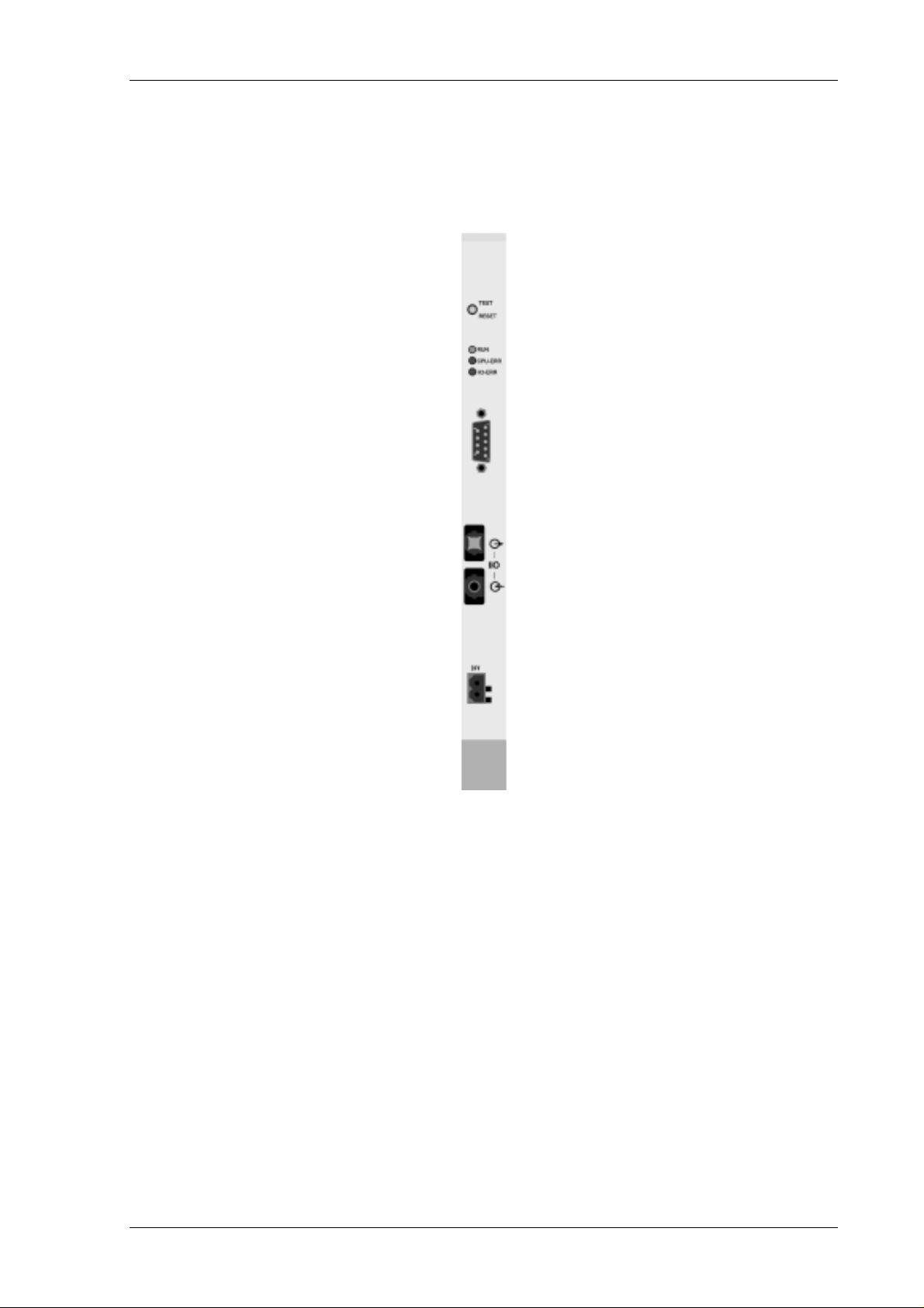
Status LEDs
3 Status LEDs are shown on the front panel of the C1120 interface:
1. RUN : If this LED shows the C1120 interface is ready to work.
2. CPU-ERR : Intermitting light indicates mismatch of number of modules in
the configuration and II/O-Lightbus ring. Possibly the
EEPROM memory is defect.
Uninterrupted light indicates a general interface error. A cold
start is recommended prior to change of the interface.
3. II/O-ERR : Intermitting light indicates a general II/O-Lightbus error, which
can be analyzed in details or serviced by the special functions.
Date 27.06.97 Version 2.1 Page 33 of 52
Page 34

C1120 S5 to II/O-Lightbus Interface Beckhoff II/O-Lightbus System
2.4 Slave Setup
The C1120 interface is able to interface to a PLC behaving as a slave to a Master PLC with
C1120 interface. In this configuration, the slave C1120 interface is driven by a (standard)
master system, which supervises the II/O-Lightbus. I/O-data transmission and other
interesting applications are available in this configuration. Configuring an interface as a slave
is done with the help of this menu:
The menu offers two tables, a status line and the usual function keys:
Function keys:
F1 HELP
displays help text.
F2 EDIT INPUTS
changes to the menu to edit the input data table.
F3 EDIT OUTPUTS
changes to the menu to edit the output data table.
F4 EDIT CONFIGURATION
changes to the menu to edit the slave configuration.
Page 34 of 52 Version 2.1 Date 27.06.97
Page 35

C1120 S5 to II/O Lightbus Interface Beckhoff II/O-Lightbus System
F6 PROJECT MANAGER
the slave project manager is under development.
F7 PRINT (SLAVE) PROJECT
the print function is under development.
F8 SAVE PROJECT
saves the configuration to the hard disc.
F9 ONLINE MENU
changes to the online menu.
F10 PREVIOUS MENU
changes to the main menu.
Date 27.06.97 Version 2.1 Page 35 of 52
Page 36

C1120 S5 to II/O-Lightbus Interface Beckhoff II/O-Lightbus System
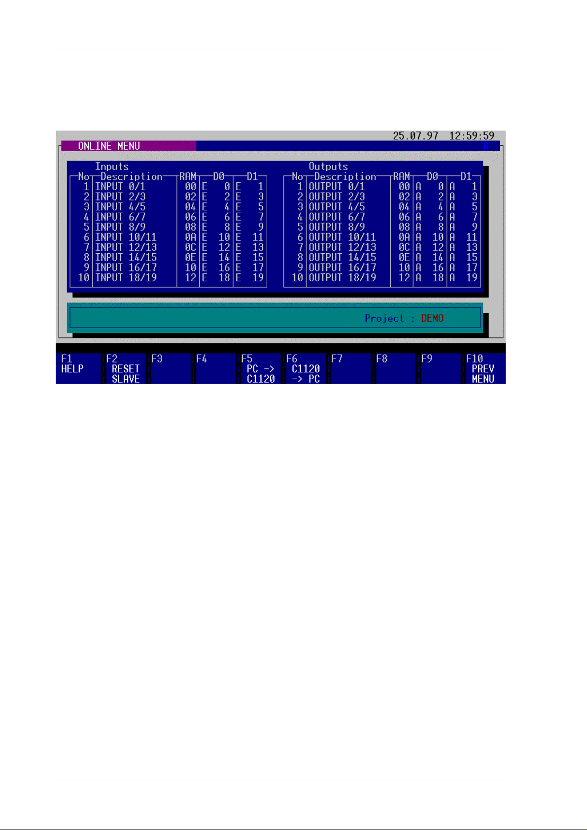
Edit Inputs
This menu helps editing the input data for the PLC. Output data are edited with a special
menu. The field "No" shows the line number of the table, "description" shows a text edited by
the user. The field "RAM" shows the offset address of the slave receive buffer. The fields
"D0", "D1" hold the PLC input addresses for the data in the RAM offset addresses of the
slave receive buffer.
Before inserting a new line with key "F4", no line can be edited.
Function keys:
F1 HELP
displays help text.
F4 INSERT LINE
inserts a new line at the actual cursor position. Following line numbers are
incremented.
F5 DELETE LINE
deletes a line at the actual cursor position. Following line numbers are
decremented.
F10 PREVIOUS MENU
changes to the main menu.
Page 36 of 52 Version 2.1 Date 27.06.97
Page 37

C1120 S5 to II/O Lightbus Interface Beckhoff II/O-Lightbus System
Edit Outputs
This menu helps editing the output data for the PLC. Output data are edited with a special
menu. The field "No" shows the line number of the table, "description" shows a text edited by
the user. The field "RAM" shows the offset address of the slave transmit buffer. The fields
"D0", "D1" hold the PLC output addresses for the data in the RAM offset addresses of the
slave transmit buffer.
Before inserting a new line with key "F4", no line can be edited.
Function keys:
F1 HELP
displays help text.
F4 INSERT LINE
inserts a new line at the actual cursor position. Following line numbers are
incremented.
F5 DELETE LINE
deletes a line at the actual cursor position. Following line numbers are
decremented.
F10 PREVIOUS MENU
changes to the main menu.
Date 27.06.97 Version 2.1 Page 37 of 52
Page 38

C1120 S5 to II/O-Lightbus Interface Beckhoff II/O-Lightbus System
Edit Configuration
This menu is used to edit the configuration data of the C1120 interface.
The pageswitch mechanism provides a consistent process image to the PLC at any time of
processing: While one process image is switched to the PLC, I/O communication is done with
a second process image. The fields "Pageswitch inputs" and "Pageswitch outputs" represent
the memory addresses of the I/O bytes which cause a pageswitch when they are accessed, the
lowest input and highest output byte by default. Different PLC CPU´s scan the process image
either from the lowest or from the highest addresses. The first memory access of the scan
should cause a pageswitch for the inputs, the last for the outputs. The default setting is
prepared to serve CPU´s, which scan the process image beginning with the lowest address.
The field "Status address" contains the address of the status byte. Following information is
reported to the PLC:
Statusbyte.0 : not used
Statusbyte.1 : not used
Statusbyte.2 : II/O-Lightbus Timeout error flag
Statusbyte.3 : not used
Statusbyte.4 : Inputs valid flag
Statusbyte.5 : not used
Statusbyte.6 : not used
Statusbyte.7 : not used
The indication of an II/O-Lightbus timeout can be configured with the help of the
configuration field "watchdog time". If during the choosen time interval no valid Lightbus
telegram is being received, an error status event is reported equivalent to the setup fiel d "S5
error request". By setting the field "watchdog time" to value "0", the watchdog is disabled.
Page 38 of 52 Version 2.1 Date 27.06.97
Page 39

C1120 S5 to II/O Lightbus Interface Beckhoff II/O-Lightbus System
Setting the field "S5 error request" to value "0" (default) results in switching the PLC to
STOP mode with an acknowlege delay by deleting the addresses of the I/O bytes in the dual
port memory of the C1120 interface. The acknowlege delay event can be managed by the PLC
by programming the OB 23 and 28.
Setting the field "S5 error request" to value "1" results in leaving the I/O addresses undeleted.
A static display of the last I/O status remains in the process image unchanged. The status byte
reports an error by setting the error flag, anyway.
Function keys:
F1 HELP
displays help text.
F2 SET DEFAULT
sets the configuration to default values.
F10 PREVIOUS MENU
changes to the main menu.
IMPORTANT REMARK regarding the page number:
The page number for data exchange with the PLC is configurable, beginning with
interface version numbers above V 1.51. Up to Version 1.51, the page number for
data exchange is 0 by default.
Date 27.06.97 Version 2.1 Page 39 of 52
Page 40
C1120 S5 to II/O-Lightbus Interface Beckhoff II/O-Lightbus System
Online Menu
This menu is used to communicate between the configuration PC and the C1120 interface:
Upload and download of setups is managed.
Function keys:
F1 HELP
displays help text.
F2 RESET SLAVE
Resets the C1120 interface, processing following steps:
- self test of the C1120 interface,
- activation of the configuration stored in the EEPROM memory.
The status of the C1120 interface is displayed in the status line after the reset. This
function only takes place, if the PLC is residing in STOP mode.
F5 PC -> C1120
Transmits the configuration data to the C1120 interface. The interface is able to
process propperly under following circumstances: A correct configuration is
transmitted, afterwards a reset or cold start is forced. During this procedure, the
PLC has to reside in STOP mode.
Page 40 of 52 Version 2.1 Date 27.06.97
Page 41

C1120 S5 to II/O Lightbus Interface Beckhoff II/O-Lightbus System
F6 C1120 -> PC
Reads the actual configuration from the C1120 interface to the PC.
F10 PREVIOUS MENU
changes to the main menu.
Date 27.06.97 Version 2.1 Page 41 of 52
Page 42

C1120 S5 to II/O-Lightbus Interface Beckhoff II/O-Lightbus System
2.5 Project Manager
With the help of this menu, different setups can be managed under the name of projects:
Function keys:
F1 HELP
displays help text.
F2 SET PATH
changes to new drive path for project file.
F3 CHANGE DIRECTORY
changes to new directory in a path for project file.
F4 MAKE DIRECTORY
generates a new directory in a path for project file.
F5 DELETE DIRECTORY
deletes an empty directory.
Page 42 of 52 Version 2.1 Date 27.06.97
Page 43

C1120 S5 to II/O Lightbus Interface Beckhoff II/O-Lightbus System
F6 OPEN PROJECT
Loads a project from the actual directory.
F7 MAKE PROJECT
generates a new project in the actual directory.
F8 DELETE PROJECT
deletes a project from the actual directory.
F9 COPY PROJECT
Copies a project from the actual directory to any path and/or directory.
F10 PREVIOUS MENU
returns to master setup menu.
Date 27.06.97 Version 2.1 Page 43 of 52
Page 44
C1120 S5 to II/O-Lightbus Interface Beckhoff II/O-Lightbus System
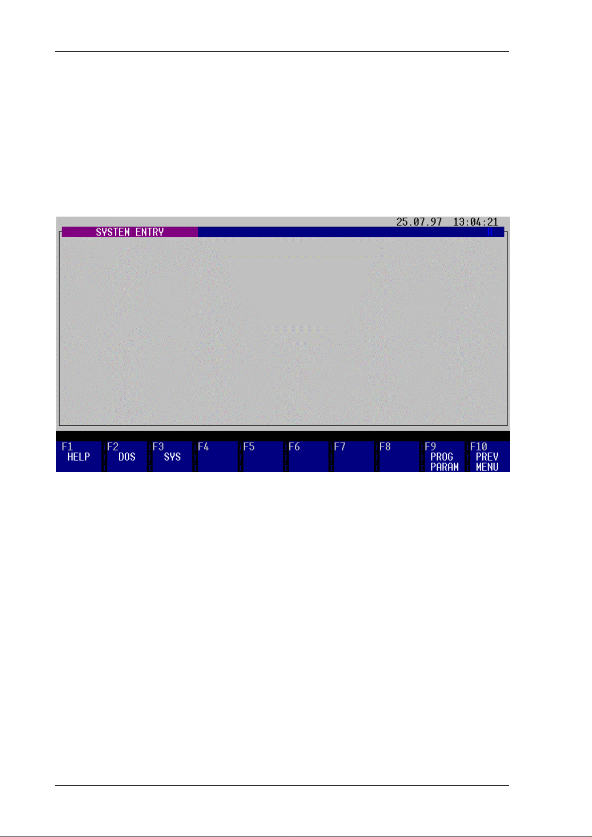
2.6 System Configuration
System Entry
Pressing F10 from the main menu leads to the system entry menu, from here the user can
choose the menus DOS, SYSTEM and PROGRAM PARAMETER.
Function keys:
F1 HELP
displays help text.
F2 DOS
Opens a DOS shell.
F3 SYSTEM
offers the submenus language and logfile.
F9 PROGRAM PARAMETER
contains the configuration parameters of the configuration software.
F10 PREVIOUS MENU
returns to master setup menu.
Page 44 of 52 Version 2.1 Date 27.06.97
Page 45

C1120 S5 to II/O Lightbus Interface Beckhoff II/O-Lightbus System
System
This menu offers the submenus LANGUAGE and LOGFILE.
Function keys:
F1 HELP
displays help text.
F3 LANGUAGE
offers the submenu LANGUAGE to choose different language options.
F4 LOG FILE
offers the submenu LOG FILE containing status history information.
F10 PREVIOUS MENU
returns to master setup menu.
Date 27.06.97 Version 2.1 Page 45 of 52
Page 46

C1120 S5 to II/O-Lightbus Interface Beckhoff II/O-Lightbus System
Language
This menu is used to change the actual menu language during program execution:
Function keys:
F1 HELP
displays help text.
F2 GERMAN
switches to german language menu.
F3 ENGLISH
switches to english language menu.
F10 PREVIOUS MENU
returns to master setup menu.
Page 46 of 52 Version 2.1 Date 27.06.97
Page 47

C1120 S5 to II/O Lightbus Interface Beckhoff II/O-Lightbus System
Log File
With the help of this menu the logfile can be displayed to review the event history:
Function keys:
F1 HELP
displays help text.
F5 COPY LOGFILE
Copies the file ’PROGRAM.LOG’ to the drive set in the menu "Programm
Parameter" (floppy, etc.).
F10 PREVIOUS MENU
returns to master setup menu.
Date 27.06.97 Version 2.1 Page 47 of 52
Page 48

C1120 S5 to II/O-Lightbus Interface Beckhoff II/O-Lightbus System
Program Parameter
The configuration for the configuration program for the C1120 interface is set and stored with
the help of this menu:
It is possible to move the cursor through the mask to access and change parameters of the
program.
The field "Language" is used to set the default language to german ("0") or english ("1").
The parallel and serial port is configured by changing the port number in the equivalent fields.
A "1" in the field "LCD-Display" sets a display color set for LCD requirements.
The fields "Harddisc" and "Floppy" show the actual active drives.
Function keys:
F1 HELP
displays help text.
F9 SAVE PAGE
saves the setting to the configuration file.
F10 PREVIOUS MENU
returns to master setup menu.
Page 48 of 52 Version 2.1 Date 27.06.97
Page 49

C1120 S5 to II/O Lightbus Interface Beckhoff II/O-Lightbus System
3 C1120 Interface: Technical Data
CPU
memory
Ports
Field bus
Transmission rate
Power supply
Current consumption
Housing
80C166 Communication processor
COM1 serial port
eqiv. RS232 C or 20 mA current loop
occupied by the configuration pr ogram
Beckhoff II/O-L i ghtbus System
2,5 MBaud, 32 Bit user data in 25 µs
5V from S5-PLC Bus
1,5 A from S5-PLC Bus
S5 Adaption capsule for intelligent peripherials
Date 27.06.97 Version 2.1 Page 49 of 52
Page 50

C1120 S5 to II/O-Lightbus Interface Beckhoff II/O-Lightbus System
4 Installation Remarks
4.1 Assembly to the S5-PLC rack
1. Switch off PLC and external power supplies
2. The C1120 interface should be mounted in a slot for intelligent peripherials or
communication processors (slot 0) of the S5- rack CR700-1.
3. Pull off the blind plug and place the C1120 interface in the slot like any other
interface.
No external power supply is necessary for the C1120 interface, it is driven directly from the
S5 PLC Bus. The powero n of the interface follows the power on of the PLC. At this time, all
fiber optic connections of the Beckhoff Lightbus ring have to be connected to maintain a
proper initialization.
4.2 Connecting to a PC
System requirements
For configuration and address initialization of the C1120 interface following equipment is
required:
- An IBM PC/AT or compatible PC with at least 640 kByte memory,
- a serial port,
- optional a parallel port,
- a monochrom- or color monitor and a hercules, EGA- or VGA- compatible
graphic adapter,
- a 5¼" or a 3½" floppy disc,
- DOS 3.3 or higher or a compatible operating system,
- a standard serial RS232- cable with 9-pin connector (pinout see annex).
Page 50 of 52 Version 2.1 Date 27.06.97
Page 51

C1120 S5 to II/O Lightbus Interface Beckhoff II/O-Lightbus System
Interface ports for connection with a PC
The interfacing is realized with a standard serial RS232- cable with 9-pin connector (pinout
see annex) for the port connector of the C1120 interface.
Date 27.06.97 Version 2.1 Page 51 of 52
Page 52

C1120 S5 to II/O-Lightbus Interface Beckhoff II/O-Lightbus System
5 C1120 Serial Port Pinout
Pinout of RS232 C / current loop port
(9-pin SUB-D connector on front of C1120)
Pin Signal Port
1
2
3
4
5
6
7
8
9
TXD RS232 C COM2:
TXD RS232 C COM1:
RXD RS232 C COM1:
RXD RS232 C COM2:
Signal
GND
TXD 20mA+ COM1:
TXD 20mA- COM1:
RXD 20mA+ COM1:
RXD 20mA- COM1:
-
Page 52 of 52 Version 2.1 Date 27.06.97
 Loading...